
Chapter 6: OTS Sample Documentation
One of the challenging issues relating to OTS projects is their documentation. In many projects, I have seen that documentation becomes less of a priority as the pressure grows on engineering tasks. Drawing up the documentation after engineering tasks had been carried out was not unusual when I first started working on OTS projects in the late 1980s. In certain projects, documentation was only drawn up once the OTS project had been delivered.
Documenting the OTS project will help in delivering a good project, meeting expectations, and identifying issues early enough so that they can be resolved before it becomes a question of fire-fighting. Does this ring a bell?
In the next section of this chapter, we will go over what documents are required for the V-model and see how this can help in project delivery.
In later sections of this chapter, we will provide a template for every document on the OTS project that OTS suppliers and users can use to help them start with their documents.
Creating these documents certainly takes time, so it needs to be well planned within the OST project to derive maximum benefit from them.
Well-documented test procedures, for example, will set expectations and no surprises will come to light in these tests, while a good Statement of Requirements (SOR) document will help in achieving correct delivery to the end user.
In this chapter, we will cover the following main topics:
- SOR document template
- DDS document template
- FDS document template
- MAT document template
- FAT document template
- Maintenance manual document template
- Model manual document template
- Project execution plan document template
- Training and competency philosophy document template
- Training plan document template
- Data collection document template list
V-model document structure
As mentioned in previous chapters, we have adopted the V-model as a solution in building and delivering the OTS project.
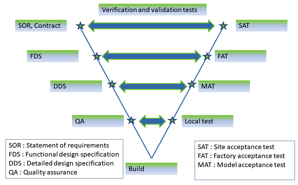
Figure 6.1 – Verification and validation process of OTS projects
To follow this model, we will need to generate multiple documents to be able to deliver using this model. In this chapter, we will discuss these documents and provide a template and a generic table of contents for these documents that can be used as a reference in any OTS project that wishes to follow this model.
SOR document template
The SOR document is a very important document that will define what the end user wants. This will help the supplier to fully understand what the scope is.
The following is an example that can be used as a template for OTS/Multi-Purpose Dynamic S/Digital Twin (OTS/MDPS/DT) projects.
Introduction
A brief introduction to the OTS project as well as the Integrated Control and Safety System (ICSS), if applicable, will be the start of this section. The aims and objectives should be listed in this section as well.
A clear outline of the supply and scope of the work should be included, while the responsibilities of different parties should be added to the end of the introduction section.
OTS overview
In this section, the areas of simulation should be listed in some detail. The expected performance requirements of the model should also be noted here.
Model overview
The scope of the model will need to be detailed here, along with a list of uses for the model in training and engineering studies.
A list of all the different areas to be modeled will also need to be included.
Trainee environment
The trainee environment should be described in detail, including aspects such as how many trainees you need to train at the same time.
Instructor environment
The instructor environment should be described in detail, including aspects such as how many instructor graphics pages you require in order to simulate Field-Operated Devices (FODs).
The number of custom malfunctions will also need to be noted. In the Functional Design Specification (FDS) document later, you will need to explain what is expected from every one of these malfunctions.
As for a generic malfunctions list, the minimum required will need to be listed here. The minimum requirements for generic malfunctions could include the following:
- Valves: To be able to malfunction valves to fail valves to closed, fail open, in last good position and to a certain specified valve position.
- Pumps: What causes motor-driven pumps to be tripped or inhibits them from starting, along with performance degradation. The same can apply to other motor-driven devices such as fans.
- Transmitters: Transmitters could be failed to high and low values or fail in a certain position. The application of noise and drift to the transmitter could also constitute a generic malfunction.
- Heat exchangers: Fouling on both sides of the process (hot and cold) should be a generic malfunction.
- Global instrument air failure: As the name suggests, this malfunction will prohibit instrument air from reaching all air-operated instruments.
Generic malfunctions are defined by the software used to build the process model, but the minimum requirement should at least be covered by the process modeling software.
Engineering environment
Similarly, the engineering environment will need to be described here, along with the activities that the engineer will need to be able to carry out on the OTS. These need to include ICSS and process areas.
Process models
The accuracy of the model will need to be noted here, along with the data that will be supplied to build the model.
Areas to be modeled with lower fidelity will need to be listed along with the extent to which modeling will need to be implemented in relation to these areas. The model's boundaries should also be listed here.
Another area to be addressed in this regard is third-party software that will need to be modeled in the process model. A description should be provided here.
System requirements
In this section, the hardware of the OTS is specified, along with a description of the minimum requirements that suppliers will have to satisfy.
Examples include the capacity of all hardware CPUs and their maximum load when the OTS is working at its hardest. Usually, a 20% CPU-free capacity is mentioned here. At any point, CPU loading should not exceed 80%.
A description should also be provided of the digital security requirements expected to be met by the OTS supplier.
Another item to be included here is the software licenses and what the end user expects the licenses to cover. Some suppliers favor runtime over development licenses, which may be confusing for end users. End users will need to specify here what they need to do with the OTS and for how long – will a license lasting a few years suffice, or is a perpetual license required?
If a remote connection to the OTS is required, this will also need to be stated here.
Other requirements, such as printers and their consumables, as well as two-way radios, can be set out here.
Training requirements
In this section, the training required to be delivered by the OTS supplier to the end user should be mentioned, so as to give the supplier a good idea of what the OTS will be used for. This will help the supplier to offer a system fit for purpose. Typically, you will require the following as a minimum:
- Instructor training
- OTS training scope
- Maintainer training
- Maintenance training to keep the system running smoothly, provide system backups, and assist system administration in terms of day-to-day use
- Engineering training to be able to use the system for engineering by providing knowledge of changing the process model and updating the ICSS
One of the main aims of getting the OTS is to train personnel, so this section of the SOR has to be well defined and explained to the OTS supplier in order to help them deliver the correct system.
Documentation
Typical documentation (as a minimum) is listed here:
- Bill of materials
- FDSs
- Modeling standards
- A detailed design document (optional) as per project requirements
- Model acceptance testing procedure
- Factory acceptance testing procedure
- Site acceptance testing procedure
- Instructor manual
- Engineering manual
- Maintenance manual
- Quality plan
- Health, Safety, Security, and Environment (HSSE) plan
- Hardware and all wiring plans
- A day-to-day action list
Later on in this chapter, we will provide templates for many of the documents listed in this section.
Acceptance testing
Typical testing (as a minimum) is as follows:
- Model acceptance test (MAT)
- Factory acceptance test (FAT)
- Site acceptance test (SAT)
Other tests may be required and these will be bespoke for the project. The preceding are the minimum requirements only. In every test, end user expectations should be detailed.
Project management and project delivery schedule
In this section, project delivery expectations and all milestones in terms of timing should be explained. This will help the OTS supplier in planning their OTS delivery to meet the project milestones set by the contractor. The main milestone will be the delivery one, but a time limit should also be included regarding when other milestones should be achieved, such as the MAT, FAT and SAT.
This could be in the form of one paragraph to say the OTS supplier should work toward getting the MAT completed by a certain date, and similarly for the FAT, SAT, and final delivery.
Maintenance aspects
Maintenance aspects to be carried out by the user to keep the OTS in a good and healthy status, this requirement should be noted here so that the supplier will make sure that it is part of the OTS delivery and the maintenance aspects are as easy as possible for the end user. The OTS user can then include in their plan what training they need to provide to the user to help them achieve and meet the expectations set in the SOR.
Quality assurance
Quality assurance requirements will be set out in this section.
Appendices
The appendices will be at the end of the SOR.
DDS document template
Introduction
A brief introduction to the project.
Objectives
The objective for having the OTS system and its usage will be described in this section, along with a vision of how to get the most out of the OTS build phase.
Overview
An overview of the OTS build will be described here to include the following:
- Scope of the modeled process
- Execution summary
- General specifications
- Dynamic model accuracy
- Model performance
- Initial model conditions
- Model data
After providing the overview, a detailed modeling standard will be explained in the next section.
Process model and modeling standards
Typical sections are as follows:
- Component slates.
- Thermodynamic methods.
- Model partitions (if the model is divided into more than one Process Area Model (PAM).
- Modeling standards.
- Non-standard process modeling.
- Standard malfunctions.
- Custom malfunctions.
- Model control layer.
- This is the control layer used during the MAT and to be disabled/removed when the model is integrated into the ICSS.
- Other process models (such as the subsea model for FPSOs).
It is quite important to set the modeling standard and get it agreed before starting the model building process. The OTS project will have many OTS engineers working on model building and to make sure that all models are built to the same standard, this document should provide the basis for this.
Non-ICSS controls
All non-ICSS controls and how they will be dealt with in the OTS environment should be listed here. Typical examples include the following:
- Power management systems
- Compressor control systems
- Fire and gas systems
- Turbine vibration systems
- Mechanical interlocks
In this section, the expectations of these non-ICSS controls need to be clearly explained and agreed upon between the OTS supplier and the end user. Failing to do that will bring unwanted surprises during the OTS test that no one wants. Take the first example of power management systems. The OTS supplier will try to simplify this as much as they can, but let's say the end user wants to see in detail what happens when one gas turbine is lost and the power is shed and which equipment will keep running based on the available power left following the gas turbine trip.
Another example is the vibration monitoring systems in a compressor. Again, the OTS supplier can simplify this by having fixed, healthy (non-trip) numbers for these all the time if this is considered out of scope, or it can have them modeled simply as a function of the compressor speed and load. In this section, this functionality needs to be explained and agreed upon.
Instructor station
The sections to be included here as a minimum are as follows:
- Standard instructor functions
- Instructor graphics
- Trainee performance monitoring tools
- Training scenarios and exercises
There are many OTS suppliers, and every one will have their own instructor station basic functionality. In this section, the functionality of the instructor station needs to be explained and address the points that the OTS end user raised in their SOR document.
Appendices
Suggested appendices here are as follows:
- Appendix A – Marked-up Piping and Instrumentation Diagrams (P&IDs)
- Appendix B – Heat and mass balance
- Appendix C – List of FODs
- Appendix D – Instructor graphics
- Appendix E – Boundary list
Now we can look into the FDS template in the next section.
FDS document template
As has been mentioned previously in the book, many projects tend to merge the Detailed Design Specification (DDS) and FDS in one document and call it the FDS. This document will be used in the MAT and FAT to test against the relevant section in each test.
The following is example content of the merged FDS document. If the project is deciding to use a separate DDS, then you can omit the repeated sections and refer to the DDS. Mainly, the process model and modeling standards section, for example, will need to be referenced in the DDS.
Introduction
A brief introduction to the project.
Objectives
The objective for having the OTS system and its usage will be described in this section with a vision of how to get the most out of the OTS build phase.
Overview
An overview of the OTS build will be described here to include the following:
- The scope of the modeled process
- Execution summary
- General specification
- Dynamic model accuracy
- Model performance
- Model initial conditions
- Model data
When writing the overview for this document, we need to address all the points that the end user will need to see in future OTS tests, namely, the MAT and the FAT. To a certain degree, the SAT should be considered when writing the overview of this document. Next, we will look into the software and hardware design section of the FDS.
Software and hardware design
Typical sections include the following:
- Software architecture
- Process model software design (such as HYSYS®, UniSim®, ProsDS®, and DYNSIM®)
- Other process model designs (such as OLGA® and Ledaflow®)
- Third-party control emulation (such as CCC® and Mark VIe®)
- Software licenses
- Other licenses (if any)
- Hardware design
We tried to list the most common pieces of software here. Of course, many others are used in the industry. For example, FPSO comes with specialized software to keep the ship balanced all the time. In this section, software like this should be mentioned.
Process model and modeling standards
Typical sections include the following:
- Component slates.
- Thermodynamic methods.
- Model partitions (if the model is divided into more than one PAM).
- Modeling standards.
- Non-standard process modeling.
- Standard malfunctions.
- Custom malfunctions.
- Model control layer .
- This is the control layer used during the MAT and to be disabled/removed when the model is integrated into the ICSS.
- Other process models (such as the subsea model for FPSOs).
As was mentioned in the DDS section, it is vitally important to agree on these standards in this section so that all OTS engineers will follow the same and the end user will be unable to notice that different engineers built different sections of the process model.
Non-ICSS controls
All non-ICSS controls and how they will be dealt with in the OTS environment should be listed here. Typical examples include the following:
- Power management systems
- Compressor control systems
- Fire and gas systems
- Turbine vibration systems
- Mechanical interlocks
Fire and gas systems are usually out of the scope of the OTS, but experience has shown that including a small portion of this in the OTS is very beneficial for end users. The simple inclusion of how to override a fire and gas detector or release foam in an area would benefit operators a lot.
The Human-Machine Interface (HMI) graphics for fire and gas sections can be tested on the OTS as well of course.
Instructor station
The sections to be included here as a minimum are as follows:
- Standard instructor functions
- Instructor graphics
- Trainee performance monitoring tools
- Training scenarios and exercises
One of the main uses of the OTS is training, and this is achieved by utilizing the instructor station to its maximum capabilities. In this section, it is paramount to show these capabilities.
System integration
The sections to be included here as a minimum are as follows:
- Process model-to-process model integration (more than one PAM)
- Process models to other modeling packages (such as HYSYS® to OLGA®)
- Process model-to-ICSS integration
- Process models to third-party controls (such as CCC® and Mark VIe®)
When writing this section, the OTS supplier should keep in mind that end users might not be familiar with all the terms in this section. It needs to be written in such a way that engineers who are new to the OTS can easily understand it.
ICSS
This section will be specific to the ICSS (such as Emerson's DeltaV®, Honeywell's Experion PKS®, Yokogawa's CS300®, and Foxboro I/A®).
Full details of the ICSS used in the OTS need to be described here.
OTS communication
The protocol used to get the ICSS to talk to the process models and any other third party in the OTS (such as Object Linking and Embedding (OLE) for process control (OPC)) will need to be described in detail in this section.
The flow of data between different parts of the OTS will need to be made clear here, and any other IOs not using this protocol to communicate will need to be declared here.
General
Typical sections here include the following:
- System security
- User access
- Virus protection and Windows system upgrades
- Backup requirements
Another general section might be system remote connections for supplier access to maintain the system and for end users to access the system from different places.
Appendices
Suggested appendices here are as follows:
- Appendix A – Marked-up process and instrumentation diagrams
- Appendix B – Heat and mass balance
- Appendix C – List of FODs
- Appendix D – Instructor graphics
- Appendix E – Boundary list
MAT document template
Model acceptance testing is the first witness test by the end user. It is important to start the witness testing on a positive that can set the scene for other tests.
The OTS is considered ready for the MAT when all process models are integrated and the model has gone through model acceptance readiness testing by the OTS supplier.
It is recommended not to make the MAT the first taste of the system by the end user. In Chapter 3, OTS Project Execution and Best Practices, we mentioned that every process model is built from integrating smaller process area models (PAMs). When all of these smaller pieces are integrated and tested together, then the model is ready for the MAT. These days, with virtual meetings being the norm, it is best to show the end user when every PAM is completed. This will help in identifying issues early enough in the build process and not to leave them to surprise everyone on the MAT day.
In this document, the OTS supplier should explain the flow of the test and what should happen on every day of the test, right from the start and finish times to logging model issues, planning to fix issues, and signing the test certificate. What makes the MAT be regarded as successful? What is expected from the end user? These questions need to be answered in this document.
Introduction
A brief introduction to the MAT will be required, with typical subsections including the following:
- Purpose
- Scope
- Holds
- Abbreviations
This test aims to be able to declare the model ready for integration within the ICSS. This will be the main purpose of this test. The scope of this test needs to be clear and agreed between the OTS supplier and end user. In the next section of the MAT document, the test methodology should be detailed.
Test methodology
Typical subsections include the following:
- General
- Conducting the tests:
- End user responsibility
- Supplier responsibility
- Other third-party contractors' responsibility (if any)
- Participants
- Agenda:
- Overall MAT agenda
- Daily MAT agenda
- Daily meetings
- Post-test meeting
- Recording of tests
- Classification of incident logs
In this section, the test methodology is explained. In the next section, the test procedures should be listed and explained.
MAT procedures
These will be specific for each project, but here are some examples:
- Review of documentation
- Model completeness – Model topology
- Model completeness – Data check
- Model completeness – Model equipment performance check
- Model completeness – Model boundary check
- Model steady-state design conditions
- Model shutdown
- Model startup
- Standard malfunctions test
- Custom malfunctions test
- Instructor functionality test
- Model soak test – Steady-state case
- Model soak test – Cold case
- End user special tests
The MAT is divided into a few sections. The first will ensure that the correct model scope is included in the process model. That is achieved by making sure that the OTS supplied uses the correct documentation, process and instrumentation diagrams, heat and mass balance, and so on. The second section will include the process model operations, such as process shutdown and startup. Another section will be the instructor station functionality, including custom and standard malfunctions, for example. The final section will cover model stress testing, such as leaving the steady-state model to run for a number of hours. Each of these tests should have the following subsections:
- Scope
- Time required
- Test procedure
- Acceptance criteria
It is important to be clear and explain every test in its scope, the time required to carry on the test, the test procedure itself, and the acceptance criteria. This will help the OTS supplier and end users to perform a good test and will help in planning the test, as some tests could be run in parallel. For example, a model soak test can be run overnight, so all test parties can plan their time accordingly.
Appendices
Suggested appendices here are as follows:
- Appendix A – Incident log sheet
- Appendix B – MAT sign-off sheet
- Appendix C – List of key streams
- Appendix D – Shutdown procedures
- Appendix E – Startup procedures
In many cases, especially for greenfield projects, the operating procedures will not be available at the time of the MAT. It should be noted in this document what the bases are of these operating procedures. In the case of them not being available, what should be used during the test? Experience has shown that using an experienced operator to drive the process is very beneficial and helps all parties to achieve a successful MAT.
FAT document template
In this example, we are doing software testing in the FAT, and hardware testing in the SAT. However, hardware tests can be done in the FAT and the SAT will be left as a travel-well test. Sometimes, for large-scope OTSs in particular, time constraints will apply, and the hardware test will be moved to the SAT.
Introduction
A brief introduction to the FAT will be required, with typical subsections including the following:
- Purpose
- Scope
- Holds
- Abbreviations
The main purpose of this test is to declare the OTS ready to be shipped to the site. In the purpose section, this needs to be stated clearly and a brief criterion for success should be noted.
Test methodology
Typical subsections include the following:
- General
- Conducting the tests:
- End user responsibility
- Supplier responsibility
- Other third-party contractors' responsibility (if any)
- Participants
- Agenda:
- Overall FAT agenda
- Daily FAT agenda
- Daily meetings
- Post-test meeting
- Recording of tests
- Classification of incident logs
A brief introduction to the test methodology is set in the general section. The Conduct of the tests section sets out the responsibilities of end users and the OTS suppliers. All required participants and their contacts should be listed in the Participants section.
The agenda of the FAT will be clearly noted in the Agenda section. Every day's agenda should be stated along with how the test will be recorded and how the test incidents will be classified.
The next section of the document will set out the FAT procedures.
FAT procedures
These will be specific for each project, but here are some examples:
- Review of the documentation
- Design basis inspection
- MAT incident log sheet review
- Integrated steady-state case test
- OTS system soak test – Steady state
- Integrated model shutdown
- Integrated model startup
- Emergency shutdown test
- Instructor functionality test
- Standard malfunctions test
- Custom malfunctions test
- Non-standard modeling item tests
- End user special tests
- ICSS communication tests
As we can see, there are a few sections in this test. In the first section of the FAT, we are making sure of the scope of the OTS as per the agreed scope in the FDS. The next section will involve making sure that all the logged incidents are closed and addressed properly in the FAT. The next section of the test involves making sure that the steady-state process model is as per the agreed accuracy. Then, in the next section of the test, we will move into the operations area. Normal process shutdown, normal startup, and emergency shutdown operations will be carried out to test the simulation. The instructor functionality will be the next section to be tested in the FAT.
Some ad hoc tests by the end user should be allowed to give them the flexibility to test special areas of concern in the process plant.
Each of these tests should include the following subsections:
- Scope
- Time required
- Test procedure
- Acceptance criteria
Similar to the MAT, it is important to be clear and explain every test in terms of its scope, the time required to carry out the test, the test procedure itself, and the acceptance criteria. This will help the OTS supplier and end users carry on a good test and will help in planning the test, as some tests could be run in parallel.
Appendices
Suggested appendices here are as follows:
- Appendix A – Incident log sheet
- Appendix B – FAT sign-off sheet
- Appendix C – List of key streams
- Appendix D – Shutdown procedures
- Appendix E – Startup procedures
- Appendix F – Emergency shutdown procedures
- Appendix G – Special tests
- Appendix H – Training scenarios
In the next section, we will see a template for a SAT.
SAT document template
SAT in this example, is a travel-well test only. The software would have been tested in the FAT. Hardware visual testing is done in the SAT.
Introduction
A brief introduction to the SAT will be required, with typical subsections including the following:
- Purpose
- Scope
- Holds
- Abbreviations
The purpose of this section is to list what needs to be achieved by the end of this test. We did say that in this example, we will use this test as a travel-well test. The document scope should list what needs to be tested/checked in this test.
General
Typical subsections here include the following:
- SAT location
- Responsibilities
- Nominated persons
- Agenda
The test location is usually the final location for the system at the end users' premises. Every participant in the test needs to be assigned a responsibility that is clearly stated in this section. All participant contact information should be noted here.
Document practices
Typical subsections here include the following:
- Pass/fail indication
- Incidents
In this section, the recording of the test results will be explained, along with how the incidents will be logged and a plan to address them going forward.
Prerequisites
Typical subsections here include the following:
- FATs
- Documentation
- Test equipment
- Pre-SAT activities
- Health and safety
All the prior test records before getting to the SAT should be discussed in this section, as well as the status of the issues and how they were addressed. How to test the outstanding issues from the FAT (or MAT) will be detailed in this section.
SAT equipment tests
In this section, the OTS hardware test will be described. At least the following points should be addressed in this section:
- Documentation checks:
- Prerequisites documentation
- Hardware drawing checks
- BOM check:
- Visual inspection:
- Purpose
- Reference document
- Procedure
- Earthing test:
- Purpose
- Reference document
- Procedure
- AC power-up and power distribution tests:
- Purpose
- Reference document
- Procedure
- Other power up and distribution tests (UPS):
- Purpose
- Reference document
- Procedure
Since this test requires specialist expertise, for example, electrical engineers, this needs to be planned around the availability of resources, and this activity could be done in conjunction with other activities, especially the visual inspection of equipment.
Site acceptance testing functionality test
Typical subsections here include the following:
- Site integration test:
- Purpose
- Procedure
The purpose of this test is to verify and ensure integration between various components of the OTS system. In the Procedure section, the different tests will be listed and how they will be carried out.
List of incident log sheets
All incident log sheets should be covered here along with how to address the outstanding ones after the SAT.
Test log appendices
Suggested appendices here are as follows:
- Appendix A – Cabinet test log (if the OTS has cabinets to host the OTS servers)
- Appendix B – Site integration test
- Appendix C – SAT certificate
Instructor manual document template
This is to be used by the training instructor on a day-to-day basis and as a reference manual for OTS usage.
This document should include the full scope of the system and the planned training program, which includes a training plan and schedules.
This document (either a hard copy in the simulator room or an electronic copy on the OTS system) can be presented at any time to any auditors (such as the HSSE) to illustrate the overall professional approach to the build, delivery, and training plan for the OTS.
Introduction
A brief introduction to this manual will be required, with typical subsections including the following:
- Purpose
- Scope
- Holds
- Abbreviations
The instructor manual should be written in a way to help the OTS instructor in their day-to-day use of the simulators, which is the main purpose of this document.
ICSS process control system overview
In this section, the ICSS control system is described in detail – its architecture, the operator and engineering stations, and the ICSS servers and their hardware. In addition, the ICSS integrated into the OTS system is clearly defined and its capabilities are shown. The difference between the ICSS in the real plant and in the OTS environment should be clearly noted.
- ICSS architecture
- ICSS training station hardware
- ICSS training system environment
- ICSS server hardware
Different ICSS systems will work in different ways in an OTS environment. As regards Honeywell's ICSS, for example, in the OTS, the Process Automation System (PAS) and Safety Instrumented System (SIS) configurations are translated by engineering tools to be used in the OTS environment, while the Foxboro I/A® and Triconex® files are configured to suit the OTS environment. Emerson's DeltaV® will have its own engineering tools to make the ICSS suitable for use in an OTS environment.
OTS power up and power down
This is a very detailed, step-by-step procedure for the instructor to follow relating to power up, switching on all OTS equipment, launching all OTS software and the OTS ready to be used, powering down the full OTS system, stopping all OTS applications, and switching off all OTS equipment.
This procedure needs to be detailed, with screenshots at every possible step. This will save a lot of time and money for end users and suppliers.
In the past, I noticed that passwords are a challenge to remember on these systems, and there are many passwords with the full OTS system. I found documenting them in the instructor manual a good way to keep them. But if this is not advisable for certain projects, then these will need to be agreed upon in a process so as to have these available to the instructor.
Instructor interface overview
Full details of the instructor interface need to be documented here. Many OTS suppliers will have standard documentation for their instructor station software. There is no need to reinvent the wheel here and rewrite this in this section. A reference to the main software supply should be referred to just in this section. Only bespoke functionality, if any, should be declared and explained in detail here. A good example here would be custom malfunctions for every project.
Instructor training features
Training monitoring features will need to be documented in detail here. There are two types of instructor training features. The first is general features that come as a standard supply with the supplier software and the second are custom features designed and delivered specifically for the OTS being delivered. Only bespoke features will need to be listed and explained here and there is no need for the standard functionality explained in the main software documentation.
Maintenance manual document template
This is to be used by the person(s) responsible for maintaining the OTS and making changes to the software/hardware when needed.
Introduction
A brief introduction to this manual will be required, with typical subsections including the following:
- Purpose
- Scope
- Holds
- Abbreviations
The main purpose of this manual is for the OTS end user to use it in the day-to-day maintenance of the OTS, and explaining how to keep the system healthy from a hardware and software point of view. It also covers how to back up the OTS software to help in any file recovery, or even disaster recovery, and what to back up.
System architecture
Typical subsections include the following:
- Software architecture overview
- ICSS configuration
- Simulation components
- System integration
It is important to explain the system architecture and how it all fits together, including the simulation components and communication between them, to help system engineers understand the system better.
System description
Typical subsections include the following:
- Process model-to-process model integration (if applicable)
- Process model-to-ICSS integration
- Process model-to-other process model package integration (if applicable)
- Process models to third-party control systems (for example, CCC® and Mark VIe®)
In this section, all communication between the different software pieces is explained. This will help system and process engineers to fix issues should they happen during OTS use.
Base software
Typical subsections include the following:
- Process modeling software
- ICSS components
- Instructor station components
- Licensing
It is important to list all the base software used in the OTS and its licensing. Will a license expire soon? You don't want this to happen when you are in the middle of using the simulator.
System maintenance and diagnostics
Typical subsections include the following:
- Communication diagnostics
- User management:
- ICSS user management
- Process model user management
- Third-party control user management
- ICSS database downloading
This is a very important section that will describe and show how to diagnose the OTS system by showing examples of issues and their diagnostics. The last part of this section should deal with how to download a new ICSS database should the end user intend to do this themselves.
System features and notes
Typical subsections include the following:
- Initial condition loading
- ICSS historian features
- Other ICSS features
The ICSS is not designed to deal with initial conditions by default. In this section, it should be clearly noted how the ICSS will deal with saving and restoring the initial conditions.
System backup
In this section, a software backup recommendation will need to be noted for the following:
- ICSS backup
- Modeling software backup
- Other software
In the recommendation, there should be a list of what should be backed up on a daily, weekly, and monthly basis.
System restore
Every system should come with disaster recovery software and in this section, there should be a procedure on how to carry this out and how to maintain the software images to be current at all times.
System update
In the section, simple OTS updates need to be documented, so if the end user wishes to carry them out, they can.
Simple change examples include the following:
- Updated ICSS graphics
- Adding a transmitter to the process model and integrating it into the ICSS
- Changing the control strategy without adding IOs
A system update is a very detailed process, and it needs ICSS and OTS expertise to do this. Usually, the OTS end users get the OTS suppliers to do this, but others will choose to do this themselves and this section will help them in doing so.
Model manual document template
This is to be used by the person(s) responsible for maintaining the OTS process models and making changes to the software when needed.
Introduction
A brief introduction to this manual will be required, with typical subsections including the following:
- Purpose
- Scope
- Holds
- Abbreviations
This document is to be used by process engineers as a reference manual to upkeep the process model in the OTS.
OTS overview
Typical subsections include the following:
- Process model scope
- System software:
- Software architecture
- Process model design
- Other process model design (if any)
In this section, the process model scope is defined to know what is modeled and what is not in the scope. The software structure is highlighted as well as the versions of the process modeling software to be used.
Process model
Typical subsections include the following:
- Overview.
- A general description of the model, highlighting the following:
- Process model time steps
- Process model preferences
- Process model default settings
- Any special thermodynamic assumptions and calculations
- Process model topology.
- Every process area to be described under this section with any special modeling assumptions mentioned here.
- Process model-to-process model links need to be described in full here and show the testing results that made the connection work.
- Similarly, if there are other process model packages, then the links between the two packages will need to be detailed, and the test result should show how the link worked.
- Non-standard modeling.
- Special model calculations (such as spreadsheets in HYSYS® and UniSim®).
Other process model packages
If another process model is used (such as OLGA® or LEADFLOW®), this will need to be detailed here. Subsections will be almost the same as the main process model.
Appendices
Suggested appendices here are as follows:
- Appendix A – Heat exchanger calculations
A sample datasheet to be included, showing all the parameters used in the model and an example calculation if needed
- Appendix B – Control valve calculations
A sample datasheet to be included, showing all the parameters used in the model and an example calculation if needed
- Appendix C – Other valve calculations
A sample datasheet to be included, showing all the parameters used in the model and an example calculation if needed
- Appendix D – Model data summary
- Appendix E – Process model-to-process model links
- Appendix F – Any special thermo calculations
- Appendix G – Level datum used in the process model
So far, we have been looking at engineering documents. In the next section, we will deal with the training aspect of the OTS documentation.
Project execution plan document template
This is to be used by the project managers who are responsible for executing the project. It is the basis for the plans to be used in the execution. An OTS project is no different from other projects in requiring defined plans; there are often many people involved who have to integrate their activities and relatively complex technical details that need to be understood to set the execution of the project. It ranges from the mundane (for example, purchasing and later shipping) to specifics (for example, model testing and how this will be structured – the location, systems installed, team members present).
Introduction
A brief introduction to the project and the deliverables will be required, with typical subsections including the following:
- The purpose and objectives of the project
- Details of some of the system architecture anticipated
- Delivery requirements (space availability, scheduled dates)
- Abbreviations, glossary, and agreed project terminology
This document is to be used by process team members as a resource for executing the project.
Scope definition
Where possible, and to aid the understanding of the project, team members' details should be provided that cover the following:
- Hardware
- Software
- Model scope
- Control system scope
- Training scope
Execution plans
The details regarding execution will consist of a series of plans for different aspects of the execution. These should be as succinct and clear as possible. The supplier will frequently have delivered similar projects, so the majority of these plans are likely based on their previous experience. The end user/customer should look at these to determine whether they meet their expectations and, if not, request modifications to the appropriate parts. Typically, these plans cover the following:
- Schedule management
- Progress reporting, action logs, and the technical query system
- Documentation and deliverables management
- Scope change management
- HSSE management
- Quality management
- Risk and issues management
- Cost management
- Procurement management
- Hardware plan
- Resource management
- Communications management
Execution
These plans will be used within the execution of the project. The overall execution strategy can be set out with guidance on the different phases of the project and how these will be conducted. Typically, the following will be covered:
- Execution approach
- Execution steps
- Milestone definition
- Execution flowchart and stage gates
- Implementation plan
- Initiation phase
- Kick-off and data collection
- Design phase
- Model development phase
- Testing activities
- Site deployment
- Training
- Project close-out
These sections will support the development of the documentation that forms part of the project deliverables.
Training and competency philosophy document template
This document will set out the strategy for training delivery and will define the criteria for success.
Examples of sections to be included in this document are as follows.
Introduction
A brief introduction to the training and competency philosophy to be followed in the project will be required, with typical subsections including the following:
- System overview.
- A simple introduction to the DT system, concentrating on the capabilities of the system. The scope of the DT system needs to be mentioned here and, more importantly, the out-of-scope areas so that training limitations can be highlighted.
- Training overview.
- A general view of the training program and highlighting the competency that needs to be achieved when training is completed.
Objective
The purpose of the philosophy document will be explained in this section.
Scope
The DT training and competence philosophy document sets out the expectations and framework under which the training of CROs/CRTs, technicians, supervisors, and engineers will be conducted using the DT project prior to initial startup.
The competence and training process project needs to be explained in detail in this section.
OTS training model
The training model used will need to be set out in this section. An example can be found in Chapter 5, OTS Training and Delivery, of this book.
OTS standards
The criterion for training success should be explained here. The OTS standards set the benchmark for the competence of OTS trainees and require that evidence of competence be assessed for elements specific to the plant or job role. These will be based on the existing organization competence documentation. In Chapter 5, OTS Training and Delivery, this is explained in detail, but typical subsections include the following:
- Units: In this instance, the definition of a unit is an area of competence or training. Units can be standalone or supporting units, but typically, for plant-specific units, they will consist of elements and sections.
- Elements: These are a part or a subset of a unit. For every element, a competency standard will need to be demonstrated for every trainee.
- Sections: A section is an area of skill and/or knowledge to be demonstrated for each element.
Every organization will have its own training philosophy and, in this section, it will need to be demonstrated how the OTS standard will fit in with the main training philosophy of the organization.
Definitions and details of OTS standards
Typical subsections include the following:
- Normal operations
- Controlled startup and shutdown
- Preparation for maintenance
- Reinstatement following maintenance
- Control emergencies and critical situations
In every one of the subsections, a clear OTS standard should be defined and the way of achieving that competently through OTS training should be defined.
Training and assessment matrix
This is a full training matrix showing units, elements, and sections and what can be achieved in every training session.
An example of a unit would be the ICSS (HMI) functionality control system overview. An example of an element in the unit is the workstation functionality. The matrix will show whether that element will be trained on in every section. A section will be the preceding five bulleted points in the previous section, that is, from Normal operations to Control emergencies and critical situations.
Training model next steps
In this section, the status of the training will be highlighted on the training model discussed in the OTS training model section.
Training plan document template
This document will set out the project training plan. It should be a very detailed plan that will go into the content of every training session.
Examples of sections to be included in this document are as follows.
Introduction
In this section, it should be detailed how the OTS training plan should set out the project plan to utilize the OTS and define the training requirements. Example subsections include the following:
- Objective
- DT
- Benefits of the DT
The objective of this document is to align with the organization's training philosophy and provide the approach to every training session planned on the OTS.
Competency and assessment
The key principles for competency are knowledge, understanding, experience, and personal characteristics. Following the OTS experience, it is important that the trainees feel they are well trained and prepared, comfortable in their own ability to meet the requirements of their role. The OTS training plan details how the OTS will be used to train and demonstrate competence for predetermined elements specific to the operation of the simulated plant. Example subsections include the following:
- Competence and standards
- Assessment
- Trainee competence and assessment matrix
All the individual trainee requirements are divided into elements that could be assessed by the training instructor and recorded as such for every trainee. These records could be used to track the competency achievement for every trainee.
OTS training program
The full training program is to be highlighted here. All the training modules are to be listed here along with an explanation of what every training module will aim to achieve.
Training plan
Example subsections include the following:
- Attendance
- Venue
- Delivery
- Project timeline
- Scheduling
- Risks to OTS training
In this section, the trainee shift pattern is discussed and it is shown how every trainee will be available for their training sessions. The training venue should be set here to see whether there are any challenges in getting the trainees to attend. This is a challenge, especially when we are training offshore operators who are on a rotation and their availability is limited. The venue becomes of huge importance as some trainees will need to travel for many hours to get to the training venue.
Prerequisite training
Prerequisites to the OTS training will be discussed here.
Introductory training
This is usually an ICSS/DT familiarization course, typically a 5-day course.
The subsections are as follows:
- Course overview (5 days)
- Initial conditions (introductory course)
In this training, the trainees will be introduced to the OTS. Some of them would have never worked on an OTS before, while others may not have worked on the ICSS used in the OTS. The training should cater to these different levels of trainee knowledge and plan how to address these differences and get all trainees to achieve the competency required.
Introductory training (lite)
This is a cut-down version of the full introductory course directed at trainees who do not need to be in the control room full time.
The subsections are as follows:
- Course overview (3 days)
- Initial conditions (introductory course lite)
This training will be delivered to trainees who are not plant operators. The aim is to give the trainees a taste of the control room operation. An example would be instrument technicians.
Intermediate training
This is usually the normal startup and standard operations in general.
The subsections are as follows:
- Course overview
- Initial conditions (intermediate course)
The details of this training could vary for different sets of trainees. For example, a CRO will have the most detailed session, while a technician who is used to covering for the CRO during a break can be delivered a cut-down version of the CRO training scope that will give the technician the competency needed to cover for the CRO. This will depend on the organization's competency plan.
Advanced training
This training will cover abnormal and emergency operations.
The subsections are as follows:
- Course overview
- Initial conditions (advanced)
In this section, the advanced elements of the training should be detailed, along with a discussion of the planned competency achieved by the end of the course.
Initial startup training
This is the very first startup course.
The subsections are as follows:
- Course overview
- Initial conditions (first startup)
This course is called first oil or first gas in the oil and gas industry. The procedures used in this training will be different from those used during normal startup and shutdown. During this training, this will be the first time that an integrated startup has been carried out. Special care should be taken here to deliver the competency required by the organization to the trainees.
Data collection document template list
One of the challenges in an OTS project is getting the correct data to the OTS supplier and the timing when that is needed. In this section, we will list all the typical data needed in an OTS project and the relative timing when it is needed:


Summary
In this chapter, we have shown summaries of all major documents in an OTS project. These were specifically related to a V-model delivery process. But that does not mean other delivery models will not need these documents.
All the documents mentioned in this chapter are the minimum documentation needed on a typical OTS project.
By providing these templates, I hope you can use them as a starting point for your OTS project rather than reinventing the wheel.
Questions
- Why are documents such as the SOR, DDS, and FDS important if you follow the V-model OTS project delivery process?
- What are the main items to include in an SOR?
- What is the document needed to test against in a project's SAT?
- What is the document needed to test against in a project's FAT?
- What is the document needed to test against in a project's MAT?
- Why is it good to include all marked-up P&IDs as an appendix in the FDS?
- What are the principal contents of the maintenance manual?
- What is the scope of the training and competency philosophy document?
- When do you need to collect PFDs and an Heat and Mass (H&M) balance in an OTS project?