
THE MONITOR OR REFERENCE MIX
NB The term ‘rough mix’ is not used here, as it seems to exclude the possibility of ‘release quality’ monitor mixes.
During recording sessions, engineers are commonly expected to capture a number of different sound sources using a multitrack device, while creating a monitor mix onto a separate two-track machine or onto two tracks of the same multitrack recorder. The monitor or reference mix is the stereo balanced sum of all the contents of a given song and it is what the production team will take home to listen to between sessions and during the time that separates the recording and the mixing stages of a project. One may argue that the monitor mix is to the mixdown stage what the demo is to the recording stage, i.e. a frame of reference providing the team with a sense of direction, and with this in mind it is important to note that a good monitor mix may help a recordist secure the mixing of a project, while the opposite most certainly also applies. In some extreme cases, monitor mixes may end up being used for final release, so engineers must face the task of creating them with great focus and attention to detail.
Monitor mixes are in many ways no different than those that are created in dedicated mixdown sessions. They may require the use of equalisation, panning, dynamics and effects processing, although due to the sheer volume of tasks performed by engineers during recording, the creation of such mixes demands from individuals a much greater capacity to multi-task (although priority must be given to the multitrack recording in all cases).
The different aspects of mixing that should be considered by recordists during the creation of monitor mixes are discussed below.
Confidence Monitoring
The term ‘confidence monitoring’ is used to describe the process of listening to the playback of a recorder during tracking, i.e. the real-time monitoring of what is in effect being recorded. In the case of monitor mixes, this would imply the monitoring of the two-track recorder output, which is commonly achieved through direct patching onto the control room monitoring section of consoles (as an ‘external’ input) or through the monitoring of the foldback mix through dedicated audio interface channel outputs (in the case of a DAW that is used for multitracking and monitor mix recording simultaneously).
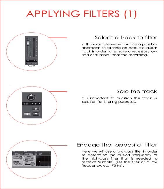
FILTERING
The filtering of non-musical content, e.g. ‘rumble’, commonly takes place before individual signals reach the multitrack machine, i.e. engineers frequently record microphone signals through high-pass filters, with a few obvious exceptions such as bass drums, floor-toms, etc. In some cases the filtering of spectral content may seem more appropriate when applied to the monitor (Mix B) path, allowing the material to be captured unprocessed onto the multitrack recorder while being mixed musically onto a two-track device.
As mentioned before, it is important for the production team to understand the role of the different elements of a song and their contribution to the creation of a musical ‘whole’. As an example, a track may have several instruments with good sounding low-end, e.g. bass drum, 808 bass drum, synth bass, bass guitar, etc., and a recordist may not be prepared to cut any of the ‘bottom’ on the way to the multitrack machine. In such circumstances, it would be advisable to filter the signals on the way to the two-track (monitor mix) recorder, so as to avoid an imbalance in the spectrum, i.e. the team would probably have to choose one or a couple of elements that would carry most of the low-end energy of the track.
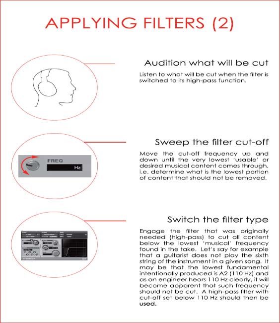
Determining Filter Cut-Off Frequency
The knowledge of musical instrument characteristics may help engineers determine the appropriate cut-off frequency for a given source, e.g. as a traditional acoustic guitar has E2 as its lowest open string, an engineer may set a high-pass filter to cut all content below approximately 82 Hz (remember that the cut-off frequency will be attenuated by 3 dB, so in this case it should be set lower than 82 Hz).
‘Rumble’ and Mixing
Engineers must always consider the negative effects of ‘rumble’ when mixing and remember that a ‘cluttered’ bottom end may keep low-frequency drivers (woofers and possibly sub-woofers) from moving in a compliant and focused way, i.e. if a driver is in constant (non-musical) motion it may have difficulty tracking more instantaneous low-frequency rich content, e.g. bass drums, etc.
LEVEL BALANCING
Level balancing is probably the single most important element in mixing (in fact, in the past mixing engineers were known as ‘balance engineers’). The challenge of balancing levels lies in the understanding of the roles and hierarchy of the individual elements of a production and the necessity to combine such elements into one cohesive, believable ‘picture’. In the early days of recording, such balance was achieved through the placement of musicians at different distances from a single transducer and the process of recording directly to cylinder or to disc did not call or allow for what we call mixing to take place. It was only through the advent of multitrack recording that it became possible for engineers to record individual sources in isolation and without consideration for their place in a production, i.e. all instruments could now be recorded at equal, ‘robust’ levels and the balance between signals could be adjusted during the creation of a monitor mix and/or at a separate mixdown stage.
It may be argued that the secret to level balancing lies in maximising the impact of the different elements of a mix while making sure that they ‘sit’ alongside each other without conflict. For this task, engineers may adopt one of the following two strategies:
1. Work with all signals simultaneously, trying to make them fit onto a ‘big picture’ from the onset.
2. Start the monitor mix with one or a few signals (usually the rhythm section) and add new elements individually or in small groups.
Although a number of seasoned professionals follow and defend the first approach confidently, others prefer to mix using the second one and it may be advisable for recordists to adopt the latter, as it may be easier to implement during multitracking, i.e. when crafting monitor mixes (due to the nature of sound checking) and it may help less experienced individuals learn the basics of signal summing.
Signal Summing
It is important for recordists to understand how the elements of a production will interact when mixed to two channels and what such interaction means in terms of dynamic range. As we have seen previously, the lowest clipping point between the different components of a chain should be taken as the system’s ceiling (unless gross distortion is desired). Once this figure is established, it is the task of the engineer to decide how the individual musical sources will combine and fill the available dynamic span.
It may be helpful to point out what happens when multiple signals are sent to a common destination.
• When two identical signals are summed the level reading at the summing point will be 6 dB higher than what would correspond to a single instance of the signal, e.g. when summed, two identical 1 kHz sine waves at – 20 dBFS will combine onto a 1 kHz sine wave at – 14 dBFS.
• When two non-identical signals are summed, as long as the signals are mostly coherent in polarity, the level reading at the summing point will be higher than what each individual signal would produce separately. The magnitude of the difference will depend on the degree of coherence and on the envelope of the two signals, e.g. a bass drum and a bass guitar peaking at – 6 dBFS individually may produce a combined reading approaching 0 dBFS.
With the previous points in mind, engineers should always consider what is going to happen to a monitor mix as multiple sources are brought into the picture and this should guide their early decisions regarding levels, e.g. it would make very little sense to start a mix to two-track with a bass drum producing a reading of – 6 dB under clipping if a few other elements, such as a drum machine, a bass guitar, etc., will be playing similar rhythmical patterns at comparable levels (possibly hitting downbeats together).
Individuals required to create a monitor mix while multitracking can benefit greatly from considering instrumentation and thinking ahead in terms of headroom. By bearing the basic principles of signal summing in mind, recordists may set the monitor path or DAW output faders (if mixing in the box) at reasonable, non-arbitrary levels immediately after setting the gain structure to multitrack, i.e. after checking multitrack return signals at unity gain, recordists may set the return path or output faders at what would seem to be sensible ‘mix’ levels. With this approach, as all instruments are sound-checked sequentially, the first components of the mix , e.g. the rhythm section, may serve as the anchor point in relation to which all other sources must conform and all components may be combined quickly into a cohesive, believable sonic landscape.
PANNING
Mixing in stereo makes it possible for engineers to distribute the energy of a production spatially (in the horizontal plane) and achieve a clarity that is arguably more difficult to attain in mono. Through the use of panning, sound sources that would otherwise fight for space in a mix may be set so they interact positively without the need for equalisation.
Although the spatial distribution of instruments in a mix should be determined on a case-by-case basis, certain elements, e.g. main vocals, bass drum and bass guitar, are consistently assigned to a predetermined position in traditional popular music, namely the centre between speakers. This is a characteristic inherited from the vinyl cutting days, where the side panning of high-energy components would commonly equate to mechanical problems during reproduction, e.g. the stylus would skip.
As a general rule in pop music, engineers should try to generate a balance between the two channels of a mix. This will ensure that listeners will not feel that they are being ‘pulled’ towards one of the two sides of the production, which can be distracting. In order to achieve this, one may simply think of sound sources as working in pairs and try to mirror them within the stereo spectrum. As an example, if an electric guitar is panned left, another instrument, e.g. an electric piano can be placed on the right to counterbalance the energy of the former.
If we continue exploring the approach described in the preceding level balancing section, as recordists sound check, not only can they set ‘multitrack return’ levels to a ‘mix position’, but they can also start distributing the energy of the Mix Between the left and the right of the monitor mix. Of course such distribution of elements can (and should) be re-evaluated as sessions progress, yet having an initial even image can help the production team assess the different elements of a production and verify that they are fulfilling their role in the mix.
Levels and Panning During Sound-Check
The following steps describe how a recordist may work with multitrack return signals during sound-check:
• Audition an element in isolation (channel or ‘to multitrack’)
• Set the correct gain structure to the multitrack recorder
• Audition the multitrack return signal at unity gain
• Set the multitrack return faders at a reasonable position (thinking in terms of the headroom of the two-track recorder)
• Pan the signal to an ‘instinctive’ position in the mix
• Think of another ideal element to be panned symmetrically, i.e. opposite (make a note), e.g. if the original element was a hi-hat, consider panning a shaker or a rhythm guitar opposite to it.
Panning Laws
When signals are routed to a stereo destination and panned to the centre, they will be sent with equal energy to both left and right outputs or channels. This should normally equate to a boost in overall level, as we would effectively be monitoring two versions of the same signal.
Panning laws were devised in order to avoid undesired or excessive alterations in level resulting from changes in panning. Such laws are not universal and they may attenuate centre-panned signals by 6, 4.5, 3, etc. dB (or side channels boosted by the same amount). This results from different views regarding the impact of side refections on overall levels, i.e. some theorists believe that side reflections always affect side-panned signals, so centre components should not be attenuated by the full amount of decibels that would seem intuitive.
Most DAWs offer the user the possibility of choosing the panning law to be used for a session.
EQUALISATION
Equalisation is commonly used to help improve clarity and balance in a mix. As we have seen, level balancing and panning can, and should, be used firstly for such purpose, although in many cases they may not be sufficient to generate the ideal equilibrium for a production.
The distribution of sound energy within the working frequency spectrum (broadly speaking between 20 Hz and 20 kHz) may be described as a ‘vertical’ process standing counterpart to the horizontal spread of panning. Such view may help engineers understand that the process of distributing energy within a mix is multidimensional and, as a result, all elements should be analysed accordingly. As an analogy, one may think of the sound generated by an instrument as a number of boxes stacked vertically with contents that vary in weight or volume. The number of such boxes is determined by the number of the instrument’s distinct bands, e.g. it may seem appropriate to split an instrument into three (lows, mids and highs) or four (lows, low-mids, high-mids and highs) bands. During mixing, the contents of all the different instruments’ ‘boxes’ must be transplanted onto a single set of shared ‘storage drawers’ (the mix), which must be filled evenly and with no overflow. Once again, engineers may attempt to create such balance working with a few elements in isolation, although at this point the interaction between the components of a mix must be considered from the onset.
It is important to note that some recordists will use equalisation as a means to improve the sound of a given source. In such cases, the use of different backline, microphones and techniques (including playing) will invariably yield better results and should be attempted first.
Soloing Equalised Elements
Engineers may need to employ ‘unusual’ equalisation in order to get an instrument to ‘sit’ in the mix when working on busier sounding productions. This is due to the fact that a spectrally isolated element may cut more easily through the mix (even at lower levels). It is important in such circumstances that the aforementioned instrument is not auditioned or evaluated in isolation (via solo), as it will not sound ‘truthful’ to the source, i.e. engineers should discourage clients to solo elements that were shaped drastically to fit a production.
The following page contains a visual example of the EQ ‘boxes’ analogy.
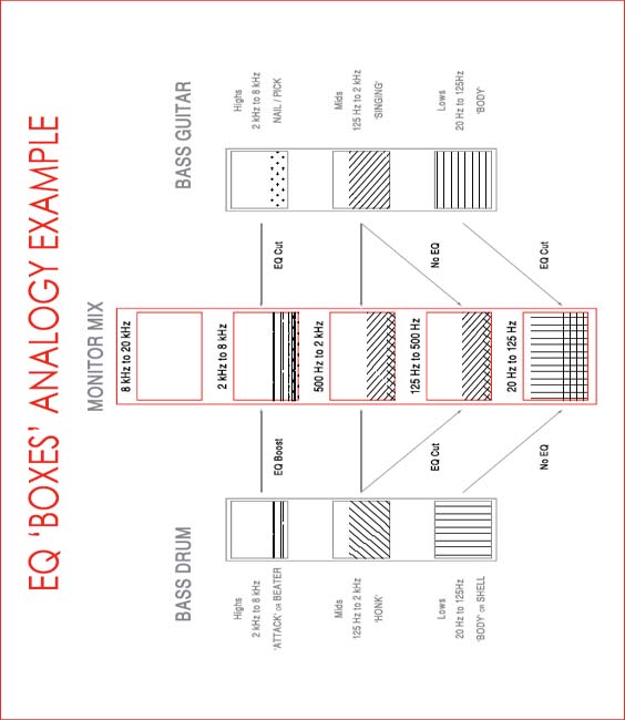
NB All the cuts and boosts in the previous example are localised, i.e. they do not span over the entire band.
DYNAMIC RANGE PROCESSING
There are two main reasons that justify the use of dynamics processing:
1. The necessity to control the dynamic range of a signal
2. The desire to shape the sound of an instrument or source.
It is important to note that the first purpose is based on a need, while the second one is not. As a result, engineers reaching for a compressor, limiter, expander or gate must first establish if their use is truly necessary and, if not, what the expected outcomes of their employment are.
Compressors / Limiters
In order to determine whether a sound source needs compression or limiting due to its dynamic range, one may simply audition it throughout a production and determine whether its place in the mix seems stable or if the source seems to fluctuate excessively in level, moving in and out of the picture (this test may be particularly effective when performed at low monitoring levels). If level changes are detected, but they occur sparsely, e.g. between different sections of a song, gentle fader riding or RMS-based compression may be sufficient to control undesirable fluctuations. If level changes are pronounced and fast occurring, a combination of fader riding (automation) and peak-based compression may be required and in radical circumstances, e.g. when an instrument such as a bass guitar is expected to ‘anchor’ a Mix By not moving at all, limiting may be more suitable to control dynamic range.
Crest Factor and Compression
If the difference between the peak and the RMS average of a signal (the crest factor) is small, the use of compression will most likely bring no benefits (unless extreme processing is desired). If alternatively the crest factor of a signal is significant (over 20 dB), the material may benefit from the use of dynamic control. This may facilitate the mixing process in pop music as different elements are easier to place in the mix and will not shift exaggeratedly through a production.
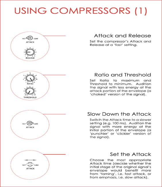
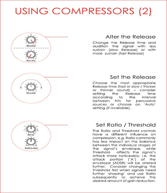
A Musical Approach to Setting Compression Parameters
Regardless of whether a compressor is being used to control dynamic range or to shape signals, it is advisable for whoever is using such a device to examine the different envelope stages of the material that will be processed, i.e. its attack, decay, sustain and release. As a suggested approach to setting compression parameters, one could start by trying to determine whether a sound source would benefit from having more or less attack and/or more or less sustain, i.e. whether if forced to choose a technician would prefer a punchier, duller, thicker or thinner sound. Based on such observations, one may approach compression controls in a logical way and avoid the arbitrary use of dynamic range processing.
When compressors are used for the control dynamic range, they should produce undetectable results. This principle is commonly misunderstood by some novices, who feel that compressors are not doing anything unless their effects are clearly audible.
The following pages describe a suggested procedure that may help recordists use compression in a ‘musical’ way. It is important to point out that this procedure is more relevant and clearer when analogue devices are used (due to their less extreme attack, release and ratio settings) and when percussive sound sources are selected for processing, e.g. bass drum or snare.
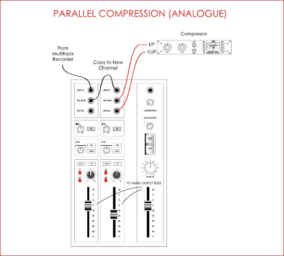
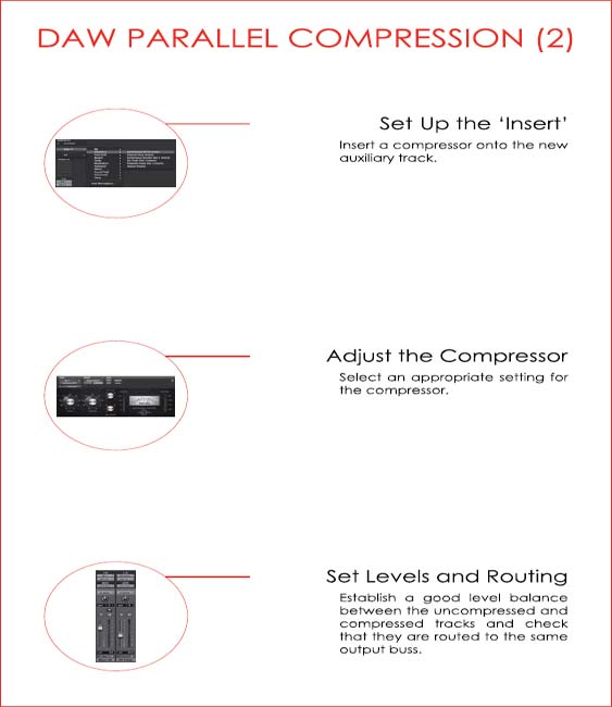
Parallel Compression
Signals may be processed in series, where the original material is altered, or in parallel where a new processed version is created and does not replace its source. Although most of the time dynamic range control seems more appropriate when applied in series (for which it was originally designed), in some circumstances engineers may find it more suitable to compress signals in parallel.
Parallel compression allows for low level components of a track to be brought up with less impact on the overall attributes of the signal, i.e. preserving the material’s transient content. This technique is commonly used to add ‘size’ and energy to drum recordings, where overhead or mono room microphone channels are copied and compressed at fairly extreme settings.

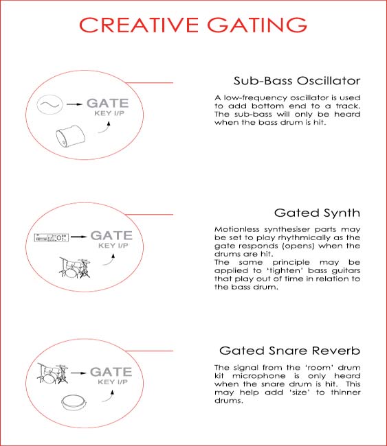
Gates / Expanders
Gates and expanders are rarely employed to process signals on their way to the multitrack recorder, as such form of dynamic range control is not commonly necessary and its misuse can lead to disastrous consequences. As far as mixing is concerned, gates and expanders are still found controlling dynamic range on occasion, although since the advent of the DAW and non-linear editing, where regions may be trimmed and levels automated, they are far more frequently used for creative purposes, such as key input (side-chain) based rhythmic gating, etc. It is important to point out that in the case of monitor mixes this must be performed quickly or simultaneously to multitracking, i.e. with no time for editing, gates may still play an important roll in ‘cleaning up’ tracks with microphone ‘leakage’, e.g. snare drum, tom-toms, etc.
Using Gates to Eliminate ‘Leakage’
The following is a quick guide to using gates to reduce the effects of microphone ‘leakage’:
Start with the gate set as follows:
• Range at the maximum setting
• Ratio at maximum setting (if using an expander/gate)
• Attack at fastest setting
• Release at fastest setting
• Threshold at maximum setting
• Hysteresys at 10 dB (if such control is offered).
Make the following adjustments:
• Decrease the threshold until the first signals start opening the gate (just the attack portion of the envelope – the signal should be ‘clicking’ now.
• Increase the attack time so the signal does not click anymore.
• Lower the threshold if necessary (if the initial portion of the signal’s envelope is being cut).
• Increase hold time until most of the signal envelope is going through the gate.
• Adjust the release setting so the signal decays before the first following ‘undesired’ signal goes through the gate.
‘Duckers’
A ‘ducker’ may be described as a gate with an inverted function, i.e. a device that attenuates signals when an input overshoots the threshold. Such devices are commonly used in broadcasting, where an announcer’s voice forces the background music’s level down.
In the absence of traditional ‘duckers’ (as gates that offer such function are becoming rare), engineers may use downward compressors for the same purpose, although it is important to note that the latter cannot apply a fixed amount of attenuation to signals in the same way that ‘duckers’ can (range).
Using Duckers with a Key Input Signal
Ensure to patch the key input appropriately and to engage the equivalent external key input function.
Start with the ducker set as follows:
• Range at the maximum setting
• Ratio at the maximum setting
• Attack at the fastest setting
• Release at the fastest setting
• Threshold at the maximum setting.
Make the following adjustments:
• Decrease the threshold level until the signal to be ducked ‘disappears’ when the key input signal is present.
• The signal should be clicking/pumping now.
• Increase the attack time so the signal does not click any more i.e. level reduction is applied in a musical fashion.
• Increase hold time so the signal to be ducked does not come up in level as the key input signal fluctuates briefly in amplitude, e.g. between voice-over words.
• Decrease the range so the ‘ducked’ signal does not become completely inaudible.
• Adjust the release setting so the signal returns to unit gain appropriately after the necessary ducking is achieved.
The following pages contain examples of creative uses for gating and ducking.

Processing Order
Some mixing consoles make it possible for the user to source the insert send signal from a pre or post-EQ position. This can be particularly helpful when compression is to be applied in series with equalisation, as in the examples below:
• EQ Followed by Compression
This is the ideal set-up when the dynamic range of material must be controlled within a strict range. Post-equaliser compression ensures that possible EQ boosts will not undermine the control over dynamics.
This order of serial processing may also be explored artistically where the user purposefully overdrives the compressor (through a boost of an ‘aggressive’ range).
• Compression Followed by EQ
Compression can alter the spectrum of low-end rich sound sources significantly and in the case of bass guitars and bass drums this may lead to signals that are dynamically controlled at the expense of size and tone. In such circumstances, the use of equalisation post-compression may help restore the ‘size’ of bass-heavy signals.
• EQ Followed by Gating
The use of equalisation may help desensitise a gate to portions or elements of a signal, e.g. a high pass filter may be applied to a snare drum channel so that bass drum leakage does not cause the gate to open.
• Gating Followed by EQ
Some signals require gating for the removal of ‘leakage’, while also benefiting from the use of equalisation. In some circumstances, the use of EQ may make the gating process difficult to achieve effectively, so dynamic range processing should ideally precede the use of EQ. As an example, a snare drum track may sound ‘dull’ and contain hi-hat ‘leakage’. If this is the case technicians should gate the signal first and apply EQ subsequently.
EFFECTS PROCESSING
The use of effects processing during the creation of monitor mixes is largely seen as a matter of creativity, although a few important points should be considered:
• Artists will most likely expect to hear similar effects to those they heard through their headphones during recording when they audition the monitor mix (but not necessarily with the same intensity or at the same level).
• Time-based effects can add depth to a mix, making the latter more three-dimensional.
• Time-based effects may generate a sense of shared performance space to productions that rely on extensive overdubbing.
• The use of short delays may help ‘thicken’ sounds more efficiently than equalisation would.
Time-Based Effects and Mix Depth
The bussing of signals to a common effects processor may help engineers add a real performance ‘feel’ and depth to productions based on overdubs and/or recorded in very ‘dry’ environments. This can work particularly well with instruments that complement each other, e.g. snare drums and percussive rhythm guitars, when these are sent to the same reverb unit. Engineers should ideally use a stereo auxiliary buss to feed the effects processor, ensuring to pan both the feed to the main buss and to the ‘aux’ consistently, e.g. if the ‘dry’ signal of an instrument is panned to the left of the main mix it should ideally also be (somewhat) panned to the left of the reverb unit’s input, making the overall image of the instrument in the mix credible or realistic.
Haas Effect-Based Delays
In the 1950s Helmut Haas established that if multiple versions of a given sound are offset by a small time delay, the first wavefront to arrive at the listener’s position will, in most circumstances, determine localisation. This phenomenon is known as the Precedent Effect, Law of the First Wavefront or Haas Effect and it may be explored in mixing so as to increase the dimension of sounds. The use of short (20 to 30 millisecond) delays may be considerably more efficient in making signals appear more robust than the use of equalisation.

ADT
In the 1960s, Abbey Road studios’ innovative engineer Ken Scott devised a way to double up vocal tracks without the need for the performers to record multiple takes of the same part. The process involved two tape machines with unevenly spaced ‘record’ (‘sync’) and ‘repro’ heads, running at different speeds.
The effect known as ‘artificial double tracking’ or ADT may be approximated through the use of digital delays (set at a time of around 40 ms) and the effect is particularly convincing if the ‘dry’ and ‘wet’ versions of the signal are panned separately and the delay times fluctuate very slightly and randomly (emulating the varispeed of tape machine transport).