THE TOOLS
Advanced technicians from different fields seem to share the ability to select and use their tools skilfully, achieving consistent high-quality results. Such proficiency commonly results from years of experience, although it may be mistaken for a natural talent. In fact, technicians that develop their expertise through practice may find it difficult to rationalise or explain their actions, as production appears progressively more intuitive and effortless.
Although technical knowledge alone does not guarantee successful results, it may provide the necessary foundation upon which experience may be built. With this in mind, it seems advisable for recordists to study the tools they work with in detail, setting out guidelines for their selection and use. To some, this process could initially be based on familiarity or external influences, e.g. using Neumann microphones to record vocals, as Geoff Emerick did to record the Beatles, although ultimately it would be more appropriate for such important decisions to be based on a balance between intuition, scientific knowledge, experience and the desire to experiment.
The following sections present possible strategies for the selection of recording tools.
MICROPHONES
Microphones are broadly described as transducers or converters of energy. These, alongside loudspeakers, arguably constitute the most important elements in the audio chain, as both perform vital roles at the two ends of the signal path. While the microphone selection process may seem simple and spontaneous to some, it is not uncommon for recording engineers to spend considerable time and effort to ensure the best device is selected for each given job.
While the criteria influencing the choice of transducers may extend well beyond the realm of technical specifications, for the sake of objectivity four main factors are presented here as most important for microphone selection. These are:
• Transducer type – Bias vs. Fidelity
• Diaphragm size – Output sensitivity / Bias vs. Fidelity
• Directionality – Separation
• Construction – Physical considerations.
MICROPHONE SELECTION CRITERION 1: TRANSDUCER TYPE (BIAS vs. FIDELITY)
A basic understanding of the physical principles of transduction on the part of the reader is expected in this section, where the main objective is to discuss the general characteristics and merits of different transducer types, which are described next.
Transducers may be classified according to their operating principle, falling into the following key groups:
• Electro-dynamic or dynamic (moving coil, ribbon and printed ribbon)
• Condenser (Including electret condenser and PZM or boundary)
• Piezo or crystal-based
• Other.
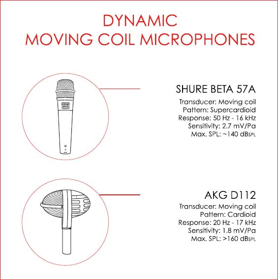
Moving Coil-Based Dynamic Microphones
Moving coil microphones:
• Have relatively heavy moving parts and therefore present slower transient response and lower sensitivity to small variations in pressure (less detailed pickup).
• Have limited high-frequency response.
• Are commonly not ‘transparent’, i.e. they generally add ‘colour’ in the high-mid frequency range (~ 5 kHz to 10 kHz).
• Are robust and can handle high sound pressure levels.
• Are effective when placed in close proximity to the sound source.
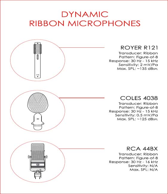
Ribbon-Based Dynamic Microphones
Ribbon microphones:
• Have light moving parts and are sensitive to small variations in pressure, commonly presenting a more accurate transient response than moving coil microphones.
• Usually add ‘colour’ to recordings (roll-off of high frequencies).
• May sound ‘thin’ if placed distant from sound sources.
• Present a pronounced bass response when placed close to performers (‘proximity effect’).
• Are normally more fragile than moving coil microphones.
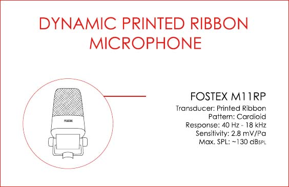
Printed Ribbon-Based (Regulated Phase) Microphones
In the less popular ‘printed ribbon’ or regulated phase transducer, an aluminium spiral ribbon is mounted onto a plastic (mylar) diaphragm, which is in turn placed between two ring magnets. Regulated phase transducers:
• Have light moving parts (good transient response).
• Tend to be more resilient than traditional ribbon microphones.
The following illustrations depict examples of moving coil and ribbon-based dynamic microphones that are commonly used in music production. The regulated phase example is included here for historical / illustrative purposes, as this type of transducer is not currently popular and its use has become somewhat rare.

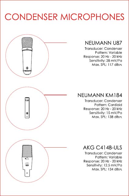
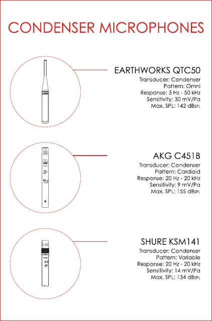
Condenser Microphones
Condenser microphones rely on the varying distance between the two plates of a capacitor to operate (variable capacitance).
Condenser-based transducers:
• Have very light moving parts, which allow for a fast transient response and high sensitivity.
• Offer an extended high-frequency response.
• Can be extremely transparent (flat frequency response).
• Commonly require a (phantom) power supply to operate.
• Frequently incorporate a built-in amplifier section (valve or FET), used to boost output gain and convert (lower) impedance.
• May be placed at greater distances from sound sources.
• Are commonly fragile.
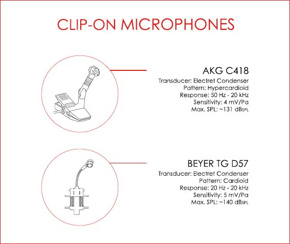
Electret Condenser Microphones
The difference between electret and ‘true’ condenser microphones lies in the method used for diaphragm polarisation. In broad practical terms, the permanently polarised backplate of ‘electrets’ makes it possible to construct of a less expensive and more resilient microphone that may be placed in extreme proximity to sound sources, e.g. miniature instrument clip-on condenser microphones.
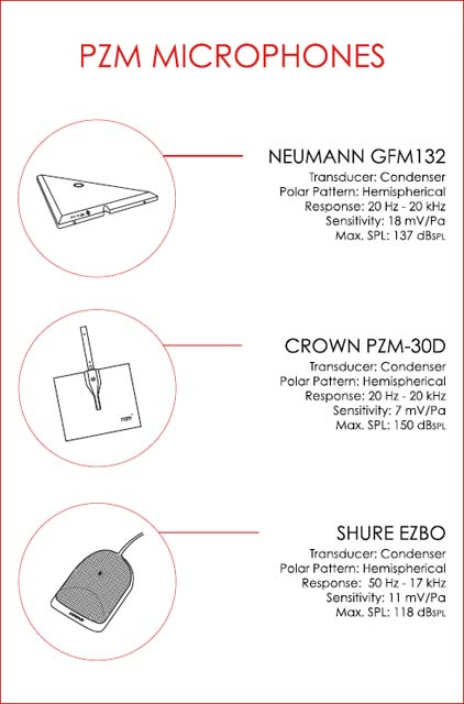
Pressure Zone Microphones
Pressure zone microphones (PZM), also known as ‘boundary microphones’ were developed in an attempt to avoid phase interference caused by hard surface reflections (in close proximity to the sound source).
In pressure zone microphones a miniature condenser capsule is found at a very short distance from a metal boundary, which is commonly placed on reflective surfaces, such as walls, piano lids, etc.
Boundary microphones:
• Do not present off-axis colouration.
• Present an even frequency response and high sensitivity.
• Commonly offer good signal to noise ratios.
Valve (Tube) Microphones
The built-in amplifier found in condenser microphones may rely on valve or transistor-based circuitry to operate. Valve-based condensers typically require a dedicated power supply unit, capable of delivering voltages in the 100 V range and are usually connected to their power supplies via multi-pin (five to seven-pin) cables.
It is advisable for recordists to power their valve-based (tube) condenser microphones at least one hour before sessions, as such devices commonly require time to reach a consistent, stable level of operation.
Digital Microphones
Digital microphones are commonly comprised of a regular condenser capsule followed by an analogue to digital converter. This allows for the conversion of audio at an early stage, which helps minimise the degradation of signals. Some digital microphones incorporate extra features such as peak limiting and remote control over polar pattern selection, input pad, pass-filter, etc.
Phantom Power
Some microphones require a supply of a DC voltage to operate. This supply is commonly delivered at 48 volts DC via XLR pins two and three and it is used to power the built-in amplifier used for impedance matching (following the transducer). This improves signal transmission over longer cable runs. In the case of non-electret (true) condenser microphones, phantom power is also used to polarise the backplate of the capsule.
Recordists should be very careful when using phantom power, where the following rules must be observed:
• Always mute the control room monitors before switching phantom power on or off.
• Avoid sending phantom power to microphones that do not require a DC supply, as these may get damaged, e.g. through cross-patching (patchbays).
• Be aware of the danger of using gender changer cables and avoid the presence of phantom power in male XLR connectors (due to the risk of electric shock).
• Patch all XLR cables onto their respective microphones prior to switching phantom power on.
• Turn phantom power off before disconnecting all condenser microphones.
Always neutralise mixing consoles after sessions, ensuring phantom power is off in all channels.
The following pages contain examples of condenser microphones that are commonly used in music production.

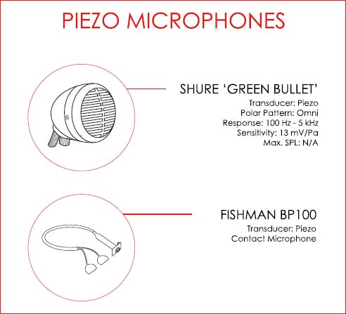
Piezo Microphones
Piezo or crystal-based capsules are commonly employed in ‘contact’ microphones or acoustic instrument ‘pick-ups’.
Piezo microphones:
• Are commonly biased towards high / high-mid pick up, with poor low and very high-frequency representation.
• Minimize the effect of feedback originating from backline.
• Work well to capture signals for subsequent replacement, e.g. snare drum contact microphones.
OTHER MICROPHONES
Other types of microphone exist, e.g. carbon, fibre-optic, laser, etc. although these are not commonly used in music applications at present.
MICROPHONE SELECTION CRITERION 2: DIAPHRAGM SIZE (OUTPUT SENSITIVITY / FIDELITY)
The influence of diaphragm size over microphone performance varies according to transducer type. Most authors question the use of large capsules in dynamic microphones, arguing that due to operating principle the benefits of such implementation are minimal, if not negligible. A few designers, such as Bob Heil, believe on the other hand that a larger diaphragm equates to improved transient response, even in the case of moving coil microphones, as long as the parts are made light enough. Regardless of the debate, capsule dimensions have a more tangible effect in the case of condenser microphones, where:
1. Microphone sensitivity is commonly proportional to diaphragm size.
2. Off-axis pickup fidelity is inversely proportional to diaphragm size.
As a general rule, the use of a larger sized diaphragm should be considered when significantly small variations in pressure must be captured with great detail, e.g. vocal performances where minute ‘mouth’ noises may add intimacy to a recording. At the same time, the use of small diaphragm transducers is indicated when off-axis sounds must be captured with great fidelity, e.g. large ensembles recorded with few microphones.
It is important to note that sound engineering authors do not seem to agree on the impact of diaphragm size over bandwidth. Considering the series of factors that may influence a microphone’s response, e.g. diaphragm tension, mass density and the sizes of the internal cavity and of the static pressure equalization vent, it does not seem reasonable to assume there is a simple causal relationship between diaphragm size and bandwidth of pickup, i.e. recordists should always check a microphone’s frequency response graph.
MICROPHONE SELECTION CRITERION 3: DIRECTIONALITY (SEPARATION)
Two important questions provide the basis for this criterion:
1. How much separation between channels is required?
2. How much natural reverberation is desired?
If in answering the first question it is established that a great degree of separation is required, omnidirectional or bi-directional microphones should be avoided or used with caution (unless the physical isolation between performers in the studio is achievable and practical). In such case, directional microphones, e.g. hypo, super, hyper or standard cardioid transducers represent a better choice, as these may offer considerable rejection of unwanted sounds. This is particularly important in the case of projects where extensive editing may be required, i.e. productions in which song arrangement or structure might change and different instrumental parts may need to be moved or copied between sections.
As far as the second question is concerned, transducers with wider pick-up patterns, e.g. omni and hypocardioid, may capture the natural sound of an environment with more accuracy. In favourable recording settings, the use of non-directional microphones may prove invaluable and should be explored.
It is important to mention that directionality will also affect frequency response (and therefore ‘fidelity’) for both on and off-axis sound pick-up.
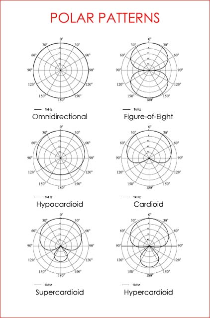
Polar Patterns
Polar pattern graphs may display one (1 kHz) or many curves, e.g. 100 Hz, 10 kHz, etc., as microphones do not present a constant pick-up pattern across the audio spectrum, i.e. polar patterns change according to frequency and microphones become less directional when handling material at the extremes of range.
1. Omnidirectional microphones:
• Are equally sensitive to sound arriving from all directions.
• Provide the flattest frequency response with no proximity effect (if not based on dual cardioid capsules combined).
• Are less prone to the pick up of rumble and wind sounds.
• Present the least coloration of off-axis sounds.
2. Bi-Directional / microphones:
• Are most sensitive to sounds arriving from two directions, i.e. the front and the back of the diaphragm.
• Exhibit a prominent ‘proximity effect’.
3. Unidirectional microphones (Hypo / Super / Hyper / Cardioid):
• Are most sensitive to sounds arriving from one direction (on axis).
• Exhibit the ‘proximity effect’.
The following pages describe common microphone polar patterns, including a brief examination of their use.


Proximity Effect
The so-called ‘proximity effect’ may be described as a directional microphone’s increase in bass response as the sound source approaches the diaphragm. This effect is commonly explored artistically, where the signal from ‘thin’ sounding performers is enhanced through close microphone placement.
MICROPHONE SELECTION CRITERION 4: CONSTRUCTION (PHYSICAL CONSIDERATIONS)
This last criterion is the simplest, where selection is influenced or dictated by the overall physical dimension of the microphone, e.g. when difficult placement or restricted access may require the use of a transducer of small size. In such circumstances a compromise may be required, where sound quality may not be given priority over other criteria.

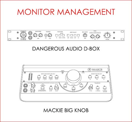
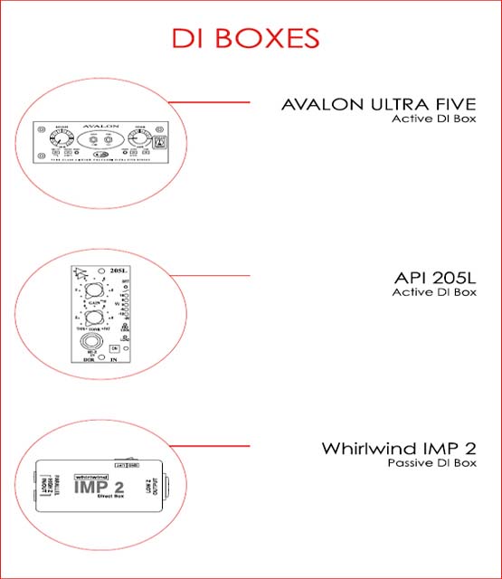
DI / DIRECT INJECTION BOXES
A DI or direct injection box is a device that allows for high impedance electric or electronic instruments to be connected to low impedance inputs, e.g. through direct injection, the output of an electric bass or guitar may be fed to a console’s microphone input, bypassing the use of an instrument amplifier (backline) and of a microphone.
Passive DI boxes lower the impedance of the source (the instrument) through the use of transformers. The latter also allow for the balancing of signals, i.e. a conversion from unbalanced ‘jack’ to balanced XLR connections. Active DI boxes utilise electronic circuitry to achieve the same impedance conversion as passive devices, while offering improved fidelity, i.e. higher gain and wider frequency response. Such devices are commonly fed by phantom power or by batteries.
DI boxes make it possible for:
• High-impedance electric or electronic instruments to be recorded without backline amplification.
• Instruments to be recorded in extreme isolation.
• Signals to be transmitted over longer distances (through balancing).
• The subsequent ‘re-amping’ of instrument signals.
It is important to point out that active direct injection boxes may not be perceived as ‘superior’ to passive devices by many musicians who prefer using the latter.
Parallel Outputs
It is common for DI boxes to offer a ‘jack’ connector parallel output patch point on their ‘input’ side, allowing for the simultaneous feed of a console and of an instrument amplifier. In such cases it is highly recommended for engineers to record both signals, as this may allow for the combining of the two tracks during mixdown.

Impedance
Impedance is total opposition to current flow, i.e. the combination of resistance (frequency independent) and reactance (frequency dependent) opposition. Output impedance may be broadly described as a measure of how difficult it is to ‘extract’ signals from an electric or electronic sound source.
Ideally, a lower output impedance should meet a higher input impedance, e.g. microphones with impedance ranging from 50 to 600 ohms should normally feed preamplifiers with impedances ranging from 2000 to 5000 ohms. This helps ensure that signals will reach the input or ‘load’ with fidelity. DI boxes lower the high output impedance of electric instruments so they may feed microphone preamplifers directly (a 104 to 102 range conversion).
Balancing
Balancing is an elegant solution for the problem of electromagnetic interference. In balanced connections, an original audio signal (‘hot’) and a polarity-inverted copy (‘cold’) travel along a twisted pair of conductors. In the case of electromagnetic interference, both conductors are equally affected and the rejection of unwanted sounds is made possible through the polarity inversion of the ‘cold’ component at the destination (or input).
It is important to note that in the case of short cable runs, the use of balanced connections may not be necessary or justifiable.
Ground ‘Lifting’
DI boxes commonly offer a ‘ground lift’ option. This can be useful when an instrument, e.g. a bass, is connected simultaneously to a mixing console and to an amplifier (backline) at different potentials to the ground. Such arrangement can lead to an AC current flowing in the shield of the conductor, which may ultimately lead to 50 or 60 Hz cycle ‘hum’. The ground lift function decouples the input and the output of the circuit electronically, commonly reducing or eliminating ‘hum’. DI boxes should be set originally on their ‘ground’ position and only set onto ‘lift’ in the case of a ground loop problem.
Valve (Tube) DI Boxes
Valve (tube) DI boxes utilise electronic circuitry to lower impedance and to amplify and balance signals.

ANALOGUE AUDIO CABLES / CONNECTORS
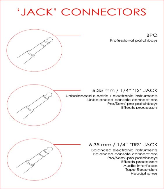
‘Jack’ / Phone
The following are types of ‘jack’ or phone connectors:
• 3.5 mm / 1/8” Jack or ‘TS’ ‘Minijack’ Two terminals: tip and sleeve
• 3.5 mm / 1/8” Jack or ‘TRS’ ‘Minijack’ Three terminals: tip, ring and sleeve
• Bantam / TT Three terminals: tip, ring and sleeve – ‘TRS’
• BPO (BPO316) / ‘B-gauge’ Three terminals: tip, ring and sleeve – ‘TRS’
• 6.35 mm / 1/4” Jack ‘TS’ ‘A-gauge’ Two terminals: tip and sleeve
• 6.35 mm / 1/4” Jack ‘TRS’ ‘A-gauge’ Three terminals: tip, ring and sleeve
• 2.5 mm Jack (not commonly used in current manufacturing).

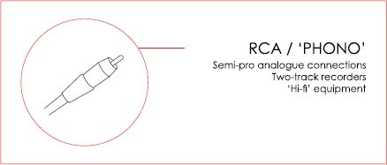
RCA / Phono
RCA or ‘phono’ connectors commonly contain two terminals (tip and sleeve – ‘TS’).
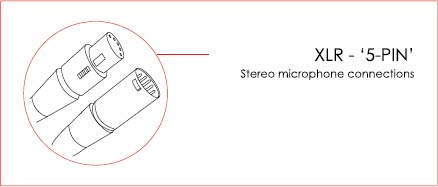
XLR / Cannon
XLR or Cannon connectors / cables are available in two, three, five and seven-pin configurations.


5-Pin XLR Connectors
5-pin XLR connectors are employed by some dual-capsule stereo microphones.
7-Pin XLR Connectors
7-pin XLR connectors are used for the connection of some valve microphones to their corresponding power supplies.
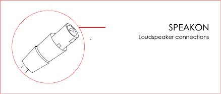
Speakon
There are three common types of speakon connectors:
NL2 – containing two terminals.
NL4 – containing four terminals.
NL8 – containing eight terminals.
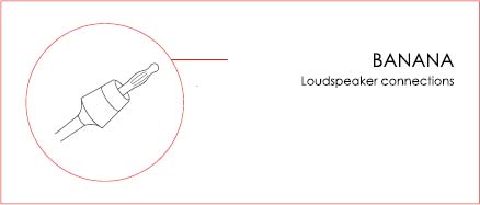
‘Banana’
‘Banana’ connectors contain one terminal.
D-Subminiature / D-Sub
There are several types of multi-pin D-subminiature connectors, e.g. DE9, DA15, DB25, DE26, DC37, DD50. The most common type of audio D-sub connector is the DB25, which contains 25 terminals.

EDAC / ELCO
EDAC or ELCO connectors are available in 20, 38, 56, 90 and 120-pin configurations.
Shielding
Metallic shielding (foil or braided) is commonly employed in audio cable manufacturing in an attempt to minimise the effects of noise. Shielded cables may be coaxial, triaxial or quadraxial depending on their conductor/shield configuration.
Cable Runs
Recordists must aim to use audio cables of suitable short length, laying them away from current carrying conductors, i.e. power cables, in order to:
• Minimise possible electromagnetic interference (especially on unbalanced lines).
• Avoid high-frequency roll-off (due to capacitance, where a long cable may act as a filter).
Any unavoidable extra cable length (‘slack’) must be laid on a ‘figure-of-8’ pattern for the reduction of the effects of electromagnetic interference, as improperly wound cables may act as ‘aerials’ and/ or high-cut filters.
If an overlap between audio and electrical cables is unavoidable, these should be set at a 90˚ angle, so the effects of interference / induction are minimised.
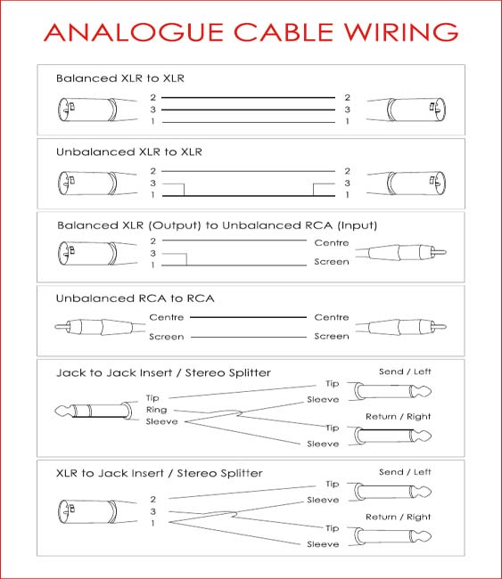
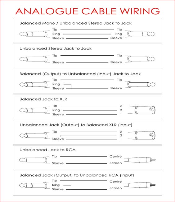
It is important for recordists to be able to assemble audio cables by soldering conductors to their respective connector terminals. Soldering is an invaluable skill, particularly for those working in isolated residential music production environments. The following pages describe the conductor / connector configuration for audio cables that are commonly used in music production.
NB All balanced output to unbalanced input connections depicted here correspond to impedance-balanced or transformer-based balanced devices feeding unbalanced inputs. In the case of active-based balanced devices feeding unbalanced inputs, the ‘ring’ of ‘jack’ connectors or ‘pin-3’ of XLR connectors should be left unconnected or ‘floated’. All unbalanced feeds to balanced inputs should use 3 conductor cables and incorporate a ‘cold’ to ‘ground’ link on the output side only.
DIGITAL AUDIO CABLES / CONNECTORS
TDIF (Tascam Digital Interface)
TDIF cables commonly terminate at 25-pin D-Sub connectors.
S/PDIF (Sony / Phillips Digital Interface)
S/PIDF protocol employs either coaxial low impedance (75 ohms) cables and RCA connectors, or fibre-optic cables and TOSLINK connectors.
ADAT Lightpipe
ADAT Lightpipe utilises fibre-optic cables and TOSLINK connectors.
AES / EBU
AES/EBU digital cables comprise low impedance (110 ohms) conductors that commonly terminate at XLR 3-pin or D-Sub connectors.
MADI
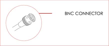
The MADI protocol employs low impedance (75 ohms) conductors and BNC connectors or, less commonly, multimode fibre-optic cables.
OTHER CABLES / CONNECTORS
Word Clock
Word clock cables utilise low impedance (75 ohms) conductors and BNC connectors.
Word Clock Termination
Some digital device set-ups require word clock ‘termination’ in order to avoid cable reflection and possibly ‘jitter’. Termination is achieved through the use of BNC ‘T’ connectors in conjunction with 75-ohm termination plugs. Users should check operation manuals to establish whether a chain requires external termination.
MIDI
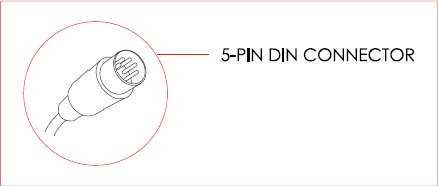
MIDI cables utilise three conductors and 5-pin DIN connectors, hence only three of the five pins are wired (pins 2, 4 and 5). MIDI cables should run for a maximum of 15 metres or 50 feet approximately.
MIDI Through XLR / TRS Cables
Some recording sessions may require the transmission of MIDI signals between live and control rooms. In such cases, it may be necessary to use XLR or TRS ‘jack’ connections, as most wall boxes do not offer 5-pin connections. When wiring a 5-pin DIN to XLR or ‘jack’ lead, the three middle DIN pins (2, 4 and 5) should be linked to the three terminals of the XLR / ‘jack’ connector. The transmission of data should work as long as the configuration is kept consistent.
The following is a possible way to wire a 5-pin DIN to XLR or TRS cable: Pin 4 of 5-Pin DIN to pin 2 of XLR or ‘tip’ of TRS ‘jack’
Pin 5 of 5-Pin DIN to pin 3 of XLR or ‘ring’ of TRS ‘jack’
Pin 2 of 5-Pin DIN to pin 1 of XLR or ‘sleeve’ of TRS ‘jack’
NB Such cables should not exceed approximately 2 metres or 6.5 feet in length.
MICROPHONE PREAMPLIFIERS
The main role of the microphone preamplifier is to raise microphone level signals to line level, although some units may offer extra features such as equalisation and compression. Microphone preamps differ in sound and while some devices may be broadly described as ‘transparent’, others alter the nature of audio material noticeably. In addition to that, equipment deemed as ‘transparent’ will commonly respond to quiet and loud sounds in a non-linear fashion, e.g. with increasing harmonic distortion.
A preamp’s alteration of timbre must not necessarily be seen as a negative side effect of amplification, as experienced engineers frequently attempt to ‘shape’ microphone signals before routing them to the multitrack recorder, e.g. via the use of equalisation. With that in mind, it appears as a sensible procedure for recordists to audition a few different preamplification units and to do so at ‘clean’, i.e. conservative input signals, and at higher, ‘overdriven’ levels before committing to a signal chain.
Harmonic Distortion
Preamplifiers, as all other signal processors, add harmonic content to their input signal. The level and nature of the added harmonics or distortion is an important factor influencing the efficiency and the perceived quality of devices.
It is not uncommon for engineers to associate pleasing or ‘musical’ lower-order even harmonics with valve-based equipment, while linking ‘harsher’ odd harmonic content to solid-state technology. It is true that older valve-based devices have a tendency to generate ‘rich’ even harmonic content, although it is important to note that this is largely due to the topology of such equipment (class ‘A’). ‘Near-clipping’ or ‘upper headroom’ checks are a simple way to investigate the suitability of harmonic and dynamic distortion to the audio material and as a way to assess the impact of noise generated at extremes of operation.
Microphone Preamplifier Noise Floor
The terminating of the input of a preamplifier, i.e. the connecting or ‘shorting’ of pins 2 and 3 at the input stage, is a quick way to determine the noise floor of a given device. Technicians should ideally use a male XLR connector with a 200-ohm resistor wired in series between the two pins (2 and 3) for this type of testing, as this should present the preamp with the equivalent output impedance of an ‘average’ dynamic microphone.
Variable Impedance
Some preamplifiers offer user modifiable control over input impedance. Such control may be continuous or discrete (few values) and it may have a significant impact over sound quality in circumstances when high impedance microphones, e.g. some ribbon models, are connected to the preamplifier via long cable runs. In such cases, a preamp high impedance setting may be recommended, as it may make signals seem ‘bigger’ or less ‘thin’ (more low-end content). NB the altering of input impedance should have very little impact on the signal of condenser microphones.
Suggested Microphone Preamplifier Evaluation Procedure
The process of evaluating the suitability of microphone preamplification may appear arbitrary to recordists with less experience, although it is possible for a simple methodical approach to take the place of ‘blind’ trial and error.
The following is a suggested vocal microphone preamp selection routine that may allow for a quick comparison between different devices:
1. Set up a given microphone preamplifier and DAW to record vocal signals through a well-known large diaphragm condenser microphone.
2. Set the input gain so that very quiet vocal sounds are amplified to reach or approach the standard operating level of the preamp.
3. Ask a vocalist or an assistant to say (or sing) percussive or transient rich words at very quiet levels, e.g. ‘test’, ‘tick’, ‘tock’, ‘click’, ‘clock’, ‘pop’, ‘pup’, etc.
4. Monitor the device’s output signal ensuring that all transients and high-frequency content are preserved and that the noise floor is not too high.
5. Check that a sense of intimacy, i.e. the feeling that a person speaking/whispering into the listener’s ear, is being captured.
6. Set the input gain of the preamp so very loud singing is amplified to a level approaching the device’s clipping point.
7. Ask a vocalist or an assistant to sing sustained vowel-based material at very loud levels, e.g. ah, eh, oh, etc.
8. Check the added harmonic distortion for suitability.
This test can be particularly effective for the determining of whether a preamplifier is suitable for the recording of main vocals and it may also help establish the need for dynamic range processing, i.e. compression.
The first part of this procedure (steps 1 to 5) can be used for the comparison of preamps to be employed for the detailed recording of acoustic instruments. The second part (steps 6 to 8) should be effective for the comparison of preamps to be employed for the recording of loud, ‘energetic’ sources, e.g. electric guitar, snare drums, etc.
The following page contains a few examples of common microphone preamplifiers used in music production.

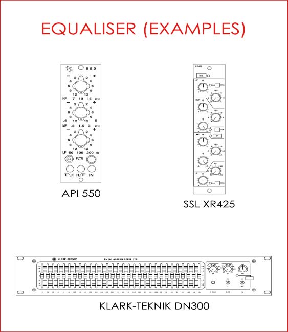
EQUALISERS
Equalisation may be described as frequency (band) specific level control and it is commonly used to alter the timbre of audio signals or the response of sound reproduction systems. Equalisers are frequently utilised to repair or enhance recorded material, improving tone and clarity (balance), and are also used creatively to personalise music productions. The following is an overview of equaliser types and their applications.
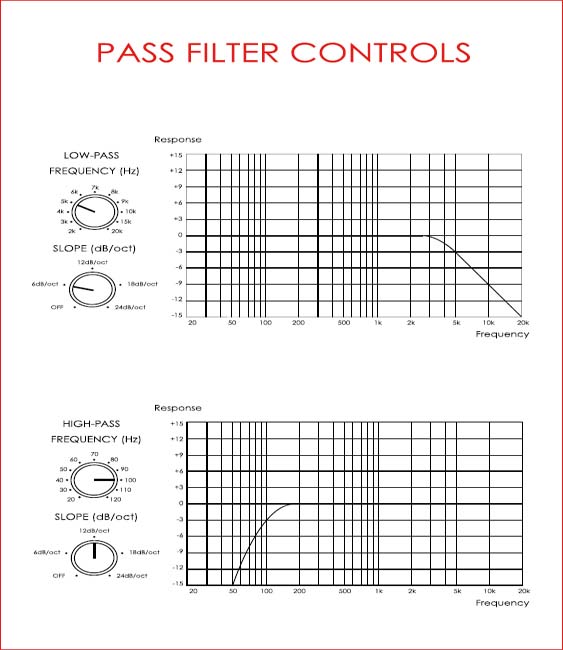
Filters
Filters are primarily used for the removal of unwanted signal content, e.g. rumble, hiss, etc., providing an increasing level of attenuation above or below a given frequency. The rate of this attenuation is given in decibels per octave (filter slope) and it commonly varies between devices. Low and high pass filters may present no variable controls, i.e. incorporating fixed cut-off frequency and slope, or may offer selection facilities over:
• Frequency
• Slope (mostly found in digital units, whereas analogue filters commonly present fixed slopes).
Filter Slope
Filter slopes hold a direct proportionality with the number of reactive components (poles) used in EQ design:
• 1st Order / 1-Pole Filters: 6 dB per octave roll-off
• 2nd Order / 2-Pole Filters: 12 dB per octave roll-off
• 3rd Order / 3-Pole Filters: 18 dB per octave roll-off
• 4th Order / 4-Pole Filters: 24 dB per octave roll-off.
From the list above it is easy to infer that in filter design, the number of poles (or the filter order) multiplied by six equals the slope of attenuation in decibels per octave.
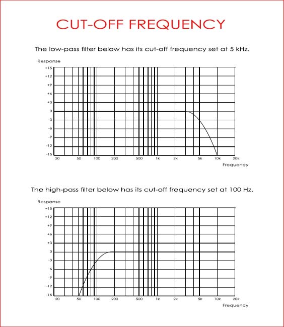
Filter Cut-Off Frequency
The ‘cut-off’ value specifies the frequency that will be attenuated by 3 dB when a filter is made active. This convention originates from basic crossovers, where such frequency represents the ‘split’ between the low and the high-ends of the spectrum (sent to the ‘woofer’ and the ‘tweeter’ simultaneously at an attenuated level).
Pass-Filters and ‘Rumble’
High-pass filters are generally used to remove ‘rumble’ from signals. These undesirable low-frequency sounds may originate from air-conditioning units, traffic, vibration from microphone stands, etc.
Mixing console high-pass filters commonly present cut-off frequencies between 85 and 150 Hz and when employed incorrectly may lead to the removal of important musical content from instruments such as bass guitar, bass drum, bass tuba, piano, etc. The use of pass filters should in such cases be avoided or approached with caution.
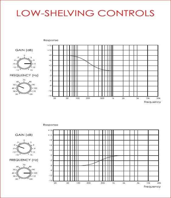
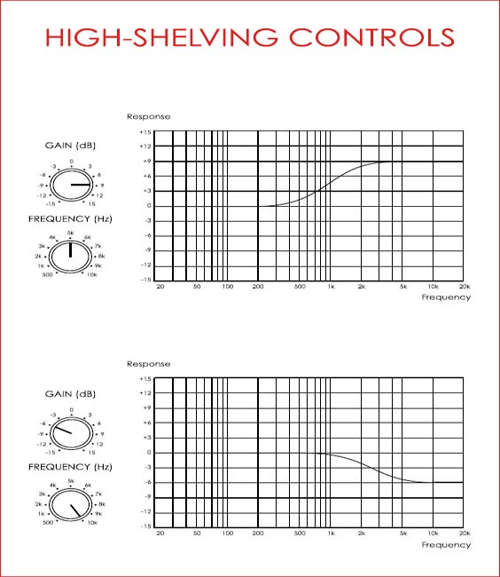
Shelving Equalisers
Shelving equalisers allow for (practical) constant attenuation or boost above (high-shelving) or below (low-shelving) a given frequency. Shelving EQ labelling methods vary considerably between manufacturers, although it seems sensible to adopt the ‘stop frequency’ as the nominal frequency of a given device (as AMS Neve and other manufacturers do), i.e. the frequency where boost or attenuation has reached a maximum ‘stable’ level.
Budget shelving units offer simple control over gain, commonly labelled as ‘bass’ or ‘treble’, while professional devices offer selection over frequency and gain.
Shelving EQ and Pass Filters
Shelving equalisers should be used with great caution and ideally employed alongside pass filters. As an example, it is vital to remove rumble before using a low-shelving equaliser to boost low frequencies.
Shelving EQ Emphasis and De-Emphasis
Shelving equalisers were (and still are) widely used in analogue tape-based recording sessions. Due to the noise floor of the medium, it is common for engineers to boost or emphasize the high-end of the material during the recording stage, reversing the process (attenuating the high-end) during mixdown. The ‘de-emphasis’ applied during mixing returns the audio content to its original timbre while reducing the audibility of tape hiss.
Peaking / Peak Equalisers
Peak equalisers, sometimes also referred to as ‘bell’ equalisers, are usually found affecting the mid-range band of ‘budget’ or semi-professional consoles. This type of EQ offers variable control over gain, but no frequency or bandwidth selection facilities.
Bandwidth
The value known as bandwidth describes the main area of effect (or the ‘focus’) of an equaliser. This value may be given in octaves or it may be presented as a single number known as Q or ‘quality factor’ (described in more detail later in this book). The bandwidth of a ‘peak’ equaliser lies between the two points found at three decibels above maximum attenuation or below maximum boost.
Digital devices, including plug-ins may offer extremely narrow Q factors or bandwidths, which may not be reached by analogue hardware devices. This allows for the very precise removal of small bands of offending frequencies from signals.
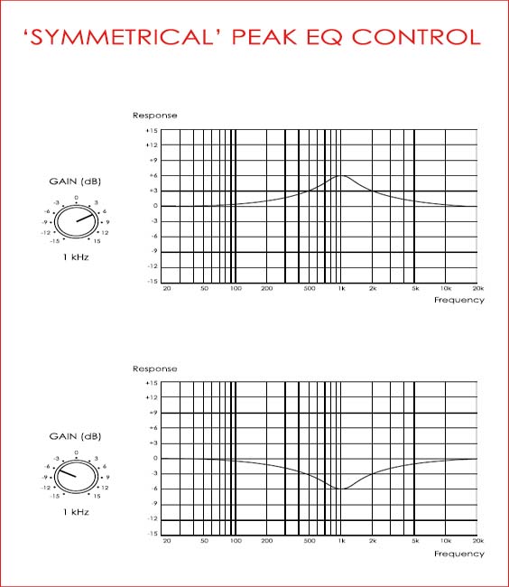
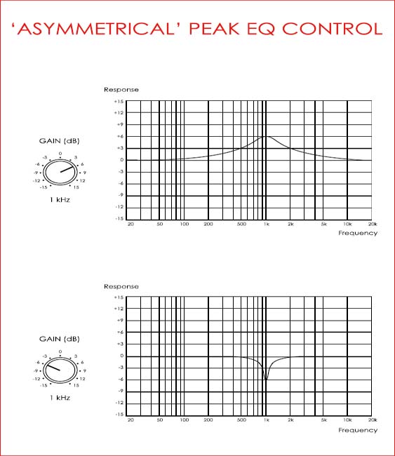
Symmetrical and Non-Symmetrical Equalisers
Symmetrical equalisers present identically shaped curves for cuts and boosts of equal absolute values, e.g. + 6 and – 6 dB. Non-symmetrical equalisers tend to offer wider boosts and narrower cuts, as the latter are frequently used for focused or ‘surgical’ repairs while boosts are approached more broadly (see pages 62 and 63).
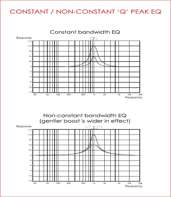
Constant and Non-Constant Bandwidth Equalisers
Some EQ units present a constant quality factor that is independent of gain, while others offer a non-constant ‘Q’, which changes according to the depth of boost or cut, i.e. the greater the equaliser gain applied the narrower the range of the effect. As examples, SSL ‘E’ series equalisers present constant Q and are favoured for precise boosts or cuts, while the same company’s ‘G’ series EQ is considered to be less surgical or more ‘musical’ by some, as it offers a non-constant, gain-dependant bandwidth (see page 64).
Graphic Equalisers
Graphic equalisers are effectively a series of ‘peak’ EQ units that control overlapping bands, arranged under a user-friendly physical layout. High-end graphic equalisers commonly offer a minimum of 31 bands, spaced at a third of an octave intervals.
Users should avoid the boosting and cutting of adjacent bands of graphic EQ, as this may defeat the purpose of the processing and introduce phase-related problems.
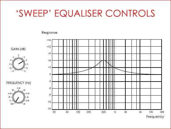
‘Sweep’ Equalisers
Also commonly referred to as ‘bell’ equalisers, sweep EQ units are similar to ‘peak’ devices, while offering added control over frequency selection. NB ‘sweep’ equalisers do not offer control over bandwidth.
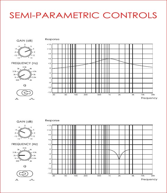
Semi and Fully-Parametric Equalisers
Parametric equalisers allow for user selection of frequency, gain and bandwidth or Q. If the control over Q is continuous, devices are said to be of fully parametric design, while if the same control is non-continuous or stepped, they are labelled as semi-parametric.
The Q Factor
The Q (quality) factor is used to describe the area of action of an equaliser. In a somewhat counter-intuitive fashion, the higher the value of Q the narrower the effect of a device, i.e. the more precise or ‘surgical’ the equalisation.
Narrow Qs are commonly used to remove small, specific portions of a signal, e.g. the unsympathetic resonance of a snare drum, without affecting the rest of the sound of the instrument.
The following are approximate values for Q that are worth remembering:
Q = 0.67 (two octaves)
Q = 1.41 (one octave)
Q = 2.87 (1/2 octave)
Q = 4.31 (1/3 octave)
Q = 17 (one semitone)
It may be helpful to consider the Q value of 1.41 (a bandwidth of one octave), as the point that separates ‘narrow’ and ‘wide’ EQ effects, i.e. equalisation will be focused if Q ≥ 1.41, while it will be broader when Q ≤ 1.41.
Paragraphic Equalisers
Paragraphic equalisers may be described as graphic equalisers that offer added control over bandwidth (alongside gain).


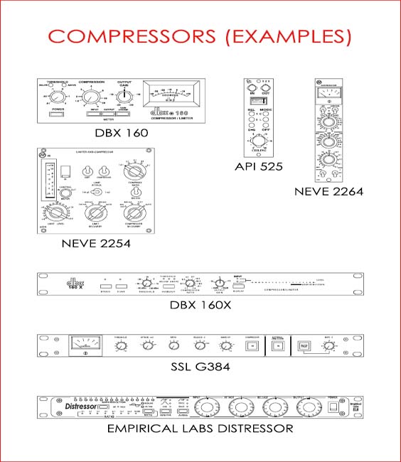
DYNAMIC RANGE PROCESSORS
Dynamic range processors may be broadly described as gain riding devices, providing automatic control over the level of signals. This control may be effectively used to reduce (compressors and limiters) or extend (expanders and gates) the dynamic range of audio material.
Compressors / Limiters
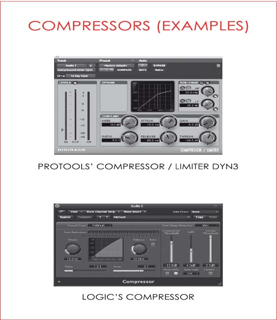
Compressors / limiters are used to reduce the dynamic range of signals and may incorporate all or some of the following user-adjustable parameters:
• Threshold – The level at which a compressor will initiate gain reduction, i.e. the level at which signals will start being affected by a compressor (possibly influenced by a ‘knee’ function).
• Ratio – A gain reduction ‘intensity’ control (x:1), this parameter determines the proportion between input and output levels above the threshold (overshoot).
• Attack – A time-related function determining the speed at which a compressor will reach its user-defined ratio of gain reduction (x:1) once input signals rise in level above the threshold. The primary function of the attack parameter is to determine the speed at which a compressor will start working once signals overshoot the threshold (although attack still applies for further increases in level above the threshold).
• Release – A second time-related function determining the speed at which a compressor will diminish its gain reduction when input signals fall in level from previous readings above the threshold. The primary function of the release parameter is to determine the speed at which a compressor will stop affecting signals once their level drops below the threshold (although release will also affect decaying signals above the threshold).
• Knee – This parameter may be described as a fine-tune control over threshold and attack, i.e. a soft knee function effectively lowers the threshold and slows down the attack of a compressor.
• Make-up gain – A post-signal processing level control commonly found at the output stage of compressors.
• Input level – On devices with no time constant controls, i.e. no attack or release, this function dictates the extent of compression by raising or lowering the level of input signals above or below a fixed threshold.
• Output level – On devices with no time constant controls, this function dictates the overall output level.
Although the gain-reduction cell corresponds to a portion of a larger, complex system, compressors are usually described according to their gain stage, falling (mostly) within the following categories (see page 78):
• Delta-Mu (Vari-Mu)
• Opto-Electrical
• FET
• VCA
Compressors and Microphone Technique
Skilled singers use microphone techniques to help avoid the need of compression during recording. Such techniques may be as simple as changing distances to the microphone dynamically or accompanying short bursts of high-impact vocal delivery with body movements that make the performer ‘look away’ from the microphone, e.g. the raising of arms, a slight spinal bend backwards, etc.
Fader Riding and Compression
Manual compression was used extensively in the heyday of analogue tape recording, where due to the limited dynamic range of the medium, engineers were commonly required to ‘ride faders’ to tape. As an example, it was usual for classical music recordists to follow the score slightly ahead of the performers in order to prepare themselves for fortissimo sections that would require faders to be brought down in level (in order to avoid ‘clipping’). The aforementioned process was generally followed by a mixing stage were manual expansion would return the audio program to its original dynamic range.
Compressors may be thought of as an automated replacement to be used when human reaction times would be too slow for appropriate fader riding.
Page 75 depicts a comparison between the effects of compression and those of fader riding.

Peak / RMS Detection
Compressors may react according to the peak or the RMS of input signals. Level detection circuits based on peaks present a faster response and are usually more efficient in the control of extreme transients (limiting). RMS-based dynamic processors work on a level average and tend to be gentler in effect, although they may be unsuitable for percussive material.
‘Look-Ahead’ Detection
‘Look-ahead’ circuitry is commonly used when instantaneous gain reduction is needed, e.g. for device protection, broadcast limiting, etc. Compresssors and limiters that offer a ‘look-ahead’ function, delay the signal in their main audio path so level detection may take place and gain reduction initiated before signals overshoot the threshold.
Limiters
Limiters may be broadly described as compressors with very high ratios and fast attack (and ideally with a look-ahead function). These are commonly used to maximise the loudness of audio material, to protect equipment and for broadcasting purposes.
The Side-Chain
Compressors incorporate two audio paths, which are commonly fed with the same input signal. The function of the first one, the side-chain, is that of level detection, i.e. this is where the amplitude of the program material is determined and the audio signal (AC) is converted onto a control voltage (DC). The second and main path is where signal processing (compression) takes place.
A compressor’s side-chain may be fed with a signal that differs from the one that will be processed in conditions where the desired gain reduction may not be achieved easily. This could be the case when the amplitude of the portion of the signal to be compressed is not sufficiently greater than the material’s average or when gain reduction is triggered by components that should not be attenuated, e.g. the low-end.
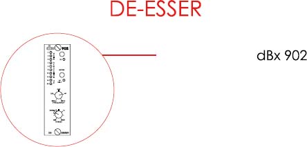
De-Essing
De-essing is a common alternative when sibilance (high amplitude consonants such as ‘s’, ‘t’, etc.) cannot be controlled through the use of pop shields. A de-esser is essentially a compressor with an equalised side-chain input.
In de-essing, a main vocal signal is fed to a compressor’s input and an exaggeratedly sibilant (equalised) version of the same vocal is fed to the device’s side-chain. The latter ensures gain reduction only takes place, or it is maximum, at points when sibilance is detected.
A process similar to de-essing may be used to reduce fretboard and finger ‘squeaking’ sounds from acoustic and electric guitar recordings.


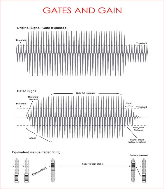
Expanders / Gates
Expanders / gates are used to increase the dynamic range of signals and may incorporate all or some of the following user-adjustable parameters:
• Threshold – The level at which an expander / gate will stop gain reduction, i.e. the level at which a gate will ‘open’.
• Ratio – A gain reduction ‘intensity’ control (x:1), this multiplier determines the proportion between input signal undershoot (the portion of the signal below the threshold or below threshold minus hysteresis) and effective output level.
• Attack – A time-related function determining the speed at which an expander / gate will stop gain reduction completely (gate fully open).
• Hold – The length of time in which an expander / gate will remain inactive, i.e. delay its gain reduction, once signals undershoot the threshold (or threshold minus hysteresis).
• Release – A second time-related function determining the speed at which an expander / gate will realise its full ratio or range of gain reduction (gate fully closed).
• Range – The maximum level of gain reduction applied to gated signals.
• Hysteresis – A decibel value describing the difference between the threshold (the point at which the gate will open) and the point at which a gate will start attenuating signals (gate closing).
Gating and Expansion
Expansion implies variable gain reduction that is proportional to a ratio, while gating entails a fixed, predetermined level of attenuation, i.e. a given amount of decibels, taken from signals that do not overshoot a set threshold.
The following is an illustration comparing the effects of gating with those of fader riding.
Expanding Signals
Expansion is commonly used to reduce the level of decaying signals, e.g. expansion may help to reduce the audibility of amplifier noise, as an electric guitar’s signal falls back to very low levels (approaching the level of idle amplifier ‘hum’).
Duckers
Duckers are commonly used in broadcasting when a main signal, e.g. a voice-over, controls (expands / attenuates) the level of another unrelated one, e.g. background music.
Key input
In a similar fashion to side-chained compression, key input gating allows for the dynamic range of a signal to be controlled by the level of another, possibly unrelated one. As an example, a drum ‘room’ microphone may be gated with a snare drum signal as a key input, so that only when the snare is struck, the sound of the room microphone will be audible.


MIXING CONSOLES
Audio consoles vary greatly in design and features while sharing the same basic functions, commonly working as:
• Central routing devices – Allowing for signals to be routed between different (own) internal and external points with minimal need for patching, e.g. from microphone input to multitrack send.
• Signal processing and amplification devices – Offering facilities for level matching and signal manipulation, e.g. equalisation.
• Signal summing devices – Making it possible for multiple signals to be summed or combined.
Console Types
Mixing consoles may be classified according to design, falling into one of the following categories:
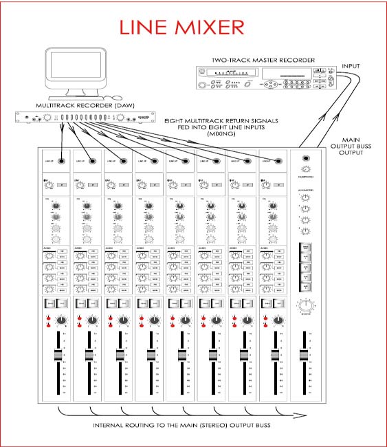
• Line mixer – A very basic device with a single set of I/O (input / output) module faders and no microphone preamps. Line mixers are commonly used for the summing of line level signals, e.g. the back end of DAW-based mixing systems.
• Split console – A mixer that accepts line and microphone level signals, while still offering a single set of I/O module faders. These are commonly operated with half the number of channels sending signals to the multitrack recorder, while the other half is used for monitoring (multitrack returns).
• Semi in-line console – A console that accepts line and microphone level signals and offers two sets of faders per module, corresponding to the two different signal paths (channel and monitor or Mix B). Semi-in line consoles commonly present a ‘tape input’ that may be routed to monitor or Mix B paths (record) or to channel paths (mixdown).
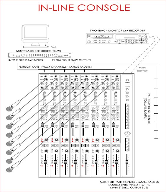
• In-line console – Similar to a semi in-line console, although a true in-line mixer has the output of its corresponding multitrack machine feeding both (channel and monitor) paths simultaneously. The use of a patchbay is usually required for the operation of this type of console.
• Matrix console – Commonly used for live sound stage monitor mixing, matrix consoles may offer a considerable number of auxiliary busses, but no linear channel faders (not commonly used for recording purposes).
The illustrations that follow depict basic set-ups incorporating the different types of mixing consoles described in this section.

Console Elements
Mixing consoles may be very broadly depicted as a collection of channels and busses interconnected via routing with flexible monitoring capabilities. Channels commonly carry signals originating from individual sound sources, e.g. a microphone, while busses are summing points where multiple signals are combined. This allows for numerous sound sources to feed a single input device, e.g. two bass drum microphones routed to the same track, guitar and snare drum signals sent to the same reverb unit, multiple signals summed and sent to a headphone amplifier, etc. It is important to note that the monitor or Mix B paths of in-line consoles may be simply described and treated as alternative channels that carry line level signals that commonly originate from recording devices. This may be easier to understand when one works with a digital console, where signals ‘going to’ and ‘returning from’ the recorder are usually assigned to channels on different layers, e.g. Channels 1 – 24 for ‘send’ and Channels 25 – 48 for ‘return’. In the case of analogue consoles, these two ‘layers’ translate as two faders (or a fader and a rotary potentiometer) on the same I/O module.
The following sections contain a brief description of common mixing console elements and their functions. It is important to note that some digital mixers may offer extra facilities such as analogue-to-digital and / or digital to analogue conversion, internal effects processing, etc.
Input / Output (I/O) Modules or Channel Strips
Common I/O modules or channel strips incorporate the following sections:
1. Input Section
The input section of a module corresponds to the entry point to its channel path. This section may include the following controls:
• ‘Mic’ gain – Microphone preamplifier level control
• Line trim – Line amplifier level control
• Input flip – Channel input selection (microphone or line)
• Sub-Group – This switch assigns the signal from a group buss to its corresponding channel path, e.g. group buss 1 will feed channel 1, etc.
• 48 V – Phantom power
• Pad – Fixed microphone input level attenuation (– 20 to – 30 dB)
• Polarity (also referred to as ‘phase’) – Used to invert the polarity of signals
• High-pass filter – Commonly with fixed cut-off frequency if placed here.
Shared Microphone / Line Input Preamplifiers
Budget consoles commonly offer a single gain control for both microphone and line inputs. In such cases, line level signals are attenuated (internally) through a resistor network, before reaching the preamplifier.
2. Auxiliary Section
The auxiliary section of the I/O module provides access to the auxiliary busses commonly used for effects sends, headphone mixes, etc. This section may contain some or all of the following controls:
• Source selection, e.g. large or small fader / channel or monitor (Mix B) path
• Pre or post-fader sourcing selection
• Send to auxiliary on/off
• Auxiliary send level controls (each corresponding to a given mono or stereo buss)
• Auxiliaries pairing switch (which may turn a level control into ‘pan’).
Pre / Post Auxiliary Sourcing
‘Cue’ mix signals are normally sourced pre-fader and pre-cut, so engineers may change the balance and content of their control room (monitor) mix without affecting the musicians’ headphone levels. This includes the ‘sends’ and ‘returns’ to and from processing units, if these are used to add effects to the ‘cue’ mix, e.g. reverb added to a singer’s headphone signal.
In mixdown, ‘auxiliaries’ used for effects sends are commonly sourced post-fader and post-cut, where the ‘muting’ or ‘cutting’ of a ‘dry’ signal (instrument) will be followed by a corresponding ‘mute’ or ‘cut’ of its effects returns or ‘wet’ version.
Auxiliary Busses Feed to Group Busses / ‘EFX’
Some consoles allow for the routing of auxiliary buss outputs to the group busses. This facility may be explored for the creation of multichannel or ‘surround’ mixes, as long as each group buss is fed to a corresponding amp/speaker. In such case, the I/O module ‘aux’ level pots control the amount of channel ‘send’ to the different console outputs, e.g. channel to Aux 1 to Group 1 to left front speaker. Consoles with stereo auxiliary busses may also offer a panning function facilitating the routing of signals between speakers.
The same facility may alternatively be employed for the real-time use of computer effects through traditional ‘aux send’ means, in setups where the DAW is fed via group busses.
3. Insert Section
Inserts are commonly used as a means to access outboard equipment for the serial processing of signals that can be improved or enhanced, e.g. inserts may be used to equalise vocals that lack ‘sparkle’ or ‘air’, where the original ‘dull’ microphone sound is enhanced before it is recorded.
Insert sections should ideally offer:
• Channel or monitor path (Mix B) assignment selection
• Pre or post-EQ placement option
• An ‘insert in’ or ‘bypass’ function, allowing operators to compare the original and the processed versions of a signal.
4. EQ Section
Professional mixing consoles frequently incorporate multi-band equalisers and cut filters in their I/O modules. The type of equalisation offered may vary according to frequency band, where shelving or sweep components are commonly used at the two ends of the spectrum (low and high bands) and semi or fully-parametric ones manipulate the mid-range bands (low and high-mid). EQ sections should ideally offer channel or monitor path assignment selection and a ‘bypass’ function, allowing operators to quickly A/B the original and the equalised versions of signals.
5. Dynamics Processing Section
High-end mixing desks may feature I/O module and output buss compressors, limiters, expanders, gates and duckers. In the case of in-line consoles, access to the dynamics section may be assigned to channel or to monitor (Mix B) paths.
The dynamics processors found in I/O modules may offer:
• Assignment selection (channel or monitor path)
• Placement options (pre or post-EQ)
• Side-chain or key input access
• A ‘dynamics on/off’ or a ‘bypass’ switch.
6. Fader Section(s)
The large fader section of a module is allocated to the channel path, while the small one is assigned to the monitor or Mix B path. This always holds true, regardless of global operation status (Record or Mix), unless a console is capable of operating in ‘fader reverse’. Fader sections commonly contain:
• A large or a small fader
• A solo switch
• A mute switch.
Destructive / Non-Destructive Solos
Professional consoles offer two types of solo facilities, namely destructive (or in-place) and non-destructive (split into AFL and PFL).
1. Destructive (In-Place) Solos
When a destructive solo is performed on a path, all other similar (or all other) paths are cut / muted, i.e. only the ‘soloed’ path will have its routing preserved. Destructive solos are commonly used in mixdown sessions when engineers aim to showcase a single channel or element, which will feed the main output stereo buss in isolation, e.g. a lead vocal acapella section, a rhythm guitar break, etc.
2. Non-Destructive Solos
When a non-destructive solo is performed, a copy of the signal in the soloed path is routed to a dedicated solo buss, which is automatically sourced at the control room monitoring section. All other paths and their routings are not affected. Non-destructive solos are commonly used in recording sessions, allowing for the monitoring of signals at different stages of the chain. This feature can be particularly helpful for troubleshooting.
There are two common types of non-destructive solos:
AFL / After Fader Listen – The solo buss feed is post-fader.
PFL / Pre Fader Listen – The solo buss feed is pre-fader.
Solo in Front
Some consoles offer a solo in front feature. A solo in front is essentially a variation of an AFL non-destructive solo, allowing for the monitoring of all ‘non-soloed’ paths as a ‘background’ (at lower level in relation to the main soloed path). The amount of dimming applied to the ‘non-soloed’ paths is given in percentage form, e.g. 50 percent implies that the non-soloed paths will be monitored at half the level of the soloed path.
Solo Safe / Solo Isolate
A path may be set onto ‘solo isolate’ or ‘solo safe’ mode. This implies that such path will not perform solos destructively and, more importantly, that such path will not be cut in the case of a destructive solo, e.g. this feature is commonly used to ensure that channels fed by effects processor returns will not be muted if their counterpart effects processor send paths are soloed during mixdown.
7. The Routing Matrix
Routing matrices offer access to group and / or main output busses. Some professional consoles contain two matrices in each module, while others may only incorporate a single one, commonly placed within or near the large fader section.
The use of routing matrices varies according to console status. In ‘Record’, status group busses are commonly used to feed the multitrack recorder, while in ‘Mix’, group busses are frequently used as a means to access outboard processing equipment (working as ‘extra aux busses’). Routing matrix sections usually incorporate a pan pot for odd/even assignment.
Pan Assign
Pan pots are used in conjunction with routing switches to address signals to multiple destinations. As an example, engineers choosing to record multi-microphone drum set-ups to two tracks of a multitrack recorder (stereo) may assign the output of the different channels to two (odd/even) group busses, choosing to pan left or right in order to establish a stereo image during playback.
Example – Recording Drums in Stereo (Drummer’s Perspective):
• Bass drum – Routed to groups 1 and 2 (panned centre)
• Snare drum – Routed to groups 1 and 2 (panned to 11:00)
• Hi-hat – Routed to groups 1 and 2 (panned to 10:00)
• OH left (hi-hat) – Routed to groups 1 and 2 (panned hard-left)
• OH right (floor tom) – Routed to groups 1 and 2 (panned hard-right).
Pan vs. Balance
Pan and balance pots precede routing decisions. The first allows for a single, mono source to be routed to pairs of destinations at different levels, e.g. when a mono signal is routed to the left and the right side of a Mix or Output Buss, etc., while the second allows for the control over the level of the two ‘sides’ of stereo signals, when routed to stereo destinations.
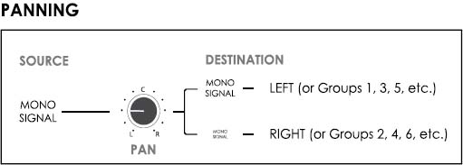
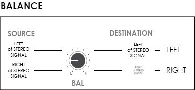
• It is common for consoles to incorporate pan pots in mono channels and balance pots in stereo channels.
• Balance control pots are commonly found in hi-fi amplifiers.
Direct Outputs
Some consoles offer direct output facilities, which allow individual signals to be routed to ‘multitrack sends’ directly, i.e. without going through group busses. Sophisticated professional consoles allow operators to choose where the ‘direct’ signal is sourced from, e.g. channel path pre-fader and pre-processing (EQ and dynamics), channel path pre-fader, but post-dynamics or channel path post-fader.
A few mixing desks allow for the routing of monitor path signals to ‘multitrack send’. This may be used for bouncing tracks or for maximising the recording capabilities of smaller consoles. It is very important to note that feedback loops may occur easily between the monitor paths and the recorder, e.g. if the ‘direct’ function is sourcing the ‘multitrack send’ (off-buss) signal from the monitor path.
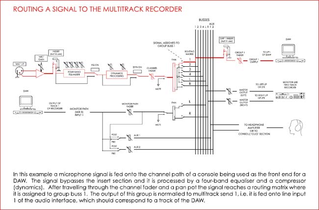
The following is an illustration depicting ‘direct’ and group buss multitrack assigning:

The Master Section
The master section of audio consoles commonly incorporates all or some of the following elements:
1. Master Group Section
This section may offer linear faders controlling the level of group busses. A small routing matrix and a pan pot may also be incorporated, allowing for the output of group busses to be routed to the main stereo output buss. Some mixers also offer access to the auxiliaries from the group busses and this facility may be explored for the creation of streamlined ‘cue’ mixes based on instrumental groups, e.g. drum groups, guitar group, etc.
2. Master Stereo (Mix / Output) Buss Section
A linear fader is frequently used to control the main stereo output buss level. In some cases, two separate faders are found controlling the individual level of the left and right channels of the stereo buss. The master output buss section may also contain a ‘mute’ button.
3. Auxiliary Master Section
This section contains the master controls over the auxiliary busses, commonly including:
• Auxiliary buss master on/off switch
• Auxiliary buss master level
• Auxiliary buss master EQ (commonly shelving or cut-filters)
• Auxiliary pairing switch.
4. Effects (Echo / Rev) Returns Master Section
This section contains the master controls over the ‘effects’ or auxiliary returns and it may include:
• Effects returns master level control
• Effects returns master on/off switch
• Effects returns master EQ (commonly shelving or pass-filters)
• Routing matrix – Allowing for the assigning of effects to the main output buss and/or the headphone mixes.
5. Tone Generator / Oscillator Section
This section provides tone generating facilities, allowing for equipment testing, alignment and troubleshooting.
6. Meters
The master or central area of consoles may incorporate output, group and auxiliary buss meters alongside control room (two-track) metering facilities. The meter section may also include a global I/O module metering selection matrix.
7. Control Room Monitoring Section
The control room monitoring section may include:
• Monitoring level control – Main level to amplifier or active speakers
• Mono function – Left and right output buss combining function (used for checking polarity coherence)
• Dim – A monitor level attenuation switch
• Monitoring source matrix – Selection of control room monitoring sources, including the Mix Buss, auxiliary busses, ‘cue’ mixes and external inputs
• Speaker selection.
8. Communications Section
This section offers control over the communication between the control room and the studio (live room). Commonly referred to as the ‘Talkback’ section, this area may include:
• A built in microphone
• Level control
• Talkback and return talkback on/off switch
• Talkback and return talkback level controls.
Console Signal Flow (Block) Diagrams
The path that connects a transducer to the recording device may vary in size and, consequently, in number of gain stages. It is extremely important for technicians to have an understanding of signal flow, as without such knowledge it would be difficult, if not impossible, to optimise signals before committing them to the storage medium. Audio chains can be as basic as a single microphone connected to a computer interface with a built-in preamplifier or as complex as what is found in commercial multitrack studios built around large format consoles. In all cases, recordists must consider the variables that may affect sound quality and ensure that the path to the recorder is as short as possible and free of unreasonable gain changes in order to maximise the signal-to-noise ratio.
Home studio recordists who work with single sound sources in isolation commonly have little to worry about regarding signal flow, i.e. their signal paths are short, with one gain stage corresponding to the audio interface’s ‘mic’ preamplifier. The picture is considerably different when engineers choose to record entire groups simultaneously using a mixing console and outboard processing. In such cases, the use of block diagrams may be essential as such documentation frequently provides technicians with a clear and linear overview of signal flow from console input to multitrack recorder to two-track recorder to loudspeakers, etc.
Signal flow diagrams come in different shapes and sizes, utilising a variety of symbols that may change according to manufacturer. However, a few universal rules seem to apply and are observed in the majority of documents, such as:
• Signals flow from the left to the right of a page.
• Routing destinations are depicted as vertical lines.
The following pages present an overview of block diagrams:


PATCHBAYS
Patchbays allow for the easy interconnection between the various devices found in a music production set-up. The flexibility they provide may help increase the efficiency of the recording process significantly, where the sometimes demanding and time-consuming equipment patching procedure is avoided or simplified.
Patchbays vary in kind (as audio connectors) and in size, spanning from models with a few domestic ‘jack’ patch points to large ‘B-gauge’ or bantam professional models. The following are some connectivity options found in patchbays used alongside in-line consoles:
• Microphone lines – Where the ‘live room’ microphone cables terminate, N.B. the term may appear confusing, as ‘lines’ is used here in place of ‘leads’ or ‘cables’ (not implying line level).
• Microphone inputs – Access point to the microphone level channel input of the console.
• Multitrack returns – Where the cables originating from the multitrack recorder output terminate.
• Channel line inputs – Access point to the line level channel inputs of the console.
• (‘Off-tape’) monitor input – Access point to the monitor path.
• Channel insert sends – Where signals may be sourced from for serial processing, e.g. dynamics.
• Channel insert returns – Access to a point where signals may be replaced with a processed version, e.g. equalised, compressed, etc.
• Group outputs – Where group buss signals may be sourced from, e.g. for the feeding of effects processors in mixdown.
• Multitrack sends / Off-buss monitor path input – Access point to the multitrack recorder inputs and to monitor paths (with a ‘send’ signal).
• Auxiliary or effects sends – Where signals may be sourced from for parallel processing, e.g. reverb, delay, etc.
• Auxiliary or effects returns – Access to especial console inputs, commonly fed by the output of effects processing units.
• Main outputs – Where the main stereo (mix) buss signal may be sourced from.
• Two-track input – Access to the two-track master mixdown recorder.
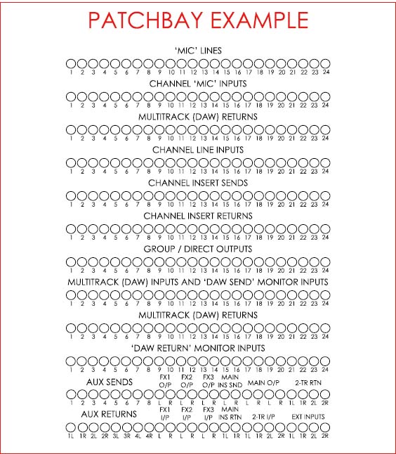
The following illustration is an example of a patchbay wired for a studio containing:
• An in-line console offering:
- Twenty-four I/O modules
- Eight mono auxiliary busses
- Four stereo auxiliary returns
- One main stereo output buss
- Two ‘external’ stereo control room monitoring inputs
• Three external effects processors
• One two-track recorder (for the recording of mixes)
• A DAW used as a multitrack recorder.
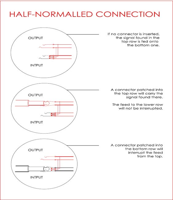
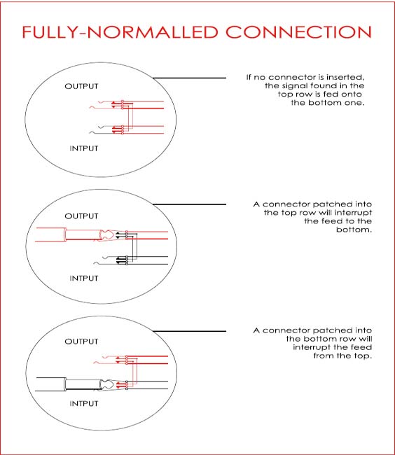
Patchbay Normalling
In the previous patchbay example, the following rows would commonly be ‘normalled’:
‘Mic’ Lines – ‘Mic’ Inputs
A fully-normalled connection allowing operators to reroute microphone signals originating from a live room (‘mic’ lines) to non-corresponding channel ‘mic’ inputs, e.g. the signal from the microphone connected into the first patch point in the live room wall box (‘mic’ line 1) can be rerouted (‘cross-patched’) onto Channel 25 (as opposed to the default Channel 1). This facility is useful when a console has a non-functional I/O module or ‘mic’ preamplifier or when the wall box in the live room has a bad connection. Full-normalling is used here to avoid the splitting of a microphone signal between two channels and/or the connection of two microphones and one ‘mic’ preamplifier in a circuit.
Multitrack Returns – Channel Line Inputs
A half-normalled connection found in true in-line consoles allowing operators to use a copy of the multitrack return signal without breaking the feed to the channel path’s line input. A patching into the ‘Channel Line Input’ row will otherwise break the aforementioned normalling, i.e. the patched signal will replace the multitrack return signal feeding the channel path’s line input by default.
Channel Insert Sends – Channel Insert Returns
A common half-normalled connection where operators can use a copy of the insert send signal, e.g. for parallel processing, while the patching into insert return will replace the signal in the original path.
Group / Direct Outputs – MTK Sends / ‘MTK Send’ Monitor Inputs A half-normalled connection found in true in-line consoles where the group buss or the ‘direct’ output’ signal (‘multitrack send’ signal) can be fed onto the monitor path. A patching into the upper row will provide operators with a copy of the group buss or the ‘direct out’ signal, which may be used for a variety of purposes such as cross-patching to a non-corresponding track, e.g. Group 1 feeding Track 2, or the routing of group signals to effects processors during mixdown (commonly used when all auxiliary busses are already in use).
Multitrack (DAW) Returns – ‘MTK Return’ Monitor Inputs
Another half-normalled connection found in true in-line consoles where the multitrack recorder also feeds the monitor path via its own dedicated input. A patching into the upper row will provide operators with a copy of the multitrack return signal, while the patching into the lower row will force a signal onto the monitor path’s default input.
Main Output – Two Track Input
A half-normalled connection feeding the main output buss signal to the two-track recorder. The patching onto the upper row provides users with a copy of the buss signal while the patching into the lower row replaces the signal feeding the two-track recorder.
Two-Track Return – External Input
A half-normalled connection allowing for the audition or confidence monitoring of the two-track recording in the control room. Again the upper row provides a copy of a signal (in this case the two-track recorder return) while the bottom row represents a break in the normalling allowing for the quick routing of signals to the control room monitoring section (useful for the playing of devices such as mp3 players, etc.)
The following pages describe the process of patchbay normalling graphically.
EFFECTS PROCESSORS
A number of effects processing devices are utilised in recording and mixing sessions. These may be grouped according to their principles of operation and split into the following categories:
• Time-Delay-Based Effects
• Amplitude-Based Effects
• Filter-Based Effects
• Waveform Distortion Effects
• Other Effects.
The following sections describe common effects processors used in music production.
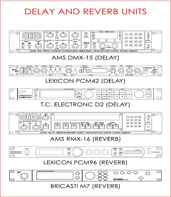
Time-Delay-Based Effects
Reverberation
Artificial reverberation devices are commonly used to add depth or dimension to signals. Some digital reverb presets are designed to simulate physical spaces, e.g. halls, chambers, rooms, etc., while others are emulations of electro-mechanical devices, e.g. spring and plate reverbs. It is common for reverb units to offer the following user-changeable parameters:
• Size or decay – The overall dimensions of the space or of the electro-mechanical device being simulated, i.e. the length of reverberation.
• Pre-delay – The time separating the ‘dry’ or direct sound from its first early reflection.
• (HF) Damping – A level attenuator affecting the high-frequency content of a reverberation effect.
• (LF) Damping – Similar to HF damping, LF damping allows for the control over the level of low-frequency content.
• Crossover – The point where the spectrum is divided into high and low frequencies, this parameter affects high and low-frequency damping.
• Density – The spacing between echoes and, therefore, the total number of reflections that fill up the reverberation decay time.
• Diffusion – The overall geometry of the reflection cluster, i.e. how unevenly the spacing between reflections develops over time.
• Mix – The relationship (ratio in percentage) between ‘wet’ and ‘dry’ sounds.
Practical Use of Reverberation Parameters
• Pre-delay – Longer pre-delays are employed to simulate environments with widely spaced boundaries (walls) and may help improve the clarity of focal elements, e.g. main vocals, solo electric guitar, etc.
• (HF) Damping – ‘Darker’ sounding artificial reverberation is generally perceived as more realistic.
• (LF) Damping – The attenuation of low-frequency content commonly helps clear ‘muddy’ or ‘cluttered’ reverberant sounds.
• Density – Dense reverberation is usually more suitable for percussive sources, e.g. drums (less individual sounding echoes), while sparse effects may suit vocals and other less transient sounds.
• Diffusion – Diffusion plays a very important role with longer decay presets, making the latter less artificial sounding.
NB Diffusion and density changes are easier to perceive when percussive sound sources are used.
Echo / Delay
Although similar to reverberation, echo or delay effects are commonly used in a more creative or less realistic fashion, due to the discrete or discernible nature of the reflections they produce. The following are common echo / delay parameters:
• Time or delay – The gap between echoes or copies of the ‘dry’ signal.
• Feedback – The total number of echoes. NB negative feedback implies the echoes are opposite in polarity in relation to the ‘dry’ signal.
• (HF) Damping – Same as in reverberation.
• (LF) Damping – Same as in reverberation.
• Crossover – Same as in reverberation.
• Mix – Same as in reverberation.
Modulated Delay Effects
Modulated delay units generate dynamically changing effects including ‘flanging’, ‘chorusing’, ‘vibrato’, ‘harmonising’, etc. This is commonly achieved through the use of low-frequency oscillators (LFOs) manipulating delay times. The following are basic parameters commonly found in modulated delay, flanger, chorus and vibrato devices:
• Delay – The base delay value altered by the modulation.
• Depth – The amount of delay modulation, i.e. the amplitude of the LFO wave.
• Rate or speed – The speed at which the delay time is changed, i.e. the frequency of the LFO.
• Waveform – The shape of the LFO wave, e.g. sine, square, triangle, etc.
• Resonance / Feedback / Regeneration – An internal feedback control making modulated delay effects more pronounced.
• Manual – The original centre frequency of modulation, i.e. the ‘ringing’ frequency.
Flanger and Chorus Modulated Delay Times
The following approximate modulated delay times may be used for the generation of flanger and chorus-like effects:
• Flanger – From 1 ms to 15 milliseconds (approximately)
• Chorus – From 15 ms to 30 milliseconds (approximately)
Natural Echo / Reverberation
Some commercial studios incorporate purpose-built natural reverberation chambers, containing amplifiers / loudspeakers and microphones for the production and pick-up of reverberation. Such chambers may contain different materials with variable acoustic properties, allowing for the manipulation of reverb characteristics.
Recordists on a budget may explore the use of reflective environments such as stairwells, garages, bathrooms, etc. for the purpose of adding natural reverberation to recordings. It is nevertheless important to note that small rooms may add unflattering colouration to recordings due to low-mid frequency resonances (which may clash with the key of the song performed and compromise clarity).


Amplitude-Based Effects
Tremolo
Tremolo units alter the level of signals in a cyclical manner, generally producing a ‘stutter-like’ effect. Common tremolo parameters include:
• Depth – The amount of amplitude modulation, i.e. the intensity of the effect, dictated by the level of the modulating LFO wave.
• Rate or speed – The speed at which amplitude is modulated or altered, i.e. the frequency of the LFO.
• Waveform – The shape of the LFO wave, e.g. sine, square, triangle, etc.
Ring Modulation
The principle of operation of ring modulators is similar to that of tremolo devices, although a high-frequency oscillator (or an upper range LFO) is used. Ring modulators generally produce metallic or robotic sounding results. The parameters found in ring modulators are similar to those of tremolo units.
Auto-Panning
Auto-panners move signals dynamically across the stereo field. Auto-panning device parameters include:
• Depth – The intensity of the panning effect.
• Rate or speed – The speed of panning.
• Waveform – The shape of the LFO wave, e.g. sine, square, triangle, etc.
• Width – How much of the stereo field is covered by the effect.
Filter-Based Effects
Phaser
Although sometimes described as another by-product of delay modulation, phasing is effectively achieved through the use of sweeping notch filters, as an altering of delay time would incur in pitch shifting (traditionally not a characteristic of the so-called ‘phaser’ effect).
Phasers also employ LFOs (used for the modulation of filter cut-off frequency) and present the following user-controllable parameters:
• Depth/Sweep – How far the notch filters will be swept, i.e. the amplitude of the LFO.
• Rate or speed – The speed at which the notch frequencies are swept, i.e. the frequency of the LFO.
• Waveform – The shape of the LFO wave, e.g. sine, square, triangle, etc.
• Feedback/Resonance – An internal feedback control, i.e. the output of the filters is fed back into their input.
Wah-Wah
The effect known as ‘wah-wah’ is accomplished through the use of a low-pass filter with a resonant peak. The filter’s cut-off frequency may be modulated ‘manually’, e.g. by a foot pedal, or automatically by an LFO.
‘Auto-wah’ effects processors may also utilize envelope following circuitry as a source of modulation, i.e. the cut-off frequency is made directly proportional to the amplitude of the input signal.
Vocoder
In the vocoder effect, the characteristics of one signal, e.g. vocals, are superimposed onto those of another, unrelated ‘carrier’ signal, e.g. a synthesiser.
Waveform Distortion Effects
Overdrive / Distortion / Fuzz
The original idea behind the overdrive effect was to provide a gain boost to instrument level signals, e.g. electric guitars, on the way to the amplifier. This gain boost was set so the input stage of the amp would be overdriven, resulting in distortion. Overdrive effects processors, e.g. guitar pedals, were devised to generate their own internal distortion.
Distortion and fuzz effects offer progressively more extreme manipulation of waveforms, where the source signal is clipped more radically in either a symmetrical or non-symmetrical fashion. These effects were originally devised to allow instruments to produce harmonically rich or very aggressive sounds at low(er) amplifier levels.
Other Effects
Other effects are found in use during recording / mixing sessions. These include aural exciters, Leslie cabinets, talk-boxes, pitch correction applications, etc. Some of them correspond to a combination of different manipulators into a complex effect, e.g. ‘exciters’ and Leslie, while others are unique in the way they operate.
The Use of Effects in Recording / ‘Printed’ vs ‘Monitor’ Effects
Most recordists seem comfortable employing signal processing for the creation of rough (monitor) mixes, ‘cue’ mixes and other procedures that affect multitrack return signals, i.e. processes that do not alter what is being captured. The picture becomes quite different in regards to the use of effects in the recording signal chain, modifying what is being sent to the multitrack recorder, e.g. DAW. Here we seem to encounter two distinct schools of thought: the first is comprised of individuals who attempt to capture all sound sources free of effects, aiming to obtain a greater degree of flexibility during mixdown, while the second school consists of those who commonly record their signals ‘wet’, committing to desirable sounds as early as possible.
There are obvious advantages to both approaches and recordists should be ready to work following either of them. For safety, both the ‘dry’ and ‘wet’ versions of a signal may be recorded simultaneously.
Plug-ins
Most classic hardware effects processors have been emulated and now are available in software form. This is not to say that the sonic qualities of the two counterparts are identical (and in fact this may not be relevant), although in some cases the similarity may seem surprising.
The effects parameters described here still apply, and in some cases may be expanded, in ‘virtual’ effects processing.
Multi-Effects Units
It is common for digital units to offer multiple types of effects and presets. Such devices may also:
• Incorporate more than one processing engine, i.e. they may allow users to choose two or more effects to be used simultaneously.
• Allow the user to change the configuration (mono/stereo) and the order of processing, e.g. delay – reverb or reverb – delay, etc.
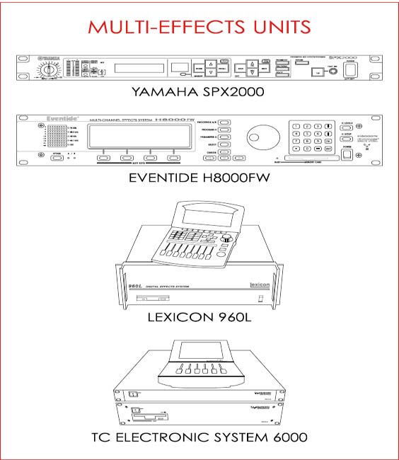
MULTITRACK RECORDERS
Multitrack recorders (MTR) allow for operators to capture numerous sound sources simultaneously, while storing them in isolation, i.e. several instruments may be recorded at the same time onto their own unique track. This provides great control over productions during the subsequent mixdown stage, e.g. a unique level balance between instruments may be generated, individual sources may be muted, etc.
Analogue tape machines were the first ‘sound on sound’ multitrack recorders utilised in commercial studios, evolving from two to three, four, eight, sixteen, twenty-four and thirty-two track capabilities. With the advent of digital audio, different devices took the place of the analogue tape recorder. Some of them are standalone, e.g. ADAT, RADAR, etc., while some, commonly referred to as DAWs, represent a combination of hardware, e.g. computer/ audio interface, and software, e.g. Logic Pro, Pro Tools, etc.
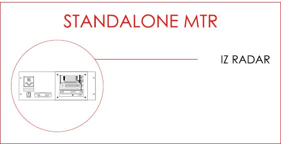
TWO-TRACK RECORDERS
Two-track recorders are commonly used to capture ‘reference’ or monitor mixes during recording sessions. Such devices are usually fed with the output signal from the console’s main stereo buss and are commonly kept running at all times during production, so as to capture any spontaneous ideas, dialogue between musicians, etc.
It is important to note that many recordists prefer to record the two-track mix onto the multitrack recorder itself.

THE DIGITAL AUDIO WORKSTATION (DAW)I
‘Digital Audio Workstation’ is the collective name given to the components that make it possible for analogue audio to be converted and stored digitally. The number of separate elements that sum up to a DAW may vary from one (a standalone recorder) to many more.
The following are examples of possible DAW configurations:
• Audio Interface > Computer (running Logic, Pro Tools, etc.)
• Standalone A/D (and D/A) Converter > PCI Card > Computer
• Standalone A/D (and D/A) Converter > Audio Interface > Computer.
The A/D – D/A Converter
The A/D – D/A converter is an extremely important element of the digital audio recording chain and may be found in standalone form or as part of an audio interface. Converters commonly offer balanced line level, XLR or ‘jack’ connections on the analogue end and can operate with one or multiple digital audio formats, e.g. AES/EBU, SPDIF, ADAT Optical, etc.
The output of standalone A/D converters is normally connected to the digital input of an audio interface, which is in turn linked to a computer via Firewire or USB connections. Some specialised devices work in tandem with computer PCI cards, bypassing the need for an external interface. The connection between such converters and their corresponding computer cards is commonly made through D-Sub links.

The Audio Interface / Sound Card
The audio interface may be described as the computer’s digital audio input device. It may incorporate the functions of an A/D – D/A converter or simply accept digital signals, routing them to a computer through a PCI card or via USB or Firewire links.
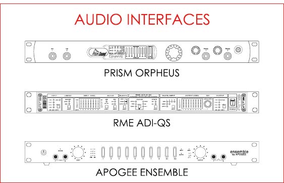
The Computer / Software Application(s)
A number of software applications are currently utilised for recording purposes, e.g. Cubase, Digital Performer, Logic Pro, Pro Tools, Record, Reaper, etc. With the passage of time, these are becoming increasingly similar and at present the choice of program appears to be a simple matter of taste, i.e. a good recordist should be able to work using any of the popular DAW software applications running on either a PC or Macintosh OS-based computers.
NB Other devices may be found as part of DAW systems, e.g. word clock generators, control surfaces, etc.
Word clock
Digital devices require a common clocking signal when operating as elements of the same signal chain. Such signal is referred to as word clock and it may be described as a series of electrical pulses occurring at regular intervals (matching the effective sampling rate).
The source of word clock must be extremely stable and as a rule of thumb, recordists should always set the clock output of the device of highest manufacturing quality in the chain as the ‘master’ (which may in some cases simply equate to the most expensive device acting as the timing reference).
Jitter
Inconsistencies in digital clocking may lead to a phenomenon known as ‘jitter’, commonly detected as the audio signal appears distorted or as ‘clicking’ sounds are produced by the system.
The most effective way to avoid jitter is to ensure that a single, exceedingly stable device is used as the word clock master and all other elements are set as ‘slaves’.
Control Surfaces
Control surfaces may improve the DAW workflow significantly, allowing recordists to operate the system with more efficiency.
Such devices may incorporate faders, switches, rotary encoders, etc. and may be very useful in recording sessions that do not incorporate an analogue console (‘in the box’), e.g. for the setting of ‘cue’ and stereo monitor mixes, etc.
THE MONITORING SYSTEM
The monitoring system, alongside the input to the signal chain, i.e. the transducers, should be given the highest priority in the audio path hierarchy. Without a fair and somewhat transparent evaluation of the material being recorded, production teams may work on the tracking stage of a project only to discover subsequently that the content gathered is less than ideal and does not correspond to expectations.
Monitoring systems may incorporate one or many of the following elements:
Power Amplifiers
Power amplifiers raise line level signals to loudspeaker level. This significant increase in voltage levels may be achieved in various manners and ‘amps’ can differ from each other considerably. Many of the factors that contribute to the aforementioned differences, e.g. topology, are beyond the scope of this book, which focuses on providing recordists with basic guidance.
The quest for clean, non-distorted sound reproduction should start with an investigation into amplifier and loudspeaker power. Equipment ‘spec sheets’ commonly display a number of different figures of varying relevance. One of these, ‘continuous power rating’ appears as the most important and realistic, as it describes the ability of a device to continuously handle ‘real-world’ program material. As a rule of thumb, the amplifier should present no less than twice (and ideally four times) the IEC continuous power rating of a connected loudspeaker with matching nominal impedance, e.g. a power amp with a continuous IEC power rating of 400 watts at 8 ohms should be used to feed a loudspeaker rated at 100 watts at 8 ohms (or at the very least a 200-watt power amp should be used). This ensures the amplifier will operate far below stress levels and with plenty of headroom.
Another important specification, known as ‘slew rate’ describes the ability of an amplifier to follow (react to) input transients and it is expressed in volts per microsecond. The slew rate dictates how high the input sensitivity of an amplifier (level) may be set to until it cannot reproduce transients faithfully. A very generic way to delineate suitable slew rates is:
| Rate > 10 V/µs Rate > 30 V/µs | For amplifiers rated under 100 watts per channel For amplifiers rated over 200 watts per channel |
Current high-quality power amps have slew rates that fall well above the described minimum range without presenting objectionable distortion or suffering from interference.
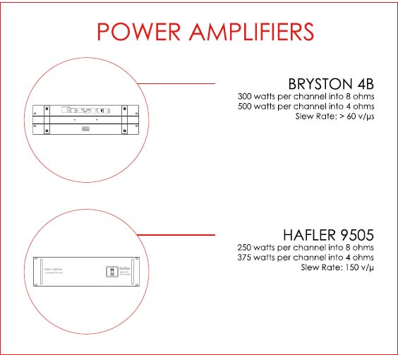
Loudspeakers
Loudspeakers are commonly the last and possibly the most important elements in the signal chain. Still, it is not uncommon for their selection to be heavily influenced by subjective criteria, where choice is based primarily on ‘character’ and not on fidelity (in a similar fashion to microphones). The topic of studio monitoring is a heavily debated one and it is approached with extreme caution by some, while others view it as a simple matter of taste. Despite the argument, it is nonetheless clear that different speaker models may be used effectively for music production as long as the technicians that employ them understand their behaviour.
A case may be made supporting the use of ‘flattering’ or ‘colouring’ monitors, considering that transparency may be virtually unobtainable for recordists working with restricted budgets and that ultimately most consumers will listen to music through uneven systems. With that in mind, it is not unusual for engineers to choose to work with loudspeakers that reproduce signals with a familiar bias or ‘colouration’, i.e. devices that superimpose a desirable uneven frequency response onto that of the program material. On the other hand, although it is possible for recordists to achieve good results with basic budget monitors, in the long run it seems advisable for them to seek for the ‘flattest’, most ‘truthful’ high-quality speakers, as such devices should lead to consistent results that translate well to a greater range of systems, e.g. from portable mp3 players to large PAs.
Specification Sheets
Specification or ‘spec’ sheets may help engineers wishing to choose their monitors using more than just personal taste. A few technical aspects appear as most important and should be taken into consideration during the selection process, including:
• Free-Field Frequency Response – This figure provides an overall view of a loudspeaker’s frequency response within an acceptable level of deviance (ideally within 1 dB and always below 3 dB), e.g. 50 Hz to 20 kHz, ± 1 dB. Such information is commonly presented in graphic form.
• Cut-Off Frequency (Lower and Higher) – The extreme ends of a loudspeaker’s frequency response, where reproduction is at a negative 3 dB deviation from unity gain, e.g. – 3 dB at 47 Hz and 22 kHz. This measurement may not be relevant in cases where the free-field frequency response of a loudspeaker is stated.
Maximum SPL – A general indication of the maximum output level for a frequency range at a given distance, which should be accompanied by a THD figure, e.g. maximum sound pressure level at 1 metre (100 Hz to 10 kHz) = 110 dBSPL (at 3 percent THD).
Total Harmonic Distortion (THD)
Total harmonic distortion is a measurement describing the nonlinearity of devices. THD is calculated through a comparison between the harmonic content at the input and output stages of a given piece of equipment. Total harmonic distortion may be expressed as a number or as a percentage and, as a rule, low THD values imply high quality in manufacturing. THD readings of 3 percent and higher should be considered unacceptable.
Driver Types
Loudspeaker drivers are transducers, converting electron flow into acoustic energy. This conversion is made possible by processes that are identical (although opposite in direction) to those employed by microphones. The following are the most common types of drivers found in loudspeaker enclosures:
• Dynamic – Moving Coil
The most popular design, moving coil drivers are very resilient and therefore able to reproduce sound at high levels (extreme excursions). They are suitable for operation at different frequency ranges and are used as sub-woofers, woofers and tweeters (varying in size).
• Dynamic – Ribbon
Ribbon drivers are fragile and suitable for high-mid / high-frequency, (relatively) low sound pressure level excursions only (tweeters).
• Electrostatic
Electrostatic drivers reproduce sound with minimal distortion and excellent timing, i.e. transient response, although at (relative) low output levels. Such drivers are not commonly employed for the reproduction of low-frequency sound content due to physical restrictions.
• Piezo
Piezo drivers are used for the generation of high / very high-frequency content by tweeters and super-tweeters (limited excursions). This type of transducer is found in some types of headphones, etc.
Cabinet (Enclosure) Design
Enclosures were designed to decouple the front and the rear of loudspeaker drivers, as the two are opposite in polarity, i.e. if drivers were to be simply suspended in mid-air, most low-end acoustic energy would be ‘cancelled’ as the back of a driver would ‘suck’ the air displaced at the front and vice-versa. An ideal way to avoid this ‘coupling’ would be to mount drivers on very large panels or ‘baffles’(ideally infinite in size), which would ensure the separation between their two poles, with no side effects (except for the loss of 50 percent of all energy created). As this is not practical, a few alternate ways to improve the efficiency of driver systems were devised.
• Sealed Enclosure
A sealed enclosure is a box with no openings or ports (except for very small air ‘leaks’). Such a box guarantees the separation between the front and the rear of the transducer, although a significant amount of energy is wasted. The air inside a sealed enclosure acts as a spring, opposing the movement of the cone and, as a consequence, closed cabinets must be relatively larger in size to allow for low-frequency reproduction.
Some individuals refer to mounted studio speakers as ‘infinite baffles’, although such devices’ behaviour is closer to that of sealed enclosures (without diffraction issues) as the air behind mounted drivers will still offer resistance to cone movement.
• Ported / Bass Reflex Enclosure
Ported cabinets have vents or openings that make it possible for air (and therefore energy) to escape the enclosure. Such design allows for an extended bass response from smaller units (through resonance), although this commonly comes at the expense of added ‘colouration’.
• Transmission Line
Transmission Line enclosures may be thought of as vented boxes with an added inner acoustic ‘labyrinth’, through which sound has to travel before reaching the outside. This allows for the energy from the rear of the driver to be (more) coherent with that of the front, as it reaches the open air (due to the delay in travel).
• Auxiliary Bass Radiator (ABR)
The Auxiliary Bass Radiator design is another attempt to utilise the energy from the back of loudspeaker drivers. In ABR cabinets, a ‘dummy’ (inactive) cone takes the place of a vent, reducing the stiffness of the ‘spring’ system of a closed enclosure, while using more of the rear energy (increasing efficiency).
Enclosure Shape
The shape of a cabinet affects how it will cope with internal pressure and how sound will diffract around it. For these reasons a few manufacturers have been moving towards rounded or curved designs.
Passive vs. Active Loudspeakers
Some loudspeakers, referred to as ‘active’, incorporate a built-in power amplifier. This implies they may be fed with line level signals, e.g. the main output of a mixing console. The advantages of such devices lie in the possibility of a perfect match between amplifier and drivers in the case of high-end manufacturers.
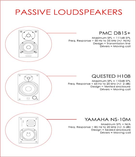

Headphones
Headphones play an important dual role in music production, being used not only by performers but also by recordists on occasion. As far as engineering with headphones is concerned, the following are advantages of working with such devices:
• Headphones tend to provide recordists with a greater level of detail than ‘middle of the road’ / low-quality studio monitors.
• Headphones allow for work to be carried out under ‘less than ideal’ control room circumstances or even within the performance space, i.e. the ‘live’ room.
• It is very likely that current productions will be auditioned (by the general public) through headphones more extensively than through any other speaker-based monitoring system.
With that in mind, it is still important to also note the following disadvantages of working with headphones:
• The stereo image of headphones is considerably different to that of loudspeaker systems (unless crosstalk and delay are introduced).
• Engineers tend to work more ‘conservatively’ when mixing with headphones (lower relative levels, e.g. vocals, and narrower stereo image).
Ultimately, as artists and other production personnel will commonly expect to audition ‘takes’ or monitor mixes through conventional monitoring systems, headphones should be used temporarily and always alongside loudspeakers.
Types of Headphones
• Closed
Example: Sony MDR-7506
- Greatest isolation (in both directions)
- Best for recordists working in the performing space
- Best for musician’s cues
- May cause physical fatigue
• Semi-Open
Example: AKG K141 MKII
- A compromise between isolation and comfort
- Isolation may be insufficient for cue mix use
• Open
Example: Sennheiser HD800
- Greatest comfort
- Poor isolation
Monitoring Management Devices
Monitoring management devices aim to provide large format console, control room monitoring capabilities to individuals working in smaller, ‘budget’ DAW-based studios. This type of equipment usually offers functions such as output level adjustment, input selection, output (monitor) selection, talkback, headphone outputs, etc.