
INTRODUCTION TO DIGITAL MULTIMEDIA
With Telephone and TV, it is not so much the message as the sender that is sent.
—Marshall McLuhan, Canadian sociologist
The world of digital video is indeed very challenging. It involves delivering video to devices as tiny as mobile screens and as giant as digital cinema screens. In between lies a wide range of devices, such as TVs, monitors, PDAs, and projection systems, all with varying sizes and resolutions. The delivery may be via terrestrial, satellite, or cable systems; direct-to-home (DTH) platforms; or IP TV, 3G networks, or digital mobile TV broadcast networks such as DMB or ISDB. All these are made possible by standards and technologies that define audio and video coding, transmission, broadcast, and reception.
The basic elements of the digital transmission system are, however, very simple. These comprise a still or moving picture and audio in one or more tracks. The audio and video are handled using compression and coding standards and transmitted using well-defined networks and protocols. An understanding of the coding formats, standards, and protocols and the standards for transmission is useful to understand fully the dimensions of mobile TV and other frontline technologies (Fig. 2-1).
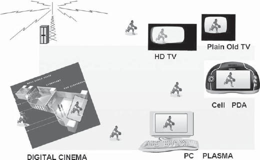
FIGURE 2-1 The Broadcasting Environment Today
In this chapter we look at audio and video and their compression with a focus on their carriage in mobile networks. Mobile networks are characterized by transmissions at speeds much lower than the standard definition TVs and require the audio and video to be compressed by very efficient algorithms such as MPEG-4. Mobile devices present a very constrained environment for applications owing to the limitations of power and processor memory capacity. This implies that they can handle only visual simple profiles of the video comprising limited objects suited for the tiny screens. We look here at the pictures, video, and audio and the manner in which they are compressed for handling on mobile networks.
The basic element of multimedia is a picture (Fig. 2-2). The picture in its native format is defined by its intensity, color, and size. For example, a picture presented on a full screen of a VGA (video graphics array) monitor would be represented by 640 × 480 pixels. The size of the picture file would be dependent on the number of bytes used to represent each pixel. For example, if a picture is stored as 3 bytes per pixel, picture size = 640 × 480 × 3 = 921,600 or 921 Kbytes. The image size is represented as 0.92 Mbytes and the picture quality is represented as 0.297 Mpixels.

The same picture on an XGA monitor (1024 × 768) would be displayed at a higher resolution with a file size of 1024 × 768 × 3 = 2359.2 Kbytes or 2.4 Mbytes. The picture resolution is 0.78 Mpixels.
2.2.1 Image Size
The size of the picture, represented by the number of pixels, has a direct bearing on the image file size. An image as transmitted for standard definition TV, (Consultative Committee for International Radio 601, CCIR 601) is represented by 720 × 576 pixels (or 720 × 480 for National Television Standards Committee (NTSC) standards), or around 300 Kpixels. The same image if seen on a mobile TV screen could be represented as 350 × 240 and would need only 82 Kpixels. A high definition (HD) TV transmission with 1920 × 1080 pixel representation will need 2 Mpixels to display one screen (Fig. 2-3).

FIGURE 2-3 Screen Size and Pixels (Pictures Courtesy of 3G.co.uk)
In general different screen sizes and resolutions can be represented by different pixel counts. The pixel count and its representation with respect to number of bits directly reflect the quality. There are a number of formats that have become common as a requirement for carrying video at lower bit rates and for lower resolutions. One of the early formats was the CIF (common interchange format), which was needed for applications such as videoconferencing that connect across national borders. As the Integrated Subscriber Digital Network (ISDN) lines supported only 64–128 kbps, full-screen resolution could not be supported. The CCIR H.261 video conferencing standard, for example, uses the CIF and quarter CIF (QCIF) resolutions. The CIF format is defined as 352 × 240, which translates to 240 lines with 352 pixels per line (this is well below the standard definition NTSC or PAL (phase alteration by line) TV signals, which would be represented as 720 × 480 (NTSC) or 720 × 576 (PAL)). The QCIF format (e.g., used in a Web page) has the requirement to carry or display only 178 × 144 pixels against 720 × 576 needed to carry CCIR 601 video. The use of CIF and QCIF notations is common in the telecommunications and Internet domains.

FIGURE 2-4 Image Representations
For television and broadcast applications, mentioning resolutions in the form of VGA or video graphics array is much more common as the cameras and other equipment provide PAL or NTSC signals or provide displays for computer screens that have VGA (or multiples of VGA) as resolution.
The VGA resolution is defined as 640 × 480 pixels. The VGA screen has 0.3 Mpixels. A quarter VGA (QVGA) is then 320 × 240 and has 0.0768 Mpixels. QVGA is a commonly used format in mobile TV applications, though VGA and CIF resolutions are also used.
QVGA is also called standard interchange format (SIF) and is used in video CDs. For higher resolution, XGA (1024 × 768) and SXGA (1280 × 960) resolutions are used. Figure 2-4 depicts the pixels recommended for various image size applications.
• There are other sizes that can be used to define an image. These can be 1/2 or 1/16 of a VGA screen (i.e., 160 × 120 or QSIF).
Most mobile phones today have high enough resolution to support either 320 × 240 or 640 × 480 resolution of images. Some of the high-end smart phones now come with cameras of 5 Mpixels, placing them in direct competition with digital cameras.
It is also possible to represent the same picture with different pixel counts as in a digital camera by varying its size.
2.2.2 Picture Quality
The picture quality is determined by the number of pixels used to represent a given screen size or area. For the same size of a picture, the quality can vary widely based on the resolution of the camera used (Fig. 2-5).
The need for high resolution can imply very large pixel counts for digital images, particularly for digital camera environments and other high-resolution requirements. For example, a digital camera can be programmed to have different pixel sizes for pictures meant for different purposes. The Kodak recommended image resolutions for different picture sizes are shown in Table 2-1.

FIGURE 2-5 Picture Quality by Pixels Using a Digital Camera (Images Courtesy of cnet.com)
Image Resolution
| Print size | Megapixels | Image resolution |
| Wallet | 0.3 | 640 × 480 pixels |
| 4 × 5 in. | 0.4 | 768 × 512 pixels |
| 5 × 7 in. | 0.8 | 1152 × 768 pixels |
| 8 × 10 in. | 1.6 | 1536 × 1024 pixels |
Inexpensive digital cameras today can support resolutions above 5 Mpixels, while mobile phones are available that can support from 1.3 to 5 Mpixels. The supported resolutions are going up rapidly.
2.2.3 Image Compression and Formats
The large file size of an image makes it almost essential that it be compressed for easy storage, transmission, and retrieval. Transmission of a picture in uncompressed format is not practical due to its large size and consequent time taken for its transmission. For use on the Internet and e-mailing the image sizes need to be much smaller than the uncompressed formats. There are several ways to reduce the file size, such as
• changing the picture size to suit the reception device.
• changing the number of bytes used to represent each pixel, and
• compression.
There are a very wide range of image formats and variants with different compression and techniques used, which have a bearing on the image portability and quality. For local storage and special applications (e.g., publication, large screen displays) it may still be necessary to handle images in uncompressed format.
JPEG image format: The JPEG format is one of the most commonly used image formats on the Internet as well as in mailing applications. This is because of its establishment as an international standard for images. The JPEG encoders work by dividing a picture into macroblocks of 8 × 8 pixels and applying the DCT (discrete cosine transformation) process (Fig. 2-6). The higher coefficients are then discarded, leading to a reduction in the file size. The reduction depends on how many coefficients one is willing to discard and correspondingly the loss acceptable in compression. The quantized values are further compressed using “lossless” Huffman coding.
The entire process of compression using DCT is based on the fact that the human eye cannot perceive fine details that are represented by higher frequency coefficients, which can be easily discarded without discernible loss of quality. Hence it is desired to convert the image from the format represented by shades of gray for each pixel to a format in which a block of cells, called a macroblock (8 × 8 pixels), is represented by various frequency components. The value coefficients denoting each frequency are then picked up by “zigzag scanning,” which ensures that the series of values that are generated begins with the lower frequencies and the higher frequencies follow later. It is possible to truncate the series by rejecting the elements in the series that are very low in value (representing the higher frequencies).

FIGURE 2-6 Compression Using Discrete Cosine Transformation
As shown in Figs. 2-6 and 2-7 the higher frequency components fall in the right bottom of the DCT table after the DCT transformation and are discarded. Because the picture can be efficiently represented by the lower frequency components falling in the upper left triangle, these are retained and represent the picture without discernible loss of quality to the human eye. The reduction in picture size depends on how many DCT coefficients are retained. In most cases a 20:1 compression can be achieved without discernible loss of quality.
The compression is achieved by rejecting higher frequency components—and hence these cannot be recovered again. The compression is thus “lossy” and the original picture with full resolution cannot be obtained back from a compressed image. It is for this reason that images that are needed for studio work and editing are stored in an uncompressed format.

FIGURE 2-7 DCT Quantization Using Zigzag Scanning, Which Prioritizes Lower Frequency Components
The JPEG formats support 24 bits per pixel (i.e., true color) and is good for images with large variations in color.
JPEG files are stored using the .jpg extension and are widely supported by browsers as well as virtually all applications. The compression that can be effected by JPEG is usually determined by the extent of picture degradation that can be accepted.
The GIF format: The GIF format was originally developed by CompuServe in 1980 and has been a de facto standard for image storage and transmission since then. It is virtually a lossless compression. The GIF format uses the LZW compression technique and is efficient at condensing color information for pixel rows of identical color by limiting the color palette to 16 or 256 colors. It is particularly effective for drawings and sketches with large areas of the same color. There are two variants, the GIF87a, which supports 8-bit color (256 colors) and interlacing, and GIF89a, which in addition supports transparency and animation. GIF files are saved using the .gif extension and have universal browser support. The GIF format is a Unisys patented technology.
Portable network graphics (PNG) format: The PNG format is a 24-bit format (lossless) and is good at compressing images with large areas of similar color. It is very similar to GIF and is primarily an open source standard. The PNG format supports progressive scanning of images and is superior to GIF in this regard. Due to its large file size such images are not commonly used in transmission on Internet or mobile networks. PNG files are denoted by the .PNG file extension.
BMP format: The BMP is the bit-mapped graphics format defined by Microsoft and commonly used in the Windows environment. BMP reduces the file size by supporting 1-, 4-, 8-, or 16-bit color depth. The images can be uncompressed or have RLE compression. Because of this the file size is very large. The files have the .bmp extension.
When there is motion, there is a need to convey continuous information of the objects in motion, which brings us in the realm of video. The handling of video is based on the principle of the persistence of vision of the human eye, which cannot distinguish rapid changes in scene. Taking advantage of the persistence of vision it is possible to transmit a series of pictures (called frames) at a rate at which the human eye would not see any discontinuity in the motion. This is the principle used in cinema projection, in which 24 frames are shown with each frame being shown twice to bring to a refresh rate of 48 frames per second to provide a feeling of continuous motion.
2.3.1 Video Signals
Motion is typically recorded by cameras that capture a series of pictures called frames, which are then passed on in the form of a video output. In addition a camera could also provide one or more audio outputs associated with this video. Each frame essentially represents a picture and the motion is captured by transmitting either 25 or 30 frames per second (based on NTSC or PAL standards). The persistence of vision in the human eye is adequate to make the motion appear seamless.
The handling of video thus implies transmission of a number of frames every second. The resolution of the picture (i.e., the bits in each frame) and the frames transmitted per second define the bit rate needed to handle a particular video signal.
2.3.2 Generation of Video: Scanning
The first step in the generation of video from pictures is the process of scanning a picture. A camera typically measures the intensity and color information in a picture by scanning a horizontal line across the picture. A series of horizontal lines are used to complete the full picture.
In the analog domain, the scanning process generates a series of levels (amplitude vs time) representing the variation of the picture from white to black. The process generates a waveform representing each horizontal line until all the lines are scanned and converted into the analog waveform to complete a frame. The number of horizontal lines used to scan a picture completely is defined in a frame. The lines are separated by a vertical blanking pulse (Fig. 2-8).

Analog video signals as we know them today had their origin in analog video cameras with plain sensors with a light sensitive device that generated a voltage in proportion to the light falling on it. For this purpose it was necessary to make the light from a small element of the picture fall onto the sensor to create an accurate representation. Initially the sensors were monochromatic, i.e., they generated a voltage representing a point in terms of various shades of gray. This also led to the pictures being created in a monochromatic format, commonly called black and white. The process of scanning involved having to cover all points in the entire picture and the concept of scanning of pictures as we know them today became a well-established practice. Color sensors introduced later provided three signals, i.e., red, green, and blue, to reconstruct a picture element (Fig. 2-9).
The scanning had to be repeated a number of times each second to cover motion and these sequentially scanned pictures were known as the frames. Different standards emerged with frame rates and the way the color information is handled, but, broadly, the frame rate converged into two standards, i.e., 25 and 30 frames per second.
Interlaced and progressive scanning: When the pictures were scanned at a frame rate of 25 or 30 frames a second there was a visible flicker owing to the time gap between the frames (i.e., 25 frames per second scanning gives a time between frames of 40 msec, while a 20-msec refresh is needed to give a flicker-free viewing experience). Hence the techniques that had been used in the motion picture industry for quite some time needed to be used, although in a slightly different manner. A film projector shows each frame twice to reduce flicker. In the days of analog signals this could not be implemented easily as there was no way to store the frame. Hence a new mechanism called interlaced scanning was used. The frame was divided into two halves, each containing about half the lines, called a field. The first field displayed the odd numbered lines while the other displayed the even numbered lines.

FIGURE 2-9 Scanning in a Television Frame
This technique was called the “interlaced scan” and worked very well with television screens. While one field was being displayed, the previous field could still be viewed, as the phosphor used in the CRT tube continued to emit the light. The persistence time made for a much better viewing experience than having to repeat the frames, while at the same time did not require twice the bandwidth or complicated circuitry for frame storage. The interlaced scanning of the analog world continues today in the television world.
Interlaced scanning has, however, many disadvantages when extended to the digital or image processing world of digital technology. When computer monitors were first introduced, they produced a visible flicker with interlaced scan display due to the need to display sharp character images. The progressive scan, by which all the lines of the frame were scanned in the same frame, was a better option particularly as there were no bandwidth restraints in the local circuitry (Fig. 2-10).

FIGURE 2-10 Interlaced Scan and Progressive Scan

FIGURE 2-11 Composite and Component Video
The emergence of video editing also required that there be one standard of video signals that could be processed internally, while the transmission systems continued to have divergent standards.
Color: The human eye has sensors that perceive light in three colors, i.e., red, green, and blue (called RGB in the video world). While this is a good way to represent the signals for processing, it has been more convenient to have the luminance and the color components carried separately. In a “black and white” TV, only the luminance signal is used, and historically, because at first all TV sets were monochrome, only the luminance component was used. For reasons of backward compatibility, the technology of transmission of the luminance and color signals separately was adapted for color TV. The monochrome monitors could continue to display the Y (luminance) signals only, while the color TV sets could use all the signals, for the same transmission.
The mapping is done by representing the luminance as Y and the color components as U (representing B – Y) and V (representing R – Y) (Fig. 2-11). As the human eye perceives color details at lower acuity than luminance, the bandwidth of the color signals is kept lower than that of luminance. For example, in PAL, the luminance channel is transmitted at a larger bandwidth, of 5.5 MHz, while the U and V channels are transmitted at 1.5 MHz. Similarly in NTSC the color channels (called I and Q) are transmitted at bandwidths of 1.3 MHz and 400 kHz, respectively, against that of luminance, which is 4.2 MHz (Fig. 2-12).
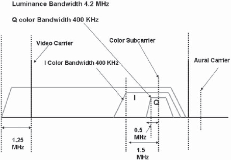
FIGURE 2-12 NTSC Composite Signal
2.4 TELEVISION TRANSMISSION STANDARDS
2.4.1 Analog Video
Historically video has been handled in an analog format, a practice that continues today. While there was a move to complete the digitization of TV by 2006 in the United States, by 2012 in Europe, and by later dates in other countries, the receivers in most countries continue to remain analog.
The NTSC standard is used in the United States, Japan, Canada, Taiwan, and Central America, among others. It is based on 480 scan lines per frame. After adding more lines for carrying the sync, vertical retrace, and closed caption data requirements, the total number of transmitted lines per frame is 525 lines. NTSC uses a transmission rate of 30 frames per second.(or 60 interlaced fields per second, matching the power line frequency of 60 Hz). This gives a scanning line frequency of 30 × 525 or 15.750 kHz. This type of transmission is sometimes referred to as NTSC 480i, where “i” stands for interlaced transmission.
2.4.2 The PAL Standard
In Europe, Asia, and some other countries, the PAL standard is used. PAL has 576 scanned lines per frame and a frame rate of 25 frames per second (or 60 interlaced fields per second). The actual number of lines transmitted is 625 lines per frame after adding the lines for sync, retrace, and data.
Analog video comprises the color components R, G, and B, which may be carried separately on three different wires or cable for local connectivity. This type of video carriage is known as the component format. Computer monitors usually have connectors for accepting the RGB component format video. In practice, rather than the RGB signals, the YUV combination is used to provide compatibility with monochrome devices.
2.5.1 Composite Video
Where the carriage of signals is involved over medium distances (e.g., within a facility) the three-cable method proves cumbersome and instead a composite video signal is used. A composite video signal comprises the luminance component (Y) modulated with a color subcarrier.
The NTSC standard uses the QAM modulation of the two color components, while the SECAM standard uses frequency modulation.
The composite analog signals have certain disadvantages. As the luminance component and the chrominance subcarrier are added together the two signals overlap to some extent. This results in “cross-luminance” effects in the receiver decoder by which color information is interpreted as luminance and vice versa. There are techniques such as comb filters or motion-adaptive filters to overcome these problems. However, their use is feasible only in the professional environment.
2.5.2 S-Video
S-video avoids the cross combining of luminance and chroma components by keeping the two separate. This means that the video is carried using two cables, one carrying the luminance (Y) and the other carrying the chrominance (C). S-video connectors have been frequently used in higher grade home video equipment.
Digital video is generated by the sampling of analog video and audio signals. The CCITT (now ITU) in 1982 had specified the standards for broadcast quality video under its recommendation ITU-R BT601. As per the Nyquist theorem the sampling rate should be at least twice the highest frequency. In practice, a sampling rate of four times the color subcarrier frequency is used to prevent aliasing.
2.6.1 Sampling of Composite Video Signals
In accordance with the 4xfsc (i.e. 4 times the frequency of subcarrier) sampling principle the PAL signals are sampled at 17.7 MHz and the NTSC signals are sampled at 14.3 MHz. ITU-R BT 601 specifies standardization at 8/10 bits per sample. The coding at 10 bits per sample gives the following rates:
• NTSC 143 Mbps,
• PAL 177 Mbps.
In the case of sampling of composite signals the audio and video are both associated with the signal and can be reconverted to a composite analog signal at the other end.
The above sampling gives rise to uncompressed video, and these are used in the D-1 and D-2 standards.
2.6.2 Sampling of Component Video Signals—Digital Component Video
Analog component video signals comprise Y (luminance) and U and V color signals. This virtually amounts to three parallel channels (Y, U, and V), each of which needs to be sampled and transmitted. For professional applications it is usual to code component video rather than the composite video signal. This implies the individual sampling of Y, U, and V signals. As in the case of analog component video, an advantage can be taken by sampling the color signals at lower rates than the luminance signal without perceptible loss of quality. For this purpose it is usual to code the U and V components at half the bit rate of the luminance component. This is denoted by the nomenclature of YUV samples as 4:2:2, i.e., for every four samples of Y there are two samples of U and two samples of V. This is accomplished by using half the sampling rate for the color signals U and V so that the number of samples generated is half that of the Y samples. The 4:2:2 format of component digital video is used in studio applications.
It is further possible to reduce the bit rates by sampling the color only on alternate slots. This gives rise to 4:2:0 notations for the sampling employed. The following is the ITU 601 table presenting the various sampling techniques employed for component digital video.
Component digital video sampling—analog signals
• 4:2:2 sampling: luma at 13.5MHz, chroma at 6.75MHz (2 × 3.375MHz)
• 4:1:1 sampling: luma at 13.5 MHz (4 × 3.375 MHz), chroma at 3.375MHz
• 4:2:0 sampling: luma at 13.5 MHz, chroma at 6.75 MHz (interlaced)
• 4:4:4 sampling: luma and chroma sampled at 13.5MHz
2.6.3 Color Video—Digital Formats
The digital domain deals with pixels. In line with the treatment of color, which is down-sampled at half the rate in standard definition (CCIR 601) TV, the digital transmissions also use scaling down the carriage of color information by a factor of 2. This is termed 4:2:2 and only the alternate pixels will carry U and V information. This can be represented by Y-U-Y-V-Y-U-Y-V.

For CIF and QCIF signals CCIR has provided for a lower sampling rate of 4:2:0 for the chroma signals. This implies that the sampling is downsized by a factor of 2 horizontally (i.e., pixels per line) as well as vertically (i.e., number of lines per field). This leads to the following representation:
Common intermediate format: CIF provides 288 lines of luminance information (with 360 pixels per line) and 144 lines of chrominance information (with 180 pixels per line).
Quarter common intermediate format: QCIF provides 144 lines of luminance (with 180 pixels per line) and 72 lines of chrominance information (with 90 pixels per line).
Table 2-2 lists the CCIR recommended video standards.
2.6.4 Interlaced Scanning vs Progressive Scan for Small-Screen Devices
The small-screen devices (CIF and below) use progressive scan instead of interlaced, as given in Fig. 2-13 (the progressive scan is denoted by “p” and interlaced scan by “i”).

FIGURE 2-13 Display on Small-Screen Devices
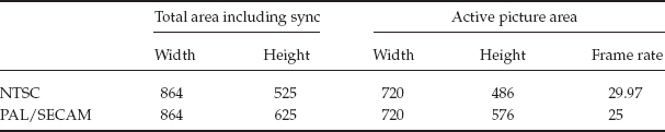
Active Picture Areas Used in Digital Standards
2.6.5 Line Transmission Standards for Digital Component Video
In studio practice it is also necessary to carry audio along with video signals. This is achieved by sampling the audio and combining the audio streams with digital component video. These are then carried on a common digital stream. The serial digital interface (SDI) format is an example for this type of carriage.
It is important to recognize that the analog signals have a sync interval, which is not necessary to code in a digital signal as the same can always be generated at the other end where the component video is to be given to a display device. In addition there are ancillary data spaces owing to some of the lines not being used in analog video because of tube characteristics. These lines outside the active area are not sampled (Table 2-3).
The capacity available through the inactive lines (horizontal ancillary area) and the vertical blanking (vertical ancillary areas) is used to carry pairs of stereo audio channels. In the case of NTSC the capacity so available can carry data rates of up to 5.7 Mbps. In Audio Engineering Society (AES)/European Broadcast Union (EBU) format two audio channels can be carried at a data rate of 3.072 Mbps. Thus two to four channels of audio are carried along with component digital video to generate the SDI signal. When audio is so embedded with video it is called the SDI format with embedded audio.
The standards for serial digital interface have been set by the Society of Motion Picture & Television Engineers (SMPTE) and are summarized below (SMPTE 259M-1997):
• Level A—143 Mbps, NTSC;
• Level B—177 Mbps, PAL;
• Level C—270 Mbps, 525/625 component;
• Level D—360 Mbps, 525/625 component.
As may be seen, the uncompressed rates are very high and are not generally suited to transmission systems or broadcast TV. It becomes necessary to compress the video for carriage or distribution. Video compression is always lossy and while compressed video is well suited to viewing without perceptible loss in quality, it is not ideal for studio handling and processing. For studio use, editing, and video processing uncompressed digital component video is preferred.
SDI video at 270 Mbps is a commonly used standard for professional use in studios, broadcast systems, and a variety of other video handling environments for standard definition video. However, for most transmission and broadcast applications there is a need to reduce the bit rates while maintaining acceptable quality. There are two techniques for the bit-rate reduction of video. These are scaling and compression.
2.7.1 Scaling
In applications in which a smaller window size can be used, the number of pixels and consequently the bits required to carry them can be reduced. This type of scaling is called spatial scaling.
In temporal scaling, bit rates can be reduced for certain applications by reducing frame rates. This is particularly true for frames in which motion is limited, such as video of a person talking. An example is the RealVideo streaming application, which can drop the frame rates from 30 (or 25) to 15 frames per second (fps) or even lower.
2.7.2 Video Compression
Compression of video is a complex process and a number of techniques are employed to compress video by factors of 100 or more while maintaining quality for designated applications. The compression of video builds on the techniques for compression of pictures such as JPEG compression using DCT. As each frame represents largely the same picture with motion in some areas of the picture, the techniques of frame prediction and interpolation are used in addition to the compression of the picture itself represented in the frame.
Compression of video can be lossy or lossless. In the case of lossy compression (such as dropping of bits or coefficients in the compression algorithms) the original picture cannot be restored with full resolution. All the compression techniques take advantage of the redundancies that are present in the video signal to reduce the bit rates of video for use in digital TV, mobile and IP TV, and other networks.
Spatial redundancy: In normal pictures, there are areas where the pixels would all depict the same object, e.g., sky or clouds. In such cases the variation from one pixel to another is minimal and instead of describing each pixel with all Y and color information bits, these can be coded by using the statistical redundancy information. A code such as run-length encoding (RLE) allows frequently occurring parameters to be carried using fewer bits.
Temporal redundancy: A video comprises a series of pictures (called frames), each of which is carried using a number of pixels that describe each frame. In the case of motion, each frame has some pixels that will change with respect to the previous frame as a result of motion. However, this is not the case for all pixels in the frame, many of which would carry the same information, as the frame rate is quite high (e.g., 25–30 fps). Hence, conveying all the information in a frame every time it occurs, as if it were totally unrelated to the previous frame, is not necessary. It is in fact possible to convey the change information (denoted as change or motion vectors) between one frame and the next. It is also possible to predict some frames based on the motion vector information. Every time all the information in a frame is carried it is called an I frame, while frames that are predicted using the motion vectors from previous frames are called P frames as per the notion used in MPEG-2 compression. There is another type of predicted frame called the B frame, which is predicted using the I and P frames, using the previous as well as the next (forward frames) as reference.
Temporal or interframe compression is possible owing to a large amount of common information between the frames, which is carried using only motion vectors rather than full frame information.
Perceptual redundancy: The human retina and the visual cortex are inherently able to distinguish the edges of objects with far superior acuity compared to the fine details or color. This is perhaps because of the greater need to distinguish objects rather than their fine details in the process of the evolution of living beings. This characteristic of the human vision is used to advantage in object-based coding in some higher compression protocols, such as MPEG-4, which use contour-based image coding.
Statistical redundancy: In natural images, not all parameters occur with the same probability in an image. This fact can be used to code frequently occurring parameters with fewer bits and less frequently occurring parameters with a larger number of bits. This type of coding enables the carriage of a greater number of pixels with fewer bits, thereby reducing the bit rate of the stream. This technique, called Huffman coding, is very commonly used in compression algorithms.
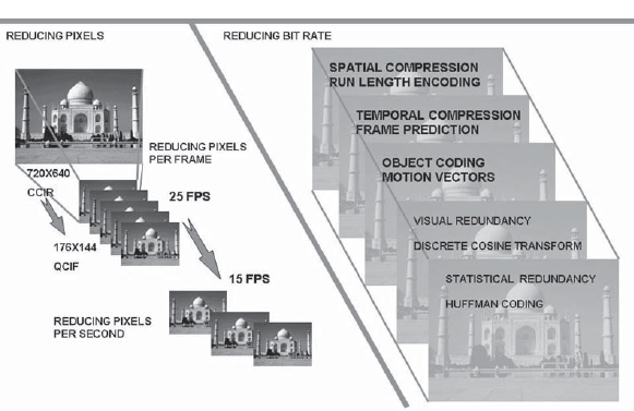
Scaling: reducing pixel count: An important parameter for the bit rate of a signal is the number of pixels that are required to be carried. A picture frame with a large number of pixels implies the coding of each pixel for carriage and thereby a larger frame size after coding. As the frame rate is generally fixed at 25 or 30 fps for broadcast applications, this translates into a higher bit rate for the stream. As an example, while the CCIR standard for standard definition video is 720 × 480 (345.6 Kpixels), which is used in broadcast television, MPEG-1 format, which is used to carry “VCD quality” video, uses a resolution of only 352 × 288 (101.3 Kpixels), thus reducing the number of pixels to be carried by one-third. The 352 × 288 is denoted the SIF, or standard interchange format. The standard used for video conferencing that is to be carried over multiple 128 K telephone ISDN lines using H.261 uses only a quarter of the SIF pixels by using 176 × 144 as the pixel density (25.3 Kpixels). A video conference that uses QSIF is thus using 25.3 Kpixels per frame rather than a standard definition broadcast video bit rate of 345.6 Kpixels, i.e., a pixel rate that is lower by a factor of 13 (Table 2-4 and Fig. 2-14).
Bit Rates for Small-Screen Devices Using Commonly Used Compression Formats

It is very easy to visualize the processes that are involved in the two areas, i.e., scaling and compression, for reduction of bit rates. As an example consider the case of PAL video with a CCIR 601 resolution of 720 × 480. This implies 345.6 Kpixels per frame. At the transmission rate of 25 fps it translates into 8.64 Mpixels per second. For carriage of such video over the Internet or mobile TV it could be reduced to QCIF with a resolution of 176 × 144 or 25.3 Kpixels. If the frame rate used is 15 fps, the pixel rate needed to carry the scaled down picture is 0.38 Mpixels per second. In the above example, by scaling the picture and the frame rate, the pixel rate has been reduced from 8.64 to 0.38 Mpixels, which is a scaling of approximately 23 times.
The pixels are now ready to be subjected to compression, the first stage of which would begin by formation of 8 × 8 macroblocks and application of the DCT process, Huffman coding, run-length coding, and object-based coding, etc., based on the compression protocol employed. Once the entire process is completed, a bit rate as low as 64 kbps is needed to carry the information, which would otherwise have needed 9.12 Mbps to carry the scaled down video rate of 0.38 Mpixels per second at 24 bits per pixel.
MPEG stands for the Motion Pictures Expert Group, and compression standards formulated under the auspices of MPEG have been widely used and adapted as international standards.
The MPEG divides a video, which is a series of pictures or frames, into “groups” of pictures. Each picture in the group is then divided into macroblocks. The macroblock for color pictures under MPEG comprises four blocks of luminance and one block each of U and V color. Each block is made up of 8 × 8 pixels (Fig. 2-15).

FIGURE 2-15 MPEG Compression Process
The DCT quantization process for each frame is the same as that used for images. Each 8 × 8 block is transformed into another 8 × 8 block after DCT transformation. The new 8 × 8 block now contains frequency coefficients. The upper left corner of the block contains the lower frequencies and these are picked up for transmission. The lower right corner contains higher frequency content, which is less discernible by the human eye. The number of coefficients dropped is one of the factors in determining the compression. If no coefficient is dropped the picture compression is lossless and can be reversed by an inverse discrete cosine transformation process.
2.8.1 Motion Prediction and Temporal Compression
The group-of-pictures feature is used in temporal compression. The group of pictures carries three types of frames.
1. Intraframe or I frame: These frames are coded based on the actual picture content in the frame. Thus each time an I frame is transmitted it contains all the information of the picture in the frame and the receiving decoder can generate the picture without any reference to any previous or following frames. Each I frame contains picture information based on blocks that have been compressed using the DCT process.
2. Predicted frame or P frame: The P frames are generated from the previous I or P frames by using the motion vector information to predict the content.
3. Bidirectional frame or B frame: The B frames are generated by an interpolation of the past and future I and P frame information using vector motion information. The encoder has the frame memory and the transmission order of the B frame, which has been generated by interpolation, is reversed so that the decoder finds the frames in the right order.

FIGURE 2-16 Temporal Compression in MPEG
The degree of temporal compression depends on the number of I frames transmitted as a ratio of the B and P frames. This would depend on the type of source video content and can be set in the encoders. The lowering of the data rate takes place because a B frame contains only about half the data contained in an I frame, and a P frame contains only one-third the amount of data.
The I frame, which represents a new frame that is coded independently, serves as a reference point and also to resynchronize if transmission is lost due to noise (Fig. 2-16).
2.8.2 Motion Vectors and Motion Estimation
The techniques of spatial compression using DCT largely address the compression of pictures. In order to compress video with moving images effectively, it is also necessary to employ techniques that directly target moving objects. Motion estimation is one such technique used in MPEG.
Motion estimation is done by comparing the positions of picture elements (macroblocks) in one frame with previous frames and estimating direction and magnitude of motion that is represented by motion vectors. The process is complex and encoder quality is determined by how accurately the motion can be estimated.
There are a number of compression formats that exist and are used based on the application. The existence of many formats also depicts the historical evolution of compression technology, which has become more complex with the lowering cost of processing intensive chips and systems.
2.9.1 MPEG-1
MPEG-1 (ISO 11172) was the first multimedia audio visual coding standard. MPEG-1 was designed for CD quality video and audio coding with a limited resolution. This resolution was defined to be the SIF and comprises 352 × 288 for PAL and 352 × 240 for NTSC. The frame rates are 25 fps for PAL and 30 fps for NTSC, as in the analog systems, but MPEG-1 uses progressive scanning in handling the video. MPEG-1 generates the compressed stream at rates up to 1.5 Mbps and has been largely used for delivery of audio/video content on CD-ROMs (sometimes called by the common name video CDs or VCDs). MPEG-1 uses the processes of DCT and run-length encoding as well as motion estimation based on pixel motion. MPEG-1 provides for up to two audio channels and three layers of audio coding complexity (Layers 1 to 3), of which Layer 3 is most popular and is known as MP3.
MPEG-1 does not address the streaming formats.
MPEG-2 (ISO 13818) is a compression standard that was finalized in 1994 and is today the most widely used standard for broadcast TV as well as storage applications such as digital video discs (DVDs). The MPEG-2 format was meant to handle the full range of video quality encountered in applications ranging from broadcast to studio processing and later extended to high definition video. MPEG-2 decoders can generate bit rates from 1.5 to 15 Mbps for standard definition video. The type of compression employed is selected through the use of the MPEG-2 profiles. For the transmission of broadcast quality standard definition video (CCIR 601) the “main profile at main level” (MP@ML) is used, which generates bit rates up to 15 Mbps. For studio processing of video the use of B and P frames is dispensed with and only I frames are used, resulting in a compressed video stream at 50 Mbps. The I-frame-only compression makes the compressed video suitable for frame-by-frame editing.
2.9.3 MPEG-2 Transmission Frame
MPEG-2 provides a unique structure for the transport stream whereby the stream can carry any number of video, audio, and data channels, which are identified by their program IDs and can be grouped together in any manner using Program Association Tables (or PAT) (Fig. 2-17).
MPEG-2 is also backward compatible with MPEG-1 and has provision for carriage on different transport media including streaming and ATM (ATM adoption layer).
MPEG-2 is the most widely used system today in digital broadcasting. The digitalization of the analog TV transmission networks is based on the use of the MPEG-2 transmission format and frame structure.
The MPEG-2 frame structure is also used in mobile TV broadcasting networks such as DVB-H.

FIGURE 2-17 MPEG-2 Transport Stream
2.9.4 MPEG-4 Compression Format
The MPEG-4 family of standards had their origin in the need to develop compression algorithms for new applications such as streaming and multimedia files transfer. The bit rates for such applications needed to be as low as 5 to 64 kbps for QCIF video. Along with better compression, higher functionality was an objective of MPEG-4.
This was accomplished by using an entirely different approach to video compression. The compression algorithms under the umbrella of MPEG-4 standards follow the approach of considering the video objects and the background as distinct and basic constituents of a picture. This is a departure from the approach used in MPEG-1 and MPEG-2 standards of using only pixels and blocks to describe the picture. Under MPEG-4 the picture is analyzed in such a manner so as to identify a single background (generally static) and a number of objects that are in motion. The objects are identified and compressed separately. Information on the motion of video objects is sent separately as part of the stream. The decoder then reconstructs the picture by combining the background and the individual video objects including their motion.
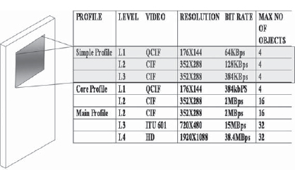
FIGURE 2-18 MPEG-4 Profiles for Mobile Devices
The MPEG-4 algorithms, which were primarily oriented toward providing high compression and lower bit rates than MPEG-2, have subsequently found applications in streaming video applications. The high compressions that can be achieved using MPEG-4 are the primary drivers that enable the HD transmissions within the manageable bandwidth of transmission systems (e.g., ATSC).
To cater to the wide range of applications that are possible using MPEG-4, a number of profiles and levels are defined. Figure 2-18 shows the bit rates generated by MPEG-4 for various screen resolutions.
The MPEG-4 visual simple profile is the prescribed standard for video and audio transmission over mobile networks under the 3GPP (3G Partnership Project) release 5 as explained in the next chapter.
In addition to these profiles, the standards for MPEG-4 have been enhanced to include advanced simple profile (ASP). The advanced simple profile provides for interlaced frame-based video to be coded using B frames and global motion compensation. MPEG-4 has also been augmented by adding the concept of enhancement layers. The basic level of encoding is the base layer, which contains the base level image quality as per MPEG-4 ASP (visual). One level of enhancement is provided by better picture quality per frame (also known as the fine grains scalability (FGS)). This improves the number of bits used to represent each picture or frame. The second layer of enhancement is provided by improving the frame rate or temporal enhancement (called the FGS temporal scalability layer).
As the MPEG-4 standards define a video object separately, it is possible to define three-dimensional objects as well and this makes the MPEG-4 standard ideally suitable for video handling for many applications such as video games and rich media.
The compression process under MPEG-4 has a number of steps, some of which are:
1. Identification of video objects: The picture is broken up into separately identified video objects and background.
2. Video object coding: The video object is then coded. The texture coding within the object is handled using the DCT process.
Multimedia and interactivity with MPEG-4: The high efficiency of video and audio coding achieved by the MPEG-4 were the initial success factors that led to its increasing use in various applications involving IP or streaming TV applications, including mobile TV. However, its wider scope in interactive and multimedia applications needs to be well recognized.
First, as its coding is object based, it can deal separately with video, audio, graphics, and text as objects. Second, synthetic (and natural) objects can be created and incorporated into the decoded picture. Third, as it uses object-based encoding rather than frame-based encoding, it provides flexibility in adapting to different bit rates. It is not limited by the need to transmit a certain number of frames per second, with repeated coding of the same object in the case of scene changes. This makes it ideally suited to mobile environments in which the user may travel from near a transmitter to the outer fringe and the usable bit rates may change considerably. Finally, it has a provision for scene coding called binary format for scenes (BIFS), which can be used to re-create a picture based on commands. This implies that objects can be reordered or omitted, thus virtually recompositing a picture with objects, graphics, and text. A picture can be rendered by adding or deleting new streams. When such changes are done based on commands (termed “directed channel change”), it can be used for a host of applications with powerful interactivity, such as targeted advertising. The BIFS information determines the source of the elementary streams in the final picture and these can be different from those from the originating source (Fig. 2-19).

FIGURE 2-19 Object-Based Decoding in MPEG-4
MPEG-4 Constituent Parts
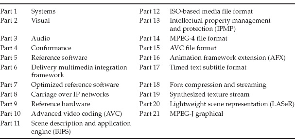
MPEG-4 has 22 parts, which define various attributes of the standard, such as Delivery Multimedia Integration Framework (MPEG-4 Part 6), Carriage over IP Networks (MPEG-4 Part 8), and Advanced Video Coding (MPEG-4 Part 10, now standardized as H.264/AVC) (Table 2-5).
MPEG-4 applications: Applications of MPEG include
• broadcasting,
• digital television.
• DVDs,
• mobile multimedia,
• real-time communications,
• Web streaming,
• studio postproduction
• virtual meetings,
• collaborative scene visualization,
• storage and retrieval.
MPEG-4 provides file structure in that the .MP4 files can contain video, audio, presentation, images, or other information. MPEG-4 files may or may not contain audio. Files carrying MPEG-4 audio are denoted by .MA4, while files carrying audio outside the MP4 container are denoted by .AAC.
2.10 H.264/AVC (MPEG-4 PART 10)
The H.264 coding standard was a result of a joint development effort of the Motion Pictures Expert Group and the Video Coding Expert Group and was released in 2003. The standard was adopted by the ITU in May 2003 under the H.264 recommendations and the ISO/IEC as MPEG-4 Part 10 (ISO 14496-10) in July 2003. The H.264 standard was oriented toward the twin objectives of improved video coding efficiency as well as better network adaptation. These are achieved by distinguishing between the two different conceptual layers, i.e., the video coding layer and the network abstraction layer. The H.264/AVC represents a significant improvement over the previous standard of MPEG-4 in terms of bit rates. The lower bit rates and the use of the network abstraction layer makes the H.264/AVC ideally suited to be used in wireless multimedia networks, CDMA, UMTS, and other packet-based transport media.
The H.264 standard has found wide acceptance for Internet, multimedia, and broadcasting applications ever since its release in 2003. 3GPP release 6 has adopted H.264 video coding as the standard for wireless and mobile broadcast networks, while 3GPP release 5 was limited to the use of the MPEG-4 visual simple profile. H.264 enables the transmission of video at bit rates that are half of those generated by MPEG-2. This together with better network layer flexibility and the use of TCP/IP and UDP protocols is leading to its increasing use in DSL/ADSL networks for IP TV as well as conventional broadcast networks, which are today completely dominated by MPEG-2. In the coming years with a reduction in the cost of the encoding and decoding equipment the transition to H.264 is expected to be significant.

FIGURE 2-20 Performance Comparison of MPEG Compression Standards, for a 120-min DVD-Quality Movie at 768kbps
The comparison in Fig. 2-20 reflects the bit rates and storage requirements using MPEG-2, MPEG-4 (ASP), and H.264.
MPEG-4 can deliver HD content at 7–8 Mbps against 15–20Mbps using MPEG-2. H.264 has been ratified as a standard in both the HD-DVD and the Blu-ray DVD formats. H.264 has also been built into the Apple QuickTime 7 as a video codec.

FIGURE 2-21 H.264/AVC Encoding
2.10.1 H.264/AVC Encoding Process
In the H.264 encoding process a picture is split into blocks. The first picture in an encoding process would be coded as an intraframe with-out use of any other information involving prediction. The remaining pictures in the sequence are then predicted using motion estimation and motion prediction information. Motion data comprising displacement information of the block from the reference frame (spatial displacement) is transmitted as side information and is used by the encoder and decoder to arrive at the predicted frame (called interframe). The residual information (the difference between intra- and interblocks) is then transformed, scaled, and quantized. The quantized and transformed coefficients are then entropy coded for interframe or intraframe prediction. In the encoder also the quantized coefficients are inverse scaled and transformed to generate the decoded residual information. The residual information is added to the original prediction information and the resulting information is fed to a deblocking filter to generate decoded video (Fig. 2-21).
Level 1 |
15Hz QCIF at 64kbps |
Level 1b |
15 Hz QCIF at 128kbps |
Level 1.1 |
30 Hz QCIF at 192kbps |
Level 1.2 |
15 Hz CIF at 384 kbps |
Level 1.3 |
30 Hz QCIF at 768kbps |
Level 2 |
30Hz QCIF at 2Mbps |
Level 2.1 |
25Hz 625HHR at 4Mbps |
Level 2.12 |
12.55 Hz 625SD at 4 Mbps |
Level 3 |
25Hz 625SD at 10Mbps |
Level 3.1 |
30Hz 720p at 14Mbps |
Level 3.2 |
60Hz 720p at 20Mbps |
Level 4 |
30Hz 1080 at 20Mbps |
Level 4.1 |
30 Hz 1080 at 50 Mbps |
Level 4.2 |
60 Hz 1080 at 50 Mbps |
Level 5 |
30 Hz 16VGA at 135 Mbps |
Level 5.1 |
30 Hz 4K X 2K at 240 Mbps |
2.10.2 H.264/AVC Video Profiles
This information is presented in Table 2-6.
A number of file formats are used in the multimedia industry. Many of the file formats have their origin in the operating systems used and the manner in which the files were sampled and held in store in the computers based on these operating systems. Others are based on the compression standard used. Conversions between file formats are today easily done by using a variety of software available.
2.11.1 Windows AVI Format (.avi)
AVI is the de facto standard for video on the Windows-based machines in which the codecs are built in for generating AVI video. AVI stands for audio and video interleaved and the audio and video data forms part in an interleaved manner in the AVI video (Fig. 2-22).

AVI is generated through sampling of audio and video inputs and does not have any significant compression. For this reason AVI files are used for storage but not for transmission over networks.
2.11.2 Windows Media Format (.wmv)
The Windows media format is a proprietary format of Microsoft and used on Windows Media 9 codecs and players. Despite being proprietary, due to wide deployment of Windows machines it is used extensively in a variety of applications. The use of .wmv files on other machines such as Mac requires Windows media software. Mobile TV broadcast networks in the United States such as Modeo DVB-H use the Windows media formats.
2.11.3 MPEG Format (.mpg)
As the name suggests the MPEG format denotes video and audio compressed as per MPEG-1 or MPEG-2 compression. The motion JPEG (MJPEG) files are also represented by .mpg files. MPEG being an international standard, operating systems such as Windows and Mac provide native support for MPEG.
2.11.4 QuickTime Format (.mov)
QuickTime is a proprietary format from Apple computers. It is widely used in the industry for audio and video as well as graphics and presentations. QuickTime, though proprietary, is closely aligned to standards at its core and has MPEG-4 as the base in QuickTime 6 and H.264/AVC in QuickTime 7. Due to the friendly and advanced features, QuickTime players are available for most operating systems.
2.11.5 RealMedia Format (.rm)
The RealMedia format has gained popularity through the universal use of RealMedia players and servers on the Internet. The basic versions of RealMedia Producer, Server, and Player have been available as free downloads and this has contributed to the widespread use as well. Over 80% of all Web sites support content hosted in RealMedia format and for this reason it is almost mandatory for any device accessing the Web to support RealMedia content.
The audio formats span a wide range depending on whether the audio is compressed or uncompressed and the standard used for compression. Many of these standards have a historical origin based on use (e.g., telecommunications systems such as PCM) or the operating systems of the computers used.
The audio standard used also depends on the application. Music systems require a different audio standard such as Dolby or DTS, whereas the audio on mobile handsets is based on highly advanced MPEG-4 audio coding such as advanced audio coding (AAC), while speech in GSM handsets may be based on adaptive multirate (AMR) coding.
2.12.1 Audio Sampling Basics
The range of frequencies audible to the human ear is 20 Hz to 20 kHz. In order to handle this audio range digitally, the audio needs to be sampled at least >2 times the highest frequency.
The rates of sampling commonly used are as follows:
• Audio CDs, 44.1 kHz at 16 bits per sample per channel (1.411 Mbps for stereo);
• DATs (digital audio tapes), 48 kHz at 16 bits per sample;
• DVDs, 48–192 kHz at 16–24 bits per sample.

FIGURE 2-23 Sampling and Coding of Analog Audio Signals
The large number of bits needed to code audio is due to the large dynamic range of audio of over 90 dB. Using a smaller number of bits leads to higher quantization noise and loss of fidelity (Fig. 2-23).
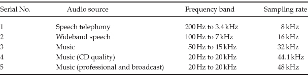
The process of sampling and coding generates pulse code-modulated (PCM) audio. PCM audio is the most commonly used digital audio in studio practice. The audio can be from multiple types of sources, each with a different bandwidth. The treatment in terms of the sampling bit rates is dependent on the type of signal and the quality desired.
From the perspective of mobile TV it is useful to distinguish between music (which is stereo audio of CD quality) and voice (which is mono and limited in bandwidth to 4 kHz). Some of the sampling rates commonly used are given in Table 2-7.
2.12.2 PCM Coding Standards
Owing to the logarithmic nature of the human ear in perceiving audio levels and the wide dynamic range involved, PCM coding is usually done using logarithmic coding. The A-Law and Mu-Law codecs, which have been standardized by the ITU under recommendation G.711, form the basis of digital telephony. The A Law is used internationally, while the Mu Law is used in the United States, Canada, and Japan, among others that follow the Mu Law coding convention. Both coding standards are similar and provide for different step sizes for quantization of audio. The small step size near zero (or low level) helps code even low-level signals with high fidelity while maintaining the same number of bits for coding. A-Law voice at 64 kbps and Mu-Law voice at 56 kbps are most commonly used in digital fixed-line telephony.
Audio interfaces: When the audio is coded, such as when using PCM or a coder, it consists of a bit stream. There is a need to define audio interfaces that prescribe the line codes and formats for the audio information.
AES-3 audio: The physical interface of audio has been standardized by the AES and the EBU under the AES-3/EBU. This physical interface provides for a balanced shielded pair cable that can be used up to around 100 m. Because they need to be carried on cable for such distances, the signals are coded with a line code. In the case of AES-3 an NRZ (non-return to zero) code is used with BPM (biphase mask) in order to recover the digital audio at the distant end. The AES-3 can carry uncompressed or compressed audio and is most commonly used for carriage of PCM audio.
Commonly used AES bit rates are as follows (for two audio channels):
• 48 kHz sampling rate, 3.072 Mbps;
• 44.1 kHz sampling rate, 2.822 Mbps;
• 32 kHz sampling rate, 2.048 Mbps.
In most applications audio must be transmitted at rates that may range from 8–12 (cellular mobile) to 64 (digital fixed-line telephony) or 144 kbps (stereo music). There is thus a need to compress audio.
Audio compression is based on the characteristics of the human ear, which does not perceive all frequencies equally. The following are the main characteristics of the human ear of which advantage can be taken in introducing compression:
• Stereophonic perception limit: The ear does not recognize sound as stereo below 2 kHz and, hence, sound can be transmitted as mono for frequencies below this threshold.
• Hearing threshold: When the sound level is low, the human ear is most sensitive to the middle band. It is relatively insensitive to low-frequency and high-frequency sounds.
• Temporal masking: A high-level tone signal masks the lower level signals near this tone (i.e., raises the threshold of hearing). Lower level signals, which will not be heard, can be discarded in the compression process.
2.13.1 Audio Compression and Coding Principles
Audio coders use perceptual compression, which is used on the twin bases of human ear perception and discarding of irrelevant data. Subband coding is the most common technique, in which the spectrum is split into a number of subbands. The bands that would be masked by the louder components nearby are then discarded.
2.13.2 MPEG Compression
The MPEG has developed standards for audio coding, which are used widely in the industry. MPEG-1 audio coding uses the psychoacoustic mode.
For audio coding the MPEG-1 compression standard is most popular, and MPEG-1 Layer 3 (MP3) has been used widely over the Internet as streaming or downloadable audio. MPEG-1 has three layers, which denote increasing complexity of compression and encoding process. MPEG-1 Layer 1 is used in digital compact cassettes, while Layer 2 is based on the MUSICAM compression format. The MUSICAM format is also used in the digital audio broadcasting systems (which are replacements of the analog FM broadcast systems). MP3 is an Internet standard as well as being used in digital audio tape. The sampling rates provided for in MPEG-1 are 32, 44.1, and 48 kHz.
The MP3 format (MPEG-1 Part 3) is a standard for digital video and associated audio at bit rates up to 1.5 Mbps (VCD quality, as popularly known). The MPEG-1 standard has the following components describing video and audio:
• Part 1, MPEG-1 Program Stream;
• Part 2, MPEG-1 Video for CD;
• Part 3, MPEG-1 Audio;
• Part 4, Conformance;
• Part 5, Reference Software.
MPEG-1 Part 3 became very popular owing to the relatively low bit rates and good quality. It has been the de facto standard for downloading of music on Windows-based computers as well as mobiles, PDAs, and a host of other devices.
2.13.3 Advanced Audio Coding (MPEG-2 Part 7)
MPEG-2 has been the standard for digital broadcast TV since its introduction and is one of the most widely used standards in the industry. It is used in satellite television, DTH systems, and digital cable systems as well as consumer devices such as set-top boxes and DVD players. Over 100 million set-top boxes and 50 million DVDs that have MPEG-2 technology at their core are believed to be in use worldwide. MPEG-2 has the following components:
• MPEG-2 Part 1, Systems;
• MPEG-2 Part 2, Video;
• MPEG-2 Part 3, Audio;
• MPEG-2 Part 4, Conformance;
• MPEG-2 Part 5, Reference Software;
• MPEG-2 Part 6, DSM-CC;
• MPEG-2 Part 7, AAC;
• MPEG-2 Part 9, RTI—Real-Time Interface.
The AAC was developed as an improvement over the MP3 audio standard (MPEG-1 Part 3). The MPEG-4 AAC adds an additional tool called perpetual noise substitution, which removes the background noise to reduce the data rates. It also uses a tool called joint stereo coding, by which the similarity between the left and the right audio channels is used to remove the redundancy between them. The redundancy between consequent audio frames is reduced by using a tool called long-term predictor, which removes the stationary harmonic signals from the encoding cycle. The MPEG-4 AAC is backward compatible with MPEG-2 AAC. The AAC standard is well popularized through its use in Apple’s iPod and iTunes music store.
MPEG-4 AAC provides better quality than MP3 at the same bit rates. It also supports coding of multichannel audio. The AAC codecs have three profiles based on the environment in which they are used. These are the AAC-MP (main profile), AAC-LC (low complexity), and AAC-SSR (scalable sampling rate profile). AAC is a part of MPEG-4 audio coding standards.
The MPEG-4 audio standards comprise a family of standards that cater to a wide range of bit rates. The MPEG-4 container file includes the following:
• Song title,
• Album cover,
• …,
• Audio.
The audio files coded in MPEG-4 are denoted by the .MP4 or .MA4 suffix. The MPEG-4 container has multiple parts, including the title and album cover (comprising all information on the signal being transmitted). It is possible to apply digital rights management to MPEG-4 audio.

FIGURE 2-24 MPEG Audio Formats
2.13.4 Audio Codecs in MPEG-4
The MPEG-4 audio coding brings in much more complex algorithms with superior compression. The functionalities that are introduced in MPEG-4 include “multiple bit rate coding” and scalable coding. Variable bit rate coding algorithms are better suited to media in which streaming is involved and fixed rates of delivery cannot be guaranteed (Fig. 2-24).
The new techniques introduced in MPEG-4 AAC include:
• Speech codec HVCX (harmonic vector excitation coding) is used to code speech at 2 and 4 kbps.
• The CELP (code excited linear prediction) coder provides encoding from 6 to 18 kbps. The encoder has options for 8- and 16-kHz sampling rates (Fig. 2-25).
2.13.5 MPEG-4 High-Efficiency AAC V2
The HE-AAC V2, or AAC-Plus codec, as it is popularly known, is an improvement over the AAC coding because it can provide better bit rates without degradation of quality. This audio codec is very important owing to its adoption by the DVB as well as standards bodies such as the 3GPP and 3GPP2 for use on mobile and 3G networks. It is also the mandatory audio coding standard for Korea’s S-DMB (digital multimedia broadcasting) mobile TV system as well as the Japanese ISDB-T mobile TV system. It is used extensively for music downloads over 3G and 2.5G networks.
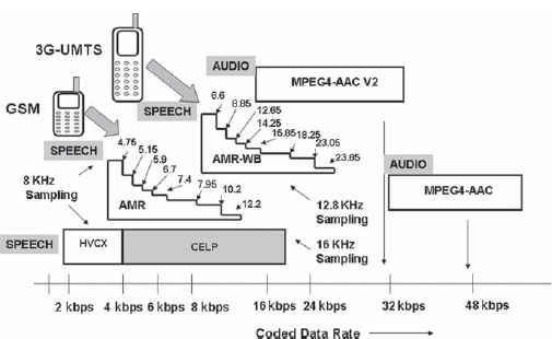
FIGURE 2-25 MPEG-4 Audio Encoder Bit Rates. MPEG-4 AAC V2 Codecs Can Provide Lower Bit Rates with the Same Quality Compared to MPEG-4 AAC Codecs.
In addition it is used in the U.S. satellite radio service XM Satellite Radio and other radio systems, such as Radio Mondiale, which is the international system of broadcasting digital radio in the short and medium wave bands (Fig. 2-26).
The AAC encoding is improved in two steps called V1 and V2. AAC V1 uses a technique called spectral band replication whereby the correlation between the high-frequency and the low-frequency bands is used to replicate one from the other. Version V2 goes further by adding another tool called the parameterized representation of stereo. In this technology the stereo images of the two channels (L and R) are parameterized and transmitted as monaural information together with difference signals. These are then used to reconstruct the signal.
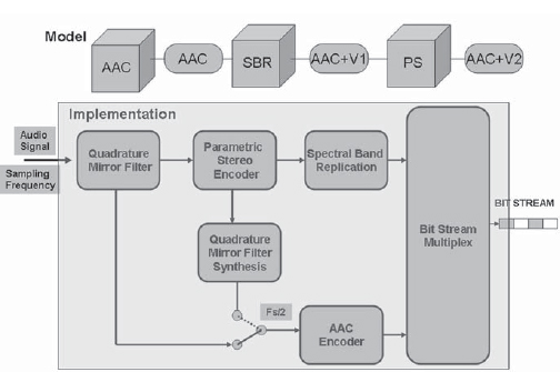
FIGURE 2-26 The AAC Family of Encoders
2.13.6 Proprietary Audio Codecs
Some of the codecs used in the industry do not fall under the MPEG umbrella. The prominent ones include Windows Media, Apple QuickTime, and RealAudio.
Windows Media 9 players are available as default on Windows-based machines and use Windows media codec V9. There is a wide range of sampling and encoding rates that can be selected depending on the application.
Apple QuickTime 7 supports a wide range of codecs including the choice of MPEG-4. Some of the proprietary options include the Qualcomm PureVoice codec for speech encoding, Fraunhofer II S MP3 audio codec, and Qdesign Music codec for music.
RealAudio from RealNetworks provides its proprietary audio codecs, which include the ATRAC3 codec jointly developed with Sony. The ATRAC3 codec provides high-quality music encoding from 105 kbps for stereo music.
In this chapter we have seen that the basic element of multimedia is a picture. The size of the picture in terms of the pixels determines the file size through which the picture can be represented. Mobile phones have screens that range from 1/4 of a VGA screen to QVGA or higher pixel counts. The size of the picture can be further reduced by compression schemes such as the JPEG. When there are moving images, they are carried as a series of pictures called frames. Commercial television systems carry 25 or 30 frames per second. It is common to reduce the bit rates for carriage of video by compression or reduction of frame rates. There are many schemes for compression, beginning with MPEG-1 and increasing in complexity. MPEG-2 is today widely used for carriage of digital television. MPEG-4 and H.264 are further developments that provide lower bit rates. With the mobile phones having small screen size such as QVGA and high compression such as MPEG-4, it is possible to carry video at very low bit rates ranging from 64 to 384 kbps. Audio needs to be similarly coded for carriage on mobile networks and a number of protocols have been developed for this purpose. These range from MP3 to AAC (MPEG-2 Part 7) and MPEG-4 AAC for music and AMR for speech. The use of advanced compression techniques makes it possible to deliver multimedia to the world of mobile phones.
Summary of File Formats
Picture file formats |
– |
BMP (*.bmp) |
Microsoft Windows bitmap |
GIF (*.gif) |
Graphics interchange format |
PNG (*.png) |
Portable network graphics |
JPEG (*.jpeg) or (*.jpg) |
Joint Photographic Experts Group |
WBMP (*.bmp) |
Wireless bitmap |
Video file formats |
– |
AVI files (*.avi) |
Audio video interleaved |
DV video files (*.dv, *.dif) |
Digital video |
MJPEG video files (*.mjpg, *.mjpeg) |
Motion JPEG |
MPEG-2 files (*.mp2) |
MPEG-2 |
MPEG-4 files (*.mp4) |
MPEG-4 |
QuickTime files (*.mov, *.qt) |
Apple’s QuickTime |
Raw MPEG-4 video files (*.m4v) |
Source MPEG-4 files |
Raw video files (*.yuv) |
YUV video files |
RealMedia files (*.rm) |
RealMedia video |
WAV files (*.wav, *.wmv) |
Windows audio and video |
MPEG-2 program stream files (.mpg) |
MPEG-2 program stream |
MPEG-2 video elementary files (*.m2v) |
– |
Audio file formats |
– |
MP3 files (*.mp3) |
– |
MPEG-4 audio files (*.m4a, *.mp4) |
– |
AAC files (*.aac) |
Advanced audio coding, MPEG-4 |
RealMedia audio (*.rma, *.ra) |
– |
WAV files (*.wav, *.wmv) |
Windows audio and video |
MIDI |
Musical instrument digital interface |
Some of the commonly used file formats found in various applications are given in Table 2-8.