
Chapter 6
Understanding Network and Storage in VMM 2012
Fabric has no product number. It is an abstract concept, not something you can order. It comprises all the components that together form the physical infrastructure of a cloud. Whether it is your private cloud, a hosted cloud, or Windows Azure (Microsoft's public cloud), the underlying infrastructure must be in place before it can be used to deploy a service consisting of one or more virtual machines and applications. This chapter contains the following topics:
- Creating Logical Networks and sites
- Creating IP pools and MAC pools
- Setting up load balancers and VIP templates
- Discovering and configuring storage arrays with Storage Management Initiative–Specification (SMI-S)
- Managing storage pools and assigning logical units
- End-to-end storage mapping from the VM to the array
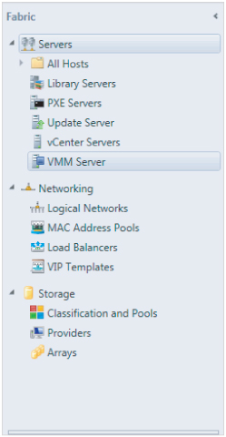
In VMM, the fabric is the domain of the VMM administrator, who can create, add, modify, configure, or remove the different fabric components. These are the three major building blocks:
- Networking
- Storage
- Servers
This chapter deals with networking and storage. Chapter 7, “Deploying Hosts and Clusters in VMM 2012,” deals with servers. Although the VMM graphical user interface (GUI) presents them in a different order, you should configure networking and storage before you deploy new Hyper-V servers or create a cluster out of standalone Hyper-V servers.
As you can see in Figure 6.1, servers, networking, and storage have further subdivisions.
Figure 6.1 The fabric
Preparing Network Integration
VMM helps you organize your networks for the private cloud into easy-to-grasp concepts. Although you should not need to add all your networking equipment to VMM or fully configure your entire network from VMM, doing so is certainly a very good start and network functionality in VMM will be expanded in the future. Networking is so well integrated into VMM that deploying virtualization hosts, virtual machines, and other services (including the applications that run on top of them) is easy.
VMM helps by organizing network subnets and VLANs into Logical Networks, IP address pools, and MAC address pools. Network load balancers and Virtual IP (VIP) templates are used to integrate network components with private clouds and services with flexibility and scalability in mind.
The previous version of VMM had network locations and network tags. These settings were used to place VMs and to determine whether networks on different hosts were the same. You could connect physical network adapters to different virtual networks, but only one address could be set as the location. A moving VM could, therefore, keep or correct connectivity with the proper network. The network tag could specify a specific purpose for a virtual network if it was attached to the same physical network. In practice, these network settings were rarely used.
VMM 2012 has better networking functionality, including features you cannot ignore as an administrator and that are easy to use if you are a self-service user. As we explained in Chapter 3, abstraction is the key word. The complexity of the network with its different VLANs, subnets, IP schemas, gateways, and DNS servers is masked from the private cloud consumer. It is up to the private cloud administrator to understand this complexity before setting up the network components of the fabric.
Although networks are usually tied to a specific location, their purpose may still be the same. Let's say you have a network for production and a network facing the Internet. These networks could each have one or more subnets—and it is quite likely that if you have multiple sites, these subnets will not be the same. For this reason, VMM offers the concept of Logical Networks. The Logical Networks LAN, DMZ, and WAN have different IP ranges on different locations (unless the network administrator has stretched VLANs). The Self-Service user, however, doesn't know about all these details and is just interested in connecting a VM to the LAN, the DMZ, or the WAN. Being able to use these simple and easy-to-understand logical names makes VMM Logical Networks a strong ally. The next sections describe how you can configure networking in VMM to make networks easy to use for self-service users and how you connect these networks to the different private clouds.
Configuring Network Settings
Before creating Logical Networks and sites, you should take a look at the network settings that determine how networks are automatically created when you add one or more existing virtualization hosts. The network settings can be found in the Settings workspace (bottom-left corner of the VMM Console window).
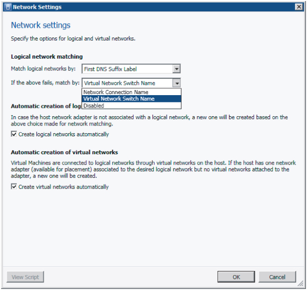
Under Settings → General → Network Settings, you can specify several options that define the general network settings to autocreate logical and virtual networks, which are enabled by default (Figure 6.2).
Figure 6.2 The Logical Network Matching options

Physical network adapters are matched with Logical Networks only when a host is added to VMM management and only when the host does not have any associated Logical Networks.
When a virtualization host is added to VMM, you can set whether Logical Networks are automatically created when a host network adapter is not associated with a Logical Network.
Similarly, you can either enable or disable the autocreation of virtual networks based on whether or not the host network adapter is connected to a Logical Network.
By default Logical Networks are automatically created under the described circumstances (Figure 6.3).
Figure 6.3 Global network settings
Creating Logical Networks and Network Sites
Logical Networks in VMM are especially helpful when you have a network across multiple locations. You will likely have Internet access on all locations; you could call that network Frontend, but have different definitions per site. In fact, a Logical Network is simply an abstraction of the physical network infrastructure that can be organized by a number of connectivity properties. A Logical Network is a combination of one or more network sites, each comprising an IP range, a subnet, and a VLAN. Once defined, a Logical Network can be easily applied to assign networks to virtualization hosts, single VMs, or a set of VMs that are part of a multitiered service. So, if the web tier requires Internet access, you just have to connect the Frontend network to it. As you will see later, you can also introduce load balancers and assign them to a host group and service in a similar fashion.
It is possible to have an empty Logical Network without any configured sites, but this will not add much functionality other than documenting that network. A Logical Network derives its functionality from its network site definition, which allows associations with VLANs and subnets to host groups. In VMM, IP subnets use a CIDR notation.
To create a logical network, follow these steps:
Figure 6.4 Naming the Logical Network

Figure 6.5 Associating the VLAN and subnet

If you want to change the properties of the Logical Network, go back to Fabric → Networking → Logical Networks and select the network to be changed.
Manually Removing Dependent Resources
You cannot delete a Logical Network if there are still dependencies on other objects, such as network sites, virtual network adapters, host network adapters, load balancers, or load-balancer templates. You must remove them before you can remove the Logical Network. You can check what dependencies are active by right-clicking the Logical Network and selecting View Dependent Resources.
In Figure 6.6, two Hyper-V servers depend on the Logical Network called Management. The Logical Network can't be removed until these dependencies no longer exist.
Figure 6.6 Dependent resources
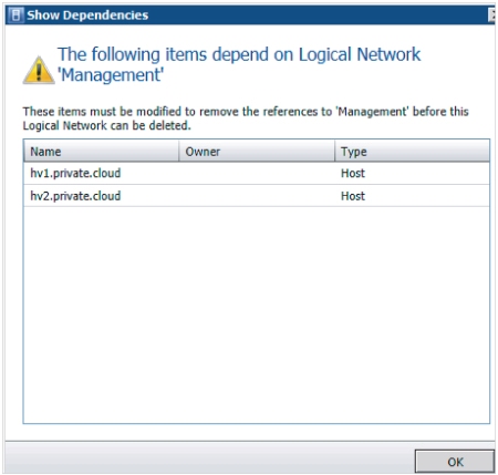
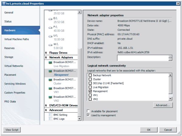
Figure 6.7 shows how a host network adapter is connected to a Logical Network in the properties of the Hyper-V servers. Right-click the identified servers one by one, select Properties → Hardware, and move down to Network Adapters. If you click on the adapter connected to the Logical Network, you can deselect the logical networks associated with this adapter.
Figure 6.7 Connecting a host network adapter
When all the dependencies are removed, you can finally delete the logical networks by right-clicking it, and clicking Remove and Yes to confirm the deletion.
Creating IP Address Pools
In VMM you can create static IP address pools, which make it easy to allocate IP addresses to both hosts and VMs. In fact, all supported hypervisors (Hyper-V, VMware ESX, and XenServer) can benefit from this functionality. By assigning one or several subnets to your logical network definition, you can create an IP address pool for each subnet, including all relevant details such as network sites, relevant host groups, Virtual IP (VIP) addresses, reserved addresses, gateways, DNS servers, and WINS servers (at least if you still use the NetBIOS-based-name resolution method). You can create an IP address pool scoped to a host group with only a name and an IP range.
Once you have created a Logical Network and one or more sites, you can add an IP address pool and specify which network site and IP subnet it belongs to.
To create an IP address pool, follow these steps:
Figure 6.8 Adding a site with an IP subnet and VLAN

Figure 6.9 Logical Network with several IP pools

Viewing Assigned IP Addresses
Currently, the VMM graphical user interface offers no way to see which IP addresses have been assigned to which hosts or VMs. However, you can use PowerShell to view them.
To display a list of assigned IP address for a specific subnet, issue the following code:
PS C:> $IPAddressPool = Get-SCStaticIPAddressPool -IPv4 -Subnet "192.168.1.0/24"
PS C:> $IPAddressPool

Name                     : IP_Pool_Amsterdam
Description              :
AddressFamily            : InterNetwork
IPAddressRangeStart      : 192.168.1.1
IPAddressRangeEnd        : 192.168.1.254
AvailableDIPAddresses    : 71
AvailableAddresses       : 80
TotalDIPAddresses        : 74
TotalAddresses           : 83
UnassignedAddresses      : 0
UnassignedDIPAddresses   : 0
UnassignedVIPAddresses   : 0
AvailableVIPAddresses    : 9
TotalVIPAddresses        : 9
DNSSearchSuffixes        : {}
DNSSuffix                : private.cloud
DNSServers               : {192.168.1.21, 192.168.1.22}
DefaultGateways          : {192.168.1.1}
WINSServers              : {}
EnableNetBIOS            : False
IPAddressReservedSet     : 192.168.1.11-192.168.1.180
ReservedAddresses        : 171
VIPAddressSet            : 192.168.1.2-192.168.1.10
Subnet                   : 192.168.1.0/24
IsIPv4                   : True
LogicalNetworkDefinition : Site_Amsterdam
ServerConnection         : Microsoft.SystemCenter.VirtualMachineManager.Remoting.ServerConnection
ID                       : f8322ffa-636f-464f-b2ff-6af7f943ed6a
IsViewOnly               : False
ObjectType               : StaticIPAddressPool
MarkedForDeletion        : False
IsFullyCached            : True

PS C:> $IPAddress = Get-SCIPAddress -StaticIPAddressPool $IPAddressPool
-Assigned
PS C:> $IPAddress

Name                  : 192.168.1.181
Address               : 192.168.1.181
AllocatingAddressPool : IP_Pool_Amsterdam
AssignedToID          : e4008576-4742-4f57-94b5-e6f4d7de3e7c
AssignedToType        : VirtualNetworkAdapter
Type                  : DedicatedIP
State                 : Assigned
Description           : DC3
ServerConnection      : Microsoft.SystemCenter.VirtualMachineManager.Remoting.ServerConnection
ID                    : 392d44d6-2378-4599-9742-6bca85adc715
IsViewOnly            : False
ObjectType            : AllocatedIPAddress
MarkedForDeletion     : False
IsFullyCached         : True
-Assigned
PS C:> $IPAddress
Name : 192.168.1.181
Address : 192.168.1.181
AllocatingAddressPool : IP_Pool_Amsterdam
AssignedToID : e4008576-4742-4f57-94b5-e6f4d7de3e7c
AssignedToType : VirtualNetworkAdapter
Type : DedicatedIP
State : Assigned
Description : DC3
ServerConnection : Microsoft.SystemCenter.VirtualMachineManager.Remoting.ServerConnection
ID : 392d44d6-2378-4599-9742-6bca85adc715
IsViewOnly : False
ObjectType : AllocatedIPAddress
MarkedForDeletion : False
IsFullyCached : True
All assigned addresses are currently saved in an array and can be individually addressed by their position in the array.
PS C:> $IPAddress[1]

Name                  : 192.168.1.202
Address               : 192.168.1.202
AllocatingAddressPool : IP_Pool_Amsterdam
AssignedToID          : f45a659b-e7d2-42a4-a917-cb369e95f710
AssignedToType        : VirtualMachine
Type                  : DedicatedIP
State                 : Assigned
Description           : HVS-SSQL04
ServerConnection      : Microsoft.SystemCenter.VirtualMachineManager.Remoting.ServerConnection
ID                    : f3c893b3-8c8b-47ae-a042-1c63526395bb
IsViewOnly            : False
ObjectType            : AllocatedIPAddress
MarkedForDeletion     : False
IsFullyCached         : True

PS C:> $IPAddress[2]

Name                  : 192.168.1.207
Address               : 192.168.1.207
AllocatingAddressPool : IP_Pool_Amsterdam
AssignedToID          : db155230-c74e-4d85-ba00-7a214325d9d8
AssignedToType        : VirtualMachine
Type                  : DedicatedIP
State                 : Assigned
Description           : TEST01
ServerConnection      : Microsoft.SystemCenter.VirtualMachineManager.Remoting.ServerConnection
ID                    : 09baba92-2e4e-4ebc-8ddd-827015e8b8be
IsViewOnly            : False
ObjectType            : AllocatedIPAddress
MarkedForDeletion     : False
IsFullyCached         : True
If you want to unassign an entry from the IP pool, use this command:
PS C:> $IPAddress[2] | Revoke-SCIPAddress

Name                  : 192.168.1.207
Address               : 192.168.1.207
AllocatingAddressPool : IP_Pool_Amsterdam
AssignedToID          : db155230-c74e-4d85-ba00-7a214325d9d8
AssignedToType        : VirtualMachine
Type                  : DedicatedIP
State                 : Assigned
Description           : TEST02
ServerConnection      : Microsoft.SystemCenter.VirtualMachineManager.Remoting.ServerConnection
ID                    : 09baba92-2e4e-4ebc-8ddd-827015e8b8be
IsViewOnly            : False
ObjectType            : AllocatedIPAddress
MarkedForDeletion     : True
IsFullyCached         : True
The available number of addresses increases from 71 to 72:
PS C:> $IPAddressPool.AvailableDIPAddresses
72
As you can see in Figure 6.10, shortly after the IP address is revoked, a job is run to delete the IP addresses marked for deletion.
Figure 6.10 Returning IP addresses to the pool

PS C:> $IPAddress = Get-SCIPAddress -StaticIPAddressPool $IPAddressPool
-Assigned
PS C:> $IPAddress

Name                  : 192.168.1.181
Address               : 192.168.1.181
AllocatingAddressPool : IP_Pool_Amsterdam
AssignedToID          : e4008576-4742-4f57-94b5-e6f4d7de3e7c
AssignedToType        : VirtualNetworkAdapter
Type                  : DedicatedIP
State                 : Assigned
Description           : DC3
ServerConnection      : Microsoft.SystemCenter.VirtualMachineManager.Remoting.ServerConnection
ID                    : 392d44d6-2378-4599-9742-6bca85adc715
IsViewOnly            : False
ObjectType            : AllocatedIPAddress
MarkedForDeletion     : False
IsFullyCached         : True

Name                  : 192.168.1.202
Address               : 192.168.1.202
AllocatingAddressPool : IP_Pool_Amsterdam
AssignedToID          : f45a659b-e7d2-42a4-a917-cb369e95f710
AssignedToType        : VirtualMachine
Type                  : DedicatedIP
State                 : Assigned
Description           : TEST01
ServerConnection      : Microsoft.SystemCenter.VirtualMachineManager.Remoting.ServerConnection
ID                    : f3c893b3-8c8b-47ae-a042-1c63526395bb
IsViewOnly            : False
ObjectType            : AllocatedIPAddress
MarkedForDeletion     : False
IsFullyCached         : True
This PowerShell command lists all statically assigned IP addresses:
PS C:> Get-SCIPAddress | ft address, AllocatingAddressPool, Description, Type,
State -auto

Address       AllocatingAddressPool    Description          Type         State
-------       ---------------------    -----------          ---          -----
10.0.1.51     IPv4_Pool_Live_Migration hv1.private.cloud    DedicatedIP  Assigned
192.168.1.202 IP_Pool_Amsterdam        TEST01               DedicatedIP  Assigned
192.168.2.202 IP_Pool_Dublin           TEST01               DedicatedIP  Assigned
192.168.1.181 IP_Pool_Amsterdam        DC3                  DedicatedIP  Assigned
192.168.2.203 IP_Pool_Dublin           TEST02               DedicatedIP  Assigned
10.0.1.52     IPv4_Pool_Live_Migration hv2.private.cloud    DedicatedIP  Assigned
192.168.2.182 IP_Pool_Dublin           DC3                  DedicatedIP  Assigned
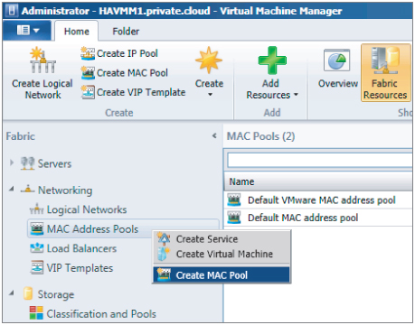
Creating a MAC Address Pool
When you install VMM, two default Media Access Control (MAC) address pools use two different ranges. (If you don't need to create custom MAC address pools, you can skip this section.) There is one default pool for both Hyper-V and Citrix XenServer hypervisors and one default pool for VMware ESX hypervisor, as listed in Table 6.1.
Table 6.1 MAC Addresses
| MAC Address Pool Name | Hypervisor | MAC Address Range |
| Default MAC address pool | Hyper-VCitrix XenServer | 00:1D:D8:B7:1C:00 – 00:1D:D8:F4:1F:FF |
| Default VMware MAC address pool | VMware ESX | 00:50:56:00:00:00 – 00:50:56:3F:FF:FF |
If you need to create one or more custom MAC address pools, follow these steps:
Figure 6.11 Creating a MAC pool
Releasing Inactive IP or MAC Addresses
Under certain conditions, IP or MAC addresses can become inactive. This happens when a host was assigned a static IP address during a bare-metal deployment job and is subsequently removed from VMM management. When removing the host, VMM marks all statically assigned IP and MAC addresses as inactive.
A second example is when a VM goes into a missing state. This can happen if the VM was removed outside VMM. Inactive IP addresses can be removed using the following steps:
Similarly, MAC addresses can be removed with these steps:
Adding and Configuring Load Balancers and VIP Templates
Load balancers are physical or virtual devices that are used to distribute service requests to resources in the private cloud. A load balancer is typically used to configure access to applications with fair access, high availability, and scalability in mind. HTTP, HTTPS, and FTP are typical services that are suitable for load balancing because they require dynamic path selection or some sort of failover mechanism if one of the devices happens to fail. Configuration of such load-balancing hardware or its virtualized appliance version is naturally the domain of the network admin.
Configuring and maintaining a private cloud becomes a lot easier when virtualized networks are manageable entities in the VMM fabric. This is true when subnet and VLAN pairs are represented as logical networks in VMM. It is also beneficial when applications and (web) services are automatically referred to a load balancer with an optimal configuration for the specific workload. After all, one of the key differences between a classic data center and a private cloud is that cloud-service management is automated, and therefore repeatable, predictable, and easy to maintain.
Along with the concepts of Logical Networks and IP/MAC pools, VMM introduces two other network abstractions: load balancers and VIP templates. After Logical Networks have been created by the fabric admin, Self-Service users can easily utilize the load-balancing configuration if all they have to do is select the most appropriate template for the applications they are deploying. During deployment and reconfiguration of the service, no administrator intervention is required.
You might be familiar with the tedious and complex process of defining a load-balancer configuration for a specific application and bringing that configuration into production. It takes considerable effort for the server, application, and network admins to get this job done. Much of the work involved needs to be repeated if configurations are changed. It takes precious time and involves risk to take an application out of the load balancer, change the configuration, and put it back again.
As you saw earlier, you can reserve an IP range for load balancers in an IP address pool that is attached to a Logical Network. A VIP address pool follows the same pattern as an IP address pool. When a VIP is given to a load balancer, it is checked out from the IP pool.
When you are doing load-balancer integration and leveraging VMM to configure the load balancer, VMM not only adds the machine into the right pool during application deployment; it is also smart enough to pull machines out of the pool based on the characteristics a template author has defined, do the upgrade on a particular machine, add it back, and re-enable the pool. So, it is not just the initial configuration of the VIP that VMM takes care of; it also handles the initial setup of the VMs that are placed behind that VIP. VMM also handles the ongoing management and maintenance, ensuring that application users don't experience any downtime.
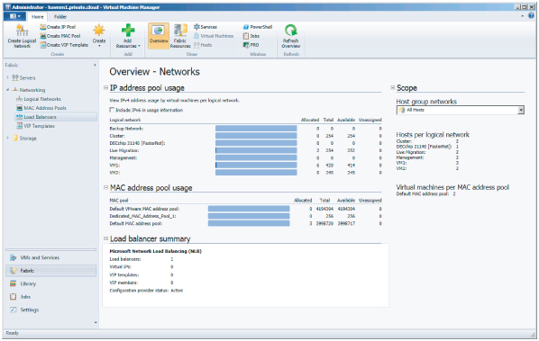
To get a good overview of the networks you have created so far, go to the Networking workspace and click Overview (Figure 6.12) on the ribbon.
Figure 6.12 Overview of networks
Out of the box VMM comes with one load-balancer configuration provider installed: Microsoft's software-based network load-balancing (NLB) solution, which is an integral part of all current Windows Server editions. Before you add any other load balancers, check to see if a piece of software called a load-balancer provider is available for your specific manufacturer and model. Currently, providers are available for Citrix NetScaler VPX, Brocade ADX, and BigIP F5. Several vendors offer a VM-based version of their load-balancer product, which makes it convenient to integrate into your VMM environment.
Installing the Load-Balancer Provider
First, you need to download the latest version of the load-balancer provider offered by the load-balancer vendor. These are the currently known vendors' sites that offer load-balancer providers:
Citrix NetScaler VPX:
www.citrix.com/English/ps2/products/feature.asp?contentID=2300361&ntref=bottompromo_ns
Brocade ADX:
BIG-IP F5:
A load-balancer provider is written in PowerShell, and if no other provider is available for your specific load-balancer hardware, you can always write your own provider.
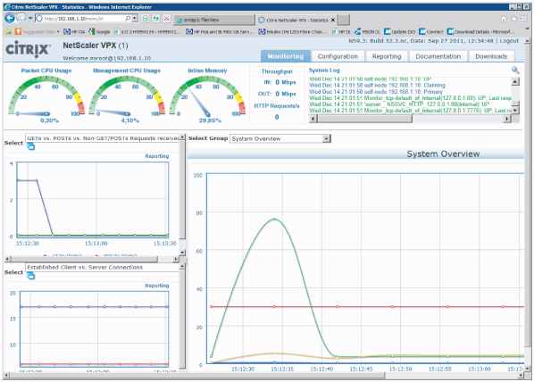
If you do not have a hardware load balancer at hand, you might want to try Citrix NetScaler (Figure 6.13), which is available as a VM that runs on Hyper-V. It simulates a hardware load balancer and is great for testing purposes. You can download it from My Citrix:
www.citrix.com/lang/english/publicindex.asp?destURL=/English/myCitrix/index.asp&ntref=Try
Figure 6.13 The Citrix NetScaler load balancer
Before you can actually see a load balancer in VMM, you need to install a piece of software called the load-balancer provider and then restart the VMM service. Another step you must complete is to add a Run As account specifically for the load balancer.
During setup, you can run a number of tests to validate the existence and connection with the load balancer. After you install the load-balancer provider, the VMM service must be restarted. If you run a highly available (HA) VMM server, you can perform a failover of the VMM management server between the nodes in the cluster.
Installing a Citrix NetScaler Load Balancer Provider
To install a Citrix NetScaler load balancer provider, complete the following steps:
To add the provider, follow these steps:
Figure 6.14 Adding a load-balancer provider

Figure 6.15 Specifying the logical network affinity
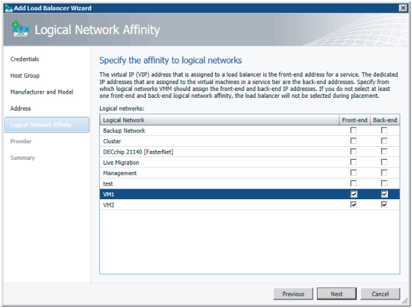
Figure 6.16 Testing the load balancer

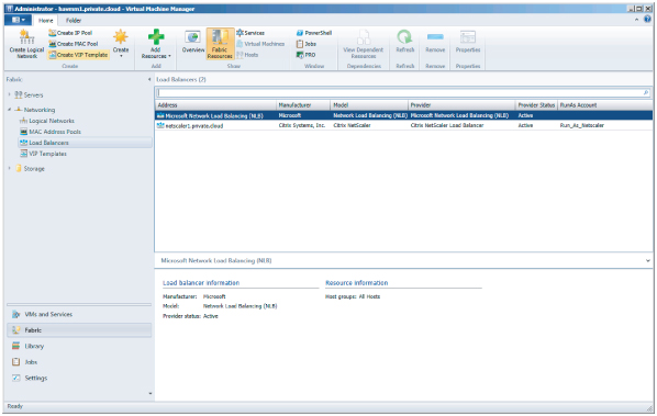
Both the Microsoft and the Citrix network load balancers should appear under Fabric Resources in the Detail pane, as shown in Figure 6.17.
Figure 6.17 List of load balancers
Installing a BIG-IP F5 Load-Balancer Provider
To install a BIG-IP F5 load-balancer provider, complete the following steps:
If you have access to an F5 hardware load balancer, you can add it using the same procedure used for the NetScaler, including the setup of a Run As account for F5.
Defining a VIP Template
A VIP template is a collection of load-balancer configuration settings that are optimized for the expected network traffic for a specific application or service offered in a private cloud. In fact, a VIP template represents a combination of the vendor's best practices, the network admin's expertise, and the requirements of application admins for that service.
Because they represent different application requirements, it is quite common to have multiple VIP templates per load balancer. Each VIP template is configured with the following settings:
- Template name
- Template description
- Virtual IP port
- Template type
- Generic if intended for all load balancers
- Specific if intended for a load balancer specific to a manufacturer and model
- Protocol
- HTTP
- HTTPS passthrough
- HTTPS terminate
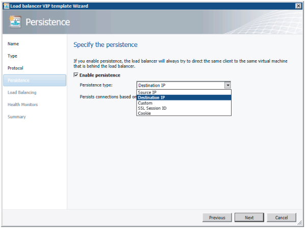
- Persistence type
- Source IP
- Destination IP
- SSL Session ID
- Cookie
- Custom
- Load balancing methods
- Least connections
- Fastest response time
- Round robin
- Health monitors
- Configurable (You can specify protocol, response, interval, timeout, and retries for a request—for example, Get.)
You can define a generic VIP template before adding any load-balancer providers. A generic VIP template is a load-balancer configuration that applies to all load balancers. Of course, if you want to create a specific VIP template, you need to install the specific load-balancer provider with its specific models and methods.
The following procedure creates a VIP template for applications that need load balancing on port 443 using HTTPS:
Figure 6.18 Specifying persistence
Now that you have created a VIP template, you can apply it to one of the service templates in the Service Template Designer (Figure 6.19).
Figure 6.19 Using a VIP Template in the Service Template Designer

The Self-Service user only has to choose the desired VIP template while deploying a service instance. VMM then uses the correct load-balancer provider and related load-balancer device found within the scope of the host group. It configures the load balancer, creates the VIP, brings up the VMs, attaches them to the proper pool, and enables the VMs used in the service template for load balancing.
Preparing Storage Integration and Automation
Storage is the second of the three major building blocks that make up the private-cloud fabric. In this section, you will learn how to integrate storage arrays from multiple vendors into VMM. After all, when you build a cluster of virtualization hosts, some kind of shared storage will always be part of the solution, whether it is based on iSCSI, fibre channel, or shared SAS. Both hardware- and software-based storage solutions require configuration before your hosts can be clustered.
The biggest storage-related challenge with previous versions of VMM is the lack of visibility beyond the disks and virtual hard disks (VHDs) that Windows and Hyper-V can see. Another challenge is that admins require different tools and consoles to configure storage for their virtualization hosts and clusters.
One way to confront these challenges is to utilize a management standard that looks beyond the products of a single storage vendor. However, if you base your private cloud on VMM 2012, the product should not be built around a proprietary storage stack, nor should it replace the vendor's storage resource–management tools. Given the variety of storage vendors and storage products, Microsoft looked for an industry standard, which they found in SMI-S.
Deep Storage Integration with SMI-S
SMI-S was developed under the auspices of the Storage Networking Industry Association (SNIA) and has been ratified by ANSI. SMI-S defines a method for the interoperable management of a heterogeneous storage-area network (SAN), and describes the information available to a web-based enterprise management (WBEM) client from an SMI-S–compliant common information model (CIM) server and an object-oriented and XML-messaging-based interface to support the specific requirements of managing devices in a SAN.
Although SMI-S v1.0 became an ISO/IEC standard in 2007, many storage vendors continued their own proprietary methods for operating their storage devices. Only a minority of leading storage vendors provided limited support for SMI-S in their devices. This proved to be challenge for Microsoft's intention to apply SMI-S as its standard protocol to communicate with storage devices and fully integrate storage into VMM. Microsoft requests a minimum of the SMI-S provider of version 1.4. On the SNIA web page, you can verify what devices have been tested against this SMI-S version.
At first, SMI-S provided only for identification of the attributes and properties of storage devices. The current version also delivers full discovery and automated configuration of storage devices. For VMM this means you get not only full end-to-end visibility all the way from the VHD to the array controller, but also full configuration of a logical unit (LUN)— provisioning it to a host, partitioning, formatting, and finally using it. Rapid deployment technology for both the physical host and the VM are made possible by this kind of deep storage integration in VMM.
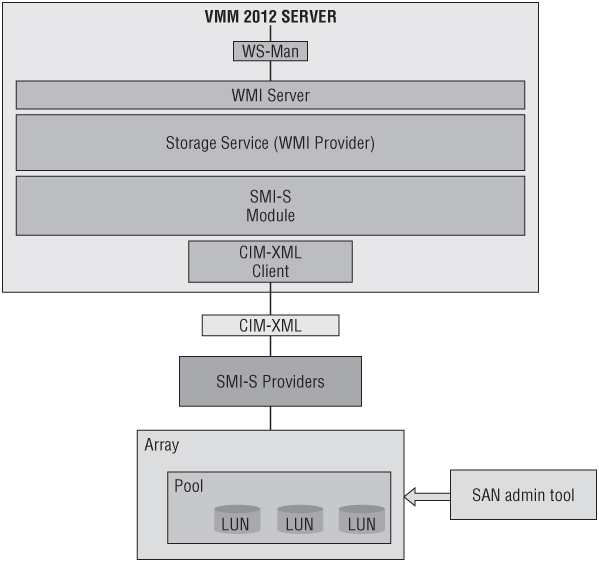
Figure 6.20 depicts the different components in the storage stack that VMM uses based on a combination of WS-Management, WMI, SMI-S, and CIM-XML.
Figure 6.20 The VMM storage stack
Storage integration in VMM offers the following features:
Discovery
Remote storage is often invisible to non-storage administrators. An important feature, therefore, is being able to discover not only local storage but also shared storage arrays with its storage groups (pools), logical units (LUNs), disks, volumes, and virtual disks.
Resource Mapping
When VMM has discovered all the different storage parts, a VM can be mapped to these specific storage parts. In other words, you can create a full end-to-end map in the VMM console and in PowerShell. Since this overview is dynamic, there is no need to use a spreadsheet to document the storage used by hosts and VMs.
Classification
Your private cloud will have consumers that are unaware of the technical specifications of storage and how they can be used appropriately. Therefore, an easy-to-understand classification model can help the Self-Service user when deploying a VM or a service.
Allocation
Local storage is directly connected to a virtualization host and, therefore, need not be allocated. This is different for shared storage (also referred to as network storage or SAN-based storage). After the VMM service has become aware of this shared storage, it can be allocated to one or more host groups before it can be assigned to a host. Since allocation is a different step from assignment, VMM allows the administrator to allocate storage to a business unit without assigning it to a specific virtualization host or VM.
Assignment
After storage has been allocated to a host group or cloud, private cloud consumers—which can be application owners or administrators—simply look up what storage classifications and capacity is allocated to them and assign it to a Hyper-V host. In traditional IT environments, the process of storage presentation or unmasking is normally done by the storage administrator. In VMM with deep storage integration, assigning storage to a host is fully automated, including the presentation/unmasking part. If the storage is assigned to a Hyper-V cluster, VMM will also create the cluster resources and make them shared across the cluster.
Provisioning
In the previous section, you were dealing with existing storage that was ready to be assigned as new LUNs to a host or cluster. When there is enough capacity available, you might also want to create one or more LUNs and provision them to a host or cluster. There are several ways of provisioning a LUN:
- Create new LUN from available storage.
- Create a (writeable) snapshot of an existing LUN.
- Create a clone of an existing LUN.
Features like snapshotting and cloning often depend on the capabilities of your storage array and are often available as options with additional licenses. Creating a LUN and provisioning it to a host or cluster is basic functionality for all storage arrays.
Decommissioning
When you stop using a host, a VM, or a service, you might want to give back some of the storage to the pool. This process of decommissioning can also be performed by VMM, both via the GUI and via PowerShell.
Storage Classifications
Simplification and abstraction are also relevant to storage. Shared storage arrays are usually considered to be black boxes for everyone but the storage admin. This is why VMM also introduces a simplified model of storage to end users who are creating VMs in a private cloud. In VMM, storage can be classified using a friendly descriptive name.
The storage admin who knows the capabilities of the storage array can create different labels for these different capabilities. They could be as simple as Gold, Silver, and Bronze; but HighIO, MediumIO, and LowIO are descriptive enough (although the latter could easily be too technical for private-cloud consumers). Another example could be HighAvailableStorage and MediumAvailableStorage (LowAvailableStorage would probably be too discouraging to be a serious alternative)—of course, all with the intention to put different price tags to the labels. A self-service user would understand to select Gold, HighIO, and HighAvailableStorage for important enterprise workloads and Bronze, LowIO, and MediumAvailableStorage for testing purposes only.
You can create storage classifications without adding storage arrays to the VMM fabric. Of course, they will not be of much use until a supported array is integrated.
To create Storage Classifications, follow these steps:
This is the PowerShell alternative for creating several storage classifications:
PS C:> New-SCStorageClassification -Name "Gold" -Description "Enterprise storage
storage (SATA, 7.2K, dual-ported, RAID5)" -RunAsynchronously
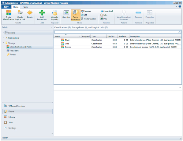
When you've finished creating the classifications, you should see something like Figure 6.21. All of the classifications have zero capacity, because no storage arrays have been discovered and integrated into VMM. For the same reason, the number of storage pools is zero.
Figure 6.21 Storage classifications
During the discovery of a storage array, you can also create new classifications, as you will see in the next paragraphs.
Discovering Storage Arrays
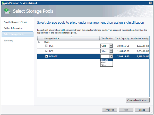
Your next step is to discover one or more storage arrays. To do that, follow these steps:
Figure 6.22 Specifying the discovery scope

Figure 6.23 Assigning classifications to the storage pools
PS C:> $array = Get-SCStorageArray -Name "HSV1" | where { $_.ID -eq
"11514140-4997-4893-a243-10ce2ceb3bb5" }
PS C:> $pools = @()
PS C:> $pools += Get-SCStoragePool -Name "DG2" | where { $_.ID -eq "81a0bb38-
e0e2-4dc4- 9ce1-93eba03f8ab3" }
PS C:> $pools += Get-SCStoragePool -Name "DGFATA1" | where { $_.ID -eq
"7915c87c-0c5a- 4871-b6e2-f572cc621bef" }
PS C:> $pools += Get-SCStoragePool -Name "DG1" | where { $_.ID -eq "0258c221-
e09f-47c3- 9d49-060d48a593f3" }
PS C:> $classifications = @()
PS C:> $classifications += Get-SCStorageClassification -Name "Silver"
PS C:> $classifications += Get-SCStorageClassification -Name "Bronze"
PS C:> $classifications += Get-SCStorageClassification -Name "Gold"
PS C:> Set-SCStorageArray -StorageArray $array -AddStoragePoolToManagement
$pools - StorageClassificationAssociation $classifications -RunAsynchronously
You can find the array in PowerShell by using the following commands:
PS C:> $arr=Get-SCStorageArray
PS C:> $arr

ObjectId                         : root/eva:sHPSMS2.PRIVATE.CLOUD:5989;HPEVA_StorageSystem.CreationClassName=%‘HPEVA_StorageSystem%’,Name=%‘50001FE15003E8C0%’
SMDisplayName                    : HSV1
SMName                           : 50001FE15003E8C0
SMNameFormat                     : WWN
ManagementServer                 : HTTPS://HPSMS2.PRIVATE.CLOUD:5989
HardwareIDFlags                  : SupportsPortWWN
MaskingFlags                     : SupportsMasking
ReplicationFlags                 : SupportsMirrorLocal, SupportsSnapshotLocal, SupportsCloneLocal
ConfigurationFlags               : SupportsStorageLogicalUnitCreation, SupportsStorageLogicalUnitDeletion, SupportsStorageLogicalUnitModification, SupportsStorageLogicalUnitCapacityExpansion, SupportsStorageLogicalUnitCapacityReduction
MaskingMaximumMapCount           : 0
MaximumReplicasPerSourceClone    : 1
MaximumReplicasPerSourceMirror   : 0
MaximumReplicasPerSourceSnapshot : 7
MaskingOneHardwareIDPerView      : False
MaskingPortsPerView              : AllPortsShareTheSameView
FirmwareVersion                  :
Manufacturer                     : Hewlett-Packard
Model                            : HSV100
SerialNumber                     : P66C5E2AAQV01G, P66C5E2AAQU00U
Tag                              : 50001FE15003E8C0
LogicalUnitCopyMethod            : Snapshot
StorageProvider                  : hpsms2.private.cloud:5989
StoragePools                     : {DG1, DG2, DGFATA1}
StorageEndpoints                 : {50001FE15003E8C0.P66C5E2AAQU00U.hostport1, 50001FE15003E8C0.P66C5E2AAQV01G.hostport1, 50001FE15003E8C0.P66C5E2AAQU00U.hostport2, 50001FE15003E8C0.P66C5E2AAQV01G.hostport2}
StorageInitiators                : {210000E08B826931, 50060B0000C2621C, 50060B0000C2621A, 210100E08BB27058…}
StorageiSCSIPortals              : {}
StorageGroups                    : {01800710B40805603A2510000080000000005401, 03800710B40805603A2510000080000000009401, 02800710B40805603A251000008000000000B001,  0C800710B40805603A2510000080000000005601}
TotalCapacity                    : 7380428851772
RemainingCapacity                : 5337839042558
InUseCapacity                    : 2042589809214
IsCloneCapable                   : True
IsSnapshotCapable                : True
IsSanTransferCapable             : True
CreateStorageGroupsPerCluster    : False
TotalAllocatedCapacity           : 1327144894464
ObjectType                       : StorageArray
Accessibility                    : Public
Name                             : HSV1
IsViewOnly                       : False
Description                      : HSV1
AddedTime                        : 12/28/2011 2:00:10 PM
ModifiedTime                     : 12/28/2011 2:16:39 PM
Enabled                          : True
MostRecentTask                   :
ServerConnection                 : Microsoft.SystemCenter.VirtualMachineManager.Remoting.ServerConnection
ID                               : 11514140-4997-4893-a243-10ce2ceb3bb5
MarkedForDeletion                : False
IsFullyCached                    : False
As you can see, a lot of information about the storage array is available, including its manufacturer ($arr.Manufacturer), name ($arr.Name), model ($arr.Model), management server ($arr.ManagementServer), supported functions ($arr.ConfigurationFlags), storage pools ($arr.StoragePools), total capacity ($arr.TotalCapacity), and remaining capacity ($arr.RemainingCapacity).
To demonstrate how storage from multiple storage arrays can be used in a standardized way, let's add another storage device.
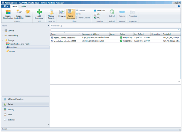
In Figure 6.24, a list of storage providers specifies the name, management address, status, last refresh time, and credentials used for each device. To view this list, select Fabric, expand Storage, and select Providers while viewing the Fabric Resources.
Figure 6.24 List of storage providers
You can view managed storage arrays in the same view by clicking Arrays. The Information pane lists the arrays with their name, total capacity, used capacity, pools, provider name, and status. If you select an array in the list, more information about it (such as the number of LUNs provisioned, assigned and unassigned) appears at the bottom of the screen (Figure 6.25).
Figure 6.25 Viewing the array details

In the ribbon, switch the view from Fabric Resources to Overview to obtain a storage overview with details about used, total, and available storage—including classification use and LUNs per array, as shown in Figure 6.26.
Figure 6.26 Overview of storage use

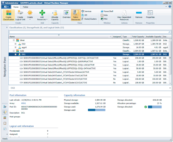
From this overview, you can access shortcuts to classifications and arrays. If you click the Gold classification, for instance, you'll get a detailed view of the storage groups and LUNs classified as Gold (Figure 6.27). To get a better view, you can collapse the Navigation pane by pressing the left-arrow button (←). If you type the name of your pool or LUN, you will see only those logical units.
Figure 6.27 Viewing storage by classification
Creating Logical Units
You can choose to first create one or more LUNs and then allocate storage capacity to a host group or vice versa. You can also leave the creation of LUNs in the hands of the storage admin and allocate only the provisioned storage capacity to host groups. Storage capacity is also assigned to the cloud via the host group.
To create a logical unit, follow these steps:
Removing Logical Units
While a logical unit is still unassigned, you can remove the LUN via the following the steps:
Figure 6.28 Removing a logical unit

Allocating Storage Pools and Logical Units
After your arrays have been discovered, your storage pools have been classified, and one or more logical units have been created, you are ready to allocate those storage pools and logical units to host groups. Only after these steps can you make disks available to Hyper-V hosts and clusters. To do that, follow these steps:
Figure 6.29 Selecting a host group for storage allocation

Figure 6.30 Allocating the storage pools

Figure 6.31 Adding logical units

Assigning Storage on a Hyper-V Host
Before you can assign a logical unit to a Hyper-V host, certain prerequisites must be met. Consider the following:
- One or more storage arrays should be discovered and classified in VMM.
- One or more logical units should be created in VMM, or outside of VMM with the storage vendor's storage-management tool.
- One or more storage pools and logical units should be allocated to the host group that contains the Hyper-V host.
- Multi-Path IO (MPIO) should be configured on the Hyper-V host and, if available, the vendor-specific device-specific module (DSM) must be installed.
- If you are using a Fibre Channel SAN, the Hyper-V host must have connectivity to the array (zoning).
- If you are using an iSCSI SAN, there should be a configured iSCSI portal on the Hyper-V host. The iSCSI Initiator service should be started and set to Automatic.
Configuring a Single Storage Group for a Hyper-V Cluster
VMM creates one storage group per host and one storage group per cluster node. A storage group can contain one or more of the host's initiator IDs. For iSCSI these are called iSCSI Qualified Name (IQN), and for Fibre Channel these are the World Wide Name (WWN).
For certain storage arrays, only one storage group is preferred for the entire cluster so that all host initiators for all nodes are placed in the same storage group. A single storage group is defined as an object binding multiple related host initiators, target ports, and logical units. In fact, the target ports are used to expose logical units to the host initiators. To configure a single storage group, start a PowerShell screen and enter the following command to find the current state, which should be False by default.
PS C:> $arr = Get-SCStorageArray | where {$_.SMDisplayname -like "ontap1" }
PS C:> $arr.CreateStorageGroupsPerCluster
False
To set the value for CreateStorageGroupsPerCluster to True, enter the following PowerShell command:
PS C:> Set-SCStorageArray -StorageArray $arr -CreateStorageGroupsPerCluster $true
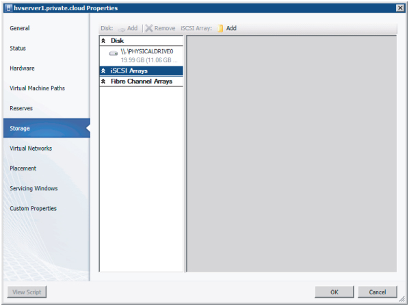
Adding an iSCSI Array to a Hyper-V host
Before you can assign logical disks to a Hyper-V host via iSCSI, you need to configure the iSCSI array in the Storage properties of a Hyper-V host. The Hyper-V host should have its iSCSI portals configured.
Figure 6.32 Adding an iSCSI array
The resulting PowerShell script looks like this:
PS C:> $vmHost = Get-SCVMHost -ComputerName "hvserver1" | where { $_.ID -eq
"b778f655- b014-4a6c-9451-429a3b848f41" }
PS C:> $iSCSIHba = $vmHost.InternetSCSIHbas | where { $_.ID -eq "9aa491c2-cdcd-
40a3- b590-4c08de6e7817" }
PS C:> $array = Get-SCStorageArray -Name "ontap1" | where { $_.ID -eq "8f5a9a4a-
e3a3- 413f-bb14-a3f45e0a9967" }
PS C:> $targetPortal = $array.StorageiSCSIPortals | where { $_.ID -eq "24871c45-
9def- 4dbe-b6a9-63f453397dd9" -and $_.IPv4Address -eq "172.16.1.10" }
PS C:> $selectedEndPoint = $targetPortal.StorageEndpoints | where { $_.ID -eq
"434a5ac3- 7337-4a77-b28a-a75153ad1456" -and $_.Name -eq "iqn.1992-08.com.netapp:sn.99927627,t,0x03E8" }
PS C:> Set-InternetSCSIHba -InternetSCSIHba $iSCSIHba -TargetPortal
$targetPortal - TargetName $selectedEndPoint -CreateSession -InitiatorIP "172.16.1.53"
When you open the Storage tab on the Hyper-V host's properties again, you will see that an iSCSI session has been created and the configured iSCSI array can be found under iSCSI Arrays, as shown in Figure 6.33.
Figure 6.33 Establishing a session with an iSCSI array

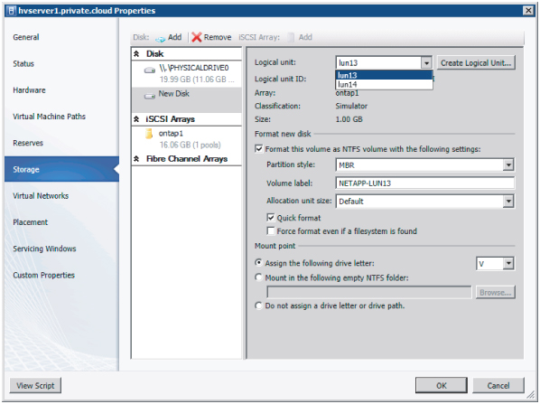
Adding a Disk from an iSCSI Array to a Hyper-V Host
Now that the Hyper-V host can see the iSCSI storage array, you can add one or more disks using the Add button, which is now available.
To add an existing disk, follow these steps:
Figure 6.34 Adding a disk
The resulting PowerShell script looks like this:
PS C:> $vmHost = Get-SCVMHost -ID "b778f655-b014-4a6c-9451-429a3b848f41"
$vmHost - JobGroup "17a2e45d-dc96-4fbb-aeea-f5414f748f0a" PS C:> $lun = Get-SCStorageLogicalUnit -ID "b0af0c9c-703d-4bcd-9f39-
To see if the task completed successfully, click Jobs in the Workspace pane.
You can also go back to the Storage tab in the properties of the Hyper-V host to see if the new logical disk has been added, partitioned, formatted, labeled, and mounted (Figure 6.35).
Figure 6.35 Checking for job completion

End-to-End Storage Mapping
VMM uses SMI-S as a storage standard to add supported storage arrays and extend your view of storage in VMM, all the way from the VM to the storage array. The best way to see this in action is to use PowerShell to get all the intermediate steps between the VHD of a VM to the logical disk on a storage array.
First, take a look at the properties of the VMM server, assuming you are already connected.
# SELECT VMM CLUSTERNAME
PS C:> $vmmserver = Get-VMMserver "havmm1.private.cloud"

# DISPLAY PROPERTIES OF SELECTED VMM SERVER
PS C:> $vmmserver
Name                                   : havmm1.private.cloud
Port                                   : 8100
IsConnected                            : True
ServerInterfaceVersion                 : 2.1.0
Profile                                : Administrator
UserRole                               : Administrator
UserRoleId                             : 75700cd5-893e-4f68-ada7-50ef4668acc6
FullyQualifiedDomainName               : havmm1.private.cloud
FQDN                                   : havmm1.private.cloud
[shortened]
Next, focus on a particular VM called dc3.private.cloud. To find everything that is related to storage, run this code:
# GET VIRTUAL MACHINE IN PRIVATE CLOUD WHERE NAME OF THE VM IS DC3
PS C:> $vm = Get-SCVirtualMachine | where {$_.Name -eq "dc3"}) | fl Name,
Location, VirtualMachineState, VirtualDiskDrives, VMHost

Name                : DC3
Location            : C:ClusterStorageVolume1DC3
VirtualMachineState : Running
VirtualDiskDrives   : {DC3}
VMHost              : hv1.private.cloud

# MAP FROM VIRTUAL MACHINE TO DISK DRIVE
PS C:> $vm.VirtualDiskDrives | fl VirtualHardDisk, BusType, Bus, LUN, ObjectType

VirtualHardDisk : W2K8R2SP1_v2_disk_1.vhd
BusType         : IDE
Bus             : 0
LUN             : 0
ObjectType : VirtualDiskDrive # MAP FROM VIRTUAL DISK DRIVE TO VIRTUAL HARD DISK PS C:> $vm.VirtualDiskDrives[0].VirtualHardDisk | fl Location, HostVolume, VMHost Location : C:ClusterStorageVolume1DC3W2K8R2SP1_v2_disk_1.vhd HostVolume : C:ClusterStorageVolume1 VMHost : hv1.private.cloud # MAP VIRTUAL HARD DISK TO HOST VOLUME PS C:> $vm.VirtualDiskDrives[0].VirtualHardDisk.HostVolume | fl MountPoints,
DeviceID, UniqueID, SMLunId, StorageLogicalUnit, VMHost

DeviceID           : \.PHYSICALDRIVE2
UniqueID           : 1824538386
SMLunId            : 600508B40010253A00008000026D0000
StorageLogicalUnit : 50001FE15003E8C0\Virtual DisksHVCluster1_FCHVCluster1CSV1ACTIVE
VMHost             : hv1.private.cloud

# MAP HOST DISK TO STORAGE LOGICAL UNIT
PS C:> $vm.VirtualDiskDrives[0].VirtualHardDisk.HostVolume.HostDisk.
StorageLogicalUnit | fl Name, CopyType, SourceLogicalUnit, StoragePool Name : 50001FE15003E8C0\Virtual DisksHVCluster1_FCHVCluster1CSV1ACTIVE CopyType : SourceLogicalUnit : StoragePool : DG1 # MAP STORAGE LOGICAL UNIT TO STORAGE POOL PS C:> $vm.VirtualDiskDrives[0].VirtualHardDisk.HostVolume.HostDisk.
StorageLogicalUnit. StoragePool.StorageArray.StorageProvider | fl Name, NetworkAddress, TCPPort, StorageArrays

Name           : hpsms2.private.cloud:5989
NetworkAddress : https://hpsms2.private.cloud
TCPPort        : 5989
StorageArrays  : {HSV1}
As you can see, integrating storage with SMI-S is very powerful and can give you a wealth of insight, all the way from the VHD in the VM to the array. Finally, virtual storage and physical storage don't have to be treated as distinct entities. End-to-end mapping will help you, as an administrator, troubleshoot issues that are related to the storage stack. The standardized approach of employing SMI-S will help you use identical procedures for storage arrays from different vendors. Provisioning storage to your private clouds with VMM can really help you in your job as a fabric administrator.
Storage Without SMI-S Support
Not all storage has SMI-S support. Does that mean this kind of storage has become useless? No, absolutely not! Local storage does not need SMI-S support because SMI-S is intended for network storage. Local storage is well understood by VMM out of the box.
If you have to deal with storage arrays without SMI-S support, you can still provision LUNs via the management tools offered by your SAN provider. SMI-S does not replace these tools but merely offers a standardized method of talking to a variety of storage arrays from different vendors. The procedure for managing storage with non–SMI-S-supported storage arrays is to create storage pools and LUNs outside VMM, present these LUNs to the servers (in the cluster), and let VMM do the rest. All VMM has to see is one or more raw disks. As soon as you have access to those disks, you can format the volume and convert them into CSVs in the case of Hyper-V clusters.
Of course, if you are looking for a new storage array or if you are replacing your existing storage array, SMI-S support with the minimum version that VMM expects (SMI-S v1.4 or higher) is highly recommended.
Summary
Networking and storage are two of the three important ingredients for building a fabric for your private clouds. If you administer one private cloud, you can dedicate all network and storage fabric components to that single cloud. If you host multiple clouds for different departments, subsidiaries, or external customers, the fabric is shared across multiple clouds. Fabric can be treated as a collection of devices that offer capacity that can grow and shrink as devices are added, removed, or replaced. The important part is that fabric in VMM 2012 is treated as a building block that is fully abstracted from the Self-Service user. The Self-Service user sees only meaningful names that represent physical devices and capacity. The fabric administrator has to take care of all the rest.
Networking and storage themselves can be considered as building blocks for servers or compute resources, as they are sometimes called. The next chapter shows how a heterogeneous set of virtualization hosts (Hyper-V, vSphere, and XenServer) can be integrated into a unified management platform for a private cloud that allows independent services (with applications) to run irrespective of the underlying fabric.