Chapter 2
Overview of Networking Components
Every network includes different components that connect them together. Although it’s important to understand how each of these components works individually, it’s easier to grasp the details if you first understand how they work together.
This chapter presents a big-picture view of all the components and how they work together. It starts by explaining basic transmission methods used within networks such as unicast, broadcast, and multicast. It also introduces basic hardware components, but later chapters such as Chapter 8 and Chapter 9 cover some of these hardware components in much more depth.
A network uses protocols as the rules of communication, and this chapter introduces the basics of network protocols. It also introduces some basic network zones such as the Internet, an intranet, an extranet, and perimeter networks.
- Comparing unicast, broadcast, and multicast traffic
- Understanding network hardware
- Exploring protocols and services
- Understanding basic topologies
Comparing Unicast, Broadcast, and Multicast Traffic
Before digging in too deep into the different physical devices used on networks, it’s important to understand the different types of data transmission. Data is transmitted to and from hosts on networks using one of three transmission types:
- Unicast
- Broadcast
- Multicast
Further, data is transmitted using IP addresses. Regular mail uses home and business addresses to address letters and other correspondence. As long as the address is correct, the correspondence arrives. Similarly, computers and other network devices use IP addresses. A typical IPv4 address used in an internal network looks like this: 192.168.1.10.
Chapter 5 explains IPv4, and Chapter 6 explains IPv6 addresses in more depth.
Chapter 1 introduced IEEE standards. The primary standard used in Microsoft networks is Ethernet, defined by IEEE 802.3 (and the associated subsections of 802.3). Ethernet is a group of technologies used to connect networks using media such as twisted-pair and fiber-optic connections. Wireless connections are defined by 802.11. Although many more networking standards exist, the focus in this chapter is on Ethernet, with a little bit of wireless. The transmission types described in this section apply to Ethernet.
Understanding Unicast Traffic
Unicast traffic is traffic sent from one computer to one other computer. On a typical organization’s network, most other computers won’t even receive the unicast traffic that isn't addressed to them. For example, consider two computers connected with a switch. The data sent from one computer goes to the switch, and the switch then sends it to only the destination computer.
Unicast traffic is one-to-one traffic.
If a hub is used to connect the computers, the traffic will go to all the computers connected to that hub since the hub isn’t as sophisticated as the switch. However, the network interface card (NIC) on the computers will recognize the unicast traffic is not addressed to them, and they won’t process the data.
Depending on the type of traffic that is being transmitted, you could call the traffic a protocol data unit (PDU), segment, packet or datagram, or frame. For simplicity sake, this section limits the discussion to packets.
Consider Figure 2-1, which shows four computers on the network. If Bob’s computer sends a unicast packet to Sally’s computer, the packet won’t reach Joe or Maria’s computers or won’t be processed by these other computers. Bob’s computer transmits the unicast packet. Only Sally’s computer will process the unicast transmission.
When the packet reaches a computer, the network interface card examines the packet to determine whether it is addressed to it. Even if the traffic reaches one of the other computers (Joe’s or Maria’s), the network interface card will determine the traffic is not addressed to the computer and the packet won’t be processed.
Different devices such as routers and switches within a network also examine the packet to ensure it reaches its ultimate destination. These devices are presented later in this chapter with some basic information on how they handle unicast traffic.
Packets, Frames, Datagrams, and PDUs
Data is packaged together in a specific format before it’s transmitted. You’ll often hear the term packets to refer to this packaged data. Although the term packets is common, it is not always technically accurate.
Chapter 3 presents the Open Systems Interconnection (OSI) model, which has seven layers: Application, Presentation, Session, Transport, Network, Data-Link, and Physical. Technically, a packet is only data transferred on the Network layer of the OSI model. Similarly, data transferred on the Data-Link layer is a frame. Data transferred on the Transport layer is a segment. Data transferred on the upper three layers (Application, Presentation, and Session) is a protocol data unit (PDU).
As you dig deeper into your network studies, you’ll need to be able to differentiate between packets, frames, datagrams, and PDUs. For now, the terms packet and packets refer to any data transferred on the network.
Figure 2-1: Unicast: one to one

Understanding Broadcast Traffic
Broadcast traffic is transmitted by one computer and goes to all computers within a subnet. Notice the clarification, though. A broadcast packet doesn’t go to all computers in the world, but instead it goes to all the computers in a subnet.
Broadcast traffic is one-to-all traffic, on a subnet.
You may remember from Chapter 1 that a subnet is a group of computers separated from other computers by one or more routers. Another way of saying this is that broadcast traffic goes to all computers on the same side of a router.
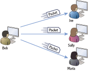
For example, consider Figure 2-2. Bob’s computer is broadcasting a packet on the network, and each of the computers on the subnet will receive and process the packet.
Figure 2-2: Broadcast: one to all
Notice that there is a slight difference in the language defining a unicast packet and a broadcast packet. This difference is important.
- Unicast traffic is one-to-one traffic between two computers on a network (not just on a subnet).
- Broadcast traffic is traffic sent from one computer to all other computers on a subnet (not the entire network).
Routers and Broadcast Exceptions
What is consistent with almost all rules is that there are exceptions. This is true with routers and broadcast transmissions.
First, let’s repeat the rule. Routers do not pass broadcasts. Routers separate subnets, and broadcasts in one subnet will not reach computers in another subnet.
Except…it is possible to program a router to pass broadcasts.
For example, consider the Dynamic Host Configuration Protocol (DHCP). A DHCP server provides IP addresses and other information to DHCP clients. Both the DHCP clients and DHCP server use a special type of broadcast known as a BootP broadcast. Routers can be programmed to pass these broadcasts on UDP ports 67 and 68. This allows a single DHCP server to serve multiple DHCP clients even if they are on separate subnets.
All the computers on the subnet will receive a broadcast packet. However, if the network has more than one subnet, all the computers on the network will not receive the packet. In other words, broadcast traffic does not cross subnets. Routers separate subnets, so another way of saying this is that routers do not forward broadcasts.
Computers are connected within a subnet using hubs or switches. Both hubs and switches do pass broadcast traffic.
You can think of a broadcast similar to how one person in a room can yell something and everyone in the room can hear it. Compare this to a unicast message, where one person whispers something so that only one other person hears it.
Chapter 6 covers IPv6 and includes a description of anycast traffic. Anycast sends traffic to one of many computers on a list and is more efficient than broadcast.
Understanding Multicast Traffic
Multicast traffic is transmitted from one computer to many other computers. When a computer joins a multicast group, the NIC is internally configured to process traffic using the multicast group’s IP address. Now, when traffic is multicast to the multicast group, any computers that have joined the multicast group will receive and process the packet. Multicast traffic will pass to different subnets.
Multicast traffic is one-to-many traffic on a network.
Consider Figure 2-3. Multicast traffic sent by Bob’s computer will reach multiple computers. In this scenario, Joe and Maria’s computers have joined the multicast group, and they will receive the traffic. Sally’s computer has not joined the multicast group and will not receive the traffic.
Figure 2-3: Multicast: one to many
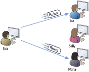
In most network configurations, the multicast traffic won’t even reach Sally’s computer. However, even if it does, the NIC will determine that the traffic is not destined for Sally’s computer, and the packet won’t be processed.
Internet Group Multicast Protocol (IGMP) is the primary protocol used to transmit and process multicast traffic.
Understanding Network Hardware
Computers are connected within a network using several networking components. Computers have network interface cards. Cables connect the wired network interface cards on the computers to network devices such as switches. Routers connect the different subnets on a network.
Networks can be either wired or wireless. Wired networks have cables, but wireless networks connect using radio frequency broadcasts.
Before going too far, it’s important to understand some basic terms:
Collision Domain A collision domain is group of devices on the same segment that are subject to collisions. Collisions occur when two devices on the same segment send traffic at the same time. In other words, only one device can send data at any given time. If a collision occurs, both devices must then resend the data. Collisions are not good, and excessive collisions degrade the network performance.
In this context, a segment is a common connection between multiple computers.
Broadcast Domain A broadcast domain is a group of devices on a network that can receive broadcast traffic from each other. In other words, if one device sends a broadcast packet, all other devices in the broadcast domain will receive it. Broadcasts are necessary, but it’s useful to limit the number of computers in a broadcast domain.
Different devices are used to create separate collision domains and separate broadcast domains. Although the following sections cover many devices, it’s important to understand how switches and routers are related to collision and broadcast domains:
Switches Switches connect computers in a network. Switches create separate collision domains. A switch passes broadcast traffic to all connections so it does not separate broadcast domains.
Routers Routers connect networks. Routers do not pass broadcast traffic. Routers create both separate collision domains and separate broadcast domains.
This section covers the following devices and components:
- Hubs
- Switches
- Bridges
- Routers
- Firewalls
- Media (such as cables)
Understanding Hubs
Hubs provide basic connectivity for devices in a network. Although these were once common devices on Ethernet networks, switches have replaced them in most networks today. A hub doesn’t have any intelligence, and any data that is sent to one port is forwarded to all ports.
You may still see some hubs in networks today. For example, some USB hubs are popular in smaller networks.
A port in this context is a physical connection. You plug one end of the cable into the port of the hub, and you plug the other end of the cable into the network interface card on the computer.
Consider Figure 2-4, which shows a four-port hub with different computers connected to the different ports. If Bob’s computer sends a unicast packet to Sally’s computer, the same packet will also reach Joe and Maria’s computers. The NIC on Joe’s and Maria’s computers will recognize the packet is not destined for them, so the traffic won’t be processed by their computers. However, the traffic can cause collisions if either Joe or Maria is trying to send data at the same time.
Ports can be physical or logical. A physical port is a physical connection on a network device. A logical port is a number used to identify a protocol or service.
Figure 2-4: Four-port hub

This is a result of all these computers being in the same collision domain. Also, hubs forward broadcasts so all of these computers are in the same broadcast domain.
As mentioned previously, collision domains and broadcast domains are important topics. If you can reduce the number of collisions in a network, it performs better.
Switches allow you to create more collision domains, reduce collisions, and improve network performance.
Figure 2-4 shows a four-port hub, so there really isn’t that much extra traffic on this network. However, when hubs were popular in production environments, they would often have 24 or more ports. Additionally, it was common to daisy-chain multiple hubs together on the same network which would create large collision domains.
Understanding Switches
Switches connect computers within a network similar to how hubs connect the computers. However, switches improve the performance of a network since they isolate the computers into separate collision domains.
Switches have multiple capabilities that can provide significant performance enhancements for any network. Chapter 8 presents switches in more depth.
Consider Figure 2-5, which shows a switch replacing the hub from Figure 2-4 (shown previously). Now, when Bob sends a unicast packet to Sally, the traffic reaches only Sally’s computer. The packet will not reach either Joe’s or Maria’s computer, so it can’t collide with data sent by these other computers.
Figure 2-5: Four-port switch

The switch dynamically determines the destination port as traffic is received. In the first example, it determines that the traffic should flow from port 1 to port 3. However, if Maria’s computer sends unicast traffic to Bob’s computer, the switch makes a different determination and instead sends traffic from port 4 to port 1.
Since the switch can dynamically determine which port to send traffic through, it effectively has separated the computers into four separate collision domains. Since a switch passes broadcasts, all the computers connected via the switch are in a single broadcast domain.
Switches learn which computer is connected to which port. Chapter 8 explains the technical details of how this is done, but in short, the switch tracks the location of the computers. As each computer sends packets on the network through the switch, the switch then identifies the computer and the port that it’s using. It maintains a table identifying the computers and their ports.
Switches track the location of computers connected on the switch’s ports.
Understanding Bridges
A bridge is a network device that connects two or more network segments together. Any of the segments can have one or more computers on it. For example, one segment could have 10 computers connected together with a hub, and another segment could have another 5 computers connected together with a different hub.
Bridges aren’t as common in networks anymore, but you may still run across them. A bridge is similar to a switch in that it will learn which port a computer is connected to and will internally switch traffic to the right port. The separate ports create separate collision domains.
However, multiple computers are connected to each port on a bridge. Separate hubs connect these computers together, and then the hub is connected to the bridge. The alternative is to daisy-chain each of the hubs together to create a single collision domain.
For example, imagine that four 24 port hubs are used to connect 96 computers in a single network. This results in a collision domain of 96 computers where 96 computers are all competing to send their data on the network.
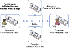
Instead, a bridge can connect these four hubs, as shown in Figure 2-6. The bridge creates four separate collision domains of 24 computers each. Computers on each of these separate collision domains are only competing with 23 other computers to send their data, instead of 95 other computers.
Figure 2-6: Four-port bridge creating four collision domains
Another benefit of bridges is that they can connect dissimilar physical topologies. For example, one port can connect computers using twisted-pair cables, and another port can connect computers using fiber-optic connections. Both wired and wireless bridges also exist. Wireless bridges are commonly used to connect a wireless access point (WAP) to another type of device on a wired network.
Understanding Routers
Routers are used to move packets between networks or subnets. Switches (or hubs) connect the devices within the subnet, and routers connect the subnets. You may remember from the previous section that switches track computers. However, routers do not track individual computers but instead track networks or subnets within a network.
Routers track subnets within a network. In comparison, switches track computers on a subnet.
Consider Figure 2-7, which shows subnet A with two computers connected via a hub. Subnet B has four computers connected with a switch.
Figure 2-7: Two subnets connected by a router
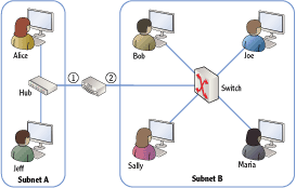
Can you tell how many collision domains and how many broadcast domains are in this figure?
All the computers connected via the hub are on one collision domain. Each of the users connected to the switch makes up four more collision domains. Last, the connection between the router and the switch make up a sixth collision domain. There are two subnets (subnet A and subnet B), and each subnet is a separate broadcast domain.
Routers direct, or route, traffic throughout a network. When a router receives a packet, it identifies the best path for the packet to take in order for it to arrive at the final destination. In Figure 2-7, there are only two subnets, so the router doesn’t have to make many decisions.
However, consider Figure 2-8, which is a multiple subnet network connected via several routers. The routers learn the locations of all the subnets and determine the best path to take to get traffic to its destination.
Figure 2-8: Network with multiple subnets separated by routers

For example, what if Sally wants to access the Internet? How many routers will she have to go through to get to the Internet? How about Bob? Notice Sally has to go through two routers (router 3 and router 1), while Bob has to go through only one router. Although that’s easy to see in the diagram, the routers do a lot of work to learn these paths.
One way that routers determine the best path to take is by talking to each other. Routers use different types of routing protocols that help them learn the network and the paths to different subnets. Some routing protocols are used only in internal networks, while other routing protocols are used only on the Internet.
Chapter 9 covers routers in more depth, including the use of routing protocols.
Routers and Default Gateways
Each computer on a subnet is configured with an IP address of the router. However, in this context it isn’t called a router but is instead called the default gateway.
If you look at Figure 2-7, computers on subnet A use the IP address of port 1 of the router as their default gateway. Computers on subnet B use the IP address of port 2 of the router as their default gateway.
Figure 2-8 shows multiple routers with a subnet in the center (labeled as a server subnet). The server subnet connects with four separate subnets. However, computers can be configured with only one default gateway.
The default gateway often provides a path to the Internet. Therefore, computers in the server subnet will most likely be configured with the IP address of port 1 of router 1.
Understanding Firewalls
Firewalls provide a layer of protection for computers and networks by keeping malicious or unwanted traffic from flowing in or out of a network. The most basic firewall is simply a router with rules. These rules control both inbound and outbound traffic.
Consider a firewall in an automobile. It’s located between the engine compartment and the passenger compartment. If a fire starts in the engine, the firewall prevents the fire from coming into the passenger compartment, or at least slows it down. Similarly, firewall rules prevent undesirable traffic from entering or leaving a network.
Firewalls can be network-based or host-based. Look at Figure 2-9 as you review these two types:
Network-Based Firewall A network-based firewall provides protection for an entire network. Most networks have at least one firewall between the Internet and the internal network. This firewall filters all traffic in and out of the network. Network-based firewalls are a combination of hardware and software.
Host-Based Firewall Many systems include individual firewalls also known as host-based firewalls. For example, Microsoft Windows 7 and Microsoft Windows Server 2008 servers (and many other desktop and server operating systems) include a software firewall. This software firewall filters traffic that passes in or out of the system. Additionally, security software suites often include software-based firewalls.
Figure 2-9: Network-based and host-based firewalls

Network-Based Firewall, Host-Based Firewall, or Both?
As a best practice, most organizations enable both network-based and host-based firewalls. A common question is, “Is a host-based firewall really needed if a network-based firewall is used?” The answer is yes.
Not all malicious traffic comes from the Internet. If someone inadvertently releases malicious software on an internal network (perhaps by plugging in an infected USB), the network-based firewall doesn’t provide any protection.
However, if each internal computer has a host-based firewall, the internal computers have an added layer of protection. This is a common security principle known as defense in depth.
Basic firewalls filter traffic based on the contents of packets such as source and destination IP addresses. Advanced firewalls can examine all the traffic in a session and make decisions based on the session traffic. Chapter 11 digs into firewalls in more depth, including advanced firewalls. Advanced firewalls can examine all of the packets within a session and analyze the conversation. Basic firewalls can only analyze individual packets.
Understanding Media
Routers connect networks together. Switches and hubs connect computing devices together. All of these devices are connected together using some type of transmission media.
Today’s networks use twisted-pair, fiber-optic, and wireless connections. Both twisted-pair and fiber-optic media are cables you can touch. However, wireless connections use transceivers to transmit and receive radio frequency transmissions over the air.
Chapter 7 covers the details of twisted-pair and fiber connections. Chapter 12 covers the details of wireless networking.
Twisted pair is used for short distances up to 100 meters. Fiber-optic runs can be as long as 2 km for multimode fiber and up to 40 km for single-mode fiber. Wireless networks are primarily used within buildings.
The most common type of transmission media is twisted pair. Twisted-pair cables can be wired as either a straight-through cable or a crossover cable.
Straight-Through Cable Wires are connected to the same pins on both connectors of a straight-through cable. A straight-through cable connects computers to networking devices. For example, it would connect a computer to a hub or a computer to a switch.
Figure 2-10 shows the wiring diagram of a straight-through cable. Just as the name implies, the connections are straight through end to end and each wire is connected on the same pins on both ends. The colors of the cable are based on the T568B standard.
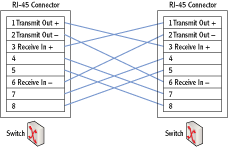
Crossover Cable Specific wires are crossed on opposite connectors of the crossover cable. A crossover cable connects similar devices to each other. For example, you would use a crossover cable to connect any two networking devices together such as the following:
- A switch and a switch
- A switch and a hub
- A switch and a router
- A computer and a computer
Figure 2-11 shows the wiring diagram for a crossover twisted-pair cable. The straight-through cable has the pairs connected from the same pins on one side to the same pins on the other side. However, the crossover cable crosses over some key wires so that transmit signals on one side go to receive on the other side.
Many modern routers and switches autosense the connection. In other words, if the connection needs a crossover cable, the wiring is internally changed.
You can easily identify a crossover cable by placing both connectors of the same cable side by side. If the orange and green pairs are swapped, it’s a crossover cable.
Figure 2-10: Straight-through cable
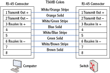
Figure 2-11: Crossover cable
T568A or T568B
An older wiring standard is T568A. The primary difference between T568A and T568B is that the colored pairs go to different pins. In T568A, the orange and green pairs are located on different pins than they are with T568B. Specifically, the orange pair is moved to pins 3 and 6 (pin 3 is white/orange, and pin 6 is orange), and the green pair is moved to pins 1 and 2 (pin 1 is white/green, and pin 2 is green).
It really doesn’t matter which standard you use as long as the same standard is used on both ends of the cable. If you have one end wired as T568A and the other end as T568B, you have created a crossover cable.
Exploring Protocols and Services
Protocols provide the rules that computers and other devices use to communicate with other computers and devices on networks. As long as the computers are able to follow the rules, they can access resources on the network.
If devices don’t follow the rules of the protocols, they simply aren’t able to communicate properly on the network. Obviously, computers don’t “break the rules” of the protocols just to see what they can get away with. However, if users or administrators accidentally misconfigure the protocols, it has the same effect—the misconfigured system won’t function properly on the network.
Services are processes that run on a computer without any user interaction. In comparison, a user launches an application. Many of the services will start when a computer is first started and before the user is able to do anything. Other services start later either based on a delay or when needed.
Exploring Protocols
Network protocols are formally defined in official documents by standards organizations. For example, RFC 791 defines the IPv4 protocol used on the Internet and internal networks.
As a reminder, the Internet Engineering Task Force (IETF) defines the protocols used on the Internet using requests for comments (RFCs) documents.
The primary protocol suite in use today is Transmission Control Protocol/Internet Protocol (TCP/IP). It is used on the Internet and most internal networks including Microsoft networks.
Notice that this isn’t a single protocol or even just the two protocols of TCP and IP. It’s a full suite of protocols. When a computer wants to access a website on the Internet, it uses Hypertext Transfer Protocol (HTTP). Email is transferred using Simple Mail Transfer Protocol (SMTP), Post Office Protocol version 3 (POP3), or Internet Message Access Protocol version 4 (IMAP4). Similarly, there are other protocols for other uses.
Although you don’t need to understand the inner workings of these protocols at this stage of your learning, you should be aware of the primary protocols used to communicate within networks and on the Internet. As your networking knowledge increases, you’ll need to know what protocols should be enabled to perform specific functions and what protocols are not needed.
Administrators commonly configure many protocols on networks. For example, IP addresses are manually assigned to many devices such as routers and servers within a network. Additionally, Dynamic Host Configuration Protocol can be configured on a network to dynamically assign IP addresses and other TCP/IP information.
Chapter 3 introduces many of primary protocols you should know about and maps these protocols to the OSI model. Chapter 4 digs into these TCP/IP protocols a little deeper.
Understanding Services
Many of the services running on Windows systems provide network capabilities. For example, the DHCP client service on a DHCP client computer obtains an IP address and other TCP/IP configuration information from a DHCP server over the network.
Windows Server 2008 has about 120 default services, and a typical installation has more than 50 starting by default.
Figure 2-12 shows the Services applet in Windows Server 2008. The Windows Firewall service is selected, and you can see that the current status is Started. Also, Startup Type is set to Automatic, meaning that it will automatically start when Windows starts.
Figure 2-12: Services applet

You can access the Services applet in Windows Server 2008 by clicking Start, entering Services in the Start Search text box, and clicking Services.
The different startup types for services are as follows:
Automatic The service will automatically start when the computer boots. The user is not able to interact with the system until all services set to Automatic have started.
Automatic (Delayed Start) The service will automatically start after all services set to Automatic have started. Users are able to interact with the system before these services start.
Manual The service starts when required. The service can be started by other services, applications, or the user.
Disabled The service cannot start. Unneeded services are set to disabled but can be enabled if it is later determined that the service is needed.
Understanding Basic Topologies
Chapter 1 presented the terms LAN and WAN. A local area network (LAN) is a group of computers and other devices connected together in a single physical location. A wide area network (WAN) connects two or more LANs over a larger distance.
It’s also important to understand the differences between an intranet, the Internet, a perimeter network, and an extranet. Consider Figure 2-13, which shows each of these topologies.
Chapter 11 digs deeper into intranet, extranet, and perimeter network configurations. These different topologies create different security zones.
Figure 2-13: Internet, extranet, intranet, and perimeter network

Internet Unless you grew up in a cave, you’ve used the Internet. It’s a massive network of computers connecting millions of smaller networks. The Internet uses the TCP/IP protocol suite. Computers connected to the Internet are able to reach any other computer on the Internet no matter where they are in the world.
Computers on internal networks may be able to access the Internet, but they aren’t directly connected it. These computers have a layer of protection from other computers on the Internet.
Intranet An intranet is an internal network using the TCP/IP protocol suite. The primary difference between an intranet and the Internet is that an intranet is private. Users on the Internet are not able to communicate directly with computers in an intranet. Computers within an intranet have a higher level of trust amongst themselves than computers on the Internet.
Perimeter network A perimeter network is a network between the Internet and the intranet. Firewalls filter the traffic to servers in the perimeter network. Servers in the perimeter network may be accessible by a user on the Internet. However, the firewall does limit the type of traffic allowed to these servers.
A perimeter network is also called a demilitarized zone (DMZ).
Extranet An extranet is similar to a perimeter network. However, the biggest difference is in the intent. Servers on the extranet are accessible only to trusted entities such as trusted business partners or specific customers or vendors. These trusted entities can access the extranet via the Internet. Different methods and technologies ensure that nontrusted entities are not able to access servers on the extranet. Notice that users in the intranet also have access to resources in the extranet. However, the firewall will prevent users in the extranet from accessing resources in the intranet.
The Essentials and Beyond
This chapter provided an overview of many basic networking components. You learned the basics of unicast, broadcast, and multicast transmissions. You also learned basics on how hubs and switches connect computers and how routers connect networks. Networks are connected using different types of media such as twisted pair, fiber optic, or wireless. Protocols are the rules used by devices to communicate. The protocol suite used on the Internet and Microsoft networks is TCP/IP.
Additional Exercises
- Identify the type of media used in your network. Is it fiber optic, twisted pair, or wireless?
- Identify the types of network devices used in your network.
- Draw a logical network diagram. The diagram should include servers that are available to trusted partners via the Internet.
- Identify whether a computer you are using has a firewall enabled.
To compare your answers to the author’s, please visit www.sybex.com/go/networkingessentials.
Review Questions
1. What type of traffic always goes to all devices in a subnet?
|
A. Unicast |
C. Broadcast |
|
B. Multicast |
D. Allcast |
2. True or false. A switch blocks broadcasts.
3. What is the difference between a switch and a router?
|
A. Nothing. They are the same. |
|
B. Switches do not pass broadcasts, but routers do. |
|
C. A switch connects devices together, and a router connects subnets together. |
|
D. A switch connects subnets together, and a router connects devices together. |
4. True or false. Bridges can connect dissimilar physical topologies.
5. A firewall uses _____________ to filter both inbound and outbound traffic.
6. A network-based firewall is a hardware device that provides protection for a network. What is a host-based firewall?
7. True or False. A crossover cable is used to connect a computer to a switch.
8. Which of the following standards define how twisted-pair cables should be wired?
|
A. IEEE 802.3 |
C. Extranet wiring practices |
|
B. RFC 791 |
D. T568B |
9. A company wants to host a web server for Internet users. The web server should be placed in _____________.
10. What is used to provide access to a company’s resources via the Internet to trusted partners?
