Chapter 5
Exploring IPv4
IPv4 addresses are the most common types of addresses used on the Internet and in internal networks today. It’s important to understand the components of an IPv4 address so that you can easily troubleshoot basic problems when a computer has been misconfigured.
Large organizations often divide the network into subnets, and one of the rites of passage for networking is to understand how subnetting works. You don’t have to be a master at subnetting, but you should understand the basics.
Most organizations also use the Dynamic Host Configuration Protocol (DHCP) to automatically assign IP addresses and other TCP/IP configuration information. Although this normally works well, it occasionally fails. When a client can’t reach a DHCP server, it gives an obvious telltale sign—if you know what to look for.
- Exploring the components of an IPv4 address
- Exploring an IPv4 address in binary
- Subnetting IPv4 addresses
- Comparing manual and automatic assignment of IPv4 addresses
Exploring the Components of an IPv4 Address
Internet Protocol version 4 (IPv4) has been the standard IP addressing scheme since the 1980s. It’s used to get TCP/IP traffic from one computer to another computer over a network. All computers on the Internet have unique IP addresses. As long as the IP addresses are valid, any computer can reach any other computer on the Internet with this IP address.
Similarly, internal networks also use IP addresses. All computers on each internal network have unique addresses within the network, and these IP addresses are used to get traffic from one computer to another.
You can think of an IP address like the street address of a home or business. As long as the full address is valid, you can address a letter, and the post office will deliver it. This also works worldwide. If you have a valid address, your letter will reach its destination. A valid address in the United States has a street address or a post-office box, a city, a state, and a zip code.
Valid IP addresses have four decimals separated by three dots. Additionally, the only valid decimal numbers in an IPv4 address are 0 through 255. For example, the following IP addresses are valid:
An IPv4 address expressed with decimal numbers separated by dots is in dotted decimal format, or dot-decimal notation.
- 10.80.1.5
- 172.16.5.254
- 192.168.1.4
In comparison, the following are not valid IPv4 addresses:
- 10.80.256.5: No number can be greater than 255.
- 172.16.254: There must be four decimals.
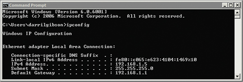
You can tell what your configured IP address is by using the ipconfig command at the command prompt. The following steps show how to do this on a Windows system.
These steps will work on a variety of Windows systems including Windows 7 and Windows Server 2008.
1. Click Start Run.
2. Type in cmd in the Run box, and press Enter.
3. At the command prompt, type ipconfig, and press Enter.
Your display will look similar to Figure 5-1, though you’ll probably have different IP addresses displayed. In the figure, both an IPv4 address and an IPv6 address are shown, though you may have only an IPv4 address. Additionally, you can see that the system is using a default gateway of 192.168.1.1.
The default gateway is the address of the near side of a router. It will typically provide a path to the Internet or other subnets and is explained further later in this chapter.
Figure 5-1: Viewing the IP address with ipconfig
Ascertaining the Network ID and Host ID of an IP Address
An IP address has two components: a network ID and a host ID. The network ID identifies the subnetwork, or subnet where the computer is located. The host ID uniquely identifies the computer within that subnet.
Comparing a Network ID and a Zip Code
A postal address includes the street address, city, state, and zip code. When the postal service receives a letter, it will get it to the post office in the correct city and state simply by using the zip code. The postal service then uses the street address to get it to the correct home or business.
Similarly, TCP/IP uses the network ID to get a packet to a router in the correct subnet. Once the packet reaches the subnet, it uses the host ID to get the packet to the correct computer on the subnet.
Throughout the United States, zip codes are unique. Each zip code represents a group of addresses relatively close to each other. Similarly, within a network, network IDs are unique. Each network ID represents a group of two or more hosts on a subnet of a network.
Within each zip code, each address is unique. For example, you can’t have two addresses of 777 Success Road. If the addresses were the same, mail couldn’t be accurately delivered to both addresses. Similarly, within a subnet, computers with the same network ID must have unique host IDs. If two computers have the same host ID and the same network ID (the same IP address), it results in an IP address conflict.
In internal networks, IP addresses are accompanied by a subnet mask. The subnet mask identifies the portion of the IP address that is the network ID. The following are common subnet masks:
Subnet masks can be more complex, but many internal networks use simple subnet masks with only the numbers 255 or 0 in dotted decimal format.
- 255.0.0.0
- 255.255.0.0
- 255.255.255.0
TCP/IP uses the subnet mask to determine which portion of the IP address is the network ID and which portion is the host ID. More specifically, when the subnet mask is configured at its maximum value (255), that indicates that the corresponding portion of the IP address is part of the network ID. The remaining portion of the IP address is the host ID.
Consider an IP address of 192.168.1.5 with a subnet mask of 255.255.255.0. Figure 5-2 and Table 5-1 show the two parts of this IP address.
Since the first three decimals of the subnet mask are 255, the first three decimals of the IP address make up the network ID. The network ID is always expressed with trailing zeros. In other words, the network ID in this case is 192.168.1.0. It’s incorrect to express it as 192.168.1 without the trailing zeros. The host ID is simply whatever remains after identification of the network ID. In this case, the host ID is the number 5.
Figure 5-2: An IP address with a subnet mask

Table 5-1 The two parts of an IP address
The subnet mask must have contiguous maximum numbers. In other words, once the first zero is used, the remaining numbers must be zero. A subnet mask of 255.0.255.0 is not valid.
When using advanced subnetting, this rule is worded a little more specifically. Once the first zero bit is used, the remaining bits must be zero.
Identifying the network ID and host ID is very important. Every computer on a subnet must have the same network ID as part of their IP address, and each of these computers needs a unique IP address. When IP addresses are manually assigned, a simple typo can result in a computer not communicating at all.
Consider Figure 5-3. You should be able to identify the network ID and the host ID of each of the computers in the two subnets. Additionally, the configuration of two of the computers in subnet A and two of the computers in subnet B are incorrect. The addresses assigned to the router interfaces are correct. Can you identify the errors?
Figure 5-3: Identifying the network ID

The answers are given in the following text, but see whether you can figure out the answers on your own before checking your answers.
Notice in the figure that subnet A is on the left and subnet B is on the right. They are separated by a router. The router has two network interface cards (NICs), and each NIC is assigned an IP address. For all computers in subnet A, the NIC labeled A is the default gateway to subnet B. Similarly, for all computers in subnet B, the NIC labeled B is the default gateway to subnet A.
It’s common to give a default gateway the first IP address in the subnet such as 192.168.1.1. However, this is not required.
Router Connection A The network ID is 192.168.1.0, and the host ID is 1. Since this is known to be correct, all computers on this subnet must have the same network ID (192.168.1.0). NIC A on the router is the default gateway for computers on subnet A.
Computer 1 The network ID is 192.168.1.0, and the host ID is 5. This computer is configured correctly.
Computer 2 The network ID is 192.168.1.0, and the host ID is 6. This computer is configured correctly.
Computer 3 The network ID is 192.168.2.0, and the host ID is 7. Notice that the network ID is different from the default gateway. Since the network ID is different from other computers on this subnet and also different from the default gateway, this computer won’t be able to communicate on the network.
Computer 4 The network ID is 192.168.0.0, and the host ID is 1.8. Notice that the subnet mask is 255.255.0.0 with only two 255s instead of three. Since the network ID is different from other computers on this subnet and also different from the default gateway, this computer won’t be able to communicate on the network.
Router Connection B The network ID is 192.168.4.0, and the host ID is 1. Since this is known to be correct, all computers on this subnet must have the same network ID (192.168.4.0). NIC B on the router is the default gateway for computers on subnet B.
Computer 5 The network ID is 192.168.4.0, and the host ID is 5. This computer is configured correctly.
Computer 6 The network ID is 192.168.14.0, and the host ID is 6. Notice that the third number in the IP address is 14 and not 4. Since the network ID is different from other computers on this subnet and also different from the default gateway, this computer won’t be able to communicate on the network.
Computer 7 The subnet mask of 255.0.255.0 is invalid. A valid subnet mask can’t have numbers greater than zero once the first zero is used. This computer won’t be able to communicate on the network.
Computer 8 The network ID is 192.168.4.0, and the host ID is 8. This computer is configured correctly.
Identifying the Default Gateway
The default gateway is the IP address of the router on the local subnet. If there’s only one router (as shown in Figure 5-3 earlier), it’s easy to determine the default gateway. However, if a subnet has more than one router, only one can be the default. The default gateway will usually provide a path to the Internet.
Consider Figure 5-4. It includes three routers with multiple subnets shown. Subnets x, y, and z have computers and IP addresses assigned, but this discussion is focused on subnet A and subnet B. All the IP addresses in subnet A have a network ID of 192.168.1.0, and all the IP addresses in subnet B have a network ID of 192.168.4.0. Notice that both subnet A and subnet B have two routers. However, only one router will provide a path to the Internet.
Figure 5-4: Identifying default gateways

If this is a typical network, all the computers in subnet A will be configured with a default gateway of 192.168.1.1, and all the computers in subnet B will be configured with a default gateway of 192.168.4.1.
Determining Local and Remote Addresses
The IP protocol looks at the source and destination addresses to determine whether they are both on the same local subnet. If they are on the same subnet, it then uses the Address Resolution Protocol (ARP) to broadcast the IP, learn the physical address, and deliver the packet to the destination computer.
However, if the destination IP address has a different network ID, it is considered to be on a remote subnet. The IP protocol then sends the data to the default gateway.
You should be able to look at two IP addresses and determine whether they are both on the same local subnet or whether the destination IP address is on a remote subnet. You can do this with the following steps:
1. Determine the network ID of the source IP address.
2. Determine the network ID of the destination IP address.
3. Determine whether they are the same:
- If so, they are local to each other.
- If not, the destination address is on a remote network and data must be sent through the default gateway.
Give this a try with the following examples. See whether you can determine if the two IP addresses are local (with the same network ID and on the same subnet) or remote (with different network IDs and on different subnets).
The following text provides the answers to this challenge, but see if you can figure them out before checking your answers:
Example 1 The network ID of the source IP address is 192.168.1.0. The network ID of the destination IP address is 192.168.1.0. These are the same, so they are local to each other.
Example 2 The network ID of the source IP address is 10.80.0.0. The network ID of the destination IP address is 10.80.0.0. These are the same, so they are local to each other.
Example 3 The network ID of the source IP address is 192.168.1.0. The network ID of the destination IP address is 192.168.11.0. These are different, so the destination IP address is remote.
Understanding Classful IP Addresses
IPv4 is a classful logical addressing scheme using three primary address classes: Class A, Class B, and Class C. The class of the address is determined by the first number in the IP address. Additionally, the subnet mask is predetermined for each class. Table 5-2 shows these three IP ranges with an example IP address in each class.
You should be able to identify the class of any classful IP address, its subnet mask, and its network ID.
Table 5-2 Classful IP addresses

Notice that the first example IP address (10.80.1.15) has a 10 as the first number. The number 10 is in the range 1 through 126, making this a Class A address, with a subnet mask of 255.0.0.0 and a network ID of 10.0.0.0. The second example IP address (172.16.32.15) has the number 172 first, making it a Class B address with a subnet mask of 255.255.0.0 and a network ID of 172.16.0.0. The third example (192.168.1.5) has a 192 first, making it a Class C address with a subnet mask of 255.255.255.0 and a network ID of 192.168.1.0.
Understanding Class D and Class E Addresses
Class D and Class E addresses also exist but aren’t as important when understanding classful addressing. Class D is used for multicasting and includes the address range from 224.0.0.0 through 239.255.255.255. Class E is a reserved range from 240.0.0.0 through 255.255.255.255,
Computers are able to determine whether the IP address is a Class A, Class B, or Class C address by looking at only the first two bits in the address. These are the high-order bits with values of 128 and 64, as shown in Table 5-3. Notice that a Class A address has a range of 1 through 126, so the first two bits may be 0 or 0 and 1. Class B has a range 128 through 191, and the highest-order bit is always a 1, and the second bit is always a 0. Class C has a range of 192 to 223, and the two high-order bits are always a 1.
High-order bits are simply the bits with the highest value. In a binary octet, the two high-order bits are on the farthest left with values of 128 and 64.
Table 5-3 Identifying the upper-level bits of Classful IP addresses
Figure 5-5 shows the three classful IP address ranges with their network ID and host IDs separated. It also shows the value of the high-order bits for each of these classes.
One of the benefits of using classful IP addressing is that you can determine the subnet mask by looking only at the IP address. Once you know the subnet mask, you can then determine the network ID. For example, see whether you can determine the network IDs of the following classful IP addresses:
192.168.1.3
172.16.4.7
10.80.20.4
Figure 5-5: Classful IP addresses

You need to determine the class of each, identify the subnet mask of the class, and then use that information to determine the network ID. Table 5-4 shows the result for each of these IP addresses.
You can test the TCP/IP stack on a local computer by issuing the ping 127.0.0.1 command from the command prompt. It should return four replies.
Table 5-4 Determining network ID of a classful IP address
Although most of the addresses in the three address ranges can be used, there are some restrictions. For example, you may have noticed that the entire range starting with 127 is missing. This Class A address range is reserved for testing. The address of 127.0.0.1 is known as the loopback address and is used to test the installed NIC. There are also several other IP address ranges reserved for use on internal networks only.
Identifying Reserved IP Address Ranges
RFC 1918 identifies several IP address ranges for use in private networks only. These addresses aren’t assigned to any computers on the Internet but instead are assigned to computers on internal networks. These private IP ranges are as follows:
A special Automatic Private IP Addressing (APIPA) range is from 169.254.0.1 through 169.254.255.254. APIPA is described later in this chapter.
10.0.0.0 through 10.255.255.255
172.16.0.0 through 172.31.255.255
192.168.1.0 through 192.168.255.255
However, the first and last address in each range is not usable. The only usable addresses in these ranges are:
10.0.0.1 through 10.255.255.254
172.16.0.1 through 172.31.255.254
192.168.1.1 through 192.168.255.254
You may remember that IP addresses on the Internet must be unique. No two computers on the Internet can use the same IP address. However, since private addresses are internal to a company, different companies can use the same IP addresses on their internal networks. In other words, company A can use a range of 192.168.1.1 through 192.168.1.254 for computers in their network, and company B can use the exact same numbers.
Exploring an IPv4 Address in Binary
Although you can usually work with IPv4 addresses using the dotted decimal format, you occasionally need to dig a little deeper. The following section gives some in-depth information on the IPv4 address at the binary level.
Understanding the Bits of an IP Address
People have 10 fingers and generally count using the decimal system with a base of 10. However, computers only understand 1s and 0s and count using the binary system with a base of 2. Each binary number is a bit and can have a value of 1 or 0.
An IPv4 address has 32 bits. You’ll commonly see the IP address expressed in dotted decimal format, but it can also be expressed in four groups of eight bits. Each group of eight bits is also known as an octet in the IP address. In other words, an IP address has four decimals in dotted decimal format, which can also be expressed as four octets in binary format.
Octet means eight, and it’s accurate to say that an IP address has four octets. Eight bits is also a byte, and the address can be referred to as four bytes.
For example, Table 5-5 shows an IP address and subnet mask expressed in both decimal and binary form.
A logical question is “How does 192 in decimal equate to 1100 0000 in binary?” The answer is based on which bits are ones in the binary string. Table 5-6 shows the relative value of the binary bits. The low-order bit (20) is 1 since any number raised to the 0 power is 1. 21 is 2 since any number raised to the first power is equal to itself. The high-order bit (27) has a decimal value of 128.
Table 5-5 Comparing dotted decimal and binary

Table 5-6 Binary and decimal values
You should be able to reproduce Table 5-6 from memory so that you can convert binary numbers to decimal and back. Notice that each number doubles from right to left.
If the first two bits are a 1 (1100 0000), it represents one decimal value of 128 and one decimal value of 64. The sum or 128 + 64 equals 192. These 8 bits can represent any value between 0 and 255. If all eight bits are a 0 (0000 0000), the decimal value is 0. If all eight bits are a 1 (1111 1111), the value is 255.
Look at Table 5-7, and see whether you can determine the decimal values of the different examples. You can calculate the total decimal value by adding the decimal value for each bit that has a binary 1.
Table 5-7 Binary values

Here’s the solution to check your answers:
- Example 1 = 192 (128 + 64)
- Example 2 = 168 (128 + 32 + 8)
- Example 3 = 1 (1)
- Example 4 = 5 (4 + 1)
- Example 5 = 10 (8+ 2)
- Example 6 = 0 (none of the bits are a 1)
- Example 7 = 255 (128 + 64 + 32 + 16 + 8 + 4 + 2 + 1)
Notice that examples 1 through 4 are the binary values of the IP address 192.168.1.5. In binary form, the full IP address is 1100 0000 . 1010 1000 . 0000 . 0001 . 0000 0101.
Digit Grouping
When using decimal numbers, it’s common to group digits in threes separated by a comma for better readability. For example, the number 1,234,567 is easier to read than the number 1234567.
Similarly, binary numbers are grouped with four bits separated by a space. It’s easier to read 1100 0000 than it is to read 11000000. When digit grouping is used, it’s easy to see that it is two groups of four, but when digit grouping is not used, it’s not always apparent how many digits are in the binary string.
The actual value doesn’t change when digit grouping is used. The value of 1,234,567 is the same as 1234567, and the value of 1100 0000 is the same as 11000000.
A simpler way of converting binary to decimal and decimal to binary is with the calculator built into the Windows operating system. Figure 5-6 shows the Windows 7 calculator in the Programmer View (from the View drop-down menu). Other operating systems provide the same capability in the Scientific View.
After selecting the proper view in the calculator, enter the decimal number, and then click Bin to convert it to binary. If you want to convert it back to decimal, simply click Dec. You can also convert numbers to base 16 hexadecimal numbers (Hex) or base 8 octal numbers (Oct).
Use the calculator to check your work. Some exams include a calculator, but you can’t always count on a binary-to-decimal converter to be available.
Figure 5-6: Converting decimal to binary
Understanding CIDR Notation
The subnet mask is sometimes referenced in a type of shorthand called Classless Inter-Domain Routing (CIDR) notation based on the number of bits. For example, if the subnet mask is 255.0.0.0, it has 8 bits in use and can be referenced as /8. If the subnet mask is 255.255.0.0, it has 16 bits in use and can be referenced as /16. If the subnet mask is 255.255.255.0, it has 24 bits in use and can be referenced as /24.
Table 5-8 shows some example IP addresses expressed with CIDR notation.
Table 5-8 Examples of CIDR notation
| IP address | Subnet mask | CIDR notation |
| 192.168.1.5 | 255.255.255.0 | 192.168.1.5 /24 |
| 172.17.34.5 | 255.255.0.0 | 172.17.34.5 /16 |
| 10.80.4.7 | 255.0.0.0 | 10.80.4.7 /8 |
Masking the IP Address
An important point of this chapter is understanding that an IPv4 address includes two components: a network ID and a host ID. The subnet mask identifies which is which by masking out the network ID. This was shown earlier with decimal numbers. When the subnet mask is configured at its maximum value (255), that portion of the IP address is the network ID.
The same point is true when using binary numbers. Consider an IP address of 192.168.1.5 with a subnet mask of 255.255.255.0, as shown in Table 5-9. When the subnet mask is configured at its maximum (1 in binary), that portion of the IP address is the network ID.
Table 5-9 Masking an IP address

The computer looks at the first bit in the IP address (in this case it is set to 1) and the first bit in the subnet mask (also set to 1), and then ANDs them together, which yields a 1 as the first bit in the network ID. It then looks at the second bit in the IP address (1) and the second bit in the subnet mask (also set to 1) and is set to a 1 as the second bit in the network ID. It does this with each of the bits to determine the network ID.
You can do it bit by bit, but it is simpler to just look at which bits are 1s in the subnet mask and recognize that the corresponding bits in the IP address make up the network ID.
Boolean AND Logic
Within the computer, the “masking” is done by using Boolean AND logic. Boolean AND logic compares two bits and provides a single bit as the output. If both bits are a 1, the output is a 1. However, if either of the bits is a 0 or both bits are a 0, the output is a 0.
The following list shows the four possibilities when ANDing two bits:
- 0 AND 0 = 0
- 0 AND 1 = 0
- 1 AND 0 = 0
- 1 AND 1 = 1
Using Classless IP Addresses
Classful IP addresses include Class A, Class B, and Class C addresses as described earlier. Remember that when a classful IP address is used, the subnet mask is implied and doesn’t need to be included. Classless IP addressing can also be used.
When a classless IP address is used, you must have both the IP address and the subnet mask to determine the network ID. As an example, an address of 10.80.1.5 is a classful IP address with a subnet mask of 255.0.0.0 and a network ID of 10.0.0.0. However, Table 5-10 shows how the same IP address can be used as a classless IP address with different subnet masks, resulting in different network IDs.
Table 5-10 Examples of classless IP address
| IP address | Subnet mask | Network ID |
| 10.80.1.5 | 255.255.0.0 | 10.80.0.0 |
| 10.80.1.5 | 255.255.255.0 | 10.80.1.0 |
Classful IPv4 address ranges can be divided into smaller groups of addresses, therefore creating subnets. Smaller organizations rarely need to do this, but large organizations frequently subnet the network instead of using the typical classful IP address ranges.
Administrators and IT support personnel need to understand subnetting to ensure that systems have the correct IP addresses assigned. Earlier in this chapter you had the opportunity to compare different IP addresses and subnet masks for computers on a subnet to determine whether they were correct. This section has the same goal but with advanced subnetting techniques.
Consider a single class C network of 192.168.1.0 /24, as shown in Figure 5-7. It can host 254 computers on the same subnet.
Imagine that users on this network are in four primary groups as follows:
- One group is regularly streaming video from a server.
- Another group is regularly uploading and downloading large graphics files.
- A third group is downloading large volumes of data from the Internet.
- The last group is just a regular group of users with occasional server and Internet access.
Figure 5-7: A single Class C network
If all four groups of users are on the same subnet, their traffic will compete with each other for network bandwidth. The overall performance of the subnet may be slow. However, if the four groups are divided into different subnets, each subnet will enjoy better performance.
Determining the Number of Subnet Bits
In the example shown previously in Figure 5-7, it makes sense to create four separate subnets. This is done by borrowing bits from the host ID portion of the IP address and adding them to the network ID. They create a new portion of the network ID referred to as the subnet ID. If you borrow one bit, you can create two subnets. A single bit has two states, either a 1 or a 0, but you need four subnets, not two. If you borrow two bits, you can create four subnets.
Figure 5-8 shows how the single Class C address is subdivided by borrowing the two high-order bits from the host ID portion of the address. The Class C address has a subnet mask of 255.255.255.0, with 24 bits in the network ID portion of the IP address and 8 bits in the host ID portion.
If you borrow two bits from the original eight bits in the host ID portion, you now have six bits left for the host ID. The 24 bits of the original network ID and the two bits of the subnet ID are combined to give a total of 26 bits for the network ID.
This gives a new subnet mask of 255.255.255.192 must be used.
It’s important to realize that the two borrowed bits are the high-order bits in host ID. They have the values of 128 and 64. These two bits have four possible combinations of 0 0, 0 1, 1 0, and 11, which will be used within the host ID to create four separate subnets. Table 5-11 shows these combinations and their values.
Figure 5-7 shown earlier was a single large subnet of 254 hosts. By subnetting the Class C address, you can get the four subnets shown in Figure 5-9.
Figure 5-8: Creating subnets

Table 5-11 Subnetting with the two high-order bits
| 27 (Decimal 128) | 26 (Decimal 64) | Decimal value |
| 0 | 0 | 0 |
| 0 | 1 | 64 |
| 1 | 0 | 128 |
| 1 | 1 | 192 |
Notice that each subnet has a specific nonoverlapping range of IP addresses. This is an extremely important point. If you assigned an IP address of 192.168.1.200 to a computer in subnet A, it wouldn’t be able to communicate with any other computer since it has an incorrect network ID for the subnet.
If you wanted to create more subnets, you’d need to borrow more bits. You can use the following formula to determine how many subnets you can create based on how many bits you borrow: 2n, where n is the number of bits you borrow.
For example, if you borrow two bits (22), you can create four subnets. If you borrow three bits (23), you can create eight subnets. Of course, the more bits you borrow from the host ID, the fewer hosts that you can create in a network.
Figure 5-9: A subnetted network
Determining the Number of Hosts in a Network
Valid IP addresses cannot have all 0s in the host ID because that represents the network ID. Also, they can’t have all 1s in the host ID because that represents a broadcast address within the subnet. This eliminates two possible IP addresses in the range of IP addresses for any subnet.
For example, if you use a typical Class C network of 192.168.10 with a subnet mask of 255.255.255.0, you can’t have the following two IP addresses:
- 192.168.1.0 (since this is the network ID)
- 192.168.1.255 (since this is the broadcast address for the network ID)
This gives a valid range of 192.168.1.1 through 192.168.1.254 for a total of 254 possible hosts. You can determine how many hosts are supported in any subnet based on the following formula: 2h – 2, where h is the number bits in the host ID.
A Class C address uses 24 bits in the network ID and 8 bits in the host ID, so the formula is 28 – 2. This gives a value of 254 (28 is 256 and 256 – 2 = 254). Table 5-12 shows the number of hosts from a subnetted Class C address.
Although the discussion so far has been focused on subnetting a Class C network, the same concepts can be applied to subnet a Class B or Class A network. Remember, a Class B network starts with 16 bits for the network ID and 16 bits for the host ID. Table 5-13 shows the number of subnets and the number of hosts a subnetted Class B network will support.
Table 5-12 Determining the number of subnets and hosts in a Class C network

Table 5-13 Determining the number of subnets and hosts in a Class B network
A Class A network starts with 8 bits for the network ID and 24 bits for the host ID. Table 5-14 shows the number of subnets and the number of hosts a subnetted Class A network will support.
Table 5-14 Determining the number of subnets and hosts in a Class A network

What Is Supernetting?
You may run across the term supernetting in your studies. Although the process is more advanced than you’ll need to learn at this point, it is worthwhile understanding the big picture of supernetting. In short, supernetting is the opposite of subnetting.
You’ve learned that subnetting divides a larger network into multiple smaller networks by taking bits from the host ID. Supernetting combines multiple smaller networks into a single larger network by taking bits from the network ID. This is a useful function when optimizing routing devices on a network.
Identifying Local and Remote Addresses
Earlier in this chapter, you had the opportunity to determine whether simple IP address and subnet mask combinations were on the same subnet (local to each other) or whether the destination IP address was on a remote subnet. You should be able to make the same determination even when advanced subnetting techniques are used on your network.
As a reminder, the following steps are used to determine whether an address is local or remote.
1. Determine the network ID of the source IP address.
2. Determine the network ID of the destination IP address.
3. Determine whether they are the same:
- If so, they are local to each other.
- If not, the destination address is on a remote network and must be sent through the default gateway.
However, when advanced subnetting is used, it’s a little harder to determine the network ID. For example, it’s not readily apparent what the network ID is of the following IP and subnet mask combinations:
- Source IP: 192.168.1.61, 255.255.255.192
- Destination IP: 192.168.1.65, 255.255.255.192
You can simplify the process of determining the network ID with the following five steps:
1. Convert the IP address to binary. You can use a calculator to do this.
2. Convert the subnet mask to binary.
3. Draw a vertical line after the last one in the subnet mask:
Really, draw the line. It’s a simple step and provides an easy way to visually separate the network ID and the host ID.
- Everything to the left of the line is the network ID.
- Everything to the right of the line is the host ID.
4. Determine the network ID in binary. This is as simple as copying the IP address in binary to the left of the line and writing 0s to the right of the line.
5. Convert the network ID to decimal.
Figure 5-10 shows the steps for the 192.168.1.61 IP address, and Figure 5-11 shows the steps for 192.168.1.65.
Once you complete these steps, you can determine that the network ID of the source IP address is 192.168.1.0 and the network ID of the destination IP address is 192.168.1.64. These network IDs are not the same, so the destination IP address is remote.
Applying Subnetting Knowledge
On the job, subnetting knowledge is important because a misconfigured computer won’t communicate with other systems. You should be able to look at the IP address and determine whether it is correct.
Figure 5-10: Determining the network ID of 192.168.1.61

Figure 5-11: Determining the network ID of 192.168.1.65

At the beginning of this chapter, you had the opportunity to do some basic troubleshooting with Figure 5-3. It showed you the IP address and subnet mask of several computers with some computers configured incorrectly. However, those examples used subnet masks of 255.255.255.0 and 255.255.0.0 only. An actual network may have advanced subnet masks.
Take a look at Figure 5-12. The default gateways are configured correctly. The configured IP address, subnet mask, and default gateway are shown for each of these computers, but they aren’t necessarily configured correctly. Instead, they show common typo errors that occur when a system is configured manually.
Can you determine what computers are configured correctly and what the errors are for the other computers?
Remember, all computers on the same subnet must have the same network ID, and they must be configured with the correct IP address of the default gateway. Use the steps shown earlier to calculate the network ID of the default gateways and each of the computers on the subnets.
Figure 5-12: Troubleshooting IP addressing

The following text provides the solution to the challenge in Figure 5-12. After identifying all the errors you can find, check out these solutions.
Hint: Two of the computers are configured correctly. The remaining computers have errors.
Computer 1 The network ID of the computer is 192.168.129.0. However, the network ID of the default gateway is 192.168.129.64. Since the network IDs are different and the default gateway is known to be correct, the computer is configured with an incorrect IP address.
Computer 2 The network ID is 192.168.129.64, which is the same as the default gateway. This computer is configured correctly.
Computer 3 The network ID is 192.168.129.64, which is the same as the default gateway. However, the default gateway is configured incorrectly as 192.168.129.56 instead of 192.168.129.65.
Computer 4 The subnet mask is incorrect on this computer. All of the computers on the same subnet must have the same subnet mask. The network ID is 192.168.129.100, which is different from the network ID of the default gateway (192.168.129.64).
Computer 5 The network ID of the computer is 10.80.160.0, which is the same as the network ID of the default gateway. This computer is configured correctly.
Computer 6 The network ID of the computer is 10.80.128.0, which is different from the network ID of the default gateway (10.80.160.0). This computer is not configured correctly.
Computer 7 The network ID of the computer is 11.80.128.0 (notice the first octet is 11 instead of 10), which is different from the network ID of the default gateway (10.80.160.0). This computer is not configured correctly.
Computer 8 The network ID of the computer is 10.80.160.0, which is the same as the network ID of the default gateway. However, the default gateway is configured with an incorrect IP address. It should be 10.80.160.1 instead of 101.80.160.1.
As a final exercise with subnetting, consider a single Class C network with a network ID of 192.168.20.0 and a subnet mask of 255.255.255.0. You are tasked with dividing this network into two separate subnets.
See if you can answer the following questions:
What is the network ID of each subnet?
What is the subnet mask of each subnet?
What is the first IP address of each subnet?
What is the last IP address of each subnet?
The graphic at the end of the Understanding APIPA section in this chapter shows one possible solution for this challenge.
Comparing Manual and Automatic Assignment of IPv4 Addresses
IPv4 information can be assigned either manually or automatically. Manually means that you actually type in the IP address, subnet mask, default gateway, and other TCP/IP information such as the address of the DNS server into the configuration screens on each computer. Automatic assignment uses Dynamic Host Configuration Protocol (DHCP) server to assign the information to the computers without user intervention.
In most networks, it is much easier to use DHCP. The majority of the clients automatically get their TCP/IP configuration from a DHCP server. However, some clients may need to have a manually configured IP address. For example, the DHCP server must be assigned an address manually. Additionally, some clients don’t support DHCP, and devices such as routers need to be manually assigned.
Manually Configuring IPv4
You can use the following steps to manually view or configure the IPv4 information on a Windows Server 2008 server or Windows 7 system.
You can also just view the information here without changing it. If you are using a DHCP server, it will be set to Obtain An IP Address Automatically.
1. Click Start Control Panel.
2. Type Network in the Control Panel Search box. Select Network And Sharing Center.
3. Click Manage Network Connections in the Tasks pane on the left.
4. Right-click Local Area Connection, and select Properties.
5. Select Internet Protocol Version 4 (TCP/IPv4), and click Properties. Your display will look similar to Figure 5-13.
6. Enter the appropriate IP address, subnet mask, default gateway, and address of a DNS server.
Using DHCP
If your system is configured to obtain an IP address automatically, a server on your network will be running DHCP. Windows Server 2008 servers include the DHCP role and can be configured to run DHCP.
Figure 5-13: Viewing the IPv4 configuration of the NIC
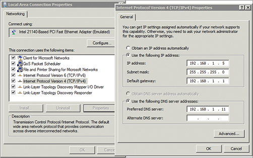
Figure 5-14 shows the process a DHCP client uses to obtain an IP address and other IP information from a DHCP server. This process is commonly called the DORA process, referring to the first letter in each of the packets (Discover, Offer, Request, and Acknowledge).
1. When the DHCP client turns on, it sends a broadcast looking for a DHCP server. This is the Discover packet.
2. The DHCP server answers with an Offer packet. The offer includes an IP address, subnet mask, and other information such as the address of a DNS server. This offer is also referred to as a lease offer.
3. The DHCP client replies with a Request packet to request the lease. If the DHCP client receives offers from multiple DHCP servers, it requests a lease only from the first DHCP that offers a lease.
The default lease length on a Windows Server 2008 DHCP server is eight days. Clients try to renew their lease after four days.
4. The DHCP server responds with an Acknowledge packet. The DHCP server assigns this IP address to this client and removes the IP address from the list of available IP addresses to lease to other clients.
Figure 5-14: DHCP DORA process
The DHCP broadcast packets are special bootp broadcast messages defined in RFC 1542. A regular broadcast message would not pass through a router, but a bootp broadcast uses UDP ports 67 and 68. Routers on the network can be configured to pass these bootp broadcasts. Without bootp broadcasts, you’d have to place a DHCP server on each subnet, or utilize a DHCP Proxy service to act as a liaison between the DHCP client and server.
Routers that can pass these bootp broadcasts on UDP ports 67 and 68 are RFC 1542 compatible.
Understanding APIPA
If a DHCP client is unable to reach a DHCP server, it will automatically assign itself an IP address using Automatic Private Internet Protocol Addressing (APIPA). The APIPA address always starts with 169.254 in the IP address and always has a subnet mask of 255.255.0.0. The host ID is randomly generated by the client computer and then broadcast on the network to check for IP address conflicts. If no conflicts are found the client will assume the generated IP address.
The APIPA address provides limited connectivity for clients on the network. If other clients also have an APIPA address, then they have a network ID of 169.254.0.0, and they can communicate with each other. However, APIPA doesn’t provide a default gateway, so clients will not be able to access any resources outside of the subnet, including the Internet.
You can tell whether a client has been assigned an IPv4 address by typing ipconfig /all at the command prompt. Listing 5-1 shows the results.
Listing 5-1: ipconfig /all output
C:>ipconfig /all
Windows IP Configuration
Host Name . . . . . . . . . . . . : FS1
Primary Dns Suffix . . . . . . . : wiley.com
Node Type . . . . . . . . . . . . : Hybrid
IP Routing Enabled. . . . . . . . : No
WINS Proxy Enabled. . . . . . . . : No
DNS Suffix Search List. . . . . . : wiley.com
Ethernet adapter Local Area Connection:
Connection-specific DNS Suffix . :
Description . . . . . . . . . . . :
Intel 21140-Based PCI Fast Ethernet Adapter
Physical Address. . . . . . . . . : 00-03-FF-5A-02-00
DHCP Enabled. . . . . . . . . . . : Yes
Autoconfiguration Enabled . . . . : Yes
Link-local IPv6 Address . . . . . : fe80::184:e9f8:a71b:304%10(Preferred)
Autoconfiguration IPv4 Address. . : 169.254.3.4(Preferred)
Subnet Mask . . . . . . . . . . . : 255.255.0.0
Default Gateway . . . . . . . . . :
DNS Servers . . . . . . . . . . . :
NetBIOS over Tcpip. . . . . . . . : Enabled
In the code listing, three lines are in bold:
DHCP Enabled When set to Yes, it shows this system is a DHCP client.
Autoconfiguration Enabled When set to Yes, this indicates that APIPA is enabled and an APIPA address will be assigned if a DHCP server can’t be reached.
Autoconfiguration IPv4 Address An address starting with 169.254 shows this is an APIPA address. More, this shows that the DHCP client could not receive an address from a DHCP server.
The Essentials and Beyond
In this chapter, you learned about the two primary components of an IPv4 address: the network ID and the host ID. All computers on the same subnet must have the same network ID, and all these computers must have unique host IDs. IP addresses can be expressed in dotted decimal format or using binary. Classful IP addresses are identified by the value in the first octet of the IP address and have known subnet masks. Classless IP addresses are accompanied by a subnet mask, which is used to determine the network ID. Classful IP addresses can be subnetted to create multiple subnetworks, or subnets. IP addresses and other TCP/IP configuration can be assigned manually or automatically using a DHCP server.
Additional Exercises
- Identify your IPv4 address.
- Identify whether your computer has a public IP address or a private IP address.
- Determine the network ID of the following classful IP addresses:
- 192.168.20.5
- 172.16.178.17
- 10.80.3.18
- Determine the subnet mask and network ID of the following classless IP addresses:
- 192.168.232.222 /26
- 172.16.129.25 /20
- 10.178.215.111 /11
To compare your answers to the author’s, please visit www.sybex.com/go/networkingessentials.
Review Questions
1. Which of the following addresses is a valid IPv4 address?
|
A. 192.168.1.256 |
C. 2001:0000:4137:9e76:3c2b:05ad:3f57:fe98 |
|
B. 10.1.25.2 |
D. 2001:0000:4137:9g76:3c2b:05zd:3x57:gh98 |
2. What class is the following IP address: 192.168.1.5?
|
A. Class A |
C. Class C |
|
B. Class B |
D. Class D |
3. True or false. The following two classful IP addresses have the same network ID: 192.168.1.5 and 192.168.2.6
4. True or false. The following two classful IP addresses have the same network ID: 10.80.4.2 and 10.81.15.2
5. Look at the following graphic. Which letter or number would represent the default gateway for subnet B?

6. What is the subnet mask for the following IP address: 192.168.1.5 /26?
|
A. 192.168.1.5 |
C. 255.255.255.192 |
|
B. 255.255.255.0 |
D. 255.255.255.240 |
7. Which of the following IP addresses is in one of the reserved IP address ranges defined by RFC 1918?
|
A. 10.80.256.1 |
C. 192.169.4.5 |
|
B. 172.17.34.14 |
D. 224.17.2.5 |
8. How many hosts are supported in subnet with a network ID of 192.168.1.128 /26?
|
A. 30 |
C. 62 |
|
B. 32 |
D. 64 |
9. True or false. The following two classless IP addresses have the same network ID: 192.168.1.105 /26 and 192.168.1.136 /26.
10. A computer is unable to communicate with other computers on the network. You use ipconfig and see the following information:
IP address: 169.254.5.7
Subnet mask: 255.255.0.0
Default gateway: blank
DNS server: blank
|
A. A DHCP server can’t be reached. |
C. The DNS server IP address needs to be manually configured. |
|
B. The default gateway needs to be manually configured. |
D. None of the above. |