Chapter 16
Fire Protection
Fire protection is probably one of the least mentioned features in Revit. Fire protection designers use a variety of methods and software programs to lay out fire protection systems. There are considerable benefits to doing this process in Revit MEP 2012, including coordination and clash detection with other services and building elements.
In this chapter, you will learn to do the following:
- Place fire protection equipment
- Create a wet fire protection system
- Route fire protection piping
Understanding the Essentials of Placing Fire Protection Equipment
Proper planning in placing fire protection equipment is essential when trying to create a productive layout with Revit MEP 2012. You should plan to have most of your equipment roughly located during the schematic design phase of the project, which helps with productivity and coordination with other disciplines. You will need to use proper design methods to verify whether a fire pump is required on a project.
Although pump manufacturers are starting to provide Revit content, they are still few and far between. If you look under Imperial Library Fire Protection, you will find several components that can be used out of the box for fire protection. Others can be found as Mechanical components or under Piping. For example, the backflow preventer is located under Imperial Library Pipe Valves Backflow Preventers.
Point of Connection
You should start your model by understanding where your water supply starts. Normally, a civil engineer will provide location details. There is no special need for a model element to represent this point of connection (POC). You can simply begin drawing pipe at the appropriate location. However, you may want something to help identify this POC. You can display this information in your design model either by creating a water meter family or modifying an end cap family. To modify an existing family to indicate the water inlet point, do the following:
1. Open the Ch16_Dataset.rvt file found at www.sybex.com/go/masteringrevitmep2012.
2. In the Project Browser, scroll down to the Families section, expand the Pipe Fittings category, and select Cap - Generic.
3. Right-click the family and select Edit. This opens the Family Editor.
4. Click the Revit Home button, and select Save As Family. Save this family as Fire Protection Point of Connection.rfa in your office’s custom family folder.
5. Edit the newly created family by changing the family type from Pipe Fitting to Mechanical Equipment, located under Modify Properties Family Categories And Parameters.
6. This family may also be a convenient tool for tracking pressure and flow. To do this, select Family Types and add three new parameters: Static Pressure, Residual Pressure, and Gallons Per Minute.
When creating these new parameters, be sure to use the piping discipline and appropriate units. Also, because you will want to either tag or schedule the data contained in these parameters, you will need to use shared parameters. (See Chapter 6, “Parameters,” for more information.) You can leave the end cap the way it is modeled, or you can use model lines with an ellipse to create a break line symbol that will show up in single-line piping, as shown in Figure 16-1. After drawing the model lines, select them and change the Family Element Visibility Settings to not show the lines in fine detail (usually reserved for double-line piping). To do this, choose Properties Graphics Visibility/Graphic Overrides, and then in the dialog box that opens, click the Edit button and deselect the Fine check box.
Figure 16-1: Fire protection point of connection

7. Select the pipe connector, and change its System Classification from Fitting to Fire Protection Wet and change the Flow Direction to Out.
Flow Direction
In our POC family, the pipe connector flow direction is set to Out because water flows out of the water meter/POC, and in to the pipe. Conversely, water flows out of the pipe and in to each fire sprinkler, so the flow direction for the pipe connector in a sprinkler family should be set to In.
8. Delete any undesired existing line work.
Fire Pump Assembly
You should try to preassemble as many of the fire protection components as possible to help with production time. Figure 16-2 shows a fire pump preassembled so that you would have to change out only certain components—for example, changing the pump for a smaller or larger pump, depending on what is called for by the calculated fire flow demand.
Figure 16-2: Preassembled fire pump

To create a preassembled fire pump, do the following:
1. Save a Revit file named pump assembly model.
2. Connect as much of the pump assembly as possible, taking into account where most of the components will likely be placed. You can use a split case pump that comes with Revit MEP as your base fire pump. This will normally give a large-enough footprint after every piece has been assembled, but always verify the size of the equipment with the manufacturer’s cut sheets to keep from making a costly mistake.
You can use an inline pump to represent a jockey pump because you will find that it matches closely in size. The inline pump is located under Imperial Library Mechanical Components Water Side Components Pumps.
It may be hard to find Revit families to represent the control panels. For these, you can create a family by using an Electrical Equipment family type. Another option for showing the control panel is to model it temporarily as an in-place component to help with space planning (see Figure 16-3).
Figure 16-3: In-place component

This component would be used as a placeholder to ensure that the control panel is accounted for. Usually, the electrical engineer will document the detailed panel information apart from your fire protection model.
3. Once you have your layout the way you want it, save the model for future use by selecting the elements required and clicking Create Group. When prompted for a name, be sure to give it a suitable one—for example, Fire Alarm Pump Set, not Group 130.
4. Modify the group insertion point and then save the group as a library group. This assembly can then be loaded as a model group, be linked and then bound, or even simply copied and pasted.
Using the link method will give far more flexibility when positioning this object—as long as it is subsequently bound to allow access to the connections. Be aware that any hosted families used in this process will lose their associated host.
The copy-and-paste method will give you a warning for any hosted elements because of the lost association. Even though the individual elements’ hosting association is lost, they retain their location properties correctly.
Fire Riser Assembly
Fire risers for most small projects are assembled from the same basic parts. The ideal way to handle assemblies like this is to create them as a Mechanical Equipment family. This will allow you to place a single family quickly during schematic design. The placement of the fire riser is crucial for understanding where the fire line will need to be routed and for space planning within the building. This family can be constructed from nested valve and fitting families along with extruded solids to indicate pipes (see Figure 16-4).
Figure 16-4: Fire riser assembly

This family is created by nesting pipe fitting and pipe accessories families. To review what components make up this family, do the following:
1. Open 6 Inch Fire Riser.rfa located at www.sybex.com/go/masteringrevitmep2012
2. Several pipe fittings and pipe accessories families are nested into this family and make up the riser. They are as follows: Pipe Elbow.rfa, Pipe Tee.rfa, Alarm Pressure Switch.rfa, Ball Valve - 2.5-6 Inch.rfa, Check Valve - 2-12 Inch - Flanged.rfa, Double Check Valve - 2.5-10 Inch.rfa, Multi-Purpose Valve - Angle - 1.5-2.5 Inch - Threaded.rfa, and Plug Valve - 0.5-2 Inch.rfa. You can insert these from the Pipe Fitting and Pipe Accessories directory located in the imperial library.
3. Because system piping cannot be routed in the Family Editor, you will need to create extrusions for the piping sections and then add the fire protection connectors. When adding the connectors, make sure the arrows are pointed in the direction of the pipe to be connected and that the flow direction is set correctly.
By assembling the riser together, you can coordinate the location in which it is being installed and then start planning how to route your piping. This family does not need to be parametrically flexible. The assembly will still speed your production for future projects even if it needs to be edited manually for different sizes and configurations.
Sprinkler Heads
Now that you know about fire pump assemblies and how to create a standard fire riser, you can start planning for the type of fire protection sprinkler heads you will need to use for your model. Within Revit MEP 2012, there are several types of sprinkler heads from which you can choose. The different family types of sprinkler heads are hosted and nonhosted.
Hosted sprinkler heads are normally face-based families. When using these types of families, you will need to locate them on a surface. These locations depend on the installation and the type of sprinklers, which could be Wall, Ceiling, Slab, or Soffit mounted. These surfaces can be part of the linked architectural model or reference planes defined within your fire protection model.
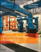
Nonhosted sprinkler families must have the Offset height parameter set to locate the heads at the proper elevation (see Figure 16-5).
Figure 16-5: Nonhosted sprinkler heads
Upright sprinkler heads are normally nonhosted because they are located in spaces that do not have ceilings, such as storage rooms or mechanical closets. If you do not set the offset height, the heads will come in at a default of 0′, which could locate the heads on or below the floor level. This is easily fixed by clicking the button to place a sprinkler and changing the Offset setting in the Properties palette before placing the family.
Creating Fire Protection Systems
There are several options for the types of fire protection systems that can be created. They are as follows:
Fire Protection This can be used for the building sprinkler piping, or it can be used for the utility fire protection coming into your building to connect the base of your fire protection riser.
Wet Fire Protection This pipe system type normally is used for the layout of the piping from the riser to the sprinkler head when freezing is not expected.
Dry Fire Protection This pipe system type normally is used for the layout of the piping from the riser to the sprinkler head when there is potential for damage from freezing.
Preaction This pipe system can also be used for a deluge system.
Fire Protection Other This pipe system can be used for a glycol antifreeze system, and it can also be used for a chemical suppression system.
You can also refer to piping systems in Chapter 11, “Mechanical Piping” for more information. When creating a fire protection system, one thing to remember is that the system will not calculate and autosize as will domestic water systems. The main reason is that fire protection systems have no true way of selecting and calculating which heads are in the highest demand.
Strength in Numbers
John’s employer has just come back from a meeting with a high-profile client and has sold their company’s ability to produce a fire protection model in BIM. His employer has stated that the client wants to see the total of flow for the highest demand on the system so that their building can pass the fire inspection requirements as mandated by the local fire marshal. John has already calculated the system load, so he knows where the highest demand will be located. John decides that the easiest way to accomplish this is to set the Comments parameter to calc-gpm for the sprinkler heads and then filter these heads through a schedule with a grand total of Gallons Per Minute. The inspector reviewed the schedule and approved the client’s building, and the client was satisfied.
To replicate what John did, you can do the following:
1. Select the sprinkler heads that need to be modified, and set the Comments parameter to calc-gpm.

2. Go to the View or Analyze tab on the ribbon, and then select Schedule/Quantities. The Schedule dialog box opens. Select Sprinklers from the Category group, and then select OK.

3. From the Available Fields dialog box, select the parameters Flow and Comments, and add them to the Schedule Fields (In Order) dialog box. Then click OK, which creates your schedule.

4. Now that you have the sprinkler schedule, you want to total only the sprinklers with comments. To do this, there are several parameters you have to set:
a. From the Properties Browser, select the Filter tab and then change the filter to Comments.
b. Set the Equals parameter to calc-gpm.
c. Select Sorting/Grouping, and change the Sort By pull-down menu to Comments.
d. Select Itemize Every Instance.
e. Select the check box Grand Totals and change the drop-down menu to Totals Only.
f. Select the Formatting tab, highlight Flow, and select the Calculate Totals check box. Next, highlight Comments, and select Hidden Fields.
Now your schedule will show only the items you want to show up, including the total GPM flow.

If the system were to try to calculate by GPM, it would account for every sprinkler head on the system, which would grossly oversize the system. Also, the fire protection system at this time has no effective way of calculating the water pressure as it goes higher in elevation.
Creating a Fire Protection Wet System
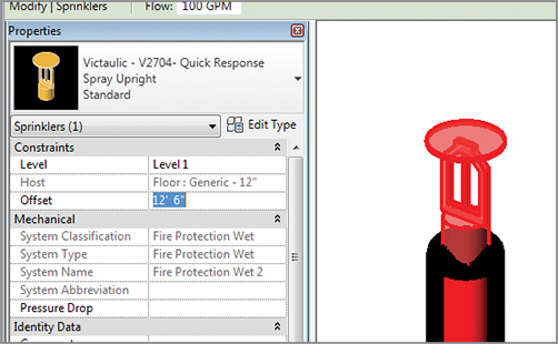
When creating a fire protection wet system or one of the systems previously mentioned, you would first select all the components that are going to be associated with that system. Selecting these items may be easier if you use the Temporary Hide/Isolate command to hide those model categories that you do not want to include (see Figure 16-6).
Figure 16-6: Adding sprinkler heads to a system
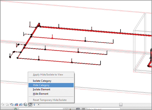
In case a system has already been started, you can add to the system by selecting a component on the system. Click Piping Systems Edit System Add To System, and then window all the items you want to add to the system. If this is done correctly, you should see all the items in the System Browser under the system you created (see Figure 16-7).
Figure 16-7: Fire protection system in the System Browser
Filtering Fire Protection Systems
Once your fire protection system is created, you will need to make sure the piping will filter correctly. Using filters to assign colors and line types to piping will help keep your systems organized. To create a fire protection filter, do the following:
1. On the View tab, select Graphics Filters. The default keyboard shortcut VG will take you to the same location.
2. Click Edit/New. The Filter Settings dialog box opens. You should notice that there are a number of filters already created. Select the Domestic Hot Water filter, right-click, and select Duplicate. Right-click again, and rename the filter to the type of piping system you are filtering. In the right corner, you will see a dialog box named Filtering Rules.
a. If you want all fire protection systems in your project to be displayed the same, keep the Filter By parameter set to System Classification. The filter rules should be set to Contains, and the data required is Fire Protection. Make sure that you correctly capitalize all words in the text field.
b. If you want to have the option to change the display of various types of fire protection systems within your project, change the rule from System Classification to System Name. The filter rules should be set to Equals, and the text field must match your system name exactly (see Figure 16-8).
Figure 16-8: Filtering by system name

3. Rename Domestic Hot Water 1 to Fire Protection (or whatever you named your system), click Apply, and close. Now you will see the Visibility/Graphic dialog box with the Filters tab. Click Add, and you should see the newly created filter (see Figure 16-9).
Figure 16-9: Using your filter to override the graphic display

Name Filters and Systems the Same
Always remember to name your filter exactly the way you named your system because filters are case sensitive. Incorrect naming due to misspellings or incorrect case are two of the main reasons for filters not working.
Deciding what colors and line types you want for the fire protection system will most likely come from existing CAD standards. Once the filters are created and applied to the views, save them as view templates and load them into the main templates. This will add to the ease of completing a design in an efficient manner.
Using Mechanical Joint Fittings
So what do you do if you require special fittings? It’s quite common to see mechanical joints required on fire protection systems. Because they do not exist in the out-of-box content of Revit MEP 2012, you are stuck with three choices:
- First, you can use regular fittings and then copy and rename them to the type of fittings you need, as was demonstrated for the fire pump. Then you can use schedules to count the number and make of the fittings.
- Second, you could create your own custom fittings. This requires that you have enough time and money to create every fitting you need. If you can afford it, this option is worth the investment in the long haul.
- Third is to find a manufacturer that has already developed their content. Victaulic has most, if not all, of their products in Revit on its website at www.victaulic.com. You can download them and load the fittings you need for your layout. No matter the source of your content, always take the time to test it to ensure that it works the way it should. Manufacturers who are starting to produce Revit content are looking to the industry for guidance. If you find something that doesn’t work, let the manufacturer know.
Copying the Lookup Tables
When downloading or developing your own fittings, be sure to copy the lookup tables into the lookup table folder called for by the revit.ini file. If you don’t do this, the automatic adjustment of fittings may not work properly.
Fire Protection Pipe Settings and Routing
Now you are nearly ready to route piping. There are still a number of pipe settings that will help you. Pipe Systems and Pipe Types settings will be important to adjust. Pipe material, the pipe sizing table, and the fluids table can also be altered as needed. These were explained previously in Chapter 11, “Mechanical Piping.”
The various options for automatic and manual pipe routing were also discussed in Chapter 11. Unlike mechanical piping or domestic and sanitary piping, automatic pipe routing is more likely to be a productive option. Fire protection piping is often much more symmetrical than piping in other disciplines, making the autorouting easier to manage. Refer to Chapter 11 to review both auto and manual pipe routing.
Place fire protection equipment. When starting a fire protection model, placing the equipment can make or break your design. The ability of Revit to verify your layouts early through the coordination of this equipment with other disciplines can set the pace for a successful project.
Master It What method can be used to help speed up production when using a standard fire riser on multiple buildings?
Create fire protection systems. Creating proper fire protection systems is essential to the performance and behavior of the fire protection model. Properly created fire protection systems also help with being able to coordinate with other disciplines during design.
Master It Marty has just created a fire protection system name called Wet1, and he has created a filter system type named wet1. Now Marty is in a presentation, and his system is not filtering properly. What should he look at first? What should he do if there is a second problem?
Route fire protection piping. Fire protection piping can be routed by a couple of methods. It can be set up with different materials to help with takeoffs and specifications. Once piping has been routed, it can be coordinated with other disciplines to reduce errors and omissions.
Master It What are some of the methods to deal with fittings that may not be supplied with Revit MEP 2012?