Chapter 15
Plumbing (Domestic, Sanitary, and Other Piping)
Routing plumbing piping has come a long way from drawing circles and lines on paper. Over the past 30 years, tools such as the straight edge, 30/60 triangles, and the Timely template have been replaced by CAD systems. With more owners requiring BIM, a plumbing designer has to become a virtual pipe installer. Instead of just drawing circles and lines, you have to understand more about how fittings go together to construct your piping design. This is where Revit MEP excels; it can help you create your designs more accurately and efficiently.
In this chapter, you will learn to do the following:
- Customize out-of-the-box Revit plumbing fixtures for scheduling purposes
- Use custom plumbing pipe assemblies to increase speed and efficiency in plumbing layouts
- Adjust the plumbing pipe settings
- Select the best pipe routing options for your project
- Adjust pipe fittings
- Adjust the visibility of pipes
Working with Plumbing Fixtures
Plumbing fixtures are as important to the look of an architectural design as granite countertops or marble tile. Plumbing fixtures, when properly selected, will not only enhance the visual design but will also promote cleanliness and hygiene. Plumbing fixtures normally are placed by the architect during schematic design to coordinate usability and meet the requirements of governing codes.
From a plumbing design point of view, different criteria must be examined. What are the water conservation guidelines? Are the plumbing fixtures required to meet LEED standards? Other questions should be asked during design: Will you as the designer want to use the same plumbing fixtures that the architect’s model uses to connect to your piping, or will you substitute your company’s standard fixtures? If so, do you need to apply shared parameters that reflect the design standards required? For example, in the United States there are two major plumbing codes: the Uniform Plumbing Code and the International Plumbing Code. To complicate matters further, some states will adopt one of these two codes and then add their own amendments, creating their own state code.
With Revit MEP 2012, you can apply this information through the use of parameters. This can be done in a couple of ways. First, you can edit the information in the family itself by selecting a plumbing fixture family and editing the information through the Type Properties dialog box (see Figure 15-1).
Figure 15-1: Editing the type properties

The second way to edit the information is to create a type catalog. Using type catalogs enables the user to easily produce more information about different types or models of the same family. For example, most manufacturers of bathrooms use model numbers to show the differences in finishes, rough-in locations, handle locations, and handicap accessibility information. Also, type catalogs allow the plumbing design to be easily changed from one manufacturer to another.
The easiest way to create a type catalog is to first open a plumbing fixture family and then review and make note of the type properties you want to be able to modify. Then create a TXT file that will populate the information. To create this TXT file, do the following:
1. Open Microsoft Excel. (If you do not have Excel, you can use Notepad or OpenOffice.org to achieve to same goal. OpenOffice.org can be downloaded from www.openOffice.org.) Save the spreadsheet as a comma-separated values (CSV) file, making sure to name it using the plumbing fixture’s family name.
2. Now leave cell A1 blank. This is necessary for the type name of the family, such as Kohler or American Standard, to be listed in column A properly.
3. Next you will add the parameter name followed by the parameter unit in row 1. For this example, you will be using the following system parameters from the identity data located in the plumbing fixture family:
| Keynote | Keynote##other## |
| Model | Model##other## |
| Manufacturer | Manufacturer##other## |
| Type Comments | Type Comments##other## |
| URL | URL##other## |
| Description | Description##other## |
4. Add the information for each row that you want to be able to schedule (see Figure 15-2).
Figure 15-2: Creating a CSV file for type catalogs

5. Once everything has been input, save the file. Make sure that when the file is created, it is located in the same directory as the family it references.
6. Next, go to the directory where you saved your file, and rename the extension from .csv to .txt. To review what the TXT file looks like or to make quick edits without converting back to a CSV file, you can open this file with Notepad (see Figure 15-3).
Figure 15-3: Opening the TXT file in Notepad

If you created your file properly, you should see a catalog of information when inserting the family (see Figure 15-4).
Figure 15-4: Type catalog

Type Catalog References
Type catalogs can be referenced by using system parameters and shared parameters. The following list contains some of the types of parameters and parameter units that can be used in creating a type catalog TXT file:
Text parameter name##OTHER##
Integer parameter name##OTHER##
Number parameter name##OTHER##
Length parameter name##LENGTH##FEET
Area parameter name##AREA##SQUARE_FEET
Volume parameter name##VOLUME##CUBIC_FEET
Angle parameter name##ANGLE##DEGREES
Slope parameter name##SLOPE##SLOPE_DEGREES
Currency parameter name##CURRENCY##
URL parameter name##OTHER##
Material parameter name##OTHER##
Yes/No parameter name##OTHER##
<Family Type> parameter name##OTHER##
One thing to note is that the parameter must exist in the family in order to contain the data before the type catalog can insert the desired values.
Now that you have information added to your plumbing fixture family and you have placed the plumbing fixtures into the plan, you will want to schedule that information.
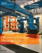
To accomplish this, go to the Analyze or View tab on the ribbon, and then select Schedule/Quantities. This opens the New Schedule dialog box. Select Plumbing Fixtures from the Category group, and then click OK (see Figure 15-5).
Figure 15-5: Select Plumbing Fixtures from the Category group
Next, select the information from the Available Fields dialog box and add it to the Schedule fields (in order) dialog box. Then click OK, which will create your schedule (see Figure 15-6).
Figure 15-6: Plumbing Fixture schedule

Now that you have the Plumbing Fixture Schedule created, you may not want to see duplicate information or blank information, so you will need to sort the information. To do this, go to the Properties palette, select Sorting/Grouping, change the Sort By option to Type Mark, and then deselect the Itemize Every Instance check box. Now your schedule will show only the items that have information (see Figure 15-7). For more information on customizing the appearance and content of schedules, see Chapter 7, “Schedules.”
Figure 15-7: Sorted schedule

Working with Architectural Linked-in Plumbing Models
When using Revit MEP for plumbing, there are two main options for coordinating plumbing fixtures between architectural linked-in models and plumbing models. The first option is to manually place the plumbing designer’s edited plumbing fixtures over the architectural plumbing fixtures. The second option is to use the Copy/Monitor feature.
Using the Copy/Monitor feature will place either an exact copy of the architect’s fixture family or allow you to select your family instead. This option allows you to use a family that has already been edited with proper connectors and scheduling information. Anytime your fixture family is not graphically equal to those shown in the architect’s file, you will need to hide the architect’s fixtures in your printing views.
With either method, you will have to take care that your fixtures remain coordinated with any architectural plan changes. If you have placed your families manually, you will have to check locations visually. If you have used the Copy/Monitor function, Revit will notify you that there has been a change via the Collaborate ribbon tab Coordination Review. Also, the Copy/Monitor feature does not automatically update to show any new fixtures that the architect may have added. We’ll talk more about this later in the chapter.
With either of the options, you can use plumbing fixture families that represent only the piping portion of each fixture. These custom pipe assemblies are fittings preassembled or modeled to line up in the locations of the linked architectural plumbing fixtures. These are created as plumbing fixture families.
Create Custom Pipe Assemblies
Custom pipe assemblies can be represented in one of two ways in the Family Editor. First, you can use sweeps to represent the p-trap, wye, and associated piping. This method creates a smaller file size and reduces the size of the overall plumbing model but is not as accurate for quantity takeoffs (see Figure 15-8).
Figure 15-8: Representation of a pipe assembly created with sweeps

The second method is to assemble nested families, which can allow for better quantity takeoffs for all the fittings, create more-accurate dimensional information when supplied by manufacturers, and can be easier for the plumbing designer to create. The downside is that it will produce a larger family file. This second option will help you achieve more of the building information modeling status while helping to increase productivity (see Figure 15-9).
Figure 15-9: Nested pipe assembly

Now let’s examine how nested piping assemblies are put together and some key areas to be mindful of:
1. Open the PR-Sinks and Lavs.rfa file found at www.sybex.com/go/masteringrevitmep2012.
2. Several modified pipe fitting families are nested into this family that make up the assembly. They are Trap P - PVC-DWV.rfa, Tee Sanitary-PVC-DWV.rfa, PVC-DWV Pipe Section.rfa, Plug-PVC-DWV.rfa, Elbow -Copper Type L.rfa, and Copper Type L Pipe Section.rfa. These can all be found at www.sybex.com/go/masteringrevitmep2012, or you can get the originals from the Pipe Fitting directory located in the imperial library.
3. When placing the fittings together, make sure to align, lock, and dimension each fitting together. If not, the fittings will pull apart (see Figure 15-10).
Figure 15-10: Aligning, locking, and dimensioning to lock nested families down

4. When creating your pipe assembly, make sure that the Center Front/Back reference plane is located where the finish face of the wall will be located in the project. By doing this, the family will easily “snap” into place.
Plumbing Fixture Families Are Not Created Equal
Plumbing fixture families are not always created equal. Rather than starting the family modeling front facing the front, some modelers will just model in whatever view is available. This has always been a problem in Revit and, as more families become available, the issue will increase. This can cause a few problems when aligning your fixture family to the Architect’s or when replacing one fixture with another.
As your skills grow and you start creating your own content, please remember simple modeling etiquette. The model should be modeled in the proper orientation. The Front, Back, Top, Bottom, Left, and Right views should match the orientation of the product being modeled. This will increase productivity when aligning other items such as pipe assemblies under plumbing fixtures.
Various examples of both simple and complex plumbing fixture families can be downloaded from Autodesk User Group International (www.augi.com) and the Autodesk University website (http://au.autodesk.com).
5. You can add parameters to flex your piping to align it under a sink or lavatory or to give a certain depth to account for a floor slab. You can make these parameters as complex or as simple as you want (see Figure 15-11).
Figure 15-11: Using parameters to flex the piping assembly

6. Make sure that when adding a water piping connection to a rough-in pipe, you add an elbow pointing in the direction of the pipe routing (for example, from the floor or from the ceiling). This will help with autorouting and manual routing (see Figure 15-12).
Figure 15-12: Adding a simple elbow pointed toward the direction of flow

Now that you have reviewed some of the items that make up a pipe assembly, you can place the pipe assembly family in your plumbing model and align it with the architectural plumbing fixtures without having to turn them off. If the architect adds a plumbing fixture, you now have the capability to view the added fixture. By following this workflow, you can both tag and schedule the pipe assembly family while the graphic representation needs are satisfied by the family in the architectural link file.
Copy/Monitor Plumbing Fixtures
Now let’s take it a step further. If the plumbing fixtures that the architects are using match the same orientation of your pipe assemblies, you can copy/monitor the pipe assemblies directly behind the plumbing fixtures. Then, when the architect moves a plumbing fixture, you will receive a warning that you need to coordinate your view. You will also have the capability to copy and change all of the plumbing fixtures on multiple levels at one time. This can be a huge time-saver.
To use Copy/Monitor, do the following:
1. Choose Collaborate Copy/Monitor, and then select Current Link.
2. In the Copy/Monitor panel, select Batch Copy. Click Specify Type Mapping Behavior & Copy Fixtures. Once you click this button, you will be taken to a Coordination panel that has Category and Behavior selection tables.
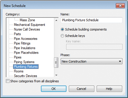
3. Select Type Mapping, and replace the plumbing fixtures from the architect with the ones you created (see Figure 15-13).
Figure 15-13: Type mapping
4. Next, click Copy and then select the plumbing fixtures you want to copy (see Figure 15-14).
Figure 15-14: Copying and replacing fixture types

5. If you are working on multiple floors, you can select all levels from the elevations view and then filter and select only the plumbing fixtures. Then click Finish.
If you highlight the assembly, you should see the monitoring symbol on the assembly (see Figure 15-15).
Figure 15-15: Monitoring symbol shown on the assembly

To take full advantage of the Copy/Monitor feature, you will need to coordinate all of your plumbing fixtures with your pipe assemblies, but you will find it is time well spent.
Choosing Pipe Settings and Pipe Routing Options
When setting up piping to route, you will want to apply the proper pipe material so that quantity takeoffs can be easily scheduled. There are several areas you will have to adjust to set this up properly. Most important are Piping Systems and Pipe Types settings. These and other piping parameters are discussed at length in Chapter 11, “Mechanical Piping.” Also covered in that chapter are the two routing options, auto and manual. Here you will examine the options available for sloped piping.
Sloping Pipe
When modeling pipe, you can use either the autorouting or the manual routing feature. Especially when applied to sloped pipe, you are more likely to have success with a manual layout.
For sloping pipe to work properly, it needs to have start and end points. To set up sloping pipe, open Ch15_plumbing.rvt and Ch15_base.rvt. Also download sanitary point of connection.rfa and wall cleanout.rfa. All of these files are found at www.sybex.com/go/masteringrevitmep2012. Next, do the following:
1. Make sure that you have your view range set correctly, because you are going to be routing pipes below 0′-0″. Select View Range from the Properties palette, and change Bottom and View Depth to Unlimited for your lowest floor views (see Figure 15-16). A good starting point for upper-floor view ranges is –3′-0″. (This setting will vary according to your project.)
Figure 15-16: View Range settings

2. Look at your routing choices for your main. Then locate your end run fixture, floor cleanout, or wall cleanout.
3. Locate your sanitary point of connection outside the building. Locate the sanitary piping at –4′-0″ below the finished floor.
4. Select the Pipe toolbar located on the Home tab of the ribbon. Before you start routing your pipe, be sure to set the 1/8″/12″ slope setting, and make sure you have the justification set to your preference.

5. Start your run from the sanitary point of connection, and route into your last fixture or cleanout. You now have a main trunk off of which you can build your system.
Sloped Pipe Systems Are Like Trees
When you are routing sloped pipe systems, think about sketching a tree—starting from the base of the tree, and then working from the base to the branches, and then from the branches to the leaves or, in this case, a water closet. The secret to successfully modeling sloped pipe is to draw your piping from the main first.
6. Select the Pipe toolbar, and then select the point on the main from which you want to route. After starting your pipe run, you can either select the Inherit Elevation and Inherit Size buttons from the toolbar or press the spacebar one time. This makes the new piping connect at the same elevation and size as the pipe main you selected to start the run. Then route out to the water closets or any other components that take 1/8″ slope.


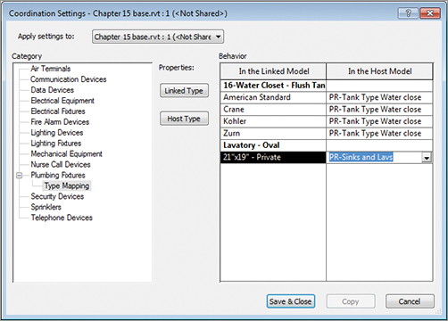
7. Route all of your sloped pipe that contains the same degree of slope first. Then route all of the next matching slope. Having a redundant pattern will add to your efficiency and productivity. Now you should have a sloped system (see Figure 15-17).
Figure 15-17: Sanitary layout with sloped piping
Annotating Invert Elevation and Slope
Once your piping model is at the desired slope and elevation, you can easily apply parametric elevation and slope annotations. Choose Annotate Dimension Spot Slope or Spot Elevation. The slope tag is very simple; it can be placed at any point along a pipe run, while viewing single- or double-line pipe.
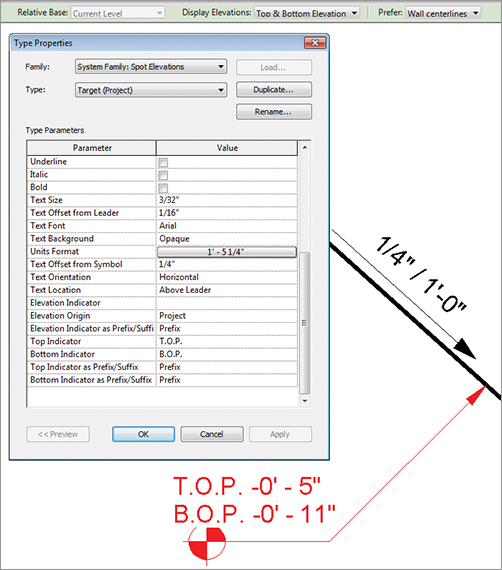
The elevation tag is more complicated. The Spot Elevation tag will be able to show only the top and/or bottom elevation of the pipe selected. You must be able to see double-line pipe (Fine Detail) in order to place the Spot Elevation. This tag exists only within the project. It is a system family, and it cannot be edited in the Family Editor. This means that all changes are done in the Properties and Type Properties palettes within the project interface. In the Options Bar, you will want to make sure to set the elevation to reference the correct level. Also in the Options Bar, you should set the Display Elevations option to either Bottom Elevation or Top And Bottom Elevation. In the Type Properties dialog box, you will likely want to change the Units Format and the Top and Bottom indicators to match your standard for labeling pipe elevation, for example, B.O.P. = bottom of pipe (see Figure 15-18).
Figure 15-18: Customizing the Spot Elevation tag
If you prefer to annotate the elevation of the pipe center line, you will have to use a pipe tag. This is the same type of annotation family as the common pipe diameter tag. You can duplicate and edit that family to change the label to include the parameters Start Offset and End Offset. Note that these parameters can display the elevations of only the two endpoints of each pipe segment. Like the Spot Elevation tag, they cannot display the elevation at any point along the pipe segment.
Without fittings, piping would not be worth a whole lot. Fittings help shut off, regulate, open up, and, most important, they save lives. In Revit, most fitting families have the following functions:
End Cap These can be placed only at the end of pipe.
Tee, Tap, Wye, or Cross These can be placed anywhere along pipe runs.
Transitions, Couplings, or Unions These can be placed only at the end of pipe. They are used to join a smaller, larger, or same-size pipe.
Flange These can be placed at the end of pipe or face to face with another flange.
Using Pipe Fitting Controls
Understanding pipe fitting controls can really make life easier if you are routing a lot of piping. When you are laying out your piping, turn 90 degrees to create an elbow. If you click the elbow, you will notice a plus (+) sign. If you click that sign, it will change from an elbow to a tee, allowing you to add more piping and to continue your pipe routing. If you select the minus (–) sign, it will downgrade the fitting. When you see the ![]() symbol on a fitting, it allows you to rotate the fitting, and the
symbol on a fitting, it allows you to rotate the fitting, and the ![]() symbol allows you to flip the fitting.
symbol allows you to flip the fitting.
Placing Valves
When you need to add valves to your piping, select the Home tab and click Pipe Accessories. Use the Type Selector to select the type of valve you want to use. Most valves will break into the piping and connect by simply selecting a piece of pipe (see Figure 15-19).
Figure 15-19: A fitting breaks into the piping system

A Fitting End
In early 2008, an AEC firm from Knoxville, Tennessee was working on a hotel project in Pigeon Forge, Tennessee. It was the first hotel produced in Revit for this firm. This 90-room hotel had already gone over the estimated projected design hours because of constant changes of field conditions.
The building used conventional sanitary plumbing with traditional multiple vent stacks. The project went out for bid, and when the bids came back, the building was slightly over the estimated budget. The design team was asked to figure a way to reduce the costs back to the budgeted amount. After carefully reviewing the project, the plumbing designer and engineer decided to use a PVC version of a So-Vent plumbing system. Only two families would have to be created for Revit: an Aerator and a De-aerator fitting. The cast-iron version of the system has been successfully used in northern parts of the United States in high-rise design for years.
The problem the plumbing designer faced with using such a system was that no one had installed one in east Tennessee. Plumbing code officials had never seen the system installed, and they stated it did not meet traditional methods of vent design. By using a section under codes that allowed for the use of engineered plumbing systems, the design team proceeded to design the system. Because the existing layout was already in Revit, using it to redesign the system was the logical choice.
Within two working days, the model and contract documents were revised with the new layout, which was then rebid. The cost of the vent system was reduced by one-third, which led to fewer holes being cut, fewer man-hours, and reduced fire-stopping costs. Because the plumbing contractor had never before installed a So-Vent system, being able to use printouts of the 3D model helped speed up the installation of the system and ensure that it was installed properly.

Although the project may have lost money for the firm, the hotel owner was happy knowing that his construction costs were within budget and that his hotel could open on time.
Now that you have created systems and added the piping, you need to be able to display them in different views. You may also want them to display with different colors and line weights. If you created your systems correctly, you can go to Filters located on the View tab. Here you are able to create new filters by duplicating and modifying any of the existing ones (see Figure 15-20).
Figure 15-20: Modifying the filter settings

Once the filters have been created, go into each view where you want the different disciplines to show up and type VG to bring up the Visibility/Graphic Overrides dialog box. Click the Filters tab, and add the newly created filters. At this point, you can control the line types, colors, and patterns of the filtered objects to match your company standards (see Figure 15-21).
Figure 15-21: Adjusting colors and line types through Visibility/Graphic Overrides

Now that your plans are coordinated and displaying the way you require, you are well on your way to completing your documentation. Also consider using the same filters to display 3D views that can enhance the design, making it easier to understand, and further reducing errors (see Figure 15-22).
Figure 15-22: Color-coded 3D views for review

One common drafting standard is to show all piping serving a given floor in the same view. For instance, on the sheet showing the restroom located on the second floor of a three-story building, you would expect to see all the sanitary piping below the second floor and the vent piping in the second-floor attic serving that restroom. You would not want to see the sanitary pipe serving the third-floor restroom, even though it also occupies the second-floor attic, and you would not want to see the vent piping serving the first floor.
One way to accomplish this selective visibility in projects with overlapping view ranges is with workset visibility. You can assign all the piping serving the first, second, and third floors to specific first-, second-, and third-floor worksets. This will allow you to turn off the first- and third-floor worksets, cleaning up your second-floor view. See Chapter 3, “Worksets and Worksharing,” for more information.
Customize out-of-the-box Revit plumbing fixtures for scheduling purposes. Learning how to customize existing plumbing fixtures can help with productivity and provide more-robust building information.
Master It What are the two types of parameter information that can be scheduled and used in type catalogs?
Use custom plumbing pipe assemblies to increase speed and efficiency in plumbing layouts. Sometimes you are required to think outside the box and learn how to use new tools to get the most benefit out of them. By utilizing the new Copy/Monitor feature when creating custom pipe assemblies, you can take production to the next level.
Master It Why are nested pipe assembly families better to use than the modeled pipe assembly for a BIM project?
Adjust the plumbing pipe settings. Pipe settings are crucial to the ability to have Revit MEP model your plumbing layout, the way it will look, and the way it will perform.
Master It Do fitting parameters have to be set up in the system pipe types?
Select the best pipe routing options for your project. When using Revit MEP 2012 for your plumbing layouts, you must understand the functions of automatic pipe routing, manual pipe routing, and sloping pipe. Once these functions are mastered, you can lay out any type of piping system.
Master It A plumbing designer has just been asked to lay out a sloped plumbing system and has only a day to pipe up a clubhouse. Where should the designer start the pipe route?
Adjust pipe fittings. Pipe fittings are needed in systems to make the systems function properly and to produce documentation for construction. Being able to add or modify fittings can increase productivity.
Master It You have just finished your modeled layout and given it to your employer for review. Your boss asks you to remove a couple of elbows and replace them with tees for future expansion. What would be your method to accomplish this quickly?
Adjust the visibility of pipes. Being able to adjust the visibility gives the plumbing designer or user the ability to set up multiple views and control the graphics for documentation.
Master It There are too many systems showing up in your views. What would you do to show only one piping system in that view?