
2
Hands-On with M5Stack Units
You learned about the inner electronics of the M5Stack Core in Chapter 1. You also learned about UI design basics and received overview information on the UIFlow Blockly coding software. The new knowledge obtained in the previous chapter will allow you to learn about and use M5Stack units for creating interactive and engaging electronic devices.
In this chapter, you will explore M5Stack units for control and detection applications. The units are small electronic circuits such as an infrared (IR) remote, an angle sensor, an RGB LED, and a passive motion sensor. We will use the UIFlow Blockly code to investigate the function of the extendable electronic units.
By the end of this chapter, you will be able to perform the following technical tasks with M5Stack units:
- Draw a typical M5Stack unit connector electrical pinout
- Code an RGB LED unit UIFlow test application
- Code an IR remote unit UIFlow test application
- Code an angle sensor unit UIFlow test application
- Code a motion sensor unit UIFlow test application
In this chapter, we’re going to cover the following main topics:
- Introducing M5Stack units
- Interacting with an RGB LED unit
- Interacting with an IR remote unit
- Interacting with an angle sensor unit
- Interacting with a motion sensor unit
Technical requirements
To engage with the chapter’s learning content, you will need the M5GO IoT starter kit to explore the internal/external hardware electronics and software coding of your first basic application. The UIFlow code block software will be required to build and run the M5Stack Core application.
You will require the following:
- M5Burner software
- The M5Stack Core controller
- The M5GO IoT starter kit
- UIFlow code block software
- A USB C cable
Here is the GitHub repository for software resources: https://github.com/PacktPublishing/M5Stack-Electronic-Blueprints/tree/main/Chapter02
Introducing M5Stack units
The M5Stack unit is a small electronic input sensor or electrical output device that extends the interactive use of the M5Stack Core. There is a variety of units to select from to create a multitude of wearable and control applications. You can select from input units or output units. Input units take physical stimuli such as light or sound to create engaging detection devices. Output units such as RGB LEDs or buzzers provide visual and audio effects to your M5Stack Core creations. Examples of M5Stack units are shown in Figure 2.1:
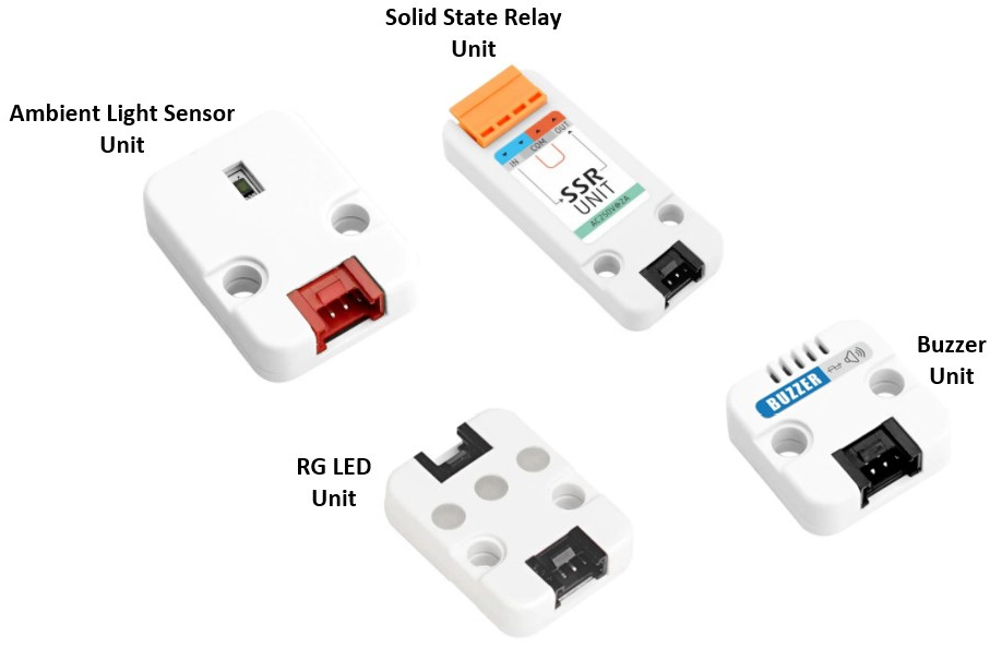
Figure 2.1 – Examples of M5Stack units
You attach the unit using a small jumper wire and mate it to the appropriate port. The M5Stack Core has three ports. The ports are labeled A, B, and C. The following figure shows the three ports of the M5Stack Core:
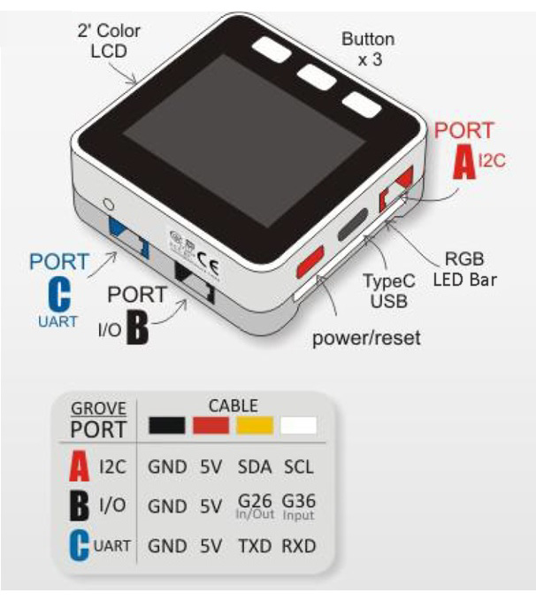
Figure 2.2 – M5Stack Core ports
You can use port A to handle basic digital input/output units along with inter-integrated circuits or I2C communications. Like port A, you can use port B with basic digital input/output units. You can use port C to communicate with other serial units, such as the unit CAM shown in Figure 2.3:
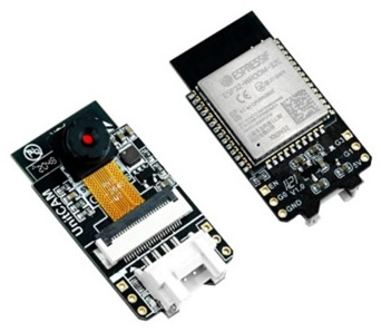
Figure 2.3 – Port C – Unit CAM application
As you can see, each individual port has four pins. All ports have a 5V and GND pin. The other two pins are specialized for each port. You select the unit based on the M5Stack Core application and the approach in which the unit works with the port’s specialized pins. You can then create your own personal unit to perform the control or sensor task designed for the intended unique application. You can easily draw an electronic circuit schematic diagram showing your personalized unit wired to the M5Stack Core’s electrical pinout. Figure 2.4 shows an example electronic circuit schematic of personalized wiring for a push button switch:
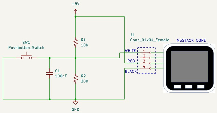
Figure 2.4 – Port B personalized wiring for a pushbutton switch
Now that you have learned about the various M5 Stack Core ports that allow different units to operate properly, you will build an RGB LED light using an RGB unit, a small jumper harness, and an M5Stack Core in the next section.
Interacting with an RGB LED unit
The RGB LED unit has three individual LEDs: red, green, and blue emitters. You can control each LED individually or simultaneously using code. You can also control the RGB LED unit’s intensity. With the M5Stack Core, you can create visually appealing light effects using the RGB LED unit. Figure 2.5 shows the RGB LED unit. To program the RGB LED, you will use the UIFlow Blockly code software discussed in Chapter 1.
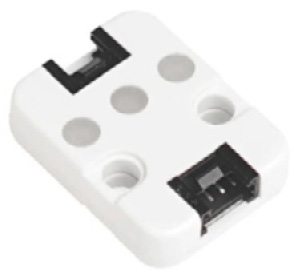
Figure 2.5 – The RGB LED unit
The RGB LED unit consists of three individual pixels consisting of red, green, and blue colors. Each pixel is operated by an electronic control circuit. The colored pixels and electronic control circuit are packaged inside an RGB chip. The RGB chip is a surface mount device (SMD) of the 5050 variant component footprint. The footprint is the mechanical package of the electronic SMD device. You can see a picture and mechanical package dimensions of the RGB chip in Figure 2.6. The RGB chip’s part number is SK6812:
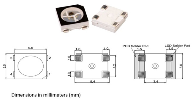
Figure 2.6 – The SK6812 RGB chip and its mechanical package dimensions
To operate the RGB LED unit, you will attach the programmable device to the M5Stack Core using a four-wire jumper harness. You will use port B of the M5Stack Core to attach the RGB LED unit to the M5Stack Core. Figure 2.7 shows the attachment of the four-wire jumper harness between the RGB LED unit and the M5Stack Core. The four-wire jumper harness has a color code scheme consisting of black, red, white, and yellow. You can verify that the jumper harness is correctly attached between the M5Stack Core and the RGB LED unit by the black wire located on the left side:
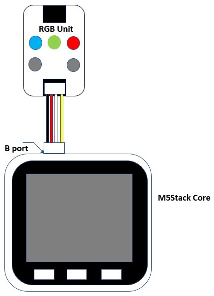
Figure 2.7 – Attaching the M5Stack Core to the RGB LED unit
You are now ready to program the RGB LED unit attached to the M5Stack Core using the UIFlow Blockly code software.
Programming the M5Stack Core to operate the RGB LED unit
You will use the UIFlow Blockly code software to program the M5Stack Core to operate the RGB LED unit. You will take a USB C cable and insert it into the M5Stack Core’s equivalent port. The following figure illustrates the location and insertion of the USB C cable into the M5Stack Core:
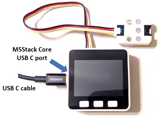
Figure 2.8 – Inserting a USB C cable into the M5Stack Core USB C port
You will take the other end of the USB C cable and insert it into your UIFlow Blockly code development machine. Your M5Stack Core should be turned on. You will press the middle button to configure your M5Stack Core to be in USB mode. Figure 2.9 shows the M5Stack Core operating in USB mode.
Note
Refer to Chapter 1 to configure the programmable controller for USB mode.
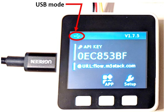
Figure 2.9 – The M5Stack Core operating in USB mode
You will then select from the appropriate Blockly code blocks bin to build the RGB LED unit application shown in Figure 2.10:
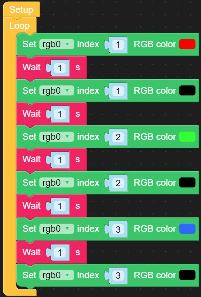
Figure 2.10 – RGB LED unit example UIFlow Blockly code
Note
The RGB LED unit needs to be selected so the programming blocks will be available for use in your application. At the lower left side of the UI layout, click the plus (+) sign with your mouse. Select the RGB LED unit to have access to the device’s programming properties.
You will design the M5Stack Core’s UI to display the text RGB example on the LCD. You will configure the UI text properties as shown in Figure 2.11:
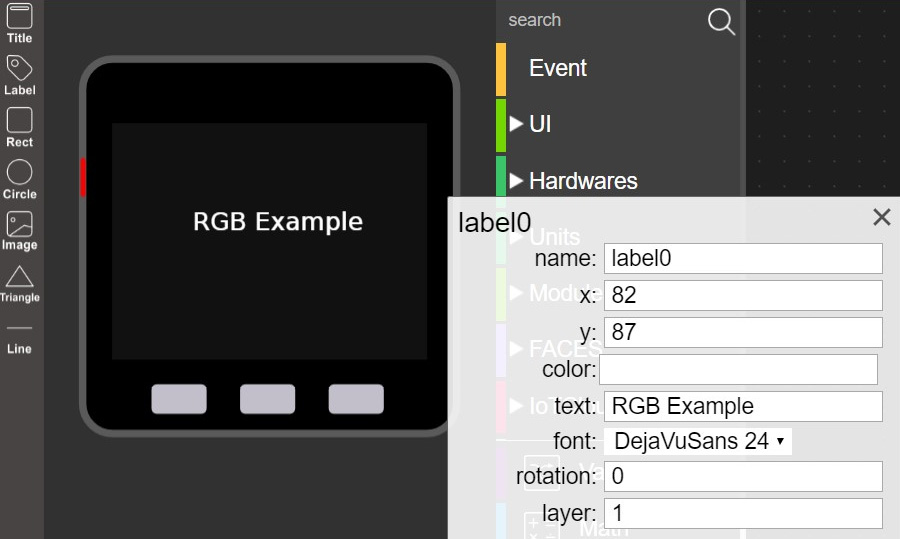
Figure 2.11 – The M5Stack Core’s RGB LED UI display
You can run the RGB LED UI example by clicking the Run button with your mouse:

Figure 2.12 – Executing the RGB LED UI example with the Run button
The Blockly code will run immediately on your M5Stack Core. Figure 2.13 shows the green LED operating on the M5Stack Core. There is a 1-second delay between the M5Stack Core changing between the red, green, and blue LEDs. As a test, change the delay time to 500 milliseconds (ms) and observe the turn-on/off speeds of the LEDs.
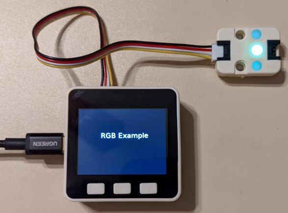
Figure 2.13 – The green LED turned on by the M5Stack Core
Interactive quiz 1
After changing the Wait block from 1 sec to 0.5 sec, did the RGB LEDs turn on slower or faster?
An interactive RGB LED unit
You can make the RGB LED unit interactive by pressing the A and B pushbuttons on the M5Stack Core. You will program the M5Stack Core A button to allow the red, green, and blue LEDs to turn on sequentially. You will program each color LED to turn on 500 ms. Conversely, you will program the B button to turn off the red, green, and blue LEDs. You will use the Blockly code program shown in Figure 2.14:
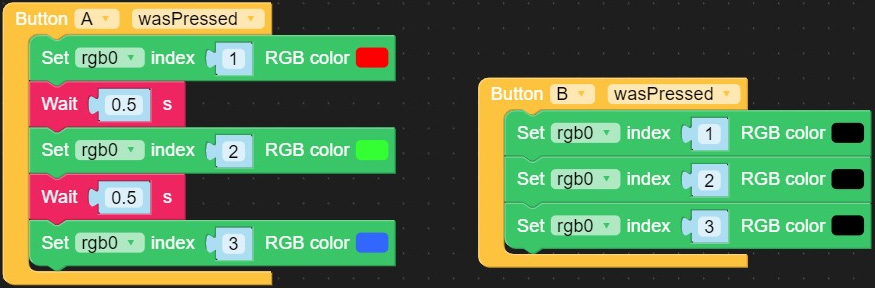
Figure 2.14 – Blockly code for an interactive RGB LED unit
You will run the interactive RGB LED unit Blockly code by pressing the Run button shown in Figure 2.12. When you press the A button on the M5Stack Core, the red, green, and blue LEDs will turn on sequentially. To turn the color LEDs off, you will press the B button. Figure 2.15 illustrates the outcome of the interactive RGB LED unit Blockly code:
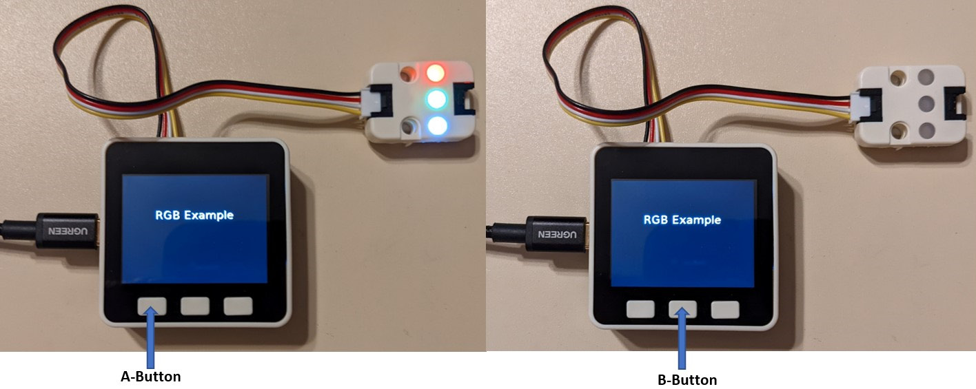
Figure 2.15 – An interactive RGB LED unit Blockly code running on the M5Stack Core
Interactive quiz 2
In reviewing the interactive RGB LED Blockly code shown in Figure 2.14, what is the index value for the green LED?
Congratulations! You have successfully programmed the M5Stack Core to perform some amazing control and UI interactive operations on the RGB LED unit. As demonstrated, laying out text for the M5Stack Core is quite easy and intuitive. In the next section, you will explore the IR remote unit using a handheld IR remote. You can use any available handheld IR remote to investigate the operation of the IR remote unit.
Interacting with an IR remote unit
The IR remote unit is an electronic photoelectric sensor capable of detecting infrared signals. The IR remote unit has an infrared emitter and receiver pair circuit packaged inside the electronic sensor unit. The IR remote unit is shown in Figure 2.16. The IR remote uses an IRM-3638 three-pin integrated circuit (IC). As shown in Figure 2.17, the IRM-3638 IC is responsible for detecting and decoding or demodulating IR signal data.
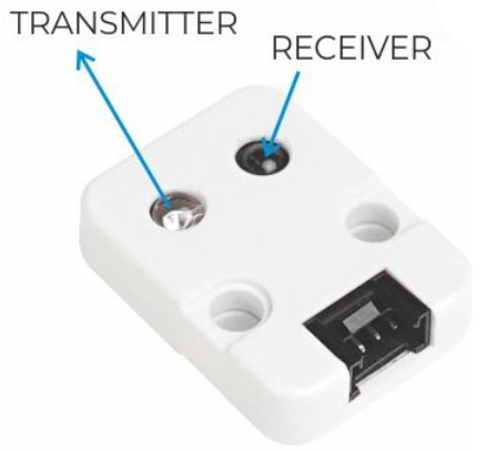
Figure 2.16 – IR remote unit
Figure 2.17 shows a picture of the IRM-3638 IC:

Figure 2.17 – The IR Module (IRM-3638) IC
There is a photodiode used to transmit IR data from the M5Stack Core. The transmit ability of the IR remote unit provides the emitter operation of the photoelectric sensor device. Therefore, you can quite easily build a portable handheld IR remote tester using the M5Stack Core and this photoelectric sensor device. You will be exploring the IR remote unit in the next section with a basic demonstrator.
Programming the M5Stack Core to operate the IR remote unit
You will start the programming process of operating the IR remote unit using the M5Stack Core by electrically connecting the two devices with a four-wire jumper harness. Figure 2.18 shows the attachment of the M5Stack Core to the IR remote unit:
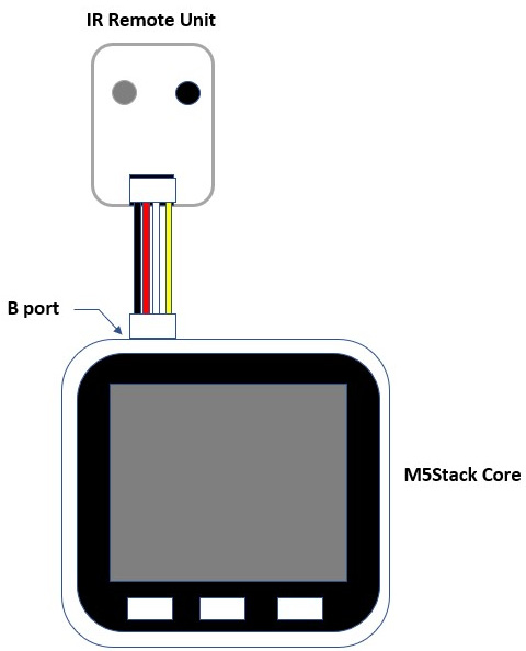
Figure 2.18 – Electrical attachment between the M5Stack Core and the IR remote unit
You will insert one end of the four-wire jumper harness into the M5Stack Core port B. You will take the other end of the four-wire jumper harness and insert it into the IR remote unit. The next step in this hands-on activity is to program the M5Stack Core to detect an IR signal from a handheld IR remote. The three important UIFlow Blockly code blocks enable the IR remote unit to detect infrared signals, and these blocks are shown in Figure 2.19:
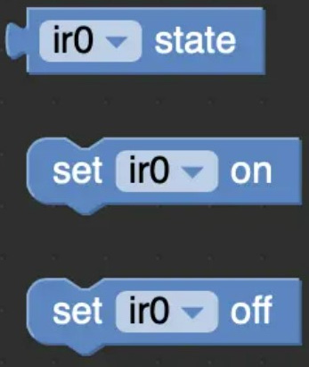
Figure 2.19 – Three important IR remote Blockly code blocks
The ir0 state is the received IR signal. The numerical value returned signifying a detected IR signal is one (1). The set on Blockly code block transmits an IR signal. Finally, the set off Blockly code block stops sending an infrared signal. You will use these three key Blockly code blocks in various M5Stack Core IR remote applications. Next is a basic detection application using the discussed code blocks with the M5Stack IR remote and the M5Stack Core.
Basic IR handheld remote tester
You will build and test a basic IR handheld remote tester using the M5Stack Core and the IR remote unit. To build the tester, you will program and run the Blockly code software shown in Figure 2.20 on the M5Stack Core:
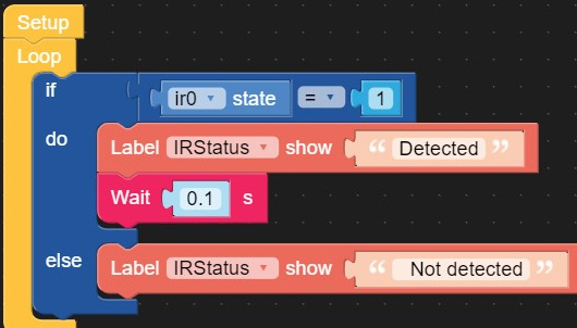
Figure 2.20 – IR signal detection Blockly code
The code will detect the state or presence of an IR signal. Upon detection, the M5Stack Core will display Detected on the thin film technology (TFT) LCD. With no IR signal detected, the TFT LCD will display Not detected. You will set the properties of the M5Stack Core’s UI using the information shown in Figure 2.21. You will run the Blockly code on the M5Stack Core.
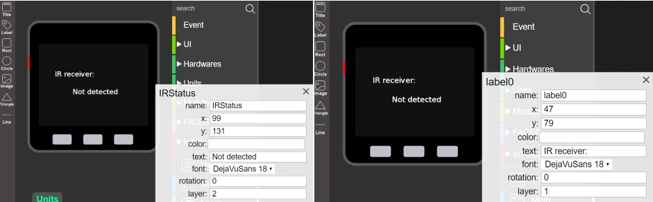
Figure 2.21 – The M5Stack UI properties setup
Note
Add the IR Remote unit to your UI layout design by clicking the plus (+) sign. Select the IR Remote unit icon. Now, you will have access to the IR remote unit’s Blockly code blocks.
Place an IR handheld remote within proximity of the IR remote unit. Press any key on the IR handheld remote and observe the M5Stack Core’s display. Figure 2.22 illustrates the operation of the tester:
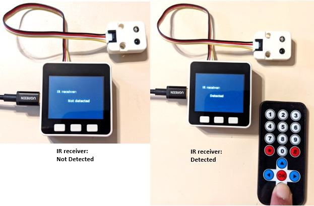
Figure 2.22 – IR remote unit detecting and handheld remote infrared signal
Interactive quiz 3
Using the Blockly code shown in Figure 2.20, change the ir0 state value to zero and observe the operation. Did the detection response work in reverse?
Great job! You have built a programmable tester capable of testing various IR handheld remotes. Experiment with the UI’s display message and program the A and B buttons to create unique testing and detection operations. Include sound to provide a unique tone when an IR signal is detected. In the next section, you will explore the operation of the angle sensor unit.
Interacting with an angle sensor unit
The angle sensor unit uses a basic 10 Kiloohm (KὨ) potentiometer for rotary adjustment of providing control signals. A potentiometer is a three-terminal electrical component that provides a range of resistance values. The primary function is to provide voltage division of an attached voltage supply source to an electrical circuit. Figure 2.23 shows a typical potentiometer:
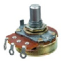
Figure 2.23 – A typical potentiometer
The angle sensor unit is shown in Figure 2.24. This potentiometer-based component attaches to the M5Stack Core’s B-port:
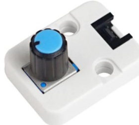
Figure 2.24 – The angle sensor unit
To fully understand the angle sensor unit’s potentiometer and voltage division, you can build an electronic circuit model using the original circuit schematic diagram, as shown in Figure 2.25:
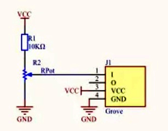
Figure 2.25 – The angle sensor unit circuit schematic diagram
The angle sensor unit circuit analysis
You can use Autodesk Tinkercad Circuits to create a functional breadboard version of the angle sensor unit. Autodesk Tinkercad Circuits is an online circuit simulation environment where various Arduino Uno and BBC micro:bit microcontroller platforms are used to build and test electronic circuit concepts. Figure 2.26 shows a Tinkercad Circuits equivalent of the angle sensor unit circuit schematic diagram shown in Figure 2.25:
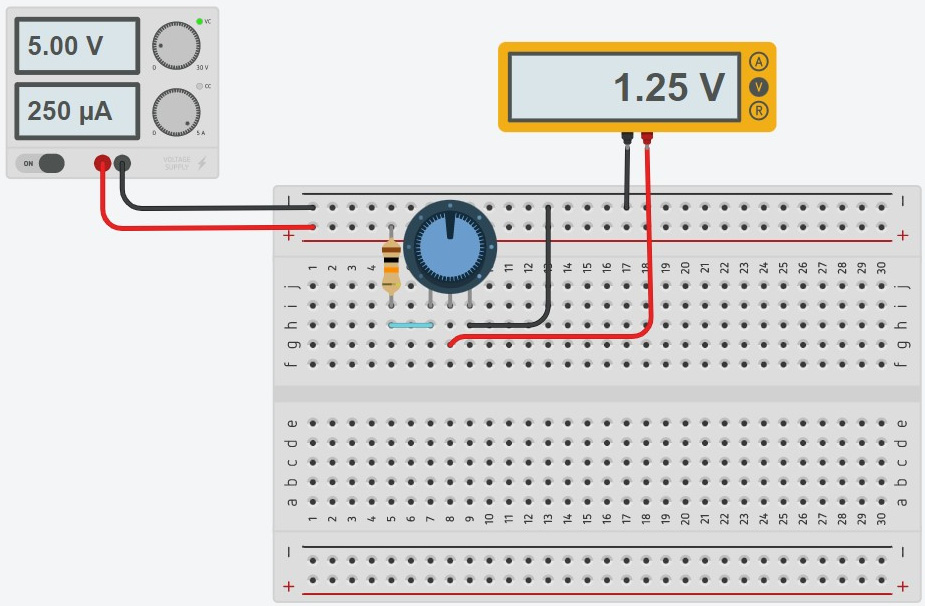
Figure 2.26 – Angle sensor unit Tinkercad circuit
You can use the following website address for tinkering with the Tinkercad circuit shown in Figure 2.26: https://www.tinkercad.com/learn/circuits.
As you can see in Figure 2.26, the potentiometer is set at 50% of the full 10 KὨ resistance value. The voltage measured from the potentiometer is 1.25V. This voltage is determined by multiplying 50% by the direct current (DC) voltage applied to the potentiometer. The voltage applied across the potentiometer is 2.5V. Therefore, 50% x 2.5V is equal to 1.25V. Figure 2.27 shows the voltage drop across the potentiometer of 2.5V. The value of 50% can be written as ½, which is the fractional equivalent to the percentage number. Thus, the circuit is performing a division operation on the potentiometer’s output voltage.
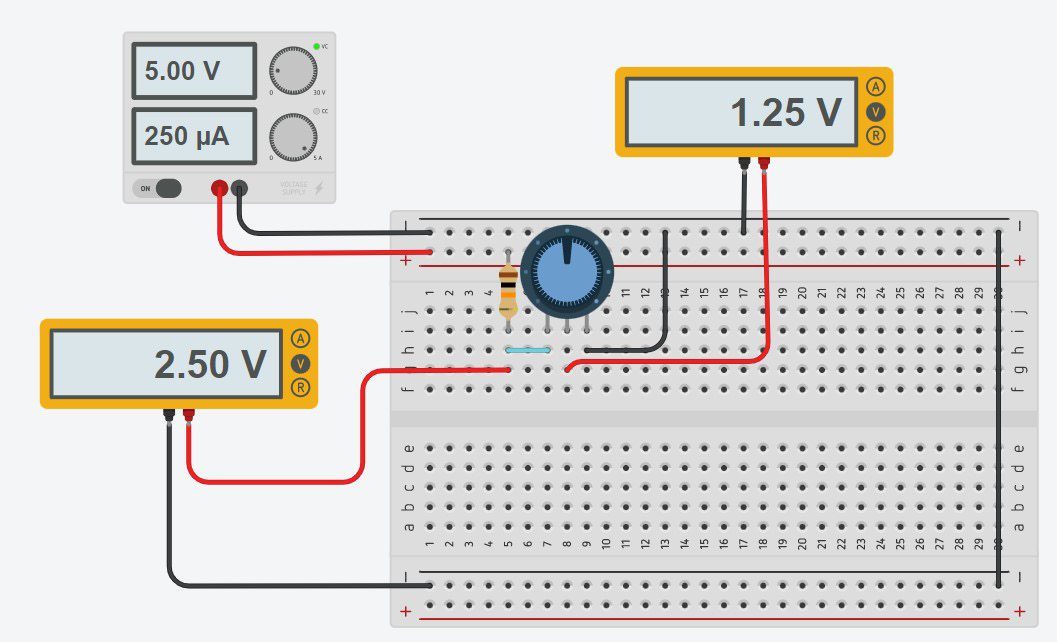
Figure 2.27 – Measuring the potentiometer output voltage drop
Note
Here is a simple equation to use when determining the potentiometer’s output voltage: Vout = percentage x potentiometer voltage drop.
You can see the ease with which the potentiometer’s output can be determined using a circuit simulation model and a basic equation. With such knowledge, you can build your own angle sensor unit using a 10 KὨ potentiometer and a fixed 10 KὨ resistor. Figure 2.28 illustrates a Homebrew angle sensor unit you can build using the specified passive components.
Interactive quiz 4
What is the Vout with an adjusted potentiometer voltage percentage of 30%?
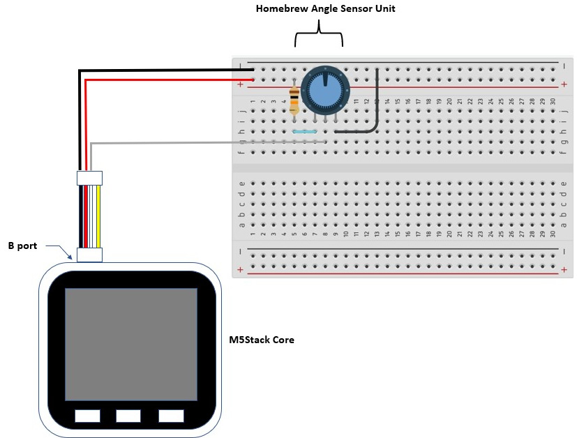
Figure 2.28 – A homebrew angle sensor unit
To obtain a greater understanding of this circuit analysis discussion, you will test the original angle sensor unit and the homebrew device in the next section. You will program the M5Stack Core to read the angle sensor and display an analog-to-digital converter value on the TFT LCD.
Programming the M5Stack Core to read the angle sensor unit
You will start the programming process of reading the angle sensor unit using the M5Stack Core by electrically connecting the two devices together with a four-wire jumper harness. Figure 2.29 shows the attachment of the M5Stack Core to the angle sensor unit:
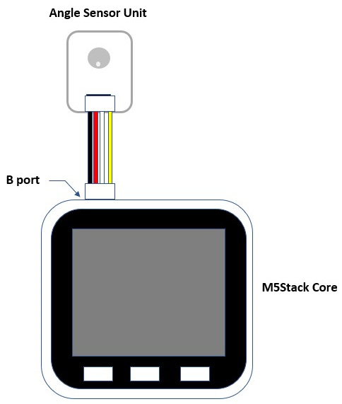
Figure 2.29 – Electrical attachment between the M5Stack Core and the angle sensor unit
You will insert one end of the four-wire jumper harness into the M5Stack Core B-port. You will take the other end of the four-wire jumper harness and insert it into the angle sensor unit. The next step in this hands-on activity is to program the M5Stack Core to detect and display angle rotation from the sensor. You can set up UIFlow to interact with the angle sensor unit by adding the potentiometer device to the programming environment. Figure 2.30 shows the angle sensor included in the UI layout section of the UIFlow programming environment:
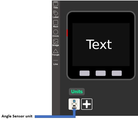
Figure 2.30 – Adding the angle sensor unit to the UIFlow UI layout section
By adding the unit to the UI layout section, you have access to the angle sensor unit Blockly coding block, as shown in the following figure:

Figure 2.31 – Angle sensor unit Blockly coding block
You can easily create an M5Stack Core display device that will display the equivalent angle value. The displayed angle numeric represents the unit’s equivalent analog-to-digital converter (ADC) value. The maximum ADC value that can be displayed is 1,024. You will use the following Blockly code to read the angle sensor unit’s equivalent ADC value and display it on the M5Stack Core’s TFT LCD. The angle sensor unit’s Blockly code is shown in Figure 2.32:
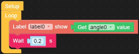
Figure 2.32 – Angle sensor unit ADC display Blockly code
You will set the properties of the M5Stack Core’s UI using the information shown in Figure 2.33. You will run the Blockly code on the M5Stack Core:
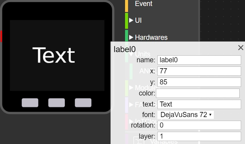
Figure 2.33 – The M5Stack UI properties setup
You will see the minimum ADC value of 0.0 to the maximum value of 1024.0 displayed on the TFT LCD shown next. These values are displayed by adjusting the angle sensor unit’s potentiometer. Figure 2.34 illustrates the adjustment of the angle sensor and its equivalent ADC values:
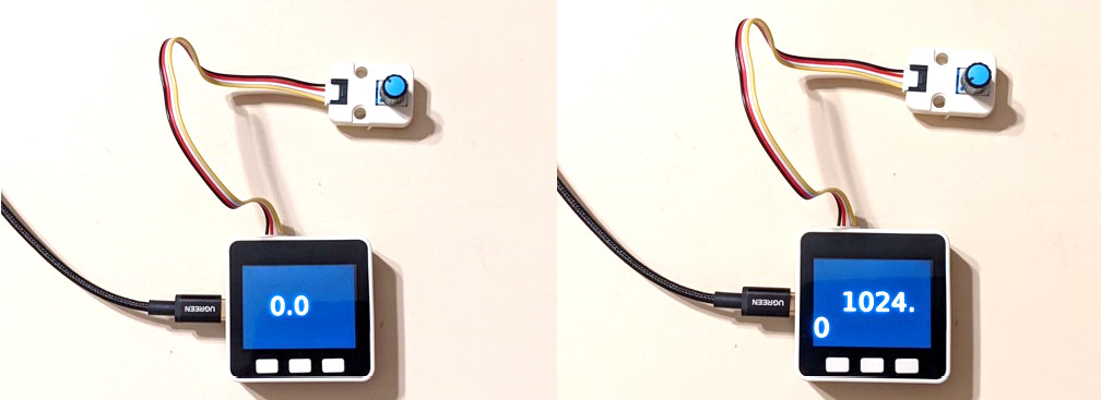
Figure 2.34 – ADC minimum and maximum values displayed on the TFT LCD
Note
The ADC value of 0.0 is equated to 0V and the ADC value of 1024.0 aligns with 5V.
Congratulations, you have created a UI appliance that displays ADC values using the angle sensor unit and the M5Stack Core. As a final lab project, you can create a small interactive numeric display using the main ADC value obtained from the angle sensor unit. You can use additional Blockly code blocks to create this small interactive numeric display. Figure 2.35 provides the revised code for the small numeric interactive display:
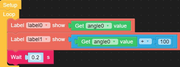
Figure 2.35 – Blockly code blocks for a small numeric interactive display
You will need to add a label (label1) to display the small numeric values produced by the angle sensor unit and Blockly code previously shown in Figure 2.35. You will configure label1 using the properties shown in Figure 2.36 to display the new numeric values:
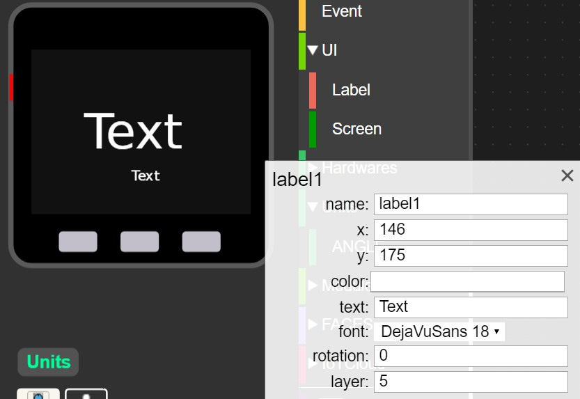
Figure 2.36 – label1 properties
With the code built and the label properties settings configured, you can run the code on M5Stack Core. You will see a small numeric display underneath the original text. The small numeric display is one-hundredth smaller than the original value. Figure 2.37 shows the new M5Stack Core display:
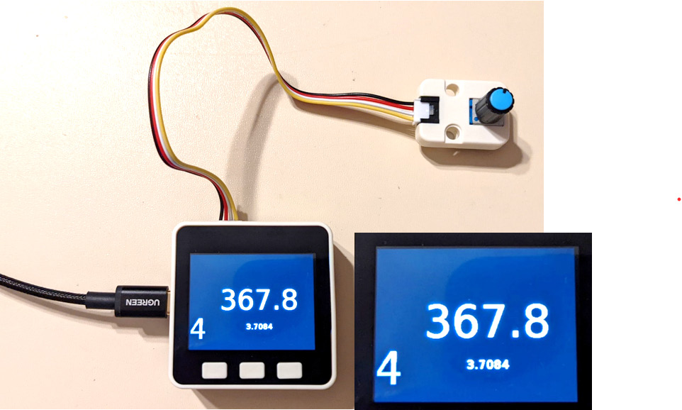
Figure 2.37 – M5Stack Core displaying an interactive small numeric display
Interactive quiz 5
Adjust the angle sensor unit’s potentiometer to approximately 611 and observe the small numeric value displayed on the M5Stack Core’s TFT LCD. Is the small numeric value displayed approximately one-hundredth of the original number?
Again, congratulations on creating this enhanced angle sensor unit demonstrator. In the final section of this chapter, you will investigate the inner workings of the motion unit. You will learn the basic operation of a passive infrared (PIR) sensing device through a hands-on activity. The hands-on activity will consist of attaching the motion unit with a four-wire jumper harness to the M5Stack Core and coding a basic human detection application. The cognitive knowledge and hands-on skills obtained in the previous sections will allow you to code and test a motion unit enabled by the M5Stack Core.
Interacting with a motion sensor unit
The motion sensor unit detects an object or a human’s emitted heat energy using a passive pyroelectric IR detector. The device is passive based on no external power supply being needed to operate the detector. The pyroelectric crystal serves as the heat or IR detection element within the motion unit. When the pyroelectric crystal detects heat or IR, the surface of the crystal produces an electric charge. This electric charge is sent to an electronic switch that controls a visual signaling device, such as an LED. Figure 2.38 shows the M5Stack motion sensor unit:
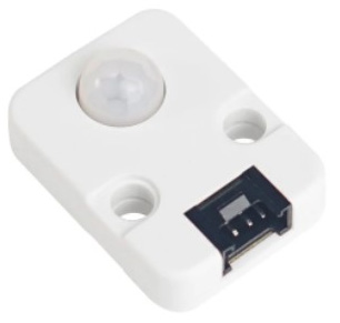
Figure 2.38 – An M5Stack motion sensor unit
Note
The change in a material’s surface charge in response to temperature variations is known as the pyroelectric effect.
When the motion sensor unit detects an IR source, the device’s output pin turns on. The output signal stays on for approximately 2 seconds. When the IR source is removed from the motion sensor unit, its output turns off. The motion sensor unit continuously monitors IR sources such as the human body or an object’s heat energy. The main sensing element that is inside the motion sensor unit is a PIR AS312 component. The PIR AS312 component has a pyroelectric sensor that detects the human body or object’s emitted IR energy. Figure 2.39 illustrates an example PIR AS312 component:
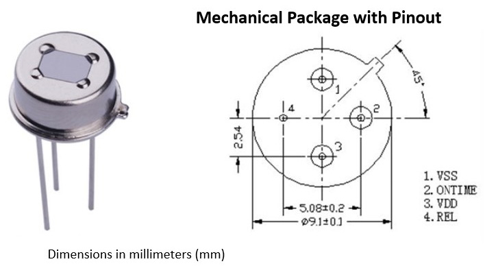
Figure 2.39 – A typical pyroelectric PIR AS312 component
The schematic diagram of the motion sensor unit is shown in the following figure:
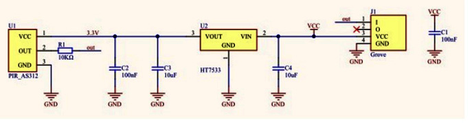
Figure 2.40 – The motion sensor unit’s electronic circuit schematic diagram
The M5Stack Core assigned general-purpose input-output (GPIO) pinout is GPIO36. The pinout table shown next illustrates port B and the assigned GPIO36 pin:

Figure 2.41 – The M5Stack Core assigned GPIO pin for the motion unit
In the next section, you will attach the motion sensor unit to the M5Stack Core using a four-wire jumper harness. You will then test the basic detection device with a simple PIR Blockly code application. This activity will check the electrical connection between the motion unit and the M5Stack Core using the PIR application.
Programming the M5Stack Core to detect a human body with the motion sensor unit
You will start the programming process of detecting the human body with the motion sensor unit and the M5Stack Core by electrically connecting the two devices together with a four-wire jumper harness. Figure 2.42 shows the attachment of the M5Stack Core to the motion sensor unit. As shown in Figure 2.42, port B is used for the Motion Sensor unit to communicate with the M5Stack Core:
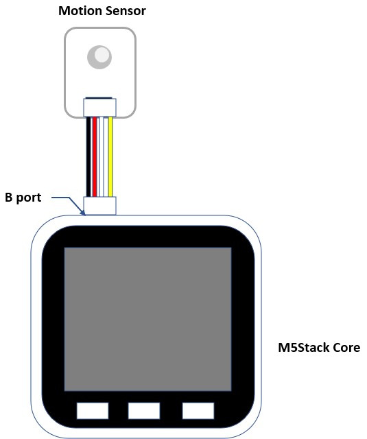
Figure 2.42 – Electrical attachment between the M5Stack Core and the Motion Sensor unit
You will insert one end of the four-wire jumper harness into the M5Stack Core B-port. You will take the other end of the four-wire jumper harness and insert it into the Motion Sensor unit. The next step in this hands-on activity is to program the M5Stack Core to detect and display that a human body is present. You can set up UIFlow to interact with the motion sensor unit by adding the pyroelectric device to the programming environment. Figure 2.43 shows the motion sensor unit included in the UI layout section of the UIFlow programming environment:
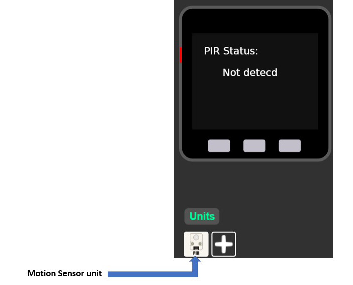
Figure 2.43 – Adding the motion sensor unit to the UIFlow UI layout section
By adding the unit to the UI layout section, you have access to the PIR unit Blockly coding block, as shown in Figure 2.44:
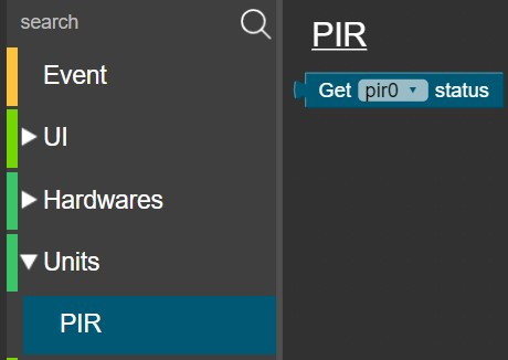
Figure 2.44 – PIR unit Blockly coding block
You can easily create an M5Stack Core display device that will display when a human body has been detected. The TFT LCD will initially display PIRStatus: Not detected. Upon detecting a human body, the TFT LCD will display PIRStatus: Detected. You will use the following Blockly code to read a human body’s IR energy with the Motion Sensor unit. The Motion Sensor unit will display the detection message Detected when a human body is sensed. The Motion Sensor unit’s Blockly code is shown in Figure 2.45:
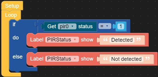
Figure 2.45 – Blockly code blocks for the motion sensor unit human body detector
You will set the properties of the M5Stack Core’s UI using the information shown in Figure 2.46 for label1:
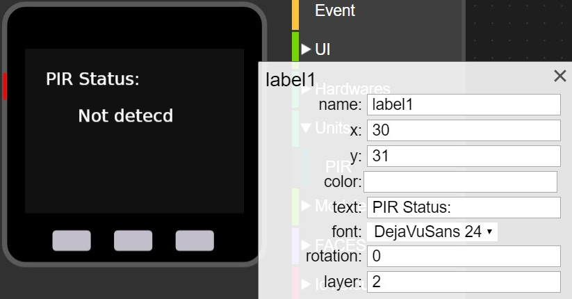
Figure 2.46 – label1 properties
You will set the properties of the M5Stack Core’s UI using the information shown in Figure 2.47 for the PIRStatus label:
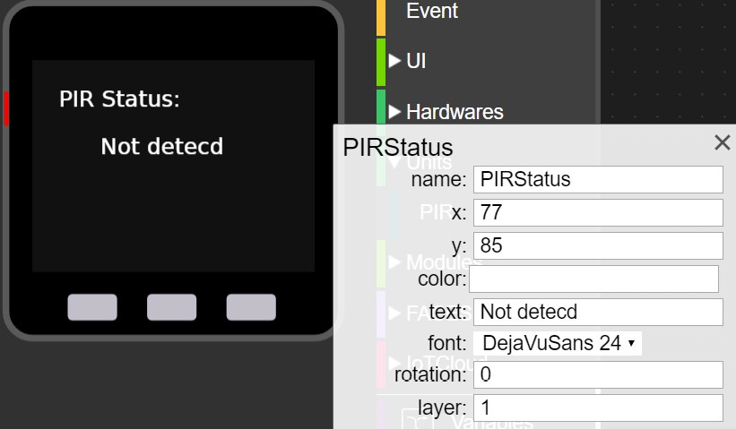
Figure 2.47 – PIRStatus label properties
You will run the Blockly code on the M5Stack Core. You will see that the PIR status initially displayed Not detected on the TFT LCD. As you approach the Motion Sensor unit, after approximately 2 seconds, the TFT LCD will display Detected. These status messages will continuously toggle based on the presence or absence of a human body within the Motion Sensor unit. Figure 2.48 illustrates the toggling of the PIR status messages on the TFT LCD:
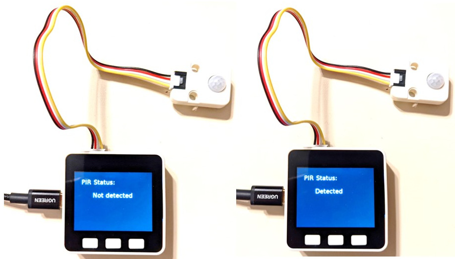
Figure 2.48 – Motion Sensor unit human body PIR Status detection
Interactive quiz 6
The sample code used a binary value of 1 assigned to the Get pir0 status code block. Change the binary value to 0 and observe the detection unit’s response. Did the change produce the opposite response?
You have completed the motion sensor activities successfully and now understand the operation of a pyroelectric detection device. The interactive quiz presented will have allowed you to explore an inverted operation response of the motion sensor in detecting human bodies. In addition, the interactive quiz will have allowed you to check your knowledge using a hands-on assessment approach to learning about the basic operation of the motion sensor.
Summary
Congratulations, you have completed the hands-on activities and interactive quizzes in this chapter, in which you learned about the technology used in the M5Stack Core unit. You learned how to electrically connect the RGB LED, IR Remote, and angle and motion sensor units to the M5Stack Core using a four-wire jumper harness. Further, you learned about the key electrical or electronic sensing and visual component used with each unit. For the angle sensor unit, you learned how to wire a virtual device using the online Tinkercad Circuits website. You learned how the angle sensor unit’s potentiometer produces a proportional output voltage based on the percentage of the supply voltage applied to the variable resistor. With this knowledge, you learned how to measure the potentiometer’s percentage of output voltage using a Tinkercad Circuits multimeter.
Additionally, you learned how to add and set up each unit’s UI properties within the UIFlow software. You learned how to test each M5Stack unit’s basic operation using simple code blocks. With these UIFlow code block applications, you were able to gain an understanding of how to read and display each unit’s electrical output properties on M5Stack Core’s TFT LCD. You were able to test your coding knowledge by answering the interactive quizzes through hands-on investigation.
With this knowledge, you will be able to explore the M5Stack Core hardware in the next chapter. The M5Stack Core hardware is an electronic subcircuit that works with the ESP32 hardware architecture and the UIFlow Blockly code discussed in Chapter 1. You learned about the internal electronic subcircuits that aid in the ESP32 hardware architecture of the M5Stack Core.
You will use this electronic circuits knowledge, design layout approaches, and the UIFlow IDE to program the internal hardware in Blockly code to create engaging and interactive devices in the next chapter.
Interactive quiz answers
- Interactive quiz 1: The LED turned on faster
- Interactive quiz 2: The index value for the green LED is 2
- Interactive quiz 3: Yes, the detected message initially displays first
- Interactive quiz 4: The potentiometer output voltage (Vout) equals 0.75 or 750mV
- Interactive quiz 5: Yes, the message initially displays first
- Interactive quiz 6: Yes, the response will be inverted because of the change of the binary bit value