
4
It’s a SNAP! Snap Circuits and the M5Stack Core
In the previous chapter, you learned about the various hardware circuits that extend the operational functions of the M5Stack Core. You learned about the various hardware circuits that allow motion, light, and sound to appeal to the user of an M5Stack Core. You learned how to access the UiFlow Blockly code palette to program the M5Stack Core to utilize a vibration motor, a speaker, and the RGB LED. Furthermore, you learned how to wire a littleBits vibration motor to the M5Stack Core and program it to operate as a haptic device. With the knowledge of creating a block diagram and electronic circuit schematic diagram obtained in Chapter 3, you will be able to wire the M5Stack Core to operate various Snap Circuits devices. In this chapter, you will explore the M5Stack Core as a mini, programmable controller that operates various electronic circuits. You will be introduced to Snap Circuits, followed by an explanation of a version of an electronic learning product called the Arcade Games kit; you will learn how to enhance the Arcade Games user experience with Snap Circuits using an M5Stack Core; and you will learn how to wire the M5Stack Core using a basic electrical interfacing control circuit.
By the end of this chapter, you will have learned how to perform the following technical tasks with the M5Stack and Snap circuits:
- Drawing a typical M5Stack Core mini controller circuit schematic diagram
- Wiring and programming a Snap Circuits LED Display and Microcontroller (LED MC) module dice game
- Wiring, programming, and controlling an M5Stack Core Snap Circuits MC LED numbers and letters device
- Wiring, programming, and controlling an M5Stack Core Snap Circuits alarm device
- Wiring, programming, and controlling an M5Stack Core Snap Circuits counter with a sound device
In this chapter, we are going to cover the following main topics:
- What are Snap Circuits?
- What is a Snap LED MC module?
- Building an M5Stack Core Snap Circuits numbers and letters device
- Building an M5Stack Core Snap Circuits alarm device
- Building an M5Stack Core Snap Circuits counter with a sound device
Technical requirements
To engage with the chapter’s learning content, you will need the M5GO IoT Starter Kit to explore the internal and external hardware, electronics, and software coding of your first basic application. You will need the Snap Circuits Arcade Game learning product, an electromechanical relay, and jumper wires. The UiFlow code block software will be required to build and run the M5Stack Core mini programmable controller applications.
You will require the following:
- The Snap Circuits Arcade Game learning product
- The M5Stack Core
- The M5GO IoT Starter Kit
- UiFlow code block software
- Snap Circuits jumper wires
- A USB C cable
- 3 AA batteries
- A Snap Circuits AC adapter
- An electromechanical relay module
The GitHub repository for the software resources is at https://github.com/PacktPublishing/M5Stack-Electronic-Blueprints/tree/main/Chapter04.
What are Snap Circuits?
Snap Circuits are electrical and electronic components mounted on colorful plastic shapes. Each colorful shape has a metal snap at key connecting points of the electrical and electronic component. The electrical and electronic component provides the specific function for the Snap Circuits part.
Therefore, a Snap Circuits part can be described as a functional block based on an electrical and electronic component mounted onto a plastic base. Figure 4.1 shows some example Snap Circuits blocks:

Figure 4.1 – Snap Circuits blocks
The Snap Circuits block designated by the number 2 is a wire block. You connect Snap Circuits blocks using this component. There are various types of wire blocks based on length. For example, there are wire blocks with lengths of 3, 4, and 5. The 1-wire snap is packaged into a plastic circle. You will use this snap component to provide an electrical stand-off to structurally align the other Snap Circuits and wire blocks properly. Figure 4.2 shows a 1-snap wire:

Figure 4.2 – Snap Circuits blocks
Besides using wire blocks to attach Snap Circuits components together, you can use jumper wires. Like the wire blocks, jumper wires provide a flexible approach to connecting Snap Circuits blocks remotely. For example, a pushbutton switch Snap Circuits block can be wired several inches from the main electrical sound, control, or amplifying circuit. You can create alarm circuits that require trip wires to be strategically placed in a designated detection zone. Some examples of Snap Circuits jumper wires are shown here:

Figure 4.3 – Snap Circuits jumper wires
To provide a stable platform to mount and attach the Snap Circuits blocks, you will use a base grid. You may think of the base grid as a printed circuit for wiring Snap Circuits. The Snap Circuits, wire blocks, and jumper wires are placed onto the base grid plastic stubs. The placement of these components provides mechanical rigidity and proper electrical conductivity for the Snap Circuits device. Figure 4.4 shows a Snap Circuits base grid:

Figure 4.4 – Snap Circuits base grid
Now that you understand Snap Circuits, in the next section, you will learn about the LED Display and Microcontroller (LED MC) module.
What is a Snap LED MC module?
The Snap LED MC module is a dual seven-segment LED display driven by a microcontroller and supporting electronic parts. The microcontroller is a PICAXE-08M2 integrated circuit. The PICAXE-08M2 microcontroller is an eight-pin integrated circuit. The chip has flash memory, thus allowing it to be programmed easily. Figure 4.5 shows a photo of a PICAXE-08M2 microcontroller:

Figure 4.5 – The PICAXE microcontroller
The LED MC is pre-programmed with 21 arcade-based games. Some of the game titles are binary coded decimal, changing speed, the baseball game, and home run derby. The arcade games are accessible using a selector switch and a sequence of instructions. Several snaps provide various electrical control functions that allow the LED MC to provide the arcade games previously listed. Figure 4.6 shows the LED MC with its snap functions:

Figure 4.6 – The LED MC
The circuit schematic diagram for the LED MC is shown in Figure 4.7:

Figure 4.7 – The LED MC electronic circuit schematic diagram
With your knowledge about the LED MC, you will build a Snap Circuits arcade game numbers and letters device operated by an M5Stack Core. You will learn how to wire the numbers and letters device using Snap Circuits blocks and an M5Stack Core. You will learn how to wire an electromechanical relay to an M5Stack Core to operate the Snap Circuits device.
Building an M5Stack Core Snap Circuits numbers and letters device
The Snap Circuits Arcade Game numbers and letters device will allow a sequence series of letters and numbers to be displayed on the LED MC. Typically, the selector switch’s C button is used to manually sequence the letters and numbers. You will bypass the selector switch with an M5Stack controller. The M5Stack controller will be wired to an electromechanical relay. The electromechanical relay’s contact will act as the replacement for the C button. A basic block diagram of the controller design is shown in Figure 4.8:

Figure 4.8 – M5Stack controller block diagram
You will use an off-the-shelf electromechanical relay module to act as the switching interface device between the M5Stack Core and the LED MC. This kind of electromechanical relay module device is shown in Figure 4.9. The electromechanical relay module has one set of normally opened switching contracts – therefore, the component is known as a single-pole, single-throw device. In datasheets and electrical engineering textbooks, the single-pole, single-throw electromechanical relay normally-opened contacts are abbreviated to SPST NO.
Quiz 1
If SPST NO is the abbreviation for single-pole, single-throw normally open, what is SPST NC?

Figure 4.9 – An electromechanical relay module with SPST NO contacts
The electronic circuit schematic diagram symbol for an electromechanical relay with SPST NO contacts is shown in Figure 4.10.

Figure 4.10 – A typical schematic diagram of an electromechanical relay with an SPST NO contacts symbol
The electromechanical relay module uses a transistor to drive or operate the coil of the electromechanical relay. The transistor will provide a ground for the electromechanical relay upon being biased properly by the resistor combination of R1 and R3. The combination of R1 and R3 forms a voltage divider circuit capable of operating the transistor properly. The biasing or the DC operating point will provide sufficient current flow from the transistor’s collector-emitter circuit. With sufficient current flowing through the collector-emitter circuit, the transistor will provide a ground or low-side voltage rail for one side of the electromechanical relay’s coil. The other side of the electromechanical relay’s coil is wired to the high side or 3 V DC rail established by the 3 V voltage regulator.
The M5Stack Core control voltage provides the proper biasing for the transistor-relay driver circuit to operate the electromechanical relay. The M5Stack Core’s control voltage is applied at point D1 of the R1 resistor. The VCC or collector supply voltage is a 5 V DC source provided by the M5Stack Core. The electronic circuit schematic diagram for the electromechanical relay module is shown in Figure 4.11:

Figure 4.11 – An electronic circuit schematic diagram of the electromechanical relay module
You will connect the electromechanical relay module and the M5Stack Core using individual jumper wires. The individual wires are inserted into the three respective cavities of the jumper harness connector. The colors of the three respective cavities are red, black, and white. The electrical wiring diagram you will use to connect the M5Stack Core to the electromechanical relay module to build the M5Stack controller is shown in Figure 4.12:

Figure 4.12 – M5Stack controller electrical wiring diagram
In addition to the electrical wiring diagram shown in Figure 4.12, you may use Figure 4.13 to assist in attaching the M5Stack Core to the electromechanical relay module. You will notice in the figure that the electrical wiring scheme is equivalent to what is depicted in Figure 4.12. You will use this mini programmable controller to operate the Snap Circuits Arcade Games numbers and letters device.

Figure 4.13 – Pictorial of an M5Stack controller
Quiz 2
In reviewing the electrical wiring diagram shown in Figure 4.12, what function does the white jumper wire provide the M5Stack controller with?
With the electromechanical relay attached to the M5Stack Core, you are ready to build the Snap Circuit numbers and letters device. You will use the pictorial diagram in Figure 4.14 to guide your building of the Snap Circuit numbers and letters device:

Figure 4.14 – Pictorial drawing of the Snap Circuits numbers and letters device
You will use snap number one (1) shown in Figure 4.14 to properly align the snap wires appropriately to the matching electronic components. You will attach the electromechanical relay module’s SPST NO contacts to the selector switch using Snap Circuits jumper wires. You will notice an AC adapter (B6) is used instead of a battery pack. The AC adapter is used to avoid purchasing batteries. You may use a battery pack or the AC adapter’s 5 V source to power your Snap Circuits device. The jumper wires will be attached to points E and F on the base grid. Figure 4.15 shows the Snap Circuits jumper wires attached to the electromechanical relay SPST NO contact:

Figure 4.15 – Attaching Snap Circuits jumper wires to the electromechanical relay module
Quiz 3
Looking at Figure 4.14, the slide switch (S1) is attached to what snap of the LED MC?
A bigger-picture perspective of the M5Stack Core interfaced with the Snap Circuits numbers and letters can be viewed in the electronic circuit schematic diagram. You will notice that the electromechanical relay module’s SPST NO contact is wired in parallel with the C switch of the selector switch. The C switch is bypassed using the electromechanical relay module’s contact, operated by the M5Stack Core. Figure 4.16 shows the electronic circuit schematic diagram:

Figure 4.16 – Electronic circuit schematic diagram for the M5Stack controller Snap Circuits numbers and letters device
You can use the following pictorial to assemble the final M5Stack controller Snap Circuits numbers and letters device:

Figure 4.17 – M5Stack controller Snap Circuits number and letters device
To secure the electromechanical relay module, you can use two small globs of mounting putty. Place the mounting putty on each side and on top of the Printed Circuit Board (PCB) to the base grid. You can attach the M5Stack Core to the base grid using a small LEGO plate and brick. The LEGO plate and brick combination will attach to the back of the M5Stack Core. Placing mounting putty on the bottom of the LEGO brick will secure the M5Stack Core to the base grid. Figure 4.18 illustrates this mechanical attachment scheme:

Figure 4.18 – Adding a mechanical attachment feature to the M5Stack Core
Congratulations, you have assembled the M5Stack controller Snap Circuits numbers and letters device! Pressing the C switch manually will sequence and display the numbers and letters on the LED MC module. In the next step of this project, you will add the control software to the M5Stack Core. The software will allow the Snap Circuits number and letters device to operate automatically. The M5Stack Core’s software will allow the LED MC’s program to sequence through a series of numbers and letters automatically. In total, there are 29 letters and numbers pre-programmed into the LED MC.
Game selection procedure
Before proceeding in developing the UiFlow Blockly code for the M5Stack Core, here is the LED MC game selection procedure you may use for obtaining the Snap Circuits numbers and letters arcade game. You will first turn on the LED MC by sliding the S1 switch to the on position. The LED MC will display 00. You will press the A button on the selector switch. You will continue to press the switch until 11 is displayed. You will press the B button on the selector switch. The LED MC will display Go (the word) and the speaker will beep. Lastly, you will press the selector switch’s C button to sequence the LED MC to display the 29 numbers and letters.
Interactive quiz 1
By changing the repeat value to 5, what number will be displayed on the LED MC?
The M5Stack Core controller’s software
You will program the M5Stack Core’s controller using UiFlow Blockly code. UiFlow Blockly code will provide control over the electrical wired electromechanical relay’s SPST contact. You will be able to start the sequencing of the numbers and letters using the UiFlow Blockly code UI. With the UI, the sequence of the numbers and letters will be initiated by the electromechanical relay’s SPST contact. Figure 4.19 shows the M5Stack controller UiFlow Blockly code:

Figure 4.19 – The M5Stack controller UiFlow Blockly code
You will use the UI layout to define the text and the appearance of the M5Stack controller, as shown in Figure 4.20:

Figure 4.20 – The M5Stack controller UI
To execute the device, use the steps discussed in the game selection procedure. Remember, you will not be using the C button on the selector switch. Instead, the M5Stack controller will automatically be sequenced through the pre-programmed code of the LED MC. You will execute the UiFlow Blockly code to the M5Stack Core using the UiFlow run button. You now have a development template to construct and operate the remainder of the projects in this chapter.
Building an M5Stack Core Snap Circuits alarm device
In this section, you will wire a Snap Circuits alarm device that is controlled by the M5Stack controller. The alarm circuit device will be operated by the electromechanical relay module used in the previous project. The electromechanical relay module’s switching action will be influenced by the M5Stack Core’s UiFlow Blockly code. The UiFlow Blockly code will alternately switch the Snap Circuits alarm device on and off. The switching contact of the electromechanical relay module will provide a symmetric-based alarm sound, thus getting the attention of a bystander. The main Snap Circuits module that will provide the audible sound is the ALARM IC. Figure 4.21 shows the Snap Circuits alarm IC and electrical connections.
Note
The Snap Circuits alarm IC module uses a custom Application-Specific Integrated Circuit (ASIC) to produce several audible sounds.

Figure 4.21 – The Snap Circuits ALARM IC module
The ALARM IC module uses an ASIC that allows various sounds to be produced. The sounds that can be produced with the electronic module are a siren, machine gun, fire engine, and European siren. To aid in the sound generation produced by the electronic module, there is a resistor and NPN transistor parts wired to the custom IC. The resistor provides sufficient gain for the ALARM IC module with the NPN transistor driving a speaker. The circuit schematic diagram of the custom IC design is shown in Figure 4.22.
Quiz 4
In reviewing Figure 4.21, a pushbutton switch would be attached to which connection snap of the ALARM IC module?

Figure 4.22 – The custom IC circuit schematic diagram
You can start to assemble the M5Stack controller Snap Circuits ALARM IC device using the pictorial diagram shown in Figure 4.23. Figure 4.23 illustrates the placement locations of the ALARM IC module, M5Stack Core, and the electromechanical mechanical relay module on the base grid. With the placement of the components on the base grid, the device can easily be tested using the slide switch (S1).

Figure 4.23 – Placement of the Alarm IC device components on the Snap Circuits base grid
Place the slide switch (S1) in the on position. With the slide switch in the on position, an alarm sound shall be heard through the speaker. Congratulations, you have built a Snap Circuits alarm device!
Note
You can design your own assembly layout diagrams using the Snap Circuits Designer. To obtain the design tool, go to the following website: https://www.elenco.com/snap-circuits-designer/.
As a reference, the electronic circuit schematic diagram for the Snap Circuits ALARM IC circuit is shown next:
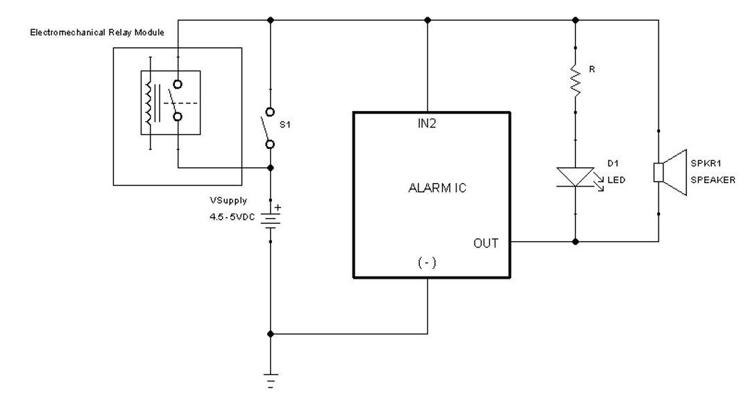
Figure 4.24 – Snap ALARM IC circuit schematic diagram
You will notice a series limiting resistor (R) and LED (D1) in the electronic circuit schematic shown in Figure 4.24. The D2 block is constructed using these two discrete electronic components. Therefore, you can wire your own LED circuit following the circuit configuration shown in Figure 4.24. A 330-ohm resistor value will provide the appropriate current limiting needed to prevent the LED from being damaged. As a final assembly reference, here is the completed project build of the M5Stack controller – the Snap Circuits ALARM circuit device is shown in Figure 4.25. You are now ready to program the M5Stack Core to operate the Snap Circuits ALARM device using the UiFlow Blockly code software.

Figure 4.25 – The completed built M5Stack controller – Snap ALARM device
You can use the UI layout as shown in Figure 4.26 to create the operator controls to operate the Snap Circuits ALARM device:

Figure 4.26 – The Snap ALARM device UI controls layout
You can use the following UiFlow Blockly code to operate the Snap Circuits ALARM device using the M5Stack Core:

Figure 4.27 – M5Stack Core Blockly code
You will start the Snap Circuits alarm circuit operation by executing the code shown in Figure 4.27 to the M5Stack Core using the UiFlow run button. To ensure the proper operation of the alarm under the control of the M5Stack Core, you will place the slide switch (S1) in the off position. Pressing the A button on the M5Stack Core will cause the alarm to sound repeatedly five times. The B button will cause the alarm to sound once for 1 second. Figure 4.28 shows the M5Stack Core’s UI in operation.
You can create a fire engine sound with your M5Stack controller Snap Circuits Alarm device by adding a snap wire between the IN1 and ground (-) snaps. Figure 4.29 illustrates this electrical connection. With this suggested modification, document the change in a journal or spiral notebook.
Note
As suggested in the previous paragraph, take a journal or spiral notebook and transform it into an engineer’s notebook to document new M5Stack Core design ideas!

Figure 4.28 – A functional M5Stack Core UI
Creating a fire engine sound using this Snap Circuits modification design is shown in Figure 4.29:

Figure 4.29 – Fire engine sound
Interactive quiz 2
Modify the Snap Circuits ALARM as shown in Figure 4.30. Run the Snap Circuits ALARM device code on the M5Stack Core: what sound is produced by the modification?

Figure 4.30 – Interactive quiz 2 circuit
Congratulations – you have successfully built an interactive alarm using Snap Circuits components and the M5Stack Core. As illustrated in this project, the M5Stack Core provides a control method for operating the alarm using a manual or automation UI approach. The M5Stack Core allows the alarm to be repetitive or single-operated by pressing the operate button on the ESP32-based programmable controller. In the final project, you will learn how to add sound with a decimal counter. You will use the LED MC, the alarm IC, and a speaker to create this unique analog and digital device.
Building an M5Stack Core Snap Circuits counter with a sound device
In this final project, you will use the knowledge obtained on building Snap Circuits to construct a counting sound device. You will learn how to repurpose the alarm device to work with the LED MC. The project’s concept of reuse consists of controlling the counting feature of the LED MC and adding an audible sound. The audible sound resembles a machine gun when the ALARM IC module is triggered. The LED MC will rapidly display numbers based on the module’s S-IN input being triggered for a specified time duration. You will make a slight modification to the M5Stack Core’s UI to reflect the name of the project. The concept block diagram for the M5Stack controller counting sound device is shown in Figure 4.31:

Figure 4.31 – M5Stack controller Snap Circuits counting sound device block diagram
Reviewing the block diagram shown in Figure 4.31, you will notice the transistor relay driver circuit triggering the LED MC and alarm IC. The length of the time for which the trigger signal is engaged is directed by the M5Stack Core’s Blockly code. A long trigger signal time allows a rapid count to be displayed on the LED MC. In parallel with the transistor relay driver circuit, there is a manual momentary pushbutton switch capable of providing a similar trigger signal function. In contrast, the manual pushbutton switch can be considered a testing feature for the counting sound device. A long press of the momentary pushbutton switch will allow for rapid counting and a long duration of the machine gun sound.
To provide a circuit perspective view, an electronic circuit schematic diagram is shown in Figure 4.32. You will notice the electromechanical relay module wired in parallel with the momentary pushbutton switch. As discussed in the previous paragraph, you can test the counting sound device manually using the momentary pushbutton switch. The M5Stack Core Blockly code provides both automated and manual modes of operation for the counting sound device.
Note
Connecting the IN2 and IN3 snap pins will allow the alarm IC module to produce a machine gun sound.
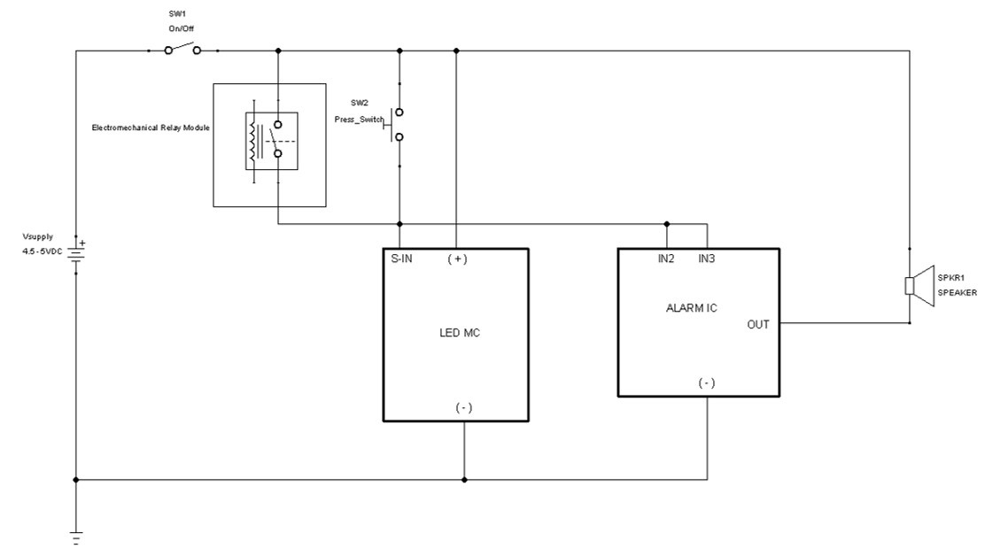
Figure 4.32 – M5Stack controller – electronic circuit schematic diagram of the counting sound device
You will use a pictorial diagram to electrically wire the electrical electronic components of the M5Stack controller counting sound device. The pictorial diagram to aid you in the wiring of the device is shown in Figure 4.33. The unique design of the circuit means that the LED MC does not provide a trigger control signal to the ALARM IC module. The trigger control signal is provided by the momentary pushbutton switch or the electromechanical relay module contacts.

Figure 4.33 – Pictorial wiring diagram for the counting sound device
Quiz 5
In digital electronics, there is an electrical property of electromechanical switches that is disruptive to counting or sequential circuits but provides a unique aesthetic appeal to the LED MC. What is the name of this disruptive electromechanical switch property?
Once you have assembled the M5Stack controller counting sound device, your final project should resemble the picture shown in Figure 4.34:

Figure 4.34 – Final project build of the M5Stack controller counting sound device
As previously discussed in this chapter, mounting putty is used to secure the electromechanical relay module to the Snap Circuits base grid. The M5Stack Core is attached to the Snap Circuits base grid using a LEGO brick and plate. The LEGO brick plate unit is attached to the M5Stack Core. You will attach the M5Stack Core LEGO brick plate unit to the Snap Circuits base grid using mounting putty. Refer to Figure 4.18 for the placement of the mounting putty on the LEGO plate.
The final step to complete the M5Stack controller counting sound device is the UiFlow Blockly software. You will use the alarm circuit software as is, except for a small change to the M5Stack Core UI. The software heading is renamed as Counting Sound Device. The change in UI is shown in Figure 4.35:

Figure 4.35 – Counting Sound Device UI
The UiFlow Blockly code has the same function as for the alarm circuit device project. Therefore, the Blockly code is presented here for convenience:
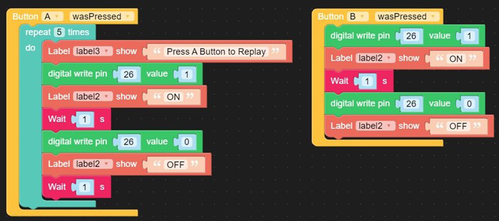
Figure 4.36 – The ALARM circuit device Blockly code
You will press the run button on the UiFlow taskbar to execute the Blockly code on the M5Stack Core. You will see the Counting Sound Device name displayed on the M5Stack Core’s TFT LCD. Figure 4.37 illustrates the functional M5Stack controller counting sound device. Congratulations, you have successfully built an interactive Snap Circuits counting sound device.

Figure 4.37 – Functional M5Stack controller counting sound device
Interactive quiz 3
In reviewing Figure 4.36, true or false – changing the Wait instruction time to 500 ms for the Button A wasPressed code blocks will slow down the LED MC counting sequence?
Congratulations – you have completed the hands-on activities and interactive quizzes in this chapter!
Summary
In the chapter, you learned about the electronic circuits used in the Snap Circuits Arcade Games kit. You learned how to wire electronic circuits using the Snap Circuits modules. You learned about the PICAXE 8-bit microcontroller and its application with the LED MC. You learned that the ALARM IC module has an ASIC. You learned about the workings of the ASIC by building an alarm circuit device. You also learned how to wire an electromechanical relay module to the M5Stack Core. You learned about the technical specifics of the block diagram and how it aligns with an electronic circuit schematic diagram. With this knowledge, you learned how to wire the M5Stack Core to the specific Snap Circuits project using an electromechanical relay.
Furthermore, you learned how to make a programmable controller using the M5Stack Core to operate the LED MC and the ALARM IC module. The LED MC’s Picaxe microcontroller software operates the numbers and letters game. The LED MC’s numbers and letters game is enabled by the M5Stack Core driving the electromechanical relay module’s SPST NO contact. The enabling feature of operating the electromechanical relay module was directed by the M5Stack Core UiFlow Blockly code’s code blocks. The enhancements to the Snap Circuits projects were accomplished using the M5Stack Core programming capabilities to operate port B, which switched the wired electromechanical relay module on and off. In addition, you used your coding knowledge to answer the interactive quizzes through hands-on investigation. Lastly, you explored the repurpose or remix prototyping concept by modifying the alarm circuit code to operate the counting sound device.
In this next chapter, you will take this knowledge of building an M5Stack programmable controller to operate discrete solderless breadboard electronic circuits, a littleBits LED flasher module, and a temperature sensor.
Interactive quiz answers
Quiz 1: Single-Pole, Single-Throw, Normally Closed.
Quiz 2: The white jumper wire provides the control signal to operate the transistor relay driver circuit for the electromechanical relay module.
Quiz 3: The (+) snap pin.
Quiz 4: Switch contact bounce.
Quiz 5: The number 4.
Interactive quiz 1: A machine gun sound.
Interactive quiz 2: False: The 500ms wait instruction will speed up the LED MC counting sequence.