
Chapter 5
Modeling with NURBS Surfaces and Deformers
As you read in the previous chapter, NURBS is based on organic mathematics, which means you can create smooth curves and surfaces. NURBS models can be made of a single surface molded to fit, or they can be a collection of patches connected like a quilt. In any event, NURBS provides ample power for creating smooth surfaces for your models.
Now that you’ve learned the basics of creating and editing poly meshes, getting into NURBS models and more advanced modeling techniques will more easily become part of your toolbox. This chapter explains how to use deformations to adjust a model, as opposed to editing the geometry directly as you did with the previous modeling methods.
- Use the surfacing techniques to create surfaces: Loft, Set Planar, Revolve
- Convert NURBS geometry into polygons
- Create polygon meshes directly from NURBS techniques
- Model an organic shape using NURBS patches
- Create edits to existing models using lattices
NURBS! NURBS!
NURBS is an acronym for Non-Uniform Rational B-Spline. That’s good to know for cocktail parties. NURBS models are typically used for applications in which the rendering is done in advance, such as animation for film or television. NURBS modeling excels at creating curved shapes and lines, so it’s most often used for organic forms such as animals and people, as well as highly detailed cars. These organic shapes are typically created with a quilt of NURBS surfaces, called patches. Patch modeling can be powerful for creating complex shapes such as characters, but can also be tedious and sometimes difficult.
In essence, Bézier curves are created with a starting and an ending control vertex (CV) and usually two or more CVs in between that provide the curvature. As each CV is laid down, the curve or spline tries to go from the previous CV to the next one in the smoothest possible manner.
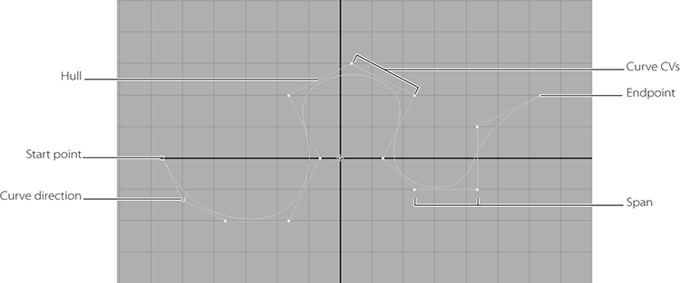
As shown in Figure 5-1, CVs control the curvature. The hulls connect the CVs and are useful for selecting multiple rows of CVs at a time. The starting CV appears in Autodesk® Maya® as a closed box. The second CV, which defines the curve’s direction, is an open box, so you can easily see the direction in which a curve has been created. The curve ends, of course, on the endpoint CV. The start and end CVs are the only CVs that are always actually on the curve.
Figure 5-1: A Bézier curve and its components
NURBS Modeling
NURBS surfaces are defined by curves called isoparms, which are created with CVs. The surface is created between these isoparms to form spans that follow the surface curvature defined by the isoparms, as in Figure 5-2. The more spans, the greater the detail and control over the surface—but this added detail makes greater demands on the computer, especially during rendering.
Figure 5-2: NURBS surfaces are created between isoparms. You can sculpt them by moving their CVs.

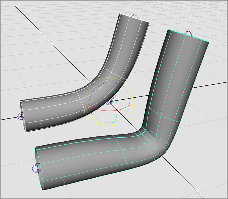
It’s easier to get a smooth deformation on a NURBS surface with few CVs. Achieving the same smooth look on a polygon would take much more surface detail. As you can see in Figure 5-3, NURBS modeling yields a smoother deformation, whereas polygons can become jagged at the edges.
Figure 5-3: A NURBS cylinder (left) and a polygonal cylinder (right) bent into a C shape. The NURBS cylinder remains smooth, and the polygon cylinder shows its edges.

If your model requires smooth curves and organic shapes, use NURBS. You can convert NURBS to polygons at any time, but converting back to NURBS can be tricky.
NURBS surfaces are created by connecting (or spanning) curves. Typical NURBS modeling pipelines first involve the creation of curves that define the edges, outline, paths, and/or boundaries of surfaces.
A surface’s shape is defined by its isoparms. These surface curves, or curves that reside solely on a surface, show the outline of a surface’s shape much as the chicken wire in a wire mesh sculpture does. CVs on the isoparms define and govern the shape of these isoparms just as they would regular curves. Adjusting a NURBS surface involves manipulating the CVs of the object.
Levels of Detail
NURBS is a type of surface in Maya that lets you adjust its detail level at any time to become more or less defined as needed. The display detail keys (1, 2, 3) adjust the level of NURBS detail shown in the panels only.
Press 2, and you’ll see the wireframe mesh get denser. Press 3, and the mesh will get even denser. You can view all NURBS objects, such as this sphere, in three levels of display. Pressing 1, 2, or 3 toggles between detail levels for any selected NURBS object, as shown in Figure 5-4.
Figure 5-4: The degrees of NURBS display smoothness

NURBS Surfacing Techniques
The easiest way to create a NURBS surface is to create a NURBS primitive. You can sculpt the primitive surface by moving its CVs, but you can also cut it apart to create different surface swatches or patches to use as needed, which you’ll see in a steam pump model for an old-fashioned steam locomotive later in this chapter. Using the surfacing tools available under the Surfaces menu set, you can detach, cut, and attach pieces into and out of a primitive to get the exact shapes you need.
You can also make surfaces in several ways without using a primitive. All these methods involve first creating or using existing NURBS curves, or curves on another surface, to define a part or parts of the surface, and then using one of the methods described in the following sections to create the surfaces.
Lofting
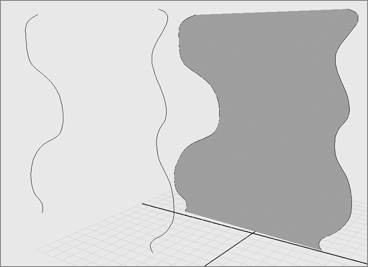
The most common surfacing method is lofting, which takes at least two curves and creates a surface span between each selected curve in the order in which they’re selected. Figure 5-5 shows the result of lofting two curves together.
Figure 5-5: A simple loft created between two curves
To create a loft, follow these steps:
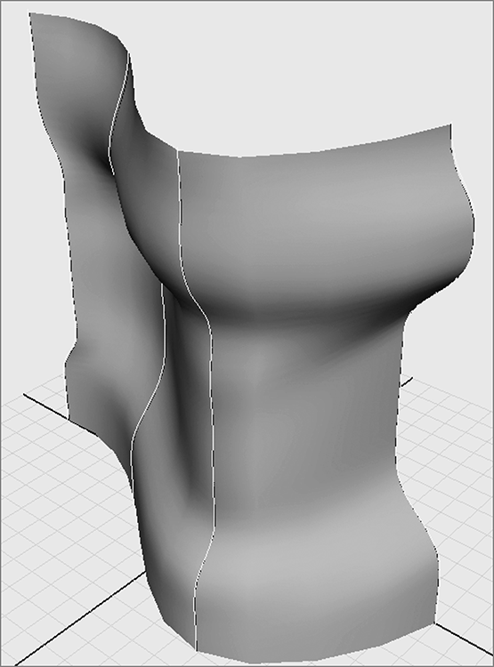
When you define more curves for the loft, Maya can create more complex shapes. The more CVs for each curve, the more isoparms you have, and the more detail in the surface. Figure 5-6 shows how four curves can be lofted together to form a more complex surface. You can use almost any number of curves for a lofted surface.
Figure 5-6: A loft created with four curves that are selected in order from left to right
Lofting works best when curves are drawn as cross-sectional slices of the object to be modeled. Lofting is used to make a variety of surfaces, which may be as simple as tabletops or as complex as human faces.
Revolved Surface
A revolved surface requires only one curve that is turned around a point in space to create a surface, like a woodworker shaping a table leg on a lathe. First you draw a profile curve to create a profile of the desired object, and then you revolve this curve (anywhere from 0 degrees to 360 degrees) around a single point in the scene to create the surface. The profile revolves around the object’s pivot point, which is typically placed at the origin but can be moved (as seen in the solar system exercise in Chapter 2, “Jumping in Headfirst, with Both Feet”), and sweeps a new surface along its way. Figure 5-7 shows the profile curve for a wine glass.
Figure 5-7: A profile curve is drawn in the outline of a wine glass in the Y-axis.

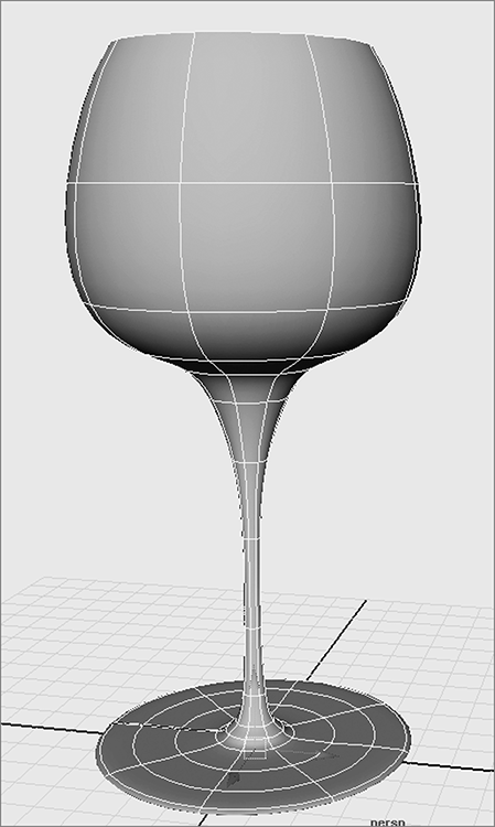
The curve is then revolved around the Y-axis a full 360 degrees to create the wine glass. Figure 5-8 is the complete revolved surface with the profile revolved around the Y-axis.
Figure 5-8: The revolved surface
To create a revolved surface, draw and select your profile curve, and then choose Surfaces ⇒ Revolve.
A revolved surface is useful for creating objects such as bottles, furniture legs, and baseball bats—anything that is symmetrical around an axis.
Extruded Surface
An extruded surface uses two curves: a profile curve and a path curve. The profile curve is drawn to create the profile shape of the desired surface. It’s then swept from one end of the path curve to its other end, creating spans of a surface along its travel. The higher the CV count on each curve, the more detail the surface will have. An extruded surface can also take the profile curve and simply stretch it to a specified distance straight along one direction or axis, doing away with the profile curve. Figure 5-9 shows the profile and path curves, and Figure 5-10 shows the resulting surface after the profile is extruded along the path.
Figure 5-9: The profile curve is drawn in the shape of an I, and the path curve comes up and bends toward the camera.

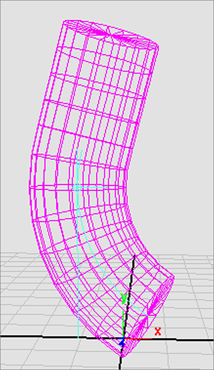
Figure 5-10: After extrusion, the surface becomes a bent I-beam.

To create an extruded surface, follow these steps:
An extruded surface is used to make items such as winding tunnels, coiled garden hoses, springs, and curtains.
Planar Surface
A planar surface uses one perfectly flat curve to make a two-dimensional cap in the shape of that curve. It does so by laying down a NURBS plane (a flat, square NURBS primitive) and carving out the shape of the curve like a cookie cutter. The resulting surface is a perfectly flat, cutout shape, also known as a trimmed surface because the “excess” outside the shape curve is trimmed away.
To create a planar surface, draw and select the curve, and then choose Surfaces ⇒ Planar.
You can also use multiple curves within each other to create a planar surface with holes in it. A simple planar surface is shown on the left side of Figure 5-11. When a second curve is added inside the original curve and both are selected, the planar surface is created with a hole. On the right side is the result when the outer curve is selected first and then the inner curve is selected before choosing Surfaces ⇒ Planar.
Figure 5-11: A planar surface based on a single curve (left); a planar surface based on a curve within a curve to create the cutout (right)

A planar surface is great for flat lettering, for pieces of a marionette doll or paper cutout, or for capping the ends of a hollow extrusion. It’s sometimes best to create the planar surface as a polygon. You’ll see how to convert surfaces to polygons later in this chapter. The following quick exercise will give you an idea of what to look out for when creating polygons from surfacing techniques:
Figure 5-12: Scale the circle up.

Figure 5-13: Choose these options.
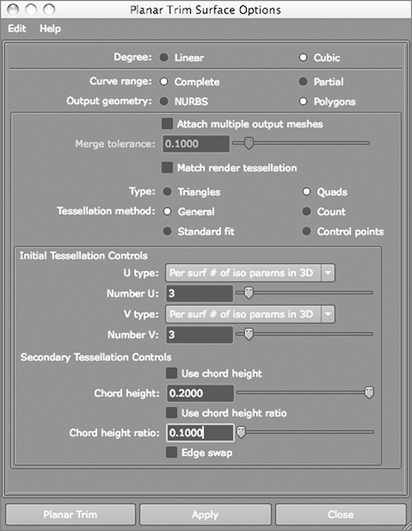
Figure 5-14: Notice the gaps between the outer NURBS circle and the outline.

Keep this exercise in mind as you continue modeling. Whenever you need to create polygons from NURBS surfaces—which should be quite often for some people—try the different creation methods for the best output. No one way works best all the time.
Beveled Surface
The Bevel Surface function takes an open or closed curve and extrudes its outline to create a side surface. It creates a bevel on one or both corners of the resulting surface to create an edge that can be made smooth or sharp (see Figure 5-15). The many options in the Bevel tool allow you to control the size of the bevel and depth of extrusion, giving you great flexibility. When a bevel is created, you can easily cap the bevel with planar surfaces.
Figure 5-15: A curve before and after it’s beveled. The beveled surface has been given a planar cap.
To create a bevel, draw and select your curve, and then choose Surfaces ⇒ Bevel.
Maya also offers a Bevel Plus surface, which has more creation options for advanced bevels. A beveled surface is great for creating 3D lettering, for creating items such as bottle caps or buttons, and for rounding out an object’s edges.
Boundary Surface
A boundary surface is so named because it’s created within the boundaries of three or four surrounding curves. For example, two vertical curves are drawn opposite each other to define the two side edges of the surface. Two horizontal curves are then drawn to define the upper and lower edges. These curves can have depth to them; they need not be flat for the boundary surface to work, unlike a planar surface. Although you can select the curves in any order, it’s best to select them in opposing pairs. In Figure 5-16, four curves are created and arranged to form the edges of a surface to be created. First, select the vertical pair of curves, because they’re opposing pairs; then, select the second two horizontal curves before choosing Surfaces ⇒ Boundary.
Figure 5-16: Four curves arranged to create the edges for a surface (left); the resulting boundary surface formed from the four curves (right)
A boundary surface is useful for creating shapes such as car hoods, fenders, and other formed panels.
Combining Techniques
You can use certain surfacing techniques in combination to create intricate models. For example, whenever a curve is required for a surface, you can use an isoparm instead to create a surface between two existing surfaces.
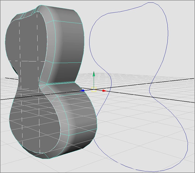
Figure 5-17: Two lofted surfaces with two curves in between
Figure 5-18: Selecting the isoparm
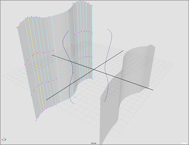
Figure 5-19: The spanning loft between the existing surfaces snakes from the first isoparm to the curves and then to the second isoparm

Surface History
In Chapter 3, “The Autodesk Maya 2014 Interface,” you learned that clicking the History icon (![]() ) toggles History on and off. History has to do with how objects react to change. Leaving History on when creating primitives, as you did in Chapter 2, allows you to access an object’s original parameters.
) toggles History on and off. History has to do with how objects react to change. Leaving History on when creating primitives, as you did in Chapter 2, allows you to access an object’s original parameters.
Leaving History on when creating NURBS surfaces allows the surface to update when any of its creation pieces change. For example, the loft you just created will update whenever the two original surfaces or curves you used to create the loft move or change shape. If you were to move the original loft on the left and rotate it back a bit, the new loft would adjust to keep its one side attached to the same isoparm. If one or more of the input curves were to change, the loft would bend to fit.
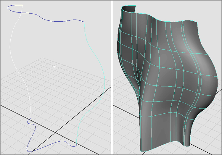
By lofting using isoparms and with History toggled on, you can keep the new surface permanently attached to the original loft, no matter how the isoparms move, as in Figure 5-20. This technique works with all surface techniques, not just with lofting, as long as History is turned on. History is useful for making adjustments and fine-tuning a surface, and it can be handy in animation if several surfaces need to deform but stay attached.
Figure 5-20: History updates the newly created loft to keep it attached to the isoparms and curves used to create it, even when they’ve been moved or altered.

Why wouldn’t you want History turned on for everything? After a long day of modeling, having History on for every single object can slow down your scene file, adding unnecessary bloat to your workflow. But it isn’t typically a problem on most surface types unless the scene is huge, so you should leave it on while you’re still modeling.
If you no longer want a surface or an object to retain its History, you can selectively delete it from the surface. Select the surface, and choose Edit ⇒ Delete By Type ⇒ History. You can also rid the entire scene of History by choosing Edit ⇒ Delete All By Type ⇒ History. Just don’t get them mixed up!
Using NURBS Surfacing to Create Polygons
You can create swatches of polygon surfaces by using NURBS surfacing tools, as you saw during the exercise on creating a planar surface.
To create a polygonal surface with any of the surfacing techniques in this chapter, open the option box for that particular NURBS tool. For example, create two simple curves. With both curves selected, choose Surfaces ⇒ Loft ![]() . In the options for Output Geometry, click the Polygons button to display the options for creating the polygon surface and its detail level.
. In the options for Output Geometry, click the Polygons button to display the options for creating the polygon surface and its detail level.
History for the surface will adjust the new polygonal surface. The detail of the surface will try to adjust as changes to the input curves are made. If you anticipate significant changes to the input curves, make sure you create the poly surface with a high poly count to accommodate major changes. This is probably the best way to create a single poly surface, especially if you prefer a NURBS workflow.
The creation options that appear at the bottom of the window affect the tessellation of the resulting surface; that is, you use them to specify the level of detail and the number of faces with which the surface is created. Generally speaking, the more faces there are, the more detail you’ll need. (That doesn’t mean a detailed surface can’t be efficient, with areas of high tessellation placed only where needed.)
The default Tessellation Method, Standard Fit, uses the fewest faces to create the surface without compromising overall integrity. The sliders adjust the resulting number of faces in order to fit the finer curvature of the input curves.
The lower the Fractional Tolerance setting, the smoother the surface and the greater the number of faces you need.
The Chord Height Ratio determines the amount of curve in a particular region, and calculates how many more faces to use to give an adequate representation of that curved area with polygons. This option is best used with surfaces that have multiple or very intense curves.
It isn’t uncommon to create a surface, undo it, change the slider settings, re-create it, and repeat, to get just the right tessellation. That’s why you should click the Apply button, which keeps the window open, rather than the Loft button, which closes the window after applying the settings.
TheGeneral Tessellation Method creates a specific number of lines, evenly dividing the horizontal (U) and vertical (V) into rows of polygon faces.
The Control Points method tessellates the surface according to the number of points on the input curves. As the number of CVs and spans on the curves increases, so does the number of divisions of polygons.
The Count method simply relies on how many faces you tell it to make—the higher the count, the higher the tessellation on the surface. Experiment with the options to get the best poly surface results.
Converting a NURBS Model to Polygons
Some people prefer to model on NURBS curves and either create poly surfaces or convert to polygons after the entire model is done with NURBS surfaces. Ultimately, you’ll find your own workflow preference, but it helps greatly if you’re comfortable using all surfacing methods. Most modelers choose one way or another but are familiar with both methodologies. In the following section, you’ll convert a NURBS model to polygons.
Open axe_model_v1.mb in the Scenes folder of the Axe project from the companion web page. The toughest part of this simple process is getting the poly model to follow all the curves in the axe with fidelity, so you’ll have to convert parts of the axe differently. Follow these steps:
Figure 5-21: A faithful high-poly conversion (on the right) of a NURBS axe (on the left)
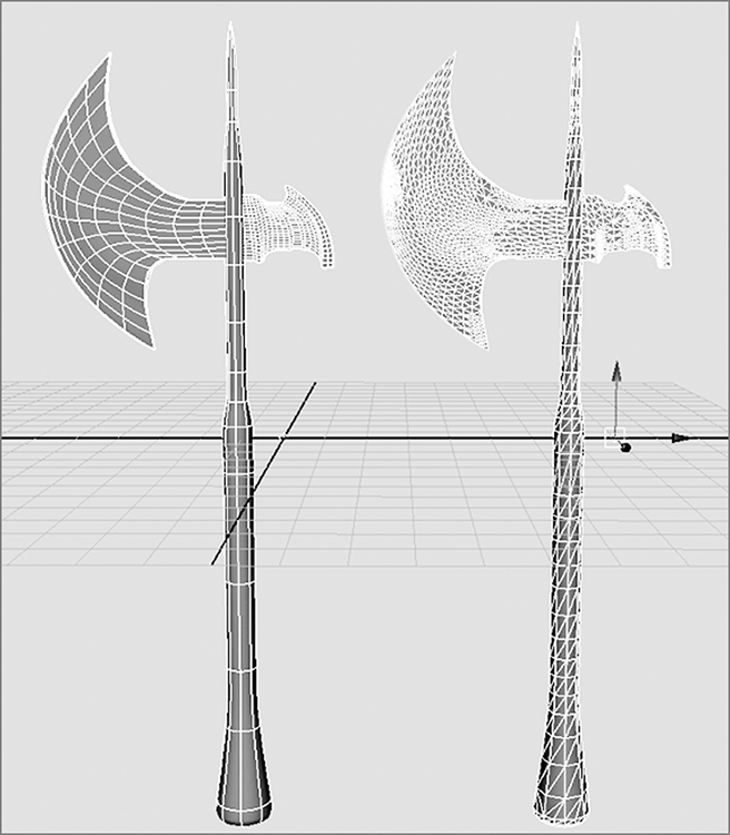
If you were following this process for a conventional game engine, you’d normally be restricted to a low number of polygons, and your axe design would be different to better handle a low poly count.
Editing NURBS Surfaces
As you’ve experienced, Maya provides numerous NURBS tools that you’ll find useful when editing your surfaces. In addition to tools for moving CVs, some important functions and tools allow you to add realism to your model. This section gives you a quick overview of these tools—some you’ve already used, and others you’ll need to try for yourself.
The following functions are all accessed through the Edit NURBS menu. Open and tear off the Edit NURBS menu so it remains open as you follow along.
Project Curve on Surface
The ability to project a curve onto a surface allows you to cut holes in the surface using the Trim tool (choose Edit NURBS ⇒ Trim Tool). It also lets you create, using History, another surface that is attached, following the outline of your projected curve, as you saw in the section “Combining Techniques” earlier in this chapter.
Similar to drawing a curve on a surface, projected curves project an existing curve onto the selected surface. That curve on the surface is now useful for patch modeling as well as tracing animation paths for objects to follow along a surface. For example, you can project a curve around a hilly landscape surface and assign a car to animate (drive) along that projected curve. The car will stick to the surface of the road with ease.
To use Project Curve On Surface, select the surface and the curve to project, and then choose Edit NURBS ⇒ Project Curve On Surface.
Trim and Untrim Surfaces
Trimming a surface (choose Edit NURBS ⇒ Trim Tool) creates holes in the surface using curves that are either drawn or projected onto the surface.
If you have a surface that has already been trimmed and it’s too late to reverse the function with Undo, you can use Untrim Surfaces to remove either the last trim performed or all the surface trims. Choose Edit NURBS ⇒ Untrim Surfaces.
Attach Surfaces
Attach Surfaces does exactly that—it attaches two contiguous NURBS surfaces along two selected isoparms. Select an isoparm on the edge of the first surface, Shift+click an edge isoparm on a second surface, and choose Edit NURBS ⇒ Attach Surfaces to create a new surface from the two. As shown in Figure 5-22, the attach point is along the selected isoparms.
Figure 5-22: Attach Surfaces connects surfaces along their selected isoparms.

Detach Surfaces
Detach Surfaces is a highly useful tool for generating specific areas of a NURBS surface, or patches. Select an isoparm to define the line of detachment, and choose Edit NURBS ⇒ Detach Surfaces. The surface is cut along that isoparm to create two distinct surfaces (see Figure 5-23). You’ll see plenty of Detach and Attach tools later in this chapter.
Figure 5-23: Detach Surfaces cuts a surface at the selected isoparms to create a new surface.

Insert Isoparms
Adding extra surface definition by adding spans is a matter of selecting an isoparm and choosing Edit NURBS ⇒ Insert Isoparms. This creates an isoparm and redefines the surface to add more spans to allow for smoother deformations—for example, adding an isoparm or two to the elbow joint of a model to make the arm bend with a cleaner crease (see Figure 5-24). You can either create a new isoparm between two existing ones or add isoparms to your own defined area.
Figure 5-24: Inserting isoparms for a smoother deformation
Patch Modeling: A Locomotive Detail
With NURBS modeling, you frequently need to attach surfaces so that a model doesn’t split at the seams. This process of aligning and attaching NURBS patches is called stitching, and this kind of modeling is called patch modeling.
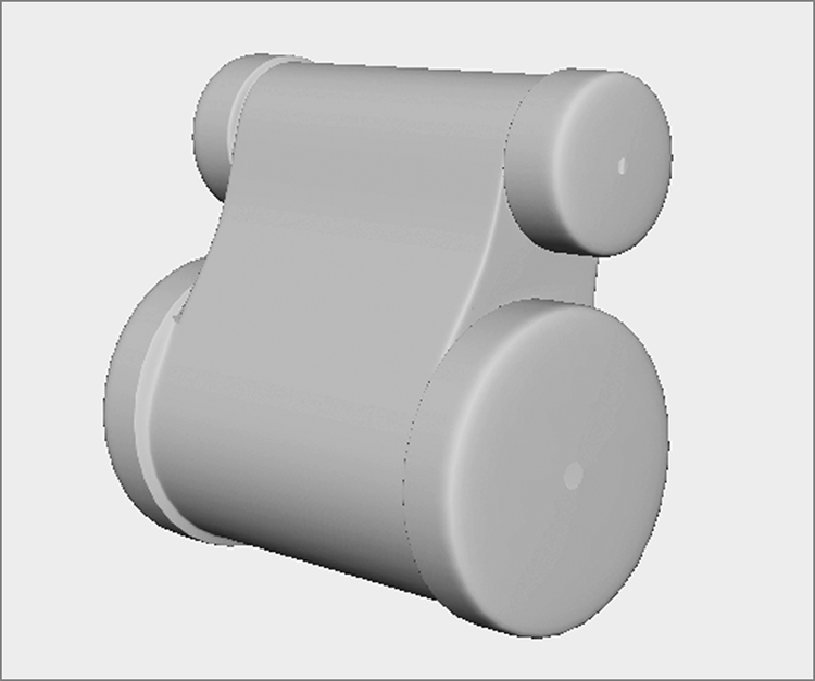
You’re jumping back in time to create a pump for a prebuilt polygonal locomotive. Since this part of the locomotive is perfect for smooth, organic modeling, you will use patches that you’ll stitch together. This exercise gives you an idea of how patches work to pull together an organic shape using NURBS shapes. To show you what you’re seeking to build, the finished model appears in Figure 5-25.
Figure 5-25: The finished pump elements for a classic locomotive model are created in NURBS patches.
Keep in mind that patch modeling is a fairly involved process. If you don’t feel comfortable with modeling quite yet, skip this exercise and move on to the “Using Artisan to Sculpt NURBS” section of this chapter. You can always return to this section to bone up on your patch modeling later.
Starting the NURBS Pump
First, copy the Locomotive project from the companion web page to your hard drive and set it as your current project.
To start creating the locomotive pump, follow these steps:
Figure 5-26: The first NURBS cylinder, after Freeze Transformations
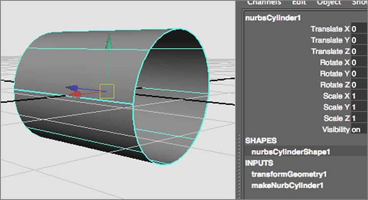
Figure 5-27: Create the end pieces.

Figure 5-28: Create a smaller copy of the first cylinders, and place them higher for the top of the steam pump assembly.
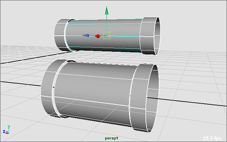
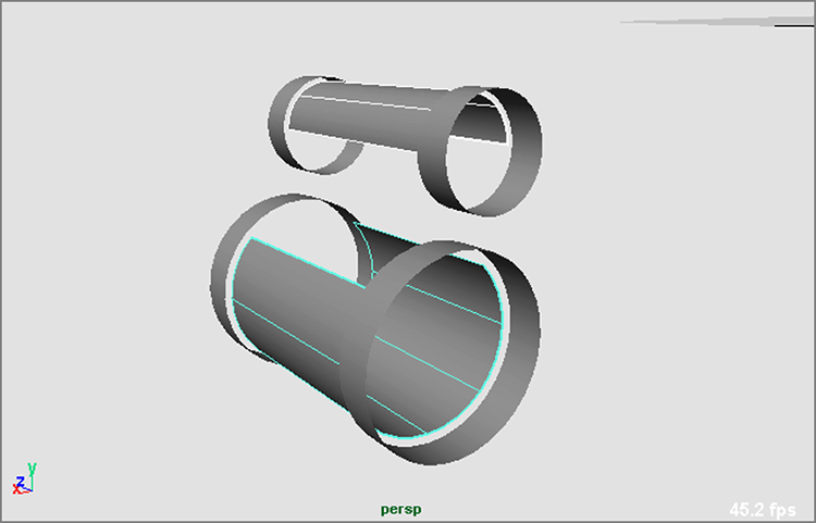
Figure 5-29: Select these isoparms to cut the top of the cylinder.
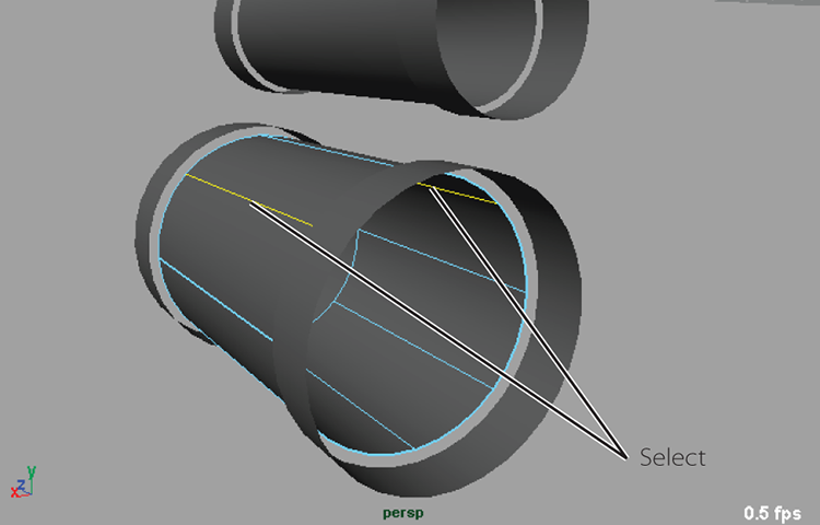
Figure 5-30: Cutting the cylinder’s top
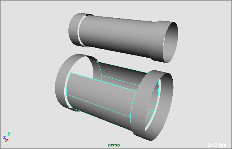
Figure 5-31: The cut cylinders
Adding End Caps
At this point, you’ll cap the ends of the cylinders to close them off. You can continue with your own file or load the file NURBS_pump_v01.mb from the Locomotive project from the companion web page and check your work so far. The trick will be to add four isoparms using the Insert Isoparms function you read about earlier in this chapter to create the caps.
To cap the ends, follow these steps:
Figure 5-32: Select these four isoparms (shown as dashed lines).

Figure 5-33: The default Insert Isoparms Options settings
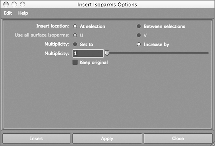
Figure 5-34: Scale down the outermost hull.

Figure 5-35: End caps for the pump pieces
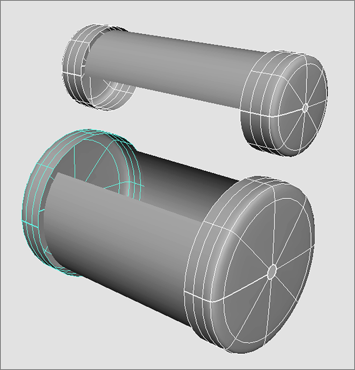
Figure 5-36: Add isoparms as shown here.

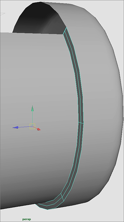
Figure 5-37: Select two isoparms and detach the surfaces.
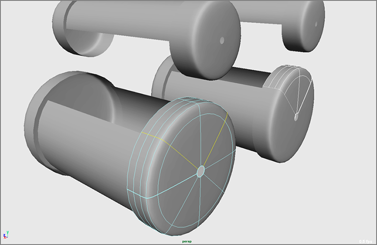
Figure 5-38: Select the four end hulls and move them to line up.
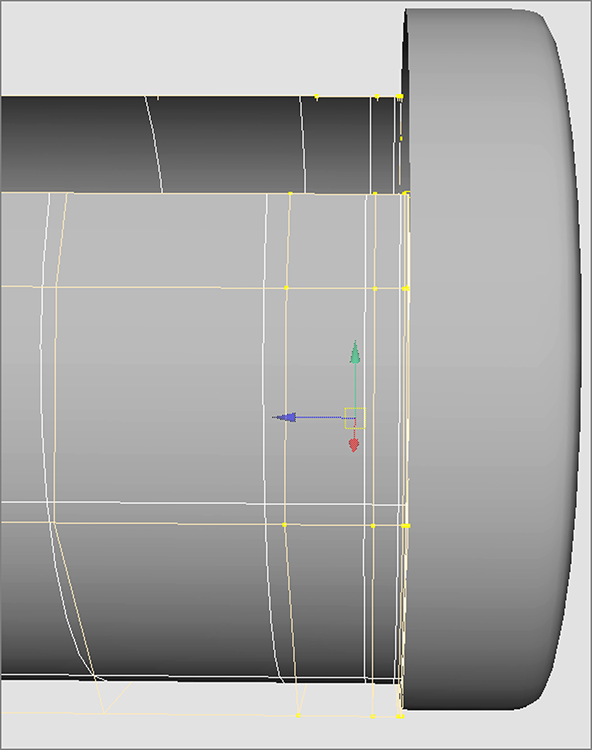
Figure 5-39: Shift+click the edge isoparm.

Figure 5-40: Lofting the end cap to the cylinder
Stitching and Tangency
Smooth seams are essential to organic modeling. The trick for creating a good patch model is to make sure all the patches line up; this is called tangency. In animation and texture setup, it’s important that tangency be correct; otherwise, you may notice tearing at the seams during deformations or texture maps that don’t line up quite right. It can be a tedious process, but here is a taste of it. To continue with the patch model of the locomotive pump, follow these steps:
Figure 5-41: Attach the patches.

Figure 5-42: The end caps attach to the cylinders—smooth as low-cholesterol butter!

Figure 5-43: Lofting the two cylinders together
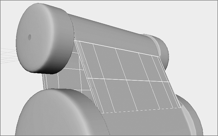
Figure 5-44: Move back the middle and lower-middle hulls.

Figure 5-45: Closing the sides
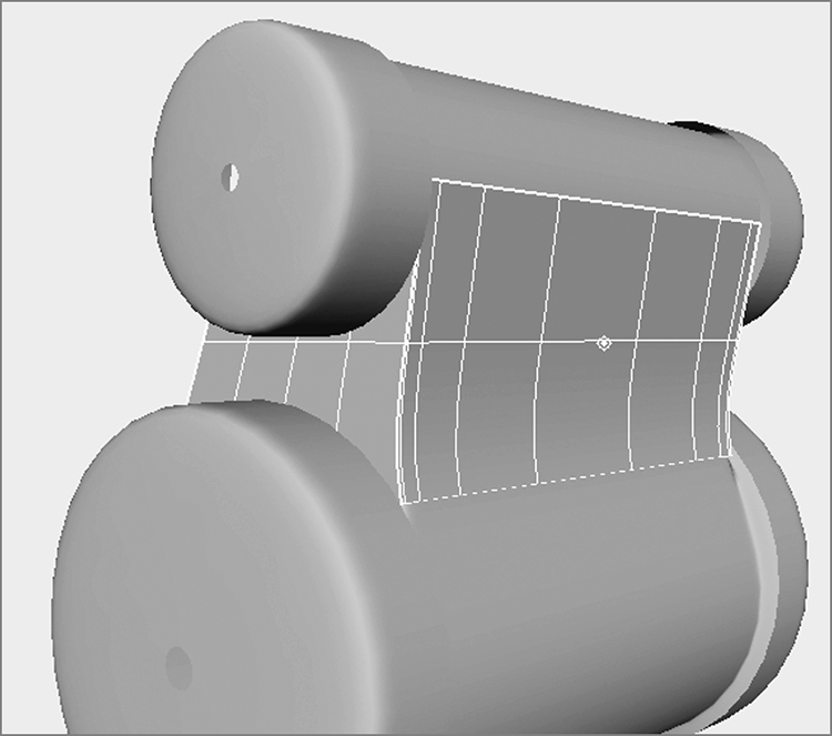
Figure 5-46: In CV mode, line up the ends and cylinders.

Figure 5-47: Create a smooth transition between the surfaces.

Figure 5-48: Insert isoparms into the end cap slice.

Figure 5-49: The groove connecting the end cap with the side panel
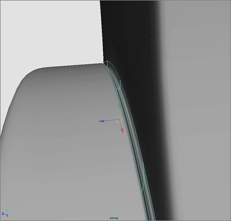
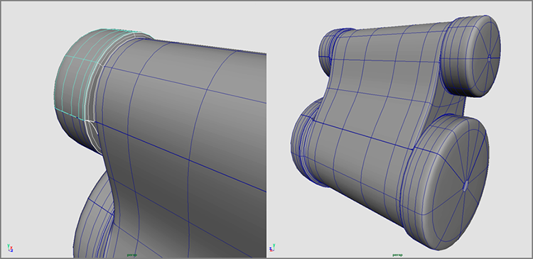
Figure 5-50: Finishing the top part of the NURBS pump (left) and the completed pump (right)
There is quite a bit of lofting, attaching, and detaching between surface patches in patch modeling. The key to becoming good at it is to be able to line up isoparms easily and cleverly and to be able to attach them again smoothly; it takes a lot of practice to get used to this technique. You’ll make a lot of mistakes along the way, but that is how you’ll learn the most! It’s easy to see how this kind of modeling is useful for making organic shapes such as faces.
Integrating the Pump into the Locomotive Model: Importing a Scene
Now that you have the scene completed and saved, let’s insert it into the locomotive model file by importing this saved file. This often happens in CG workflow, where you combine separate scene files into a single file to assemble a larger model. To import your NURBS pump, follow these steps:
Figure 5-51: The locomotive is missing its steam pump (left); place the NURBS pump on to the locomotive (right).
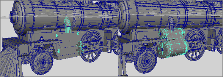
Even though the pump you created is a NURBS model, it will work wonderfully with the polygonal locomotive. You may also opt to convert the surfaces into polygons.
Using Artisan to Sculpt NURBS
Imagine that you can create a NURBS surface and sculpt it using your cursor the way hands mold the surface of wet clay. You can do just that with a Maya module called Artisan—and without the mess!
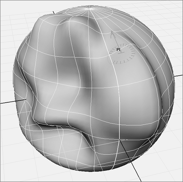
Figure 5-52: The Sculpt Geometry tool lets you mold your surface by painting on it. Here, the brush is set to push in the surface of the sphere as you paint.
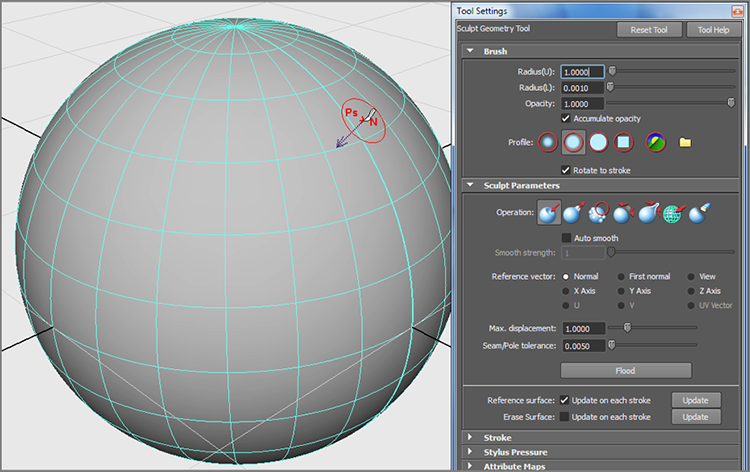
Figure 5-53: With a pull brush, your cursor changes to read Pl.
Additionally, Smooth blends the pushed-in and pulled-out areas of the surface to yield a smoother result. Erase simply erases the deformations on the surface, setting it back to the way it was before.
If you plan to sculpt a more detailed surface, be sure to create the surface with plenty of surface spans and sections. If you want to paint only a specific area of a NURBS surface, choose Edit NURBS ⇒ Insert Isoparms to add extra detail to that area before you begin painting, although you can add isoparms after you paint. When you begin to sculpt this way, going back into the surface’s creation node to increase its sections and spans will ruin your results.
Modeling with Simple Deformers
In many ways, deformers are the Swiss Army knives of Maya animation, except you can’t open a bottle with them. Deformers are handy for creating and editing modeled shapes in Maya. These tools allow you to change the shape of an object easily. Rather than using CVs or vertices to distort or bend an object manually, you can use a deformer to affect the entire object. Popular deformers, such as Bend and Flare, can be powerful tools for adjusting your models quickly and evenly, as you’re about to see.
Nonlinear deformers, such as Bend and Flare, create simple shape adjustments for the attached geometry, such as bending the object. You can also use deformers in animation to create effects or deformations in your objects. We’ll explore this later in the book.
Modeling Using the Bend Deformer
Let’s apply a deformer. In a new Maya scene, you’ll create a polygonal cylinder and bend it to get a quick idea of how deformers work. Follow these steps:
Figure 5-54: Create a cylinder to bend.

Figure 5-55: Creating the Bend deformer

Figure 5-56: Notice the problem with this cylinder?
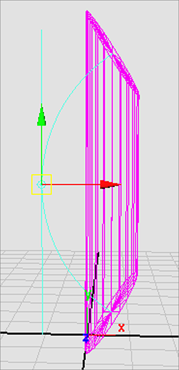
Figure 5-57: Increase Subdivisions Height to 12.

Figure 5-58: The cylinder bends properly now that it has the right number of divisions.
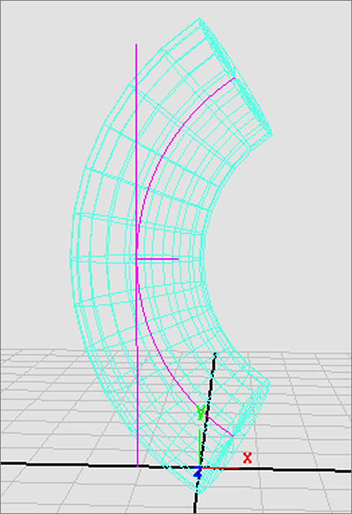
Figure 5-59: Using High Bound to change the effect of the Bend deformer
Experiment with moving the Bend deformer, and see how doing so affects the geometry of the cylinder. The deformer’s position plays an important role in how it shapes an object’s geometry.
Adjusting an Existing Axe Model
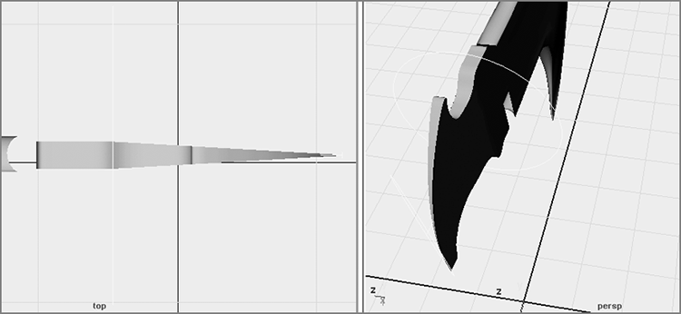
In this exercise, you’ll take an existing NURBS model of an axe and fine-tune the backend of the axe head. In the existing model, the backend of the axe head is blunt, as you can see in Figure 5-60. You’ll need to sharpen the blunt end with a nonlinear deformer. Open the AxeHead_v01.ma file in the Scenes folder of the Axe project from the companion web page, and follow these steps:
Figure 5-60: The axe head is blunt.
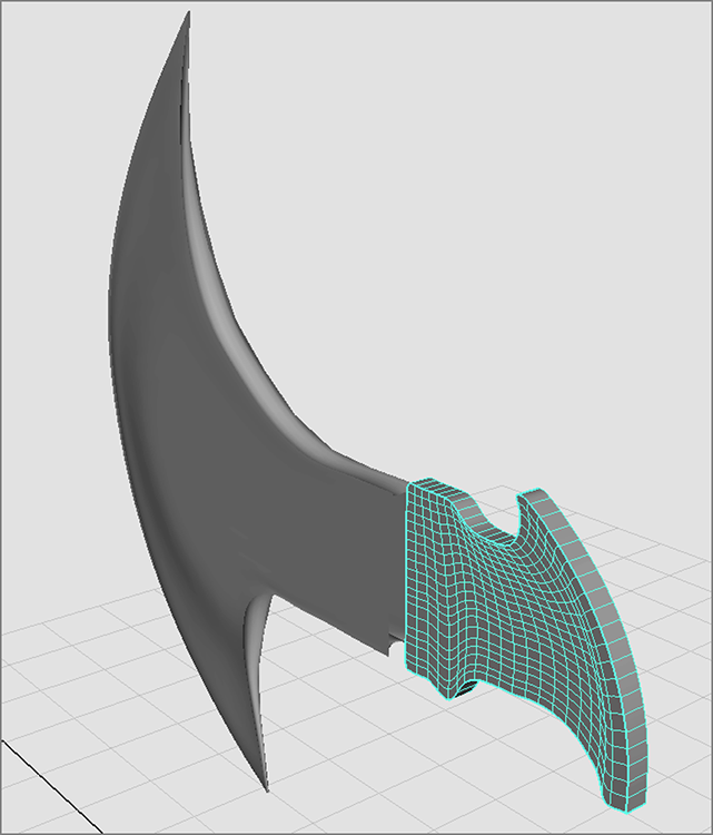
Figure 5-61: Select the back of the axe head.

Figure 5-62: The Flare deformer appears as a cylinder.

Figure 5-63: Rotate the deformer 90 degrees in the Z-axis.

| Attribute | Value |
| Start Flare Z | 0.020 |
| High Bound | 0.50 |
Figure 5-64: Sharpen the axe’s back edge.
Deformers use History to distort the geometry to which they’re attached. You can animate any of the attributes that control the deformer shapes, but in this case you’re using the deformer as a means to adjust a model. When you get the desired shape, as shown in Figure 5-65, you can discard the deformer. However, simply selecting and deleting the deformer will reset the geometry to its original blunt shape. You need to pick the axeHead_Back geometry group (not the deformer) and delete its History by choosing Edit ⇒ Delete By Type ⇒ History.
Figure 5-65: Another view of the back of the axe head with the Flare deformer

The Lattice Deformer
A simple deformer, such as a Bend or Flare, will get you only so far; when a model requires more intricate editing with a deformer, you’ll need to use a lattice.
A lattice is a scaffold that fits around your geometry. The lattice object controls the shape of the geometry. When a lattice point is moved, the lattice smoothly deforms the underlying geometry. The more lattice points, the greater control you have. The more divisions the geometry has, the more smoothly the geometry will deform.
Lattices are especially useful when you need to edit a relatively complex poly mesh or NURBS surface that is too dense to edit efficiently directly with CVs or vertices. With a lattice, you don’t have to move the individual surface points.
Lattices can work on any surface type, and a single lattice can affect multiple surfaces simultaneously. You can also move an object through a lattice (or vice versa) to animate a deformation effect, such as a golf ball sliding through a garden hose.
Creating an Alien Hand
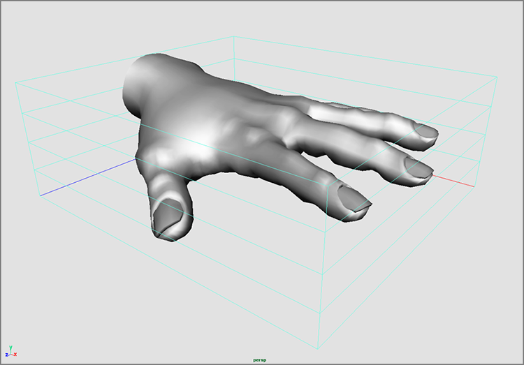
Make sure you’re in the Animation menu set. To adjust an existing model or surface, select the model(s) or applicable groups to deform, and choose Create Deformers ⇒ Lattice. Figure 5-66 shows a polygonal hand model with a default lattice applied. The top node of the hand has been selected and the lattice applied.
Figure 5-66: A lattice is applied to the polygonal hand model.
To experience how this works, you’ll remodel the poly hand using a few different lattices. Your objective is to create an alien hand by thinning and elongating the hand and each of the fingers—we all know aliens have long, gawky fingers. Because it would take a lot of time and effort to achieve this by moving the vertices of the poly mesh itself, using lattices here is ideal.
To elongate and thin the entire hand, load the scene file detailed_poly_hand.ma from the Poly_Hand project from the companion web page, and follow these steps:
Figure 5-67: Changing the number of divisions in the lattice
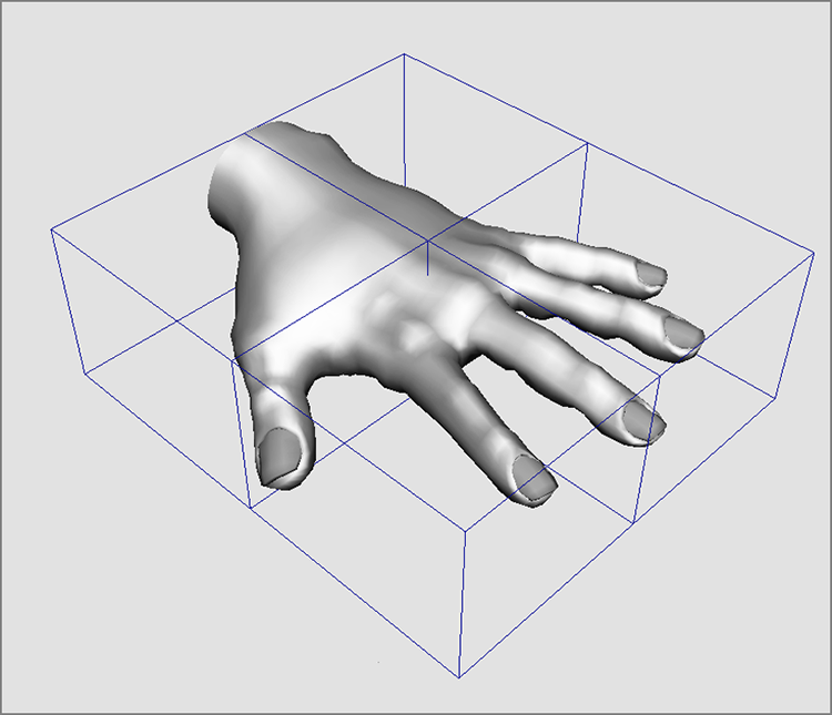
Figure 5-68: Lengthen the hand using the deformer.

Creating Alien Fingers
The next step is to elongate the individual fingers and widen the knuckles. Let’s begin with the index finger. Follow these steps:
Figure 5-69: Select the lattice and base nodes.
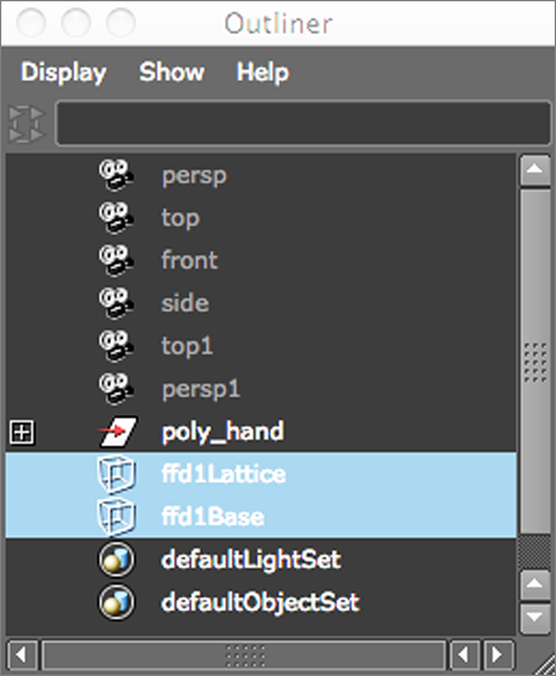
Figure 5-70: Position the lattice and its base to fit around the index finger.
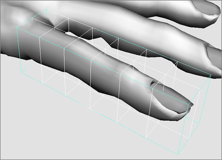
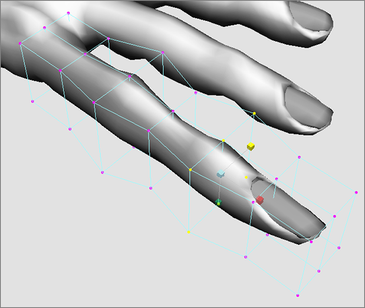
Figure 5-71: Flare out the knuckles.
The alien hand in Figure 5-72 was created by adjusting the polygonal hand from this exercise using only lattices.
Figure 5-72: The human hand model is transformed into an alien hand by using lattices to deform the geometry.

As you can see, lattices give you powerful editing capabilities without the complication of dealing with surface points directly. Lattices can help you reshape an entire complex model quickly or adjust minor details on parts of a larger whole.
In Chapter 8, “Introduction to Animation,” you’ll animate an object using another type of deformer. You’ll also learn how to deform an object along a path.
Animating Through a Lattice
Lattices don’t only work on polygons; they can be used on any geometry in Maya and at any stage in your workflow to create or adjust models. You can also use lattices to create animated effects. In the next exercise, you’ll animate an object through a simple lattice.
In the previous example, if you moved the hand geometry through the lattice while it was still applied to one of the fingers, you would have seen an interesting effect before you deleted the last of your lattices. The parts of the geometry of the hand deformed as the hand traveled through the lattice. Think of ways you can use this warping effect in an animation. For example, you can create the effect of a balloon squeezing through a pipe by animating the balloon geometry through a lattice.
In the following exercise, you’ll create a NURBS sphere with 8 sections and 16 spans and an open-ended NURBS cylinder that has no end caps:
Figure 5-73: Arrange the balloon and pipe.
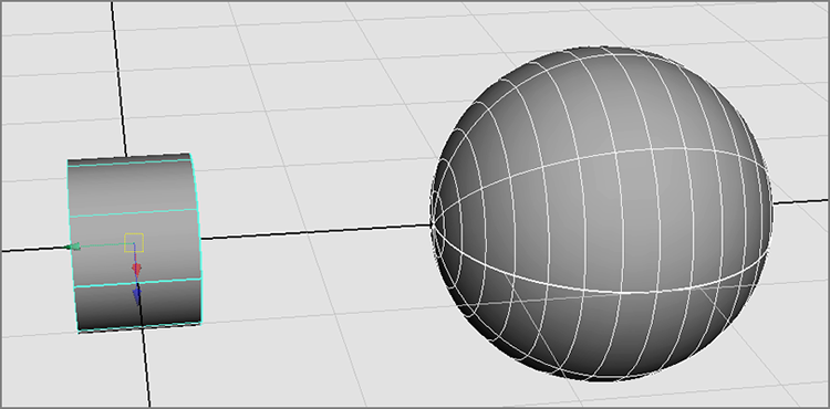
Figure 5-74: Create a lattice for the sphere.
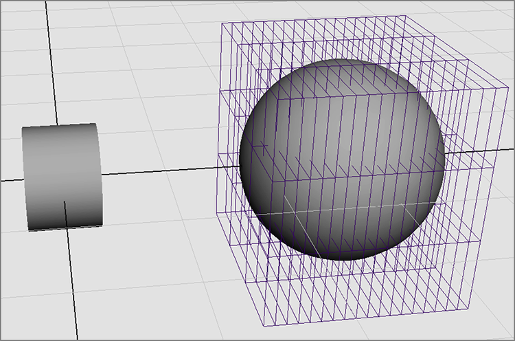
Figure 5-75: Relocate the lattice to the cylinder.

Figure 5-76: Squeeze in the lattice points to fit the cylinder.
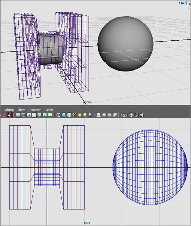
Figure 5-77: Squeezing the balloon through the pipe using a Lattice deformer

In a similar fashion, you can create a lattice along a curve path and have an object travel through it. You’ll try this in Chapter 8.
Summary
In this chapter, you tackled NURBS modeling by going through the usual surfacing tools, from lofting and revolving to bevels and boundary surfaces. Then you explored the implications of surface History, and how surfaces adjust to changes when History is enabled. You learned about different editing methods for NURBS surfaces, such as inserting isoparms and attaching surfaces together as well as converting those surfaces to poly meshes. You then put those lessons to work on creating a NURBS patch model for a steam pump for a locomotive model, which you then imported into the locomotive scene file. Also in this chapter, I introduced you to the Artisan tool and how to use it to sculpt a NURBS surface.
This chapter covered various modeling techniques to help you break away from typical ways of thinking. You learned how to use a lattice to adjust a polygon hand model into an alien hand, as well as how to animate a balloon pushing through a pipe. As you saw in this and in the previous chapter and as you’ll see in the next chapter, you can accomplish a modeling task in several ways. Different workflows give you the flexibility to choose your own modeling style. To make good choices, however, you’ll need to practice. Good modelers have a strong eye for detail and a high tolerance for work that is repetitious. They also love assembling a complex object, and they’re thrilled by the eventual outcome.
Keep at it; model everything you get your hands and eyes on. Try the same model a few different ways; switch between NURBS and polygons to become comfortable with the toolset in Maya. As you’re doing that, stay on top of how you organize your nodes, and keep everything named and organized: the organization of your scenes is extremely important.
For further practice, use this chapter as a reference to create some of the following models using NURBS surfaces and lattices to aid in shaping polygons: