
9
Hand-Talk Assistance: An Application for Hearing and Speech Impaired People
Pradnya Borkar*1, Vijaya Balpande2, Ujjwala Aher3 and Roshani Raut4
1Department of Computer Science and Engineering, Jhulelal Institute of Technology, Nagpur, India
2Department of Computer Science and Engineering, Priyadarshini J.L. College of Engineering, Nagpur, India
3Department of Computer Science and Engineering, Government Polytechnic, Sakoli, India
4Department of Computer Science and Engineering, Pimpri Chinchwad College of Engineering, Pune, India
Abstract
In daily life, disabled persons who are deaf and mute may find it difficult to communicate in society. Some innovative technologies are needed to help mute people communicate with others. There are various technologies that may be used for hearing. The main source of communication is through hand gestures. The hearing person is unable to understand the hand gestures using sign language. Therefore, a technology is required to convert the sign language into audible voice to be understood by hearing people. This chapter describes the hand gesture hearing technology that provides how deaf people will communicate with hearing people. This technology uses the glove with special sensors. The mute person must wear the glove on his or her hand, and as the mute person does various movements by moving hand using sign language, the device intercepts the movement and smartly converts it into voice so that the hearing person can easily understand. The flex sensor pads attached in the glove are useful to sense the movements by detecting various patterns of motion and the pattern in which the curves are made by fingers. The device is designed smartly to sense every resistance and every action carried out by the hands. This chapter also describes the various applications and techniques that may be helpful for the hearing and speech impaired.
Keywords: Hearing and speech impaired, sign language, flex sensor, glove-based system, hand gesture, Hand-Talk assistance
9.1 Introduction
People can have a conversation with each other by exchanging thoughts and ideas. Ideas can be effectively represented through speech. For those who are unable to communicate verbally, they communicate with each other through sign language only. The downside of sign language is restricted to the limited people who are often unable to communicate verbally and, therefore, fall into the category of hearing and speech impaired people.
Individuals who are physically impaired have the privilege to choose what they want to be addressed, either as a community or personally. The persons who are unable to hear prefer to be referred to as “autistic” or “deaf” or “hearing impaired” or “dumb” [1]. Other organizations along with Deaf National Association who are dealing with deaf people use the word “deaf and hard to hear” for these people. Though there are people who use the term other than “deaf and hard to hear”, it is declared as official designation in 1991 by the World Federation of the Deaf (WFD).
The following terminologies are used for hearing and speech impaired people:
- • Hearing-Impaired: A term a lot of most popular by hearing folks, for the most part as a result of they read it as correctness. “Hearing-impaired” is a meaningful word that is a lot of resented by deaf and unable to hear people. Deaf and hard to hear people believe like the words “deaf” and “hard to hear” do not appear to be derogatory in any way.
- □ Deaf and Dumb: A legacy from the medieval English period, this may be the granddad of all misleading marks attached to deaf and hard-hearing people. The Greek philosopher and poet, Aristotle, called himself “hearing and speech impaired” as a result of his feeling that deaf people were unable to be educated, to read, and to think rationally.
- □ Deaf-Mute: Another derogatory word “mute” which means silent together and without a sound rises in the 18th to 19th century. This mark is scientifically incorrect, because the vocal cord of deaf and unable to hear people is working. The point is that your voice is modulated with success; you want to be able to hear your voice.
9.1.1 Sign Language
The communication language between those who are able-bodied and those that are disabled is the sign language. To promote understanding between people, language relies on sign patterns, such as visual contact, orientation, and arm movements. In all, 9.1 billion people were hearing and speech impaired all over the world. They dealt with a slew of additional contact problems in their daily lives. Speech-impaired people use language for the communication. Sign languages include a variety of signals and objects to communicate. They often represent a combination of words and symbols [2].
Sign languages have evolved and are measured at the center of native deaf cultures wherever deaf communities exist. While the deaf use linguistic communication the most, it is often used by others, such as those who can hear but cannot physically talk or have difficulty speaking due to another disability (augmentative and different communication). The vocabulary and descriptive linguistics of sign language differ from country to country. Even within the world, sign language, like spoken languages, varies from region to region.
9.1.1.1 American Sign Language (ASL)
ASL (American linguistic communication) is an intricate language which uses signs formed by hands movement in conjunction with expressions of face and body pose. This is the first language of several hearing-impaired people in North America, and it is one of the communication channels used among people who are visually impaired. The dominant sign language among deaf communities in the United States and most of Northern American hearing-impaired people is ASL. Besides the North America, ASL dialects and ASL-based creoles are spoken in a majority of countries around the world, such as West Africa and Southeast Asia. As a second language, ASL is widely practiced and being used for linguistic communication. The most highly associated marking languages are ASL and French Sign Language. It has been speculated that ASL may have been the Creole language of LSF, regardless of the fact that ASL has properties that are not found in Creole languages, such as agglutinative morphology [3].
9.1.1.2 Comparison of ASL With Verbal Language
Words are created by the use of mouth and speech to form sounds in voice communication.
However, speech sounds are also not perceived by those who are deaf (especially those who are profoundly autistic), and only a fraction of speech sounds are audible on the lips. The belief that vision is the most useful thing a person with a disability has to communicate and collect information has been reiterated.

Figure 9.1 Alphabets in American sign language.
In comparison with English, ASL is a completely new language. It observes that it have its own rules for accent, order of word, and composite grammar, as well as variety of ways of representing various functions, such as instead of an announcement, ask a question. The way this is usually done varies by language. English speakers, for example, lift their voice pitch to ask a question; Users of ASL lift their eyebrows, open their pupils, and turn their bodies forward to express their questions. Basic conduct of communicating thoughts in ASL, like alternative languages, varies as often as ASL users. In addition to voice variations in persons, ASL has regionwise pronunciation and language conversation. Regional variations in ASL singing rhythm, style, and pronunciation exist, despite the fact that bound English words are spoken differently in various parts of the world [4, 5]. Apart from origin and age, there are a slew of other variables that influence ASL use and selection. The alphabet letters in signing is depicted in Figure 9.1.
Like alphabets, gestures are defined for some actions also. Figure 9.2 shows some more combinations of actions.

Figure 9.2 Gestures for movements.
9.1.2 Recognition of Hand Gesture
A gestural movement is described as a communicative movement of body parts. Finger curls and bends produce gestures, which are completely unique postures. Communication is done by gestures. Gestures are a basic prerequisite for developing this device as an input. Hand gestures are of two types: static and dynamic [6].
- • Static: Hand gestures that are not dependent on motion and are fixed in time are known as static hand gestures.
- • Dynamic: Dynamic hand movements are timed hand movements that include the movement of part of your hand. These motions involve movement that is accompanied by a mechanical phenomenon that forms the motion.
9.1.3 Different Techniques for Sign Language Detection
The invention of a system that converts sign language to speech has narrowed the gap between hearing-impaired persons and traditional or normal persons. There are two types of systems such as glove-based and vision-based used to translate sign language into speech.
9.1.3.1 Glove-Based Systems
An individual’s signals during contact are passed to the computer system by wearing gloves on the hands when developing glove-based systems. The information already stored in the database, which was generated initially by storing all types of signs, is compared with the real-time sign. The information gets converted to text and sent to the sound convertor system, in which the data is processed to produce the desired sound [7].
9.1.3.2 Vision-Based Systems
In this system, mostly, a camera is used to map the person’s hand gesture, and then, model matching is performed using feature extraction. It is more complicated than a glove-based system.
Hearing and speech impaired people have always found it difficult to communicate with one another, but they have devised a solution in the form of sign language. Hearing and speech impaired people have a hard time interacting with others. In order to communicate with each choice, each must be able to communicate in the target language, which is often a difficult task. Normal people may connect with hearing and speech impaired people, but it is observed that they feel it difficult to communicate since they are unfamiliar with all of the signs and terminologies [8]. A hearing or speech impaired person’s natural speech speed is quicker than a normal person’s when they learn sign language. In the middle, there should be a method.
9.2 Related Work
Some developers have tried to resolve the problems of hearing and speech impaired people [9] by introducing text to audio converters, interpreters for sign language, and other tools. It has been discovered that there is no single application that combines all of these functions.
Here are some of the applications that have been addressed.
- 1. Computerized Interpreter [10]: The aim of this application was to create a system that would improve communication quality for hearing and speech impaired people. Human-Computer Interaction and Computer-Human Interaction are two-way communication systems. The two basic processes that this system was designed to carry out are as follows.
- □ The sign language gesture is used to recognize the input voice signal and the pictorial representation that goes with it.
- □ A corresponding voice is created as an output by recording the hand gesture.
- 2. Hearing-Impaired Graphical Speech Training System [10]: This application addresses an advanced and Interactive graphic voice training application for hearing-impaired people that have been shown to be cost effective. In the absence of a speech therapist, this computer-based technology often assists autistic children in learning and practicing speaking skills, as well as enhancing responsiveness in deaf children, which helps them to learn and regulate muscular-based activities, which is critical to generate understandable speech for their vocal organs
- 3. Vision-Based Technological Approach: The gesture game is addressed in [11], which was created for deaf people and uses Microsoft Kinect to recognize gesture commands and translate them to text. Another method, called VOM (Voice for the Mute), was developed. This method takes finger spelling as input and translates it into text. In [12], camera was used to create the finger spelling images. The finger spelling is compared to the qualified dataset after image processing and noise reduction. The corresponding text was then translated into voice.
In [13], the author explored the different forms of deaf societies, which were then discussed in [14, 15].
- 1. Hard-of-hearing people: These individuals are partly deaf but can hear. These individuals are also known as culturally marginalized individuals.
- 2. Culturally deaf people: These people can come from a deaf family and uses sign language as their mean mode of communication. It is possible that their speech clarity would be impaired.
- 3. Congenital or prelingual deaf people: Congenital or prelingual deafness refers to deaf people who are born deaf or who are deaf before they learn to speak. Signs may or may not be used by these people to communicate.
- 4. Orally educated or prelingual deaf populace: Deaf people who have been orally taught, also known as prelingual deaf people, were born deaf but gained speech skills later in life.
- 5. Late deafened adults: Adults who have been deaf for a long period of time, these individuals will be able to cope with their gradual hearing loss using communication strategies.
9.3 History and Motivation
Cameras, photographic, infrared, and other imaging devices have been used extensively in this field. To grasp all of these works, you will need a screen in front of you. Recognized hand gestures are another choice. Piezo-resistive sensors can now be used in the design due to technical advances. These sensors are also known as flex sensors because they measure bending. The majority of these sensors can be located in the fingertips. Two biomedical applications for these interfaces are hand prostheses and gesture vocalization. Robotic tele-operation and human-computer interaction tools will also benefit from these interfaces. As a result, an efficient technique for embedding flex sensors in a wearing glove is needed in order to improve sensor accuracy and integrity [16].
9.4 Types of Sensors
In the past, various methods to gesture recognition were used. Vision-based and glove-based methods, as well as colored marker approaches, are the most commonly used gesture recognition technologies. A laptop camera or machine camera is used as the data input device in vision-based techniques to capture information outfitted by various hand and finger movements. The correct locations of hand movements are retrieved in glove-based systems by using data gloves, since their positions are explicitly measured.
9.4.1 Flex Sensor
Flexion sensors, also known as bend sensors, counted how many deflections were caused by bending the sensing device, or sensor (from Latin flectere, “to bend”). Strain gauges1 and hall-effect sensors are two examples of ways to detect deflection [17].
The flexion sensors are of three types:
- 1. Ink-based conductive
- 2. Fiber optic
- 3. Polymer-based conductive
Bend sensing components have an interesting property: bending them to a certain angle at one point cannot be considered as the most helpful use of sensor. The sensor will be permanently damaged or affected if the sensing element is bent more than 90° at one point. Mixture Systems referred the parameter of sensing as “radius multiplied by flex angle”. The sensing parameter was defined by Infusion Systems as “flex angle multiplied by radius”.
9.4.1.1 Flex Sensor’s Specification
Flex sensor is consists of basic specifications as follows:
- • Deflection range
- • Unit vs. bidirectional sensing
- • Unit vs. bipolar sensing
- • Resistance range (nominal to full-deflection)
Deflection Range: The limit or utmost deflection angle that will be evaluated is defined by the deflection range (as against the utmost sensor angle are often bent).
Unit vs. bidirectional sensing: Some of the flexion sensors raise confrontation when it is bent at any two opposite directions, but it is observed that there is no difference between measurement with orientation.
Unit vs. bipolar sensing: This bipolar flexion sensor deviates with two opposite indicators that produce different values.
Resistance range: Bend sensors may have a wide range of resistance (even within the same product) based on the difference between self-reported resistance and maximum resistance.
9.4.1.2 Flex Sensor Types
Conductive ink-based, fiber optic, and conductive fabric/thread/polymer are all examples of flex sensors.
9.4.1.2.1 Conductive Ink-Based
Such bending sensors are idle resistance tools that are usually made by placing on the lower flexible plastic a piece of opposing ink, shaped like a thin, flexible line with a length ranging from 1 to 5.
The bending sensor is defined by internal resistance and rest (when placed on the floor). The opposing elements inside it are pushed forward separately as the sensor is bent. Few neighboring particles are affected, thus increasing resistance. The automatic resistance is usually between 10k and 50k and rises to a maximum deviation by a factor of 10.
The pattern inscribed with the running ink is inside the flex sensor substrates layers. This ink contains carbon, or silver, particles that are combined with a colored machine to make electricity. The particles of carbon are usually suspended in ink to prevent pigment from getting fade. Such ink is safe to use on paper to evade being absorbed by strings, thus altering paper structures. Most of bending sensors which are ink-based available in the market are unipolar alloys, which means that as the deviation rises on one side, the resistance increases and when curved on the other side, it is not altered.
Standing back and forth on two devices will allow bipolar measurement of deviation in both directions. Both of the levels, i.e., hysteresis as well as noise resistance are low; otherwise, they can be completely ignored.
Some flex point Sensors can be of 1”, 2”, and 3” long. They are provided with connectors that can be connected to standardized header’s size. As soon as the length increases, the natural confrontation increases. There are also different ways to attach and cover to raise durability. Piezo-sensing sensors that work with large overlaps (angles angleshulu flex) but at high cost. An example is Bend Short v2.0 which senses bipolar deflection from –180° to +180° [18].
Features:
- • High temperature and humidity tolerance
- • Very low cost
- • Custom (with glass, laminate equipments)
Applications:
- • Vehicle applications
- • Industrial applications, e.g., safety replacement, shipping, and machine control
- • Medical applications (e.g., “Smart bed”)
- • Play equipment
- • Measurement of devices
- • Assistive technology
- • Robots (e.g., ground map and collision detection)
9.4.1.2.2 Fiber Optic
Fiber optic bend sensors also called as optical goniometers contain a light resource (POF) fiber optical plastic with a thermal phase and photosensitive detector. The light is produced from POF on one side and is heard on another side. If the optical fiber bends, then it causes low intensity, i.e., loss of light occurs. This loss can be improved by cutting, polishing, or inserting part of POF5.
The bending sensor can also be made with fiber optic cable with LED and photodiode installed on both sides of the cable section.
Several products uses fiber-optic bend-sensing. Shape Tape, for example, creates completely localized data from the distortion and distortion of data using a series of fiber optic nerve pairs in rubber soles. Each sensor incorporates curvature and reported angular net difference (NAD).
Features:
- • Mainly designed or built laboratory
- • High recurrence, hysteresis is ignored
- • It can bend in either direction
- • Generally unit polar balancing (global flexion)
- • It may be exclusive
Applications:
- • Medical applications
- • Educational courses
9.4.1.2.3 Conductive Fabric or Thread or Polymer-Based Sensor Flexible fabric sensors and cord-based or polymer-based flexion sensors usually consist of double layer material with some opposing material (e.g., Velostat) in between. It is mainly wrapped in heavy layers of material, e.g., Neoprene. By bending or directly, if the pressure is applied, then the two layers of moving substance are pushed together and the sensory resistance decreases. This feeling is similar to strong emotional states. In fact, these types of nerves are pressure sensors that feel deviant, bending the sensor on a part of a solid structure causes the expansion of the nerve to the pressure of the nerve. This is a measure of pressure. Foam/polymer sensors reduce their resistance to name as the material is pressed. These nerves are characterized by abnormalities, recurrence, and hysteresis [19].
Features:
- • Quasilent Equivalent Sensitive Behavior
- • Low reply, due to disability (internal force)
- • High hysteresis, irregularity and recurrence
- • High temperature and humidity (can be used underwater)
Applications:
- • Art projects
The flex sensor differs in resistance when it bends the analog values processed by the microcontroller.
Flex sensors (as shown in Figure 9.3) change resistance depending on the quantity of bending. Here is a Glove Sign Language Glove that will help those who experience any kind of communication problem using gestures, i.e., with the help of one sign language provided to you the user will perform gestures. The powerful sensor will record all movements made by the user and translate these actions into view mode using a program display, as well as audio form using a voice processor.
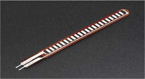
Figure 9.3 Flex sensors.
Usually, a needle and thread are used to attach with the flex sensors. They need a 5-volt input to operate and deliver output between 0 and 5 V. As the angle of bending of the sensor increases, the flexibility of the flexible sensor also increases. The sensor varies with the correct electrical power adjustment.
This change in resistance will be converted into a power conversion by connecting a flexible sensor to a separating circuit. The flex sensor is simply a resistance mechanism and its resistance depends on the width of the bend. Here is the construction of a separation network as shown in Figure 9.4 that may have two resistors. One is a flexible sensor and the other is a 10k resistor. It detects potential reductions in flexibility which means flex sensor and analog electrical power. Analog power is provided by ADC input pins for microcontroller. ADC converts the given analog value into appropriate digital values and stores in the memory of microcontroller. When the amount of electrical energy exceeds the limit value, it is known as input. Two or three sensors are attached in sequence and the sensor generates the output in analog

Figure 9.4 Base flex sensor circuit. which is converted to digital using the digital converter in the controller. The results from the flexible sensors are integrated into the LM258/ LM358 op-amps and used as a setup of a non-installed fashion to maximize their power. Too much bending reduces the effect [20].
In this application, glove is designed to hold the user’s hand. The glove is equipped with sensors with the changing in length of each finger and thumb. Flexible sensors produce a stream of data according to the bending degree. Flex sensors will detect the bending of all fingers. Flex sensor’s nerves are nerves that change resistance according to the nerve bending. They turn the transformation into an electrical resistance—the more you turn, the more resistant you are. Frequency is in line with a thin line from 1“ to 5” of varying lengths of resistance. Here, the flexible sensor is used as a flexible conductor in the region that operates on the principle of a potentiometer that provides various gas energies as a separate resistant release. To measure the curvature of the fingers, flexible sensors are used.
9.4.1.2.4 Arduino Microcontroller
Arduino microcontroller as shown in Figure 9.5 controls all processes and sensory variables as well as Accelerometer.
Arduino Nano is designed for boards, which is based on ATmega328 (Arduino Nano 3.x). Almost the same applies to Arduino Duemilanove, but in somewhat different package. It simply has no DC power, and it uses Mini-B USB cable [21].
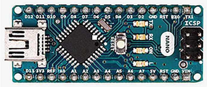
Figure 9.5 Arduino microcontroller.
9.4.1.2.4.1 Power
The Mini-B USB connector is used to power the Arduino Nano, an out-ofsix controller (pin 30), or a 5-V outlet (i.e., pin 27). From the highest power source, the power source is selected.
9.4.1.2.4.2 Memory
Out of 32-KB memory of ATmega328, 2 KB is used for boot. Further, 2 KB is used for SRAM and 1 KB for EEPROM.
9.4.1.2.4.3 Installation and Removal
The input and output is carried out with help of 14 digital pins using the functions of pinMode (), digitalWrite (), and digitalRead (). It operate at 5 volts. Each pin works with a maximum of 40 mA and has an internal pulse, i.e., automatically disconnected of 20–50 kohms.
Some additional features are as follows:
- □ Series: [0 (RX) and 1 (TX)]: It receives (RX) and transfer (TX) TTL serial data. These pins are connected to the compatible connectors of the FTDI USB-to-TTL Serial chip.
- □ External disturbances: (2 and 3): These anchors can be adjusted to cause disruption of the lower value, ups and downs, or price fluctuations.
- □ PWM: (3, 5, 6, 9, 10, and 11): Provide 8-bit PWM output with functionality of analogWrite ().
- □ SPI: 10 (SS), 11 (MOSI), 12 (MISO), and 13 (SCK). These supports the SPI connection.
- □ LED: 13: A digital pin 13 is used to connect to the built-in LED. The LED is switched on, when the pin has high value and when the pin is FULL, LED is turned off. The total analog input pins are 8 for Nano, each of which provides 10 pieces of solution [e.g., automatically measuring from the ground up to 5 volts, but analog Reference () function can be used to change the full end of their range]. Analog anchors 6 and 7 cannot be used as a digital anchor. In addition, some anchors have special functions: I2C: 4 (SDA) and 5 (SCL). Connect the I2C (TWI) connection using the Wire library (documents on the Wiring website) I-AREF. Reliable power of analog input. Used with analog () reference. Reset. Bring this line to reset the controller. It is usually used to add a reset button to the blocking protection on the board.
9.4.1.2.4.4 Communication
Arduino Nano has many computer connections. The serial connection is provided from ATmega328 for the UART TTL (5V), that is provided on digital pins 0 (RX) and 1 (TX).
The FTDI driver that is installed with Arduino software helps for USB communication with the help of FTDI and it provides a com port on computer software. A serial monitor allows the text data transmission to and from the Arduino board. The RX and TX LEDs on the board will light up during data transmission through FTDI chip and the USB connection to the computer.
Software Library allows serial communication on any digital Nano connector. ATmega328 also supports I2C (TWI) communication with SPI. Arduino software includes a Wire library to facilitate the use of the I2C bus. To use the SPI connection, please refer to the ATmega328 datasheet.
9.4.1.2.4.4.1 Default (Software) Reset
As an alternative of having need of material compression (reset button) previous to uploading, Arduino Nano is intended in such a means which accepts it to be reset through software executing on an associated computer. DTR of the FT232RL, one of the hardware controls is connected to the ATmega328 reset line with a 100 nanofarad capacitor. When this line is set (lowered), the reset line drops long enough to reset the chip.
Arduino software utilizes this skill to permit you to download code by just critically using the download button which is near to Arduino area. The boot loader may be short, as DTR reduction may be further intimately connected to loading start. This type of set of connections has other consequences. It resets every time a connection is complete from the software, when a Nano is associated to a computer by means of Linux or Mac OS X. In the second part, the boot loader is trying to work on the Nano.
When new code upload starts, it schedules to ignore the random data upload; once the connection is open, it starts sending the first byte of data to the board. If the drawing uses one time or another data when you start, be sure to have the interactive software wait a while before sending this data once the connection has been reopened.
In recent years, the use of Arduino has increased dramatically due to its readability and simplicity. But the point is to consider whether the use of Arduino is preferred by engineers or not. First, we will look at the benefits of Arduino, and later, we will discuss the disadvantages. Yes there could be evil in Mighty Arduino too [22].

Figure 9.6 American sign language symbols.
9.5 Working of Glove
Capturing hand gestures of the user is the main motto behind the design of this glove. Flex sensors are used to fit inside the glove and this glove is designed to fit depending on the length of thumb as well as each finger. The generated output is the stream which gives the data stream as per the bend of flex sensors. The output generated from the sensors which are in analog format is then fed to the microcontroller. The conversion from analog to digital takes place by processing the signals. The recognition of gesture is carried out after this conversion and the text related to this are spotted out. The sign of particular alphabets should be known to the user. When there is introduction of new sign, it must be added in the database and supported by system.
The flex sensors are attached depends upon the length of the fingers and thumb. The finger’s and thumb’s bending degree generates variation in output voltage which then turned out to voice after converting the analog signals. Likewise, the gloves help speech and hearing impaired people to interact with others in the specified language.
As shown in Figure 9.6, every character and word has a predefined pattern of finger and palm combination. In this chapter, the identification of this pattern or combinations is discussed.
9.5.1 Hand Gloves
As shown in Figure 9.7, the microcontroller and flex sensors are integrated on the gloves. The jumping cables are used to attach these sensors with microcontroller.

Figure 9.7 Hand gloves.
9.5.2 Implementation Details at Server Side
9.5.2.1 Training Mode
Training mode is provided for the user to interact and to update database. Flexibility of insertion of new pattern in database can be done in training mode. As shown in Figure 9.8, First, entered pattern values are checked whether it is already present in database or not. If entered value is already present, then it gives message accordingly; otherwise, it save that word in database.

Figure 9.8 Training mode.
As shown in Figure 9.8, initially, the color of all fingers will be green, after bending the right thumb and index finger of right hand, the color was changed and becomes red. The string appears as 0000011000. The string which is appeared on the screen is already stored in the database for the word “Nice”. After identifying word, text was converted into speech. Some threshold value need to set to identity the bending of the fingers. So, the threshold is set as 750 kohms, i.e., if the threshold value of flex sensors is found to be greater than 750 kohms, then it specify that the flex sensor is not bent, but if the threshold is less than 750 kohms, then it shows bending of flex sensors and the signal turns to red.
9.5.2.2 Detection Mode
In detection mode, the pattern is used to compare to a previously saved pattern in the database by using the microcontroller’s input and a combination of those inputs. If the pattern is found in the database, then it will be marked as available; otherwise, it will be marked as unavailable.
9.5.2.3 Text to Speech
After detection, the text-to-speech conversion takes place and this detected word get converted into audible format. Here, the following steps are followed.
Sign □ Word □ Speech.
Microsoft Windows operating system provides an application program interface (API) called as SAPI (Speech Application Program Interface). This API allows the speech recognition capabilities, and it allows to write the program that provides text-to-speech conversion. SAPI has the following main modules:
- 1. Voice Command: For applications, this module offers command for control speech recognition. This module facilitates to build a menu of voice commands that includes voice commands such as new file and send mail. After enabling the module, the user would be able to use the device without using a keyboard or mouse.
- 2. Dictation of Voice: This module helps a user to dictate voice through a speech recognition program. The virtual editor box receives and shows the text that the user dictates in an application window. This module allows you to format text in a variety of ways, including converting punctuation words to punctuation marks, modifying the case of letters in the alphabet, and correcting the last word spoken or a set of words.
- 3. Voice Text: Voice Text translates text into speech that can be listened to on a device or sent over the internet. There are several different types of speech being played, each with a different accent.
- 4. Voice Telephony: This module makes use of telephony controls that are close to those used in Windows. The controls on a window are made up of keys, sliders, list boxes, and other items that can be moved around with the help of mouse or keyboard. Some other codes called as Telephony controls identifies spoken answers like Yes or No, other details such as time, date as well as phone number. Telephony controls enable the user to communicate with the device. For example, when user calls a vendor to order an item. The user want to know about several things by speaking into the telephone receiver. Instead of processing these manually, these responses are recognized by telephony controls and these responses are transferred to the processing response applications. This module also manages error conditions.
- 5. Direct Speech Recognition: This interface is somewhat same to the voice command at low level. The difference is that this module directly speaks to the speech engine.
- 6. Direct Text To Speech: This interface is similar to voice-text and it also speaks directly to search engine.
- 7. Audio Objects: Specifically, where there is audio, it is done by an audio object.
9.6 Architecture
Figure 9.9a shows the architecture of the overall system, the left and right hand glove connected with microcontroller, the microcontroller connected with server, and on other hand, server is also connected with software of pattern matching (including database).
To recognize the alphabets of sign language, the flowchart depicts the steps as shown in Figure 9.10. Once the device is switched on, the sensors are regulated and the microcontroller receives the readings from the sensors. Depending on the values generated by bending the glove, that value is matched with the values stored in the database. If it is matched, then the related word is displayed and accordingly it is spoken out. In the training mode, the user can insert new patterns in the database, whenever that pattern is inserted, it is first checked in the database whether it is already present or not, if it is not present, then it will be stored in the database otherwise discarded.

Figure 9.9 (a) System architecture (basic block of communication).

Figure 9.9 (b) System architecture (gloves interfacing with microcontroller).

Figure 9.9 (c) System architecture (with pattern matching feature).
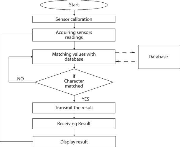
Figure 9.10 Flow diagram.
In the detection mode (Figure 9.11), the matched word is displayed but before displaying it needs to check in the database and convert it to speech, But if it is not available, then it shows “Not Available”.
The values in Figure 9.12 shows the resistance value of the flex sensor and the green color indicate that finger is not bend and it sends integer value 0 in database; if the finger is bend, then the color becomes red and it sends integer value 1 in the database.

Figure 9.11 Detection mode.
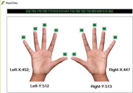
Figure 9.12 Values and signal obtained.
9.7 Advantages and Applications
Advantages
- • Efficient way for mute communication.
- • System is portable and flexible to users.
- • It takes less power to operate the system.
- • Easy to define gestures: Users can add their own gestures.
- • Less time delay for conversation.
- • Quick response time.
- • Fully automated system.
Applications
- • Loud Venue: A place like a pub, a building site, or a rock festival where there is so much crowd noise to have a regular conversation with people. Use ASL, it can quickly converse from a distance, no matter how much background noise there is. Users may also use earplugs to shield their ears and also talk just fine.
- • Injury Recovery or After Surgery: Certain surgical operations (such as oral surgery) impair a person’s ability to speak during recovery. People can interact with ASL without having to speak. Event Stage Squad or Teams of people employed in music, theater, or related environments benefit from being able to communicate over distances without shouting.
- • Video Production: Working on a film collaboration alongside a few people at a big case. ASL users can chat quietly with other people from behind the camera and do not produce background conversation sounds that will interfere with video capture. Users can also communicate in a busy, noisy space without yelling.
- • Radio Station: Users are in a radio station sound room with many people taking part in a live chat show. ASL users can connect with others on a live recording without talking or interrupting the broadcast.
- • Military Operations: Users are delegated to special ops and required to stay fully quiet (including radio silence). Users of ASL can interact clearly with other members of the team. You can talk effectively over longer distances with binoculars.
References
1. Sharma, K. and Garg, N.K., Hand Gestures Recognition for Deaf and Dumb. Int. J. Comput. Appl. Technol. (s), Vol. 11, 10–13, May - 2014.
2. Shohaib Ahmed, V., MAGIC GLOVES (Hand Gesture Recognition and Voice Conversion System for Differentially Able Dumb People). Tech Expo-The Global Summit, London, 2012.
3. Tiwari, D. and Srivastava, S.K., A Visual Recognition of Static Hand Gestures in Indian Sign Language based on Kohonen Self-Organizing Map Algorithm. Int. J. Eng. Adv. Technol.(IJEAT), 2, 165–170, Dec 2012.
4. Zhang, X., Chen, X., Li, Y., Lantz, V., Wang, K., Yang, J., A Framework for Hand Gesture Recognition Based on Accelerometer and EMG Sensors. IEEE Trans. Syst. Man Cybern.—Part A: Syst. Hum., 41, 6, pp. No. 1064–1076, November 2011.
5. Heo, H., Lee, E.C., Park, K.R., Kim, C.J., Chang, M., A Realistic Game System Using MultiModal User Interfaces. IEEE Trans. Consum. Electron., 56, 3, pp. 1364–1372, August 2010.
6. Alon, J., Athitsos, V., Yuan, Q., Sclaroff, S., A Unified Framework for Gesture Recognition and Spatiotemporal Gesture Segmentation. IEEE Trans. Pattern Anal. Mach. Intell., 31, 9, pp. 1685–1699, September 2009.
7. Kosmidou, V.E. and Hadjileontiadis, L.J., Sign Language Recognition Using Intrinsic-Mode Sample Entropy on sEMG and Accelerometer Data. IEEE Trans. Biomed. Eng., 56, 12, pp. 2879–2890, December 2009.
8. Dipietro, L., Sabatini, A.M., Dario, P., A Survey of Glove-Based Systems and Their Applications. IEEE Trans. Syst. Man Cybern.—Part C: Appl. Rev., 38, 4, pp 461–482, July 2008.
9. Advani, N., Bora, S., Bhat, A., Yerolkar, S., A Survey on Communication Gap between Hearing and Speech Impaired Persons and Normal Persons. IJCSN Int. J. Comput. Sci. Netw., 2, 6, December 2013.
10. Suresh, P., Vasudevan, N., Ananthanarayanan, N., Computer-aided Interpreter for Hearing and Speech Impaired, in: 2012 Fourth International Conference on Computational Intelligence, Communication Systems and Networks, https://www.infona.pl/resource/bwmeta1.element.ieee-pub-000006273236/ tab/summary.
11. CSO-MDS-2012, Manual on disablity statistics, Government of India, Ministry of Statistics and Programme Implementation, New Delhi, www. mospi.gov.in, 2012.
12. Tripathy, A.K., Jadhav, D., Barreto, S.A., Rasquinha, D., Mathew, S.S., Voice for themute, in: Proceedings of the 2015 International Conference on Technologies for Sustainable Development, ICTSD 2015, February 2015.
13. Yousaf, K., Mehmood, Z., Saba, T. et al., A Novel Technique for Speech Recognition and Visualization Based Mobile Application to Support Two-Way Communication between Deaf-Mute and Normal peoples. Hindawi Wirel. Commun. Mob. Comput., Article ID 1013234, 12 Pages, 2018, https://doi.org/10.1155/2018/1013234.
14. Pray, J.L. and Jordan, I.K., The deaf community and culture at a crossroads: Issues and challenges. J. Soc. Work Disabil. Rehabil., 9, 2, 168–193, 2010.
15. Barnett, S., Communication with deaf and hard-of-hearing people: A guide for medical education. Acad. Med.: J. Assoc. Am. Med. Coll., 77, 7, 694–700, 2002.
16. Karlsson, N., Karlsson, B., Wide, P., A Glove Equipped with Finger Flexion Sensors as a Command Generator used in a Fuzzy Control System. IEEE Trans. Instrum. Meas., 47, 5, October 1998.
17. Starner, T., Weaver, J., Pentland, A., Real-Time American Sign Language Recognition Using Desk and Wearable Computer Based Video. IEEE Trans. Pattern Anal. Mach. Intell., 20, 12, 1371–1375, Dec. 1998.
18. Gujrati, A., Singh, K., Khushboo, Soral, L., Ambikapathy, Hand-talk Gloves with Flex Sensor: A Review. Int. J. Eng. Sci. Invent., 2, 4, 43–46, April 2013.
19. Bretzner, L. and Lindeberg, T., Relative orientation from extended sequences of sparse point and line correspondences using the affine trifocal tensor, in: Proc. 5th Eur. Conf. Computer Vision, vol. 1406, Lecture Notes in Computer Science, Springer Verlag, Berlin, Germany, 1998.
20. Fels, S.S. and Hinton, G.E., — Glove-talk: A neural network interface between a data glove and a speech synthesizer. IEEE Trans. Neural Networks, 4, l, 2–8, 1993.
21. Freeman, W.T. and Weissman, C.D., TV control by hand gestures. Presented at the IEEE Int. Workshop on Automatic Face and Gesture Recognition, Zurich, Switzerland, 1995.
22. Fu, K.S., Syntactic Recognition in Character Recognition, p. 112, Academic, New York, 1974, Mathematics in Science and Engineering.
- * Corresponding author: [email protected]