
A Risk-Based Approach to Scale-Up of Amine Absorption Processes for CO2 Capture and Storage
Hamidreza Bakhtiary-Davijany and Tore Myhrvold, DNV Research & Innovation, Det Norske Veritas AS, Høvik, Norway
8.1 Introduction
Carbon capture and storage (CCS) is an important component of low-carbon technologies for climate change mitigation. The Global CCS Institute suggests a definition for CCS as the long-term isolation of fossil fuel CO2 emissions from the atmosphere through capturing and storing the CO2 deep in the subsurface of the Earth. Carbon capture is the separation of CO2 from the other gases produced when fossil fuels are burnt for power generation and when CO2 is produced in other industrial processes. Once separated, the CO2 is compressed and transported to a suitable site for geological storage. At its storage site, CO2 is injected into deep underground rock formations, often at depths of 1 km or more below the seabed (Global CCS Institute, 2012).
CCS is currently used in a number of industries and as of today, eight large-scale CCS projects are storing about 23 million tonnes (MT) of CO2 each year. With a number of projects currently under construction (including two in the electricity generation sector), this figure will increase to over 36 MT of CO2 per year by 2015 (Global CCS Institute, 2012). However, lack of funding has, in the recent years, led to the cancellation of a number of planned large-scale CCS demonstration projects. Extensive governmental support is therefore required for CCS projects to continue to the operational phase. Moreover, reducing the cost of technology through demonstration projects is crucial. Commercial scale demonstration of CO2 capture technology requires application at increasing scales with integration into an industrial process or power station.
8.1.1 Overview of the Amine Absorption Process Technology
There are three major concepts for capturing CO2 from the combustion of fossil fuels and/or biomass: post-combustion capture (PCC), pre-combustion capture and oxy-fuel combustion capture. Within each of these three concepts there are multiple alternative pathways utilising various solvents, adsorbents or membranes. Post-combustion CO2 capture using an amine or a mixture of amines as solvent is currently the commercially leading technology for CCS application, particularly for retrofitting existing power plants.
Chemical absorption processes are based on a solvent that dissolves the CO2 into a liquid. The absorbed CO2 is then released by changing the temperature and/or pressure. A schematic of a solvent-based PCC process is shown in Figure 8.1. The flue gas (exhaust gas from the power plant) usually has a temperature range of 40–60°C (Oyenekan and Rochelle, 2006) where it is fed to the bottom of the absorber packed column. The lean solvent enters the top of the absorber where CO2 from the flue gas is removed via a physical–chemical interaction. The CO2-rich solvent leaves the absorber bottom while the treated flue gas exits from the absorber top towards the stack. In the desorber column (stripper), CO2 is stripped off from the rich solvent via a thermal process at 100–120°C (Aaron and Tsouris, 2005). The lean solvent is recycled to the absorber again while a CO2 stream is sent to the compression unit.
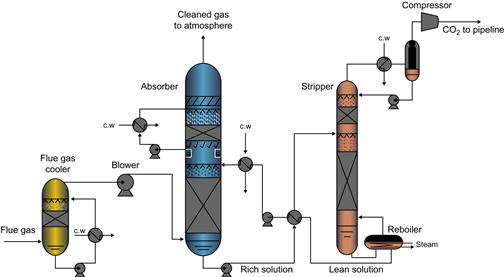
Figure 8.1 Typical amine-based chemical absorption process (Tobiesen, 2006).
Many industries have been using CO2 capture processes commercially for more than half a century, mainly for cleaning and processing of gas streams other than flue gas. Amine absorption for CO2 separation has for instance been applied for natural gas sweetening as well as in the food and beverage industry, where CO2 is used as raw material or released to the atmosphere. Among the vendors currently offering this technology are Fluor and Mitsubishi Heavy Industries, BASF/Linde and CB&I Lummus. There are also several vendors developing new technologies for CO2 capture such as Alstom, Aker Clean Carbon (ACC), Siemens, Shell (Cansolv Technologies), Huaneng-CERI Powerspan and HTC Pure Energy.
For CCS applications, CO2 is captured from natural gas sweetening plants and is stored in geological formations. Examples of this are the Sleipner project in the North Sea (Norway) which has been in operation by Statoil since 1996, the Snøhvit LNG plant (Norway) with CO2 capture and storage in the North Sea as well as BP’s in Salah gas processing plant in Algeria. All these three examples have applied amine-based chemical absorption technology for CO2 separation (Folger, 2010).
8.1.2 Status and Outlook for CO2 Capture Process Development
The zero emission platform (ZEP, 2006) previously reported that consecutive scale-up, validation and verification work is necessary for the development of large-scale industrial processes. However, according to the Global CCS Institute (2012), large-scale integrated projects have experienced some setbacks during the past years.
As of today, there is no operating full-scale commercial process capturing CO2 from power plant flue gases. There is however one large-scale plant currently under construction and scheduled to be in operation in 2014. The SaskPower Boundary Dam retrofit project plans on capturing 1.0 MT per year and intends to sell CO2 for enhanced oil recovery. In addition, there are a number of projects under development ranging from laboratory scale to pilot scale and up to demonstration scale (e.g. Technology Centre Mongstad, TCM) worldwide.
Today, industry is practicing the use of process modelling and simulation as a tool for design and scale-up of CO2 absorption processes as an integrated part of process development and piloting. The rate-based models provided through commercial or in-house packages used in conjunction with data from suppliers on their specific process unit components, e.g. packing materials, are able to provide a good basis for design and scale-up of the process both at detailed equipment level and at the process plant level.
With the common goal of reducing the high cost of CO2 capture resulting from its large energy consumption, the focus of these projects is mainly on development of new chemical processes, new process designs and novel power plant integration schemes (e.g. waste heat and heat recovery). A vast number of recent publications are therefore focused on the cost and performance of CO2 capture processes. However, it is a difficult task to investigate the suitability of a certain amine absorption process for a specific application only based on publically available information. This is due to many reasons such as complexity, limited details provided in the published information and differences in the definitions of key performance indicators.
In addition, a clear analysis of the different steps to be undertaken in order to bring a promising new technology to commercial reality is required. The objective of such an assessment would be the technical, economic, environmental and safety risks associated with large-scale deployment of the technology.
8.1.3 Rationale and Overview
This chapter presents a method for risk-based qualification of large-scale CO2 absorption processes for CCS applications with a focus on ‘process scale-up’. The method is based on Det Norske Veritas’ (DNV’s) Technology Qualification (TQ) procedures which aim at managing the challenges posed by the residing uncertainties in the design and performance predictions of new technologies at commercial scale. TQ is a specific type of assessment performed in many industries, e.g. the energy sector, to verify that a new technology will work as intended. TQ aims at demonstrating with an acceptable level of confidence that a new technology will function within specified limits. This is done, for instance, by provision of documented evidences that commercial objectives, such as CO2 captured, power consumed, pollutants emitted, waste created, water consumed, etc., are achieved at the commercial scale. Moreover, the method can also be used to qualify specific novel techniques for energy consumption optimisation such as intercooling in the absorber, etc. Achieving this is inevitably much more difficult for an immature technology than for a mature technology. However, the challenge (and where the economic opportunities lie) is to foresee as early as possible in the development of a new process exactly what tests are ultimately needed (and spend resources on those only) thus avoiding spending time and money on expensive tests that are not needed.
This leads to the main rationale behind the methodology where a risk-based approach to the scale-up provides a cost-efficient, safe and environmentally friendly process development. DNV has previously presented guidelines for qualification of CO2 capture technology (Myhrvold et al., 2009). This was later developed into a DNV-recommended practice (DNV, 2010b). DNV has also previously discussed some generic issues related to TQ and process scale-up (Johnsen et al., 2009). More recent, Hessen et al. (2012) presented and discussed the use of rigorous process modelling as a tool in TQ and scale-up to create confidence in design and performance predictions, whereas Bakhtiary-Davijany and Myhrvold (2012) gave an introduction to using TQ for maturity assessment of CO2 capture processes.
The following sections present the risk-based approach and highlights issues relevant to employing the procedure for amine absorption processes. Challenges associated with the different process development stages for amine absorption processes are also discussed. In the following sections, first a literature review of published methods for scale-up of the amine absorption process is presented. Then the risk-based qualification method is introduced and a case study giving examples of typical scale-up challenges dealt with in a systematic way using this methodology is presented and discussed.
8.2 Scale-Up of Amine Absorption Processes for CCS
Scaling up chemical processes is an essential task for chemical engineers and is the fundamental step in the realisation and optimisation of commercial plants. The scale-up task includes the synthesis of know-how accumulated in the various phases of process development from the design of laboratory experiments and kinetic rate measurement to hydrodynamic and thermodynamic experiments, mathematical modelling, design and operation of pilot and semi-commercial plants (Donati and Paludetto, 1997). There is no exact and well-established rule for scale-up and for arriving at successful operation of large-scale processes. It is usually a result of gathering technical know-how through process development coupled with successful decisions and some times of many unsuccessful attempts. Scale-up is an interdisciplinary effort achieved by a team of individuals operating with a common goal. One major threat to a successful scale-up is underestimating the technical and economic risks involved. The ultimate objective in scale-up is arriving at a profitable process at commercial scale. Failures as well as details of success stories during scale-up are usually not revealed to the public and therefore preserved as a secret. Scale-up of physical and chemical processes can be defined in many ways (Tatterson, 2002; Waters, 1973). Bisio and Kabel (1985) suggested a definition for scale-up as follows: ‘The successful startup and operation of a commercial size unit whose design and operating procedure are in part based upon experimentation and demonstration at a smaller scale of operation.’
8.2.1 Methods for Scaling Up Chemical Processes
As indicated above, many methods for scale-up exist. Only an overview is given here, based on available literature. Bisio and Kabel (1985) categorised approaches to scale up as follows: full-scale tests in existing plants, modular scale-up, known scale-up correlations (limited scale-up), fundamental approach (high scale-up ratio by use of proper process modelling) and empirical approach (low scale-up ratio through multi-scale piloting). They suggest the principle of similarity (i.e. to maintain the dimensionless groups constant along different scales during process development) as the basic strategy for scale-up. Highlighting the need for a balanced attack to the ‘cloud of uncertainty’ that surrounds the data and techniques to be used in the scale-up, they emphasise that there is no simple answer (even by overdesign approach or use of rules of thumb) to the complex decisions that should be made. Tatterson (2002) introduced process scale-up methods as repeating designs (numbering up process modules), regular design methods (applied to well-understood processes) as well as simple rules of thumb. These approaches include inherent uncertainty in large-scale design since scale-up concerns occur most often in areas that do not have regular design methods. This implicates testing at pilot or larger scale to compensate for poor understanding of process physics. Tatterson suggested a systematic approach to scale up with supporting pilot plant studies aiming at reducing the risks involved in scale-up of entirely new products and processes. The method is developed based on a concept called ‘process similarity’ where a fair understanding of the ‘functioning factor’ in the process as well as controlling mechanisms, size of the job, process physics and chemistry and flow regimes is required. Also, worth mentioning is the general approach by Waters (1973) who presented a guideline for how to proceed in scaling up through ‘the common steps in scale-up’ of a chemical process: laboratory scale, bench scale (micro-pilot), technical scale (mini-plants, macro-plants) and final scale (semi-works, full scale). The various steps are categorised by ‘approximate size’ (such as grams per hour), ‘scale ratio’, ‘functions’, ‘approximate time’ and ‘approximate cost’. In his procedure, Waters (1973) describes how to represent uncertainty and risk at each stage which might be used as key issues in the decision-making. The strategy is, at each level in the process development, that is the various levels of scale, to evaluate the probability that the technology will meet certain pre-defined goals (requirements) needed for the plant to be commercially successful, such as social, economic, technical and temporal. If the probability is above acceptable levels (quantitatively determined) for all goals, then this gives support for a decision (or provides recommendation) to proceed to the next scale.
8.2.2 Methods for Scaling Up Amine Absorption Processes for Natural Gas Sweetening
The publically available literature on methods for design of large-scale absorption processes for CO2 capture is somewhat old and limited. Even more recent design handbooks such as Perry’s Chemical Engineering Handbook (Green and Perry, 2007) and Coulson and Richardson’s textbook (Sinnott and Towler, 2009) provide only a high-level method not addressing crucial aspects in detail. Bisio and Kabel (1985) have, however, discussed protocols for both well-established and less-defined systems where absorption and/or distillation are involved. The traditional scale-up method by Bisio and Kabel (1985) covers well-defined systems used for natural gas treating with, for instance, conventionally dumped packing materials where reliable physical property data of vapour–liquid equilibrium (VLE) for the gas–liquid system are available. The number of theoretical stages (transfer units) is calculated, and approximate dimensions of the column are obtained from pressure drop, flooding velocity and empirical height equivalent to a theoretical plate (HETP) values (provided by packing vendors). The next step is to determine the HETP by experimentation followed by applying correlation reliability parameters to enable high confidence in the design. Astarita et al. (1983) also suggests different process development steps and discusses considerations to be made to arrive at a successful large-scale design. Validity of design correlations for computing column performance as well as the ‘end effects’ (non-ideal packing performance) at larger scale has been discussed by Billet (1990, 1992). Such end effects could result in malfunctioning of the tower, meaning that the height of the column to realise the desired capture efficiency as intended would not be sufficient and thus should be taken into account when scaling up.
If the system (e.g. packing material or solvent formulation) is unproven, the reliability of data (such as VLE, thermal properties and kinetics) and the confidence in the generalised design and scale-up procedures are lower than in the case for well-defined systems. One way to obtain the large-scale design is to fit the existing models and correlations (which can represent packing properties) with available performance data for the new packing and or solvent (Bisio and Kabel, 1985). In order to ensure that the number of theoretical stages is sufficient for the given separation task, the system has to be run in an experimental facility calibrated for a similar system. The next step will be to determine the large-scale tower diameter and height using estimated new packing correlation parameters through a trial-and-error procedure. Summarised, the main scale-up steps are as follows: (i) definition of system, (ii) establishment of separation specifications, (iii) collection of reliable physical data, (iv) determination of number of stages and (v) final design of the absorber or stripper.
The industry has, however, come far ahead in this area. The development of rigorous modelling and simulation packages during the last decades have allowed for a development where research and development, design and operation can be integrated through the use of simulation tools. In Dimian et al. (2003) this is referred to as the new paradigm of process engineering. Several examples of such an integrated development of CO2 capture processes both for natural gas sweetening and for flue gas processing currently exist in industry today. Such integrated development programmes usually include experimental work focusing on establishing kinetic rate constants, VLE and other physical data for the system being studied. These data are then subsequently utilised for developing mathematical models which ultimately are fed into the simulator model framework. If utilised in a proper manner, rate-based models can provide a better understanding of the systems being treated and thereby increase the confidence of the proposed technology concept. The predictability of such models for full-scale design must be documented by validating the results against experimental data obtained by laboratory and pilot scale results as well as hydrodynamic performance data provided by, for instance, the packing vendors.
8.2.3 Methods for Scaling up Amine Absorption Processes for CCS
The previous section summarised methodologies associated with scaling up amine absorption processes for well-defined and unproven natural gas treating systems and also introduced the recent general approach towards CO2 capture process development. This section specifically focuses on methods for scale-up of amine absorption processes from power plant flue gases for CO2 capture and storage applications. Similar to the description given above on unproven (or fairly well-defined) methods for scale-up of amine absorption processes, a typical scale-up method for an amine absorption process for CCS applications is a combination of laboratory and pilot testing where rate-based simulation models play an important role and is thus given some further description here. Rate-based simulation is one of two main approaches in modelling of gas–liquid contactors. The other approach is the equilibrium-based approach in which models for the bulk vapour and liquid phases are related through equilibrium-based stage-to-stage calculations (i.e. the column is divided into a number of separation stages). This implies that the two phases are assumed to be in equilibrium at each stage and thus the model does not explicitly account for the details of mass transfer with chemical reaction occurring at the gas–liquid interface (Tobiesen, 2006). In the rate-based modelling approach, the mass and energy transfer between the liquid and gas phases in the absorber are taken into account explicitly. In such models thermodynamic equilibrium is assumed to occur only at the gas–liquid interface and the degree of mass transfer between the phases thus depends on the size of the driving forces, or the degree of contact between the phases. The two phases are described by separate model equations with own models describing the mass transfer and reactions occurring at the interface between the phases. In rate-based models, the model equations will be more challenging to treat numerically than in the traditional equilibrium-based approach, but since the models in a more direct way account for the phenomena occurring in the system, they can be applied to any contactor without relying on historical plant data.
Most of the major commercial software tools now offer a rate-based modelling framework, such as Aspen Plus (2008) by Aspentech, ProTreat developed by Optimized Gas Treating, Inc. and ProMax developed by Bryan Research and Engineering, Inc. There are also several in-house flowsheet simulators for CO2 absorption processes being developed, such as CO2SIM by SINTEF (2012). Packing vendors also provide design packages for column internals based on data gathered from many industrial applications and experimental data in their own test columns. An example of this is SULCOL developed by Sulzer Chemtech which provides structured and random packing hydraulic design and rating. The data provided by the packing vendors are usually imported and used by the process simulation software to facilitate a better performance prediction and a more accurate design. Razi et al. (2012) reviewed the design correlations (hydrodynamic and mass transfer) for CO2 absorption into MEA (Monoethanolamine) using structured packing. The conclusion of their study was that there is a large uncertainty when using the correlations in the literature for a large-scale packed column. These uncertainties may originate from either the model which correlations developed is based on; from the data for development and verification of the models, and from the calculation approach (complexity of the model).
The multi-step scale-up and process development is usually not a straightforward process performed in series, but rather overlapped. An example of such a scale-up protocol aiming at application of amine absorption for CCS was previously presented for the regenerable solvent absorption technology (RSAT™) by Zhang et al. (2011):
• Laboratory solvent screening is one of the early stages of process development aiming at quantifying the impact of solvent properties and kinetics in the lab. VLE data can be obtained in various kinds of equilibrium apparatuses and for instance a wetted wall column (WWC) can be used to obtain kinetics (CO2 partial pressure), liquid mass transfer coefficients and thermodynamic information of the specific solvents. CO2 cyclic capacity and heat of absorption can also be estimated using the data obtained or in separate thermal experiments.
• For the selected solvents, bench scale tests are performed in order to test a full-cycle process at small scale (e.g. 20 kg CO2/day) at relatively low costs. Some preliminary input to the design such as solvent performance evaluation, long-run degradation studies, parametric studies and packing characterisation can be obtained at this stage. The required data needed for the rate-based model can be obtained. The HETP values and column capacity (hold up and differential pressure (DP)) obtained can then be applied for an early-stage process design.
• The pilot plant tests are performed in pilot scale with (e.g. 1–7 tonnes CO2/day) capture capacity in a well-instrumented facility with a data acquisition system. Baseline tests are performed with 30 wt% MEA and several solvent candidates were tested to evaluate the performance of previously identified solvents through laboratory experiments and provide test data for validation of rate-based models.
• Rate-based models, developed in the Aspen Plus® RateSep™ block (for newly identified solvents) and ProTreat™ (common solvents), were used as a core scale-up tool. Semi-empirical rate-based models were also developed in Microsoft Excel for interpreting WWC test data, relative comparison of CO2 removal efficiency and estimation of reboiler heat duty for solvent evaluation. However, the authors indicate that the test data from facilities such as the bench scale facility and similar miniature pilot plant configurations are not good enough for validation of the rate-based models and that a large pilot plant will be required instead.
The authors would like to emphasise that the RSAT scale-up protocol given here serves as one example used by one industrial actor where the interplay between tests and modelling are described in some detail.
8.3 Risk-Based Approach to Scale Up of Amine Absorption Processes for CCS
8.3.1 Introduction
High cost has been a major obstacle for commercialisation of post-combustion CO2 capture processes for CCS, making cost reduction the main focus for many research and development projects. On the technological side, the main challenges associated with scale-up of chemical absorption processes are the complexity and size-dependency of the multiple phenomena involved as well as unavailability of relevant scale-up experience on the specific field of interest. A common tradition when dealing with sizing the required height of packing for a process of chemical absorption is to simplify the challenging task by overdesigning the column. This is of course not an economical solution as it further increases the total capture cost and also it is not a technically acceptable solution in case kinetic selectivity is required. In case of flue gas treating the high gas flow rates (compared to typical values for high-pressure natural gas) result in increasing the absorber dimensions considerably compared to conventional technology. The aim of testing at intermediate scales is to fill knowledge gaps between the laboratory experiments and the full-scale design. Actual operational aspects of the process under development such as corrosion and foaming tendency are hard to predict based on laboratory experiments. This situation is more risk-prone when new solvents or process configurations are examined. These challenges dictate the nature of process development and scale-up to be a multi-step approach and based on ‘trial and error’ where the role of implicit knowledge and personal know-how and experiences is essential. Given the complexity of the topic, such characteristics may result in high risk of ignoring key issues and hence, requiring more time and cost resources before the technology is commercially available.
The ultimate challenge in scaling up amine absorption processes to the final scale in CCS application is that the size of the commercial scale is so large that a failure during operation will have a big economic consequence. Without sufficient testing, the stakeholders would have to take big risks. Questions during design and process development will arise, such as ‘how big is big enough?’, and ‘what tests are needed?’ and ‘at what scale do we need to test?’ Thus, there is a need for a structured scale-up approach to identify the test activities required to achieve the sufficient confidence in the large-scale design and performance predictions. In the following sections we will present an approach for managing the scale-up risks in a systematic and cost-efficient way by identifying the adequate tests required for the specific process.
8.3.2 Methodology
The scale-up methodology is founded on DNV’s procedures for risk-based TQ and is visualised in Figure 8.2 (DNV, 2011). A core element of this methodology is the development of adequate qualification and verification activities based on risk analysis. Qualification and verification activities here typically mean experimental tests or modelling activities at various scales.

Figure 8.2 Main steps in the DNV TQ process (DNV, 2011).
The methodology is a structured approach which facilitates identification and mitigation of scale-up challenges (risks) of new technology in the development from its current maturity state towards commercial deployment. A test campaign is developed including the adequate set of tests to address the identified risks.
The description in the present work is based on DNV-RP-A203 (DNV, 2011), DNV-OSS-401 (DNV, 2010a) and DNV-RP-J201 (DNV, 2010b). In the following sections, the various steps in the methodology shown in Figure 8.2 and its use for scaling up a chemical process such as amine absorption are given and specific issues related to its scale-up are highlighted and discussed.
8.3.3 Specification of Qualification Basis
The TQ process begins with the development of a qualification basis (QB). The basis covers (1) the main objectives and expectations to the technology expressed as functional requirements and parameters and (2) process description and technical specifications for deployment, operation and decommissioning of the technology. The guidelines and a standardised scope of the information needed to build a commercial chemical process unit are given elsewhere (Bisio and Kabel, 1985; Coulson and Richardson, 2009). To scale up a CO2 absorption process, a design of the commercial process (the final stage) must be provided, even at the immature stages. The detail level and uncertainty in the design depends on the development state (the maturity level). Thus, process scale-up shall be considered at the first stage in describing the new technology. The commercial process objectives are developed at the first stage of development. The description of functional requirements and key (critical) parameters are dependent on the process development stage and are typically more detailed for a more mature technology. A description of how functional requirements are specified for CO2 capture technologies was previously given by DNV (2010b).
In a risk-based scale-up, it is crucial to establish in the QB the technology’s requirements and key performance parameters that, through tests, shall be proven to be fulfilled. The tests needed are dependent on the technology’s challenges in scaling up which will be identified at a later step in the TQ work process. However, in the QB, the technical requirements under which the technology shall perform are specified at the level appropriate for its maturity level. When the tests are designed and planned, there shall be a direct link and traceability between the requirements and acceptance criteria given for each test and the governing requirements stated in the QB. Both technical specifications and requirements are expected to be more detailed as the process evolves in maturity.
8.3.4 Technology and Threat Assessment
When the QB for the scale-up is established, it is used as basis for identification of the challenges and uncertainties in scaling up the technology to full scale. Thus, the QB including a description of the full-scale technology is used as input for decomposing the technology into elements at a level of detail necessary to fully understand if uncertainty is related to the elements or not. Thus a deep understanding of the technology and its known, and possibly unknown, scale-up challenges is needed. This composition analysis covers all phases of the life cycle of the technology (including installation, start-up, operation and decommissioning). The decomposition is performed by qualified experts representing the relevant technical disciplines and fields of experience. The technology elements are categorised into uncertainty levels based on judgment on knowledge with regards to its application area and the degree of novelty. Elements encountered with uncertainty are taken forward to a more detailed risk assessment, whereas proven technology elements are dealt with by proven methods (such as provided by design standards) to provide the required qualification evidence. Elements encountered with uncertainty are considered unproven and are then decomposed to a level of detail at which potential risks (e.g. failure mechanisms) can be identified and assessed. Then a risk assessment identifies and prioritises risks in scaling up the technology to the full scale. Qualitative probability classes may be used to establish failure probability in early development phases. The classes are chosen in each individual case using expert judgment and previous experience. The output of the technology and threat assessment is a risk register covering a list of prioritised risks, for example low, medium and high-level risks for scaling up the technology from its current technology development state (or alternatively technology readiness level (TRL) to the full scale at commercial deployment (or alternatively the final TRL). The risk register then creates the basis for developing a test campaign for the technology qualification plan (TQP). This is described in the next section.
8.3.5 Develop the Qualification Plan
The focus of this step is to develop a plan for the collection of data (evidence) for each of the elements in the risk register developed in the previous step that are encountered with risk levels considered unacceptable. For amine absorption technology, this means developing a test campaign for the process development from its current state to its final scale (the final scale could also be to a targeted intermediate pilot or demonstration scale if this is the overall goal for the qualification). This qualification plan thus contains a set of test activities for collecting evidence showing that the requirements stated in the QB have been met. The test activities are targeted at providing quantitative measures for the uncertainties and likelihoods of failure. The evidence can, among others, include laboratory tests (VLE measurements, degradation tests, etc.), pilot plant and demonstration tests (flow distribution, solvent performance, operating modes, start-up and shutdown procedures, etc.), theoretical analyses and simulations, procedural changes to avoid potential problems and tests to reduce uncertainty in analytical or simulation models. The philosophy for the development of the test campaign is to have a balanced attack on uncertainty focusing on reducing risks to acceptable levels thus creating an adequate set of tests corresponding to the technology’s development state. Carrying out tests for reducing risks below levels decided to be acceptable is unlikely to be cost-effective. For each failure mode (risk) of concern, it should be determined if the failure mechanisms can be modelled by recognised and generally accepted methods. Then a detailed plan for the qualification activities addressing that specific risk can be established by use of existing standards, specifications or recognised industry practices. The type of tests selected and the rigorousness of the test campaign depends on many factors, such as development state of the technology (technology maturity), nature of risks, the commercial goals, acceptance criteria, cost–benefit analysis, etc. Normally, one would expect that a new technology with a low level of maturity would have a larger set of failure modes (risks) than a more mature one. An example extract of a qualification plan for amine absorption technology is given in the case study in the next section after description of the method.
8.3.6 Execution of the Qualification Plan
Execution of the qualification plan is to carry out the activities in the test campaign, that is collecting and documenting the data generated by the respective qualification activities. The purpose of this step is to collect the evidence by documenting the performance margins for the failure modes of concern to reduce risks below acceptable levels.
The execution of the TQP usually represents the main cost in the TQ process, and may be time consuming compared to the previous steps. It is therefore important that the qualification activities are well chosen and planned in order to derive the maximum value from the investment in time and resources, by generating the information needed to address the identified failure modes. In order to ensure traceability, the data shall be organised in such a manner that there is a clear link between the steps of the qualification process, from the TQ basis to the performance assessment.
8.3.7 Performance Assessment
In this step, the performance of the technology is assessed by confirming compliance with requirements (verification). This involves evaluating the results from the TQ activities against their acceptance criteria and the requirements in the QB to confirm that all requirements are met, and that the risks identified are sufficiently mitigated. Process simulation and sensitivity analysis can be used as decision support by identifying the main sources of uncertainty.
If the assessment concludes that some functional requirements of the new technology are not met, modifications to the new technology can be made and further qualification activities can be identified.
For the final stage of development, the performance assessment implies confirmation that the full-scale technology meets all its requirements specified in the QB and both risk and uncertainty have been reduced to acceptable levels.
8.4 Case Study: Applications of the DNV Method to Current Industrial Challenges
In this section, we give a few examples and general aspects of the development of a risk–based qualification plan (test campaign) for scale-up to a large-scale amine absorption plant based on known current industrial challenges. A test campaign is usually planned based on the input from the failure mode identification and risk ranking workshops performed in collaboration with the technology vendor, engineering firm and plant operator as well as the TQ facilitator. Risks are identified first for the technology components with functions as well as for processes. High risk failure modes are considered critical and shall be covered by the TQP, whereas failure modes ranked as medium risk are considered based on cost–benefit analysis. Failure modes with low risk can be dealt with by design standards and common practices for quality assurance. Thus, qualification activities are not set up for low risk failure modes, but are expected to be dealt with by other methods, such as existing standards and quality assurance procedures.
Table 8.1 shows an example of a TQP for a full-scale CO2 absorption plant (to be done at, for instance, demonstration scale) based on common practices published in literature. One highlighted example of demonstration scale tests for amine-based absorption technology is related to qualification of emissions to air at TCM. During a TQ programme designed by ACC and DNV, emissions to air and absorber construction and functionality were ranked as the main scale-up risks (De Koeijer et al., 2011). The criticality of this topic which received a lot of attention in Norway led to establishment of a large research programme (Gjernes et al., 2012). The purpose was to investigate possible health and environmental impact of amines and their degradation products such as nitrosamines and nitramines being released to the atmosphere. In parallel to laboratory scale degradation tests, several techniques have been developed for online quantitative measurement at demonstration scale. Moreover, performance of some emission-reducing technologies such as enhanced and flexible water wash coupled with a new emission control system for the absorber as well as high efficiency demisters and filters will be tested (Gjernes et al., 2012).
Table 8.1
Example of a High-Level TQP for Some Selected Challenges for a Large-Scale CO2 Capture Process for CSS Applications Based on Publically Available Information as Described in the Text
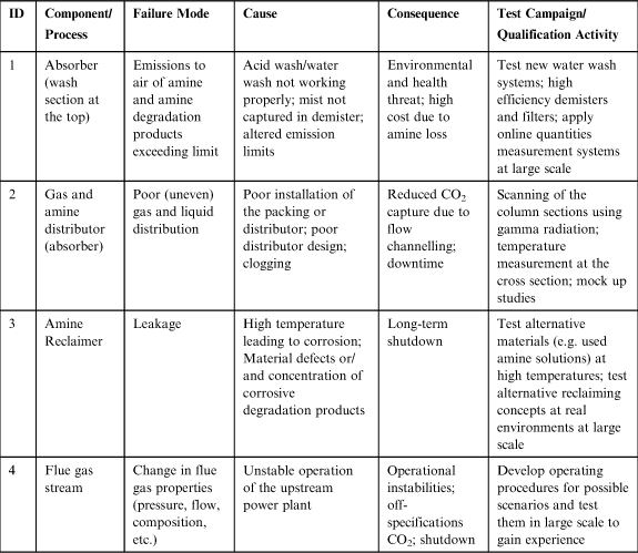
For a commercial scale absorption column to obtain the required performance, it is crucial that the gas and liquid distribution is uniform. The probability of challenges associated with uneven flow distribution increases with an increase in the column diameter. Both uneven liquid distribution and flue gas bypass contribute to loss of performance (Johnsen et al., 2009). A considerable loss of packing efficiency (due to, for instance, insufficient wetting of the packing) could be expected as a result of a small deviation in liquid distribution and liquid loading. This implies that packing type, gas–liquid distributor qualities and their installation methods have to be matched to those commercially practiced (Zhang et al., 2011). One way to evaluate the uncertainties with respect to liquid flow maldistribution at large scale is to accurately measure the temperature profile (as an indication of reaction rates) along the column height. This has been done at TCM’s amine unit through installation of 60 sensors in the absorber design (Andersson et al., 2012). Clear temperature profiles both horizontally and vertically in three different absorber zones indicated that proper liquid distribution was achieved throughout the column. The same conclusion was made through scanning of column internals using gamma radiation and after observing no abnormalities in the scans.
Reclaiming as an effective solution is necessary to avoid gradual build up to above allowed limits of impurities such as heat stable salts (HSS) formed in amine plants. Their accumulation would otherwise lead to excessive corrosion, foaming and capacity reduction. At TCM, a thermal reclaimer will be used to gather performance data and operational experience, which is scarce for reclaiming (De Koeijer et al., 2011). Depending on the amine type, operating conditions as well as flue gas specification, performance of different reclaiming technologies (e.g. high-pressure reclaimers) might be tested to evaluate the suitability for the desired application.
Increasing the size of the plant and the key equipment (such as the absorber column) requires new considerations and implications in design and operation phases. Doosan Babcock (2010) discussed uncertainties and probable challenges associated with corrosion when scaling up for CCS applications. A step change in the gas flow rate (typically from 10,000 to 20,000 tonnes/day for HP gas to 60000 tonnes/day for flue gas) might lead to mechanisms such as erosion–corrosion in the high flow areas as well as stress cracking corrosion to occur. Failures such as the latter are difficult to predict and they are most likely to happen unexpectedly. On the other hand, such large structures add logistic challenges. Precise process control may be difficult to apply due to large structures and more aggressive environments. Moreover, increased quantity of pipework to monitor will increase the risk of fouling in different locations and also make it difficult for corrosion to be traced to its source. Doosan Babcock (2010) suggests different solutions to the above-mentioned challenges such as use of corrosion-resistant alloys and anti-corrosion coatings and discuss pros and cons of each including economic viability.
A major scale-up challenge for today’s amine absorption technology is high cost to which high energy penalty is significantly contributing. A big share of the energy penalty originates from the high reboiler duty used for stripping the CO2 from the rich amine solvent. Developing specific guidelines as to how the scale-up, testing and validation of specific reboiler duty for an application have to be performed remains to be further investigated. Utilising previous similar experience coupled with process modelling is a key to success. It is also crucial to experimentally measure these energy demands. For instance the measured specific reboiler duty (MJ/kg of CO2 captured) for demonstration scale can be used to validate the calculated values. This approach can be even more useful for new solvents where there is a lack of reliable physical properties since it helps to increase the confidence in the model to be used for column dimensioning and design purposes. Andersson et al. (2012) reported initial measurements of specific energy consumption for TCM’s amine plant to vary between 4.1 and 5.0 MJ/kg CO2. They explain that the results are within the expected range for MEA for these operational conditions, based on earlier experiences.
A common challenge associated with amine solvents is solvent degradation which might have economic as well as health and environmental consequences. Any impurity entering the system, for instance from the upstream power plant through the flue gas stream, can initiate or accelerate degradation. The degradation products may consist primarily of different HSS such as formate, acetate and oxalate, carboxylate anions due to reactions between amines with O2 and SOx in the amine loop. The ideal situation for the plant is to have known and controlled degradation rates, mechanisms (oxidative or thermal) and products. Depending on the type of impurities, different tests and measurements can be performed to control and avoid uncontrolled degradation. One example is removing NO2 in the flue gas by using a sodium hydroxide solution in the direct contact cooler before the flue gas is fed to the absorber. However, careful control over reaction conditions such as optimal pH values have to be made ensuring the desired conditions is established. Online NO2 measurement and detection systems should be applied to ensure sufficient removal efficiency. Similar types of qualification activities at real plant conditions may be relevant for other possible impurities such as NH3 or ash depending on the type of fuel (coal, natural gas) and associated impurities in the power plant.
As mentioned in the sections above, a TQP can be developed during all stages of process development in order to highlight risk-prone aspects of the technology. The prerequisites are that a sufficiently detailed description of the final scale design exists to allow for a decomposition of the technology in order to understand the uncertainties and novelties of the system. This will help the vendor to avoid potential costly mistakes in the data collection that should otherwise be dealt with in later stages of development. A few typical examples for early stages of development are discussed below.
Possible size-dependency of the data obtained at smaller scales and their applicability for scale-up is a crucial aspect to evaluate during process development. One example is solvent screening which is usually performed in laboratory scale in order to select the preferred solvent through measuring kinetics, mass transfer coefficients and VLE data for the system. This is a task with a high number of experiments performed in various types of equipment. Characterisation (calibration) of the various apparatuses is a key issue and a potential source of uncertainty for the measured values. Moreover, when scaling up, the overall mass transfer coefficients obtained at small scale can normally not be directly used due to different hydrodynamic conditions at laboratory scale compared to the actual packed bed (e.g. gas inlet conditions) which could result in an overestimated coefficient (Zhang et al., 2011).
Another example of a challenge in scale-up is the scalability of the pilot plant’s operational mode and its relevance to the large-scale design and operation. Depending on how close the rich amine or acid gas stream compositions are to equilibrium, the pilot plant can be operated in different modes. These include rich end pinch (REP), lean end pinch (LEP) modes where equilibrium pinches occur either at the rich or lean end of the absorber, and the unpinched (UP) mode in which no close pinch occurs in the packing. In addition, the packed height and liquid flow rate should be within a certain range to ensure the requirements for each mode to occur. At LEP and REP modes the pilot plant is operated at one of the extremes, where the driving forces at the pinched ends cannot be accurately measured and where the column performance cannot be properly evaluated because the packing height is too large. The data obtained in these modes hence cannot be used for an accurate estimation of the effectiveness of mass transfer and height of packing required. It is only in the UP mode that a reliable mass transfer pilot data can be obtained. However, since the UP mode does not normally represent real large-scale operating conditions, where a close equilibrium approach is desired, the data obtained need to be fully understood before they are used for sizing the packing height for an industrial unit (Astarita et al., 1983). The analysis of UP mode pilot plant data should be based on an integrated method covering all physical, chemical and thermodynamic parameters involved with known assumptions to be justified. A complete check of both thermodynamic and rate models has to be done before sizing of an industrial unit can be done with confidence.
8.5 TQ and Process Development (Scale-Up) Stages
In some occasions it might be of benefit for stakeholders to provide a simple quantitative measure for the development state (i.e. maturity) of the technology. In order to express the development state of a technology, the risk-based scale-up approach described above might be used together with scales that give a measure for technology maturity. In Figure 8.3 an illustration is given of how qualification progresses through stages of development, represented here as milestones MS1, …, MS6. A ‘technology development state’ could be developed as such milestones or in parallel with milestones. As previously mentioned, maturity is closely related to uncertainty in the design and performance predictions of the final scale. Figure 8.3 illustrates that uncertainty and the probability of failure are reduced as qualification progresses, until a remaining failure probability is determined. Various measures could be used to demonstrate the achievement of a milestone as part of qualifying a technology for large-scale performance. The milestones could be related to process development stages and/or decision gates in project development. Then, one could represent uncertainty and risk at each stage which might be used in the decision-making. For instance, at each level in the process development, that is the various levels of scale, evaluate the probability that the technology will meet the pre-defined goals (requirements) required for the plant to be commercially successful, such as CO2 capture rate, energy consumption, amine emission levels, amine degradation, waste created, CO2 stream specifications, plant availability, etc. If the probability is above acceptable levels (quantitatively determined) for all goals, then this gives support for decision (or provides recommendation) to proceed to the next scale.

Figure 8.3 Illustration of qualification progress for development stages represented by a series of milestones (DNV, 2011).
A well-known scale used in industry is the TRL. TRLs indicate the degree of development of a technology and are normally used to communicate the maturity status at high level. The milestones shown in Figure 8.3 could be TRLs, where specific requirements are given for each level. This could be done as an integral part of the scale-up approach described above in several ways. For instance by developing a test campaign for each TRL or a test campaign for the full scale-up, but showing what tests are needed for each TRL. Currently, existence of several TRL scales makes it difficult for technology developers to communicate the status of their technology. Moreover, existing methods have limitations as to how different technologies can be compared on a fair basis. Given the considerable research and development efforts being made in development of CCS, a common platform for unbiased maturity assessment of various CO2 capture technologies could be developed by combining a risk-based qualification approach with generic TRL scales tailor-made for CO2 capture technologies. A more detailed discussion on combining TQ and TRLs are given by Bakhtiary-Davijany and Myhrvold (2012).
8.6 Summary
Mitigation of climate change has been a driver for developing technological solutions including CCS over the last few decades. Existence of a large number of projects focusing on development of PCC capture technologies calls for consecutive scale-up, validation and verification work for the commercialisation of large-scale industrial processes.
This work presents a risk-based qualification method for amine-based CO2 absorption processes for large-scale CCS applications. The method is based on DNV’s TQ procedures which aim at reducing the challenges posed by the uncertainties that reside in the design and performance predictions of new technologies at commercial scale. This work specifically applies the generic TQ method tailoring it for ‘scale-up’ of amine absorption processes for CCS application. An overview of the amine absorption technology and status of commercialisation is given. Different scale-up methods for well-defined and new technologies as well as industry’s traditional approach to scale up of amine absorption processes for CCS are reviewed and discussed. Main challenges for the scale-up are high cost, complexity and size-dependency of the multiple phenomena involved as well as unavailability of relevant scale-up experience on the specific field of interest. The method is described as a tool for managing scale-up risks in a systematic and cost-efficient way by identifying the adequate tests for the specific process.
A case study demonstrating examples of industrial scale-up challenges and tests required to tackle them is given based on publically available literature. Among these challenges are emission of amines and their degradation products to air, amine degradation, maldistribution of flow in the absorber, corrosion and high energy consumption. Within the framework of a TQP the examples of tests and other qualification activities to reduce the associated risk to an acceptable level are discussed. Also a few examples of challenges for lower maturity levels such as laboratory and pilot plant scale are discussed and crucial aspects connected to scalability of the collected data and their use for design of a large-scale plant is highlighted.
Finally, the possibility of using TQ, when coupled with TRL, as a quantitative measure for the development state (i.e. maturity) of the technology during process development is discussed.
References
1. Aaron D, Tsouris C. Separation of CO2 from flue gas: a review. Sep Sci Technol. 2005;40:321–348.
2. Andersson, V., Wittmeyer, K., Gorset, O., Maree, Y., Sanden, K., 2012. Operational experience and initial results from the first test period at CO2 Technology Centre Mongstad, Presented at GHGT-11. International Conference on Greenhouse Gas Technologies, Kyoto, Japan.
3. Aspen Plus. Aspen Plus One Version V7 Cambridge, MA: Aspen Technology Inc.; 2008.
4. Astarita G, Savage D, Bisio A. Gas Treating with Chemical Solvents New York, NY: John Wiley and Sons; 1983.
5. Bakhtiary-Davijany, H., Myhrvold, T., 2012. On methods for maturity assessment of CO2 capture technologies, Presented at GHGT-11. International Conference on Greenhouse Gas Technologies, Kyoto, Japan.
6. Billet R. Contribution to design and scale-up of packed columns. Fat Sci Technol. 1990;929:361–370.
7. Billet R. Contribution to packed column scale-up in separation process. J Chem Ind Eng. 1992;7(2):235–252.
8. Bisio A, Kabel RL. Scale-up of Chemical Processes, Conversion from Laboratory Scale Tests to Successful Commercial Size Design New York, NY: John Wiley and Sons; 1985.
9. De Koeijer G, Enge Y, Sanden K, et al. CO2 Technology Centre Mongstad – design, functionality and emissions of the amine plant. Energy Procedia. 2011;4:1207–1213.
10. Det Norske Veritas AS, 2010a. DNV-OSS-401. Technology Qualification Management, Høvik, Norway.
11. Det Norske Veritas AS, 2010b. DNV-RP-J201. Qualification Procedures for CO2 Capture Technology, Høvik, Norway.
12. Det Norske Veritas AS, 2011. DNV-RP-A203. Qualification of New Technology. Høvik, Norway.
13. Dimian AC, Bildea CS, Kiss AA. Integrated Design and Simulation of Chemical Processes Amsterdam: Elsevier; 2003.
14. Donati G, Paludetto R. Scale-up of chemical reactors. Catal Today. 1997;34:483–533.
15. Doosan Babcock, 2010. Scale up of amine scrubbing for carbon capture: implications for corrosion preventive strategies. Presented at Opportunities in Carbon Capture and Storage, Harrogate, UK.
16. Folger, P., 2010. Carbon Capture: A Technology Assessment. Congressional Research Service Reports. Paper 19. Online Cited, February 28, 2013.
17. Gjernes, E., Helgesen, L.I., Maree, Y., 2012. Health and environmental impact of amine based post combustion CO2 capture. Presented at GHGT-11. International Conference on Greenhouse Gas Technologies, Kyoto, Japan.
18. Global CCS Institute, 2012. The Global Status of CCS, 2012 report. Canberra, Australia, ISBN: 978-0-9871863-1-7.
19. Green DW, Perry RH. Perry’s Chemical Engineers’ Handbook eighth ed. The McGraw-Hill Companies 2007; ISBN: 0071422943.
20. Hessen, E.T., Bakhtiary-Davijany, H., Myhrvold, T., 2012. Process modelling in risk-based qualification of large-scale CO2 absorption processes. Presented at GHGT-11. International Conference on Greenhouse Gas Technologies, Kyoto, Japan.
21. Johnsen K, Helle K, Myhrvold T. Scale-up of CO2 capture processes: the role of technology qualification. Energy Procedia. 2009;1(1):163–170.
22. Myhrvold T, Helle K, Johnsen K, Hussain A. Development of a guideline for the qualification of CO2 capture technology. Energy Procedia. 2009;1(1):1527–1534.
23. Oyenekan BA, Rochelle GT. Energy performance of stripper configurations for CO2 capture by aqueous amines. Ind Eng Chem Res. 2006;45:2457–2464.
24. Razi N, Bolland O, Svendsen H. Review of design correlations for CO2 absorption into MEA using structured packings. Int J Greenhouse Gas Control. 2012;9:193–219.
25. Sinnott R, Towler G. Coulson and Richardson’s chemical engineering series. Chem Eng Des. 2009.
26. SINTEF, 2012. CO2SIM, Flowsheet Simulator for CO2 Absorption Processes. <www.sintef.no> (accessed 18.3.2013).
27. Tatterson, G.B., 2002. Process Scale-up and Design, ISBN: 0-9726635-0-9.
28. Tobiesen, F.A., 2006. Modelling and Experimental Study of Carbon Dioxide Absorption and Desorption, PhD thesis, Norwegian University of Science and Technology (NTNU).
29. Waters PL. Strategy for the development of chemical processes. Proc Roy Aust Chem Inst. 1973;40(7):183–191.
30. ZEP, 2006. The European Technology Platform for Zero Emission Fossil Fuel Power Plants, The Final Report from Working Group 1 – Power Plant and Carbon Dioxide Capture.
31. Zhang R, Purusha Bonnin-Nartker E, Farthing GA, et al. RSAT™ process development for post-combustion CO2 capture: scale-up from laboratory and pilot test data to commercial process design. Energy Procedia. 2011;4:1660–1667.