


IBM SmartCloud Entry usage
This chapter covers usage of the cloud system that is configured in the previous chapter. Two main topics are covered for both the Power nodes and x86 nodes.
•How to deploy appliances. These actions allow users to create workload based on the appliances create by the administrators.
•How to capture deployed workloads into new appliances. This allows users to back up their active workloads. It also provides administrators a standard interface for creating appliances for both platforms.
6.1 Deploying appliances
This section tells how to deploy appliances on POWER and x86 to create workloads.
6.1.1 Deploying a Power appliance
The discovered appliances that IBM SmartCloud Entry lists are ready to deploy. However, in the following example, the appliance must be slightly modified because the networking configuration that IBM SmartCloud Entry will use for the appliance as it is deployed might not be correct. Recall in 4.3, “Networking setup” on page 27 that there is a complex network inside the IBM Flex Chassis. Also, recall that two VLANs are used (4091 and 1).
In 5.3, “Configuring cloud network pools” on page 151, two network pools were created to correspond to the two VLANs.
Again, log in to the user interface. In the main panel, select the Appliances tab. Several appliances are listed (Figure 6-1).

Figure 6-1 List of appliances ready to be deployed
Select the AIX71_appliance link. This appliance corresponds to the AIX image that was created in 4.6.4, “Install AIX” on page 77. Click Configure (Figure 6-2).

Figure 6-2 An appliance is selected to be configured
The configuring appliance panel opens. For ease of reading, this panel is spread across several figures (Figure 6-3 through Figure 6-6 on page 184).
Figure 6-3 shows the overall settings of the appliance. It includes shared virtual processors.

Figure 6-3 Overall settings of the appliance
Scroll down to see the network settings (Figure 6-4). This information is pre-populated from the information set in 5.3, “Configuring cloud network pools” on page 151.

Figure 6-4 Network settings of the appliance
The first of the two adapters is shown in Figure 6-5. It is important to select the correct Network ID for this adapter. These adapters represent the setup configured in 4.3.1, “Chassis and compute node setup” on page 27. In Figure 6-5, the Network ID for VLAN 4091 is selected.

Figure 6-5 Adapter Specifications
Figure 6-6 shows the second adapter. This is the adapter for VLAN 1.

Figure 6-6 Second adapter specification
Save the appliance. You may then deploy it by clicking Deploy. Set a name for this deployment (Figure 6-7).

Figure 6-7 Providing a name for the deployment
The request for the deployment is sent as a new workload (Figure 6-8). The new workload has the same settings as configured in the previous step.

Figure 6-8 Request for deployment sent as a new workload
The Workloads tab shows the workload as being deployed (Figure 6-9).

Figure 6-9 Workloads Status
When the workload is finished, an email notifies (Figure 6-10) the appropriate user that the workload was deployed. This email also contains the information to log in to the newly created operating system.

Figure 6-10 Workload completed email
Using the information provided in the email shown in Figure 6-10 on page 186, the user requesting the workload can log in, as shown in Example 6-1.
Example 6-1 Logging in
#:~$ ssh [email protected]
The authenticity of host '129.40.21.198 (129.40.21.198)' can't be established.
RSA key fingerprint is 12:b3:0b:2c:2e:4c:38:ba:48:10:4c:4b:5b:41:97:4c.
Are you sure you want to continue connecting (yes/no)? yes
Warning: Permanently added '129.40.21.198' (RSA) to the list of known hosts.
[email protected]'s password:
X11 forwarding request failed on channel 0
Last login: Tue Nov 27 18:43:01 CDT 2012 on ssh from f3enfsm.pbm.ihost.com
***************************************************************************
* *
* *
* Welcome to AIX Version 7.1! *
* *
* *
* Please see the README file in /usr/lpp/bos for information pertinent to *
* this release of the AIX Operating System. *
* *
* *
***************************************************************************
# ifconfig -a
en0: flags=1e080863,480<UP,BROADCAST,NOTRAILERS,RUNNING,SIMPLEX,MULTICAST,GROUPRT,64BIT,CHECKSUM_OFFLOAD(ACTIVE),CHAIN>
inet 129.40.21.198 netmask 0xffffffe0 broadcast 129.40.21.223
tcp_sendspace 262144 tcp_recvspace 262144 rfc1323 1
en1: flags=1e080863,480<UP,BROADCAST,NOTRAILERS,RUNNING,SIMPLEX,MULTICAST,GROUPRT,64BIT,CHECKSUM_OFFLOAD(ACTIVE),CHAIN>
inet 192.168.1.5 netmask 0xffffff00 broadcast 192.168.1.255
tcp_sendspace 262144 tcp_recvspace 262144 rfc1323 1
lo0: flags=e08084b,c0<UP,BROADCAST,LOOPBACK,RUNNING,SIMPLEX,MULTICAST,GROUPRT,64BIT,LARGESEND,CHAIN>
inet 127.0.0.1 netmask 0xff000000 broadcast 127.255.255.255
inet6 ::1%1/0
tcp_sendspace 131072 tcp_recvspace 131072 rfc1323 1
#
6.1.2 Deploying an x86 appliance
VMware appliances must be configured in a similar manner as in the previous section. The first panel differs slightly from that section to show that VMware requires different information to successfully be deployed (Figure 6-11).

Figure 6-11 Configuration using VMware
The network setup is not as complex, because the VMware switch on the ESXi already defines the network ID.
Click Save. The appliance is saved (Figure 6-12).

Figure 6-12 Saved appliance
The saved appliance can be deployed (Figure 6-13).

Figure 6-13 Deployment snapshot
A notification is sent for the x86 appliance (Figure 6-14).

Figure 6-14 Deployment snapshot has been sent for deployment as workload
6.2 Capturing a workload
In this section, workloads are captured on POWER and on x86.
6.2.1 Capturing a Power workload
Capturing a Power workload in SmartCloud Entry is nearly identical to capturing a workload in VMControl on the FSM (covered in 4.6.7, “Capture virtual server” on page 89). The first step is to shut down the workload so that it is eligible for capture (Figure 6-15).

Figure 6-15 Shut down workload so it is eligible for capture
SmartCloud Entry sets an on-screen notification that the workload has been stopped. Click Capture. Figure 6-16 shows the notification as the request is sent to the cloud.

Figure 6-16 Workload has been stopped
An email is sent to the requesting user when the capture is completed (Figure 6-17).

Figure 6-17 Confirmation email that deployment has completed successfully
The IBM SmartCloud Entry Appliances tab is updated with the new appliance (Figure 6-18).
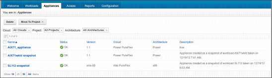
Figure 6-18 Appliance tab is updated with new appliance information and status
6.2.2 Capturing an x86 Workload
To capture an x86 workload, its status must appear as stopped (Figure 6-19).

Figure 6-19 On screen notification that a workload has stopped
IBM SmartCloud Entry issues an on-screen notification that the workload was stopped. Now you can click Capture. A notification that is displayed (Figure 6-20) as the request is sent to the cloud as a result. An information icon is displayed in the upper left of window.

Figure 6-20 Information icon and message: Capture request has been sent
An email is sent to the requesting user when the capture is completed (Figure 6-21).

Figure 6-21 An email notification: capture of deployment has completed successfully
The IBM SmartCloud Entry Appliances tab is updated with the new appliance (Figure 6-22).

Figure 6-22 Appliance tab is updated with new appliance information
..................Content has been hidden....................
You can't read the all page of ebook, please click here login for view all page.