

IBM TS4300 tape library
The latest library from IBM, the IBM TS4300 tape library (Model 3555), is a highly expandable IBM Ultrium library that supports LTO 8, 7, and 6 drives. Starting with one 3U base module (Model L3A), you can add up to six expansion modules (Model E3A) in the same rack, giving a maximum capacity of 272 LTO cartridges, and up to 3.2 PB of data storage. The TS4300 base module can also be used as a table top library, as long as no further capacity expansion is required.
The base unit of the TS4300 tape library can accommodate either up to three Ultrium half-high tape drives, one Ultrium full-high, or a combination of one Ultrium full-high plus one Ultrium half high tape drive. SAS and Fibre Channel drives can both be installed. It can also hold up to 40 data cartridge slots in two removable magazines, including a standard five-cartridge I/O station. Other standard features include a 240 x 128 Monochrome control panel with a front USB port, a 10/100/1000 Ethernet Port, and a high-speed bar code reader.
On its maximum configuration of one base unit and six expansions, the TS4300 tape library can accommodate up to 21 Ultrium half-high tape drives, seven Ultrium full-high tape drives, or a combination of both based on the drive form factor. The space needed for one full-height drive equals two half-height drives.
This chapter includes the following topics:
12.1 Product description
The IBM TS4300 tape library is a modular, vertically scalable library design offering with the following features and support:
•A 3-U rack-mounted L3A base module that provides up to three Half-High IBM Ultrium LTO-8, 7, or 6, or one Full-High and one Half-High Ultrium LTO-8, 7, or 6 tape drives, up to 40 storage slots, and up to five I/O slots.
•Installation of up to six 3-U E3A expansion modules in each library, each of which provides three Half-High IBM Ultrium LTO-8, 7, or 6, or one Full-High and one Half-High Ultrium LTO-8, 7, or 6 tape drives, up to 40 storage slots, up to five of which you can optionally configure as I/O slots.
•IBM Ultrium 8 tape drive support for 8 Gbps Fibre Channel or 6 Gbps SAS tape drives, which can be mixed in the physical library.
•IBM Ultrium 7 tape drive support for 8 Gbps Fibre Channel or 6 Gbps SAS tape drives, which can be mixed in the physical library.
•IBM Ultrium 6 tape drive support for 8 Gbps Fibre Channel or 6 Gbps SAS tape drives, which can be mixed in the physical library.
•Support for remote management through a web interface. Local management is done through a black and white Operator Control Panel and buttons.
•Data security and regulatory compliance through support for library-managed encryption (LME) and WORM media on LTO Ultrium 8, 7, and 6 tape drives.
•IBM patented multi-path architecture with logical library support to share the library between multiple homogeneous or heterogeneous systems or applications.
•Supports media partitioning and self-describing tape with IBM Spectrum Archive Library Edition (LE) and Enterprise Edition (EE) enabling Linear Tape File System (LTFS) software.
•Supports the use of Key Management Interoperability Protocol (KMIP) on key management servers, including sKLM for z/OS Encryption (IBM IPP).
•Support for a wide range of systems including IBM Power Systems (p6 and newer), IBM System p (p5 and earlier), pSeries, System x, xSeries, System i, iSeries, Intel, and Oracle.
•A bar code reader.
•Support of Sequential mode logical library configuration.
|
Note: Ultrium 5 and earlier drives are not supported in the TS4300 library.
|
Optionally, you can install the following features:
•Path failover for control paths and data paths
•LTO Lib Managed Encryption
•Redundant power supplies for each module
•Rack mounting kit
A fully expanded TS4300 tape library today occupies 21U of rack space and a potential maximum of 272 storage slots with the following storage:
•3.8 PB of storage on Ultrium 8 media at native capacity (8.16 PB at a 2.5:1 compression ratio)
•1632 TB of storage on Ultrium 7 media at native capacity (4.08 PB at a 2.5:1 compression ratio)
•680 TB of storage on Ultrium 6 media at native capacity (1.7 PB at a 2.5:1 compression ratio)
All configurations require one TS4300 tape library Model L3A base module. Expansion is provided through the addition of the TS4300 tape library Model E3A expansion modules.
The TS4300 tape library supports all the following encryption methods:
•Application-managed encryption is available at no charge
•Library-managed encryption by using FC 9500
12.1.1 TS4300 tape library Model L3A (Machine Type 3555)
The base module (as shown in Figure 12-1) offers the following standard features:
•A library control module with a remote management interface.
•Up to 40 storage slots per module. Only 32 slots are available on the only (base) module or the lowest rack-installed module in the TS4300 library.
•Up to five I/O slots, configurable as storage slots if the library is expanded or if an I/O station is not required. Only four slots will be available for the I/O station if this is the only (base) module or the lowest rack-installed module in the TS4300 library.
•A black and white Operator Control Panel for local management.
•Cartridge handling robotics and bar code reader.
•Support for logical libraries.
•Up to three Ultrium 8, 7, or 6 Half-High tape drives, or one Full-High and one Half-High Ultrium 8, 7, or 6 tape drives.
•A power supply unit (PSU). A second PSU is optionally available for redundancy.
•Enablement of path failover for control paths and data paths through a chargeable license.
The TS4300 L3A base module front view is shown in Figure 12-1.

Figure 12-1 Front view of TS4300 L3A base module
12.1.2 TS4300 tape library Model E3A (Machine Type 3555)
The expansion module (as shown in Figure 11-2) offers the following features:
•Up to 40 storage slots per module. Only 32 slots are available on the only (base) module or the lowest rack-installed module in the TS4300 library.
•Up to five I/O slots, configurable as storage slots if the library is expanded or if an I/O station is not required. Only four slots are available for the I/O station if this is the lowest rack-installed expansion module in the TS4300 library.
•Up to three Ultrium 8, 7, or 6 Half-High tape drives, or one Full-High and one Half-High Ultrium 8, 7, or 6 tape drive.
•A PSU. A second optional PSU is available for redundancy.
The TS4300 E3A expansion module front view is shown in Figure 12-2.

Figure 12-2 Front view of TS4300 E3A expansion module
12.2 Library expansion
As described earlier in this chapter, the base library can be easily scaled up with the addition of expansion modules. The TS4300 tape library uses a single robust flow-through design robotic system to access all drives and media. The design does not use complex pass-through ports or elevator systems, which removes the need for expensive duplication of robotics and control electronics with each library expansion. It also results in more reliable library operations.
Expansion modules can be installed above or below the base module. This process takes approximately an hour to complete. When multiple expansion modules are used, they can be installed around the base module, if preferred. However, keep the base module at a convenient access height for access to the control panel. A full TS4300 library consists of three expansion modules on the top, then a base module, and three expansion modules on the bottom. I/O station slots can be configured in both base and expansion modules, depending on your preference.
|
Note: I/O station slots and drives are dedicated to logical libraries and are not shared. It is important to consider this factor when planning logical libraries for the TS4300.
|
For more information about the preferred library configuration setup, see IBM TS4300 Tape Library Machine Type 3555 Users Guide, SC27-4629.
|
Tip: Consider leaving a minimum clearance of 6 inches above the library for Service Clearance.
|
Figure 12-3 shows the TS4300 expansion path. The addition of each expansion module provides another 40 storage slots, unless it is the lowest module for the library installed in the rack; then, only 32 slots are available.

Figure 12-3 TS4300 tape library expansion path
You can configure the I/O slots in each module to operate as I/O slots or storage slots. This method provides a high degree of flexibility. For example, in a library configuration of one L3A base unit and one E3A expansion unit, the following combinations are possible:
•No I/O slots (slots will become available for storage slots)
•A total of 4 I/O slots (all in the base module)
•A total of 9 I/O slots (that use the slots in the base module and the expansion module)
Expansion of the TS4300 tape library is granular and highly configurable. Table 12-1 lists the configuration options that are available as the base module expands. The cartridge accessor mechanism cannot access the bottom row of cartridge slots in the library.
Table 12-1 TS4300 tape library configuration
|
Library configuration
|
Number of available I/O station slots
|
Number of accessible storage slots
|
Total slots
|
|
3U library (base module only)
|
0, 4
|
32, 28
|
32
|
|
6U library (base module and expansion)
|
0, 4, 9
|
72, 68, 63
|
72
|
|
9U library (base library and two expansions)
|
0, 4, 9, 14
|
112, 108, 103, 98
|
112
|
|
12U library (base library and three expansions)
|
0, 4, 9, 14, 19
|
152, 148, 143, 138, 133
|
152
|
|
15U library (base library and four expansions)
|
0, 4, 9, 14, 19, 24
|
192, 188, 183, 178, 173, 168
|
192
|
|
18U library (base library and five expansions)
|
0, 4, 9, 14, 19, 24, 29
|
232, 228, 223, 218, 213, 208, 203
|
232
|
|
21U library (base library and six expansions)
|
0, 4, 9, 14, 19, 24, 29, 34
|
272, 268, 263, 258, 253, 248, 243, 238
|
272
|
|
Note: It is possible to disable all I/O stations in the TS4300, and use all the I/O slots as storage slots. In this case, a bulk cartridge load of the library is required, and any subsequent imports/exports of cartridges cause the library to be taken offline during the process.
|
12.3 Front panel components
Figure 12-4 shows the front view of a TS4300 tape library with a base module and expansion module on top. The access door (top cover) is on the top of the library to allow access to the interior of the library. The expansion module is shown with its I/O station open, ready for the import of cartridges. The front panel of the base module contains the Operator Control Panel and associated buttons to the right, power button, and magazine buttons.

Figure 12-4 Front view of a TS4300 6U library configuration
12.3.1 I/O station and magazine
Figure 12-5 shows the right side I/O station and magazine door.

Figure 12-5 I/O door and Magazine
I/O stations are on the right side of the front panel of the library to enable the inserting and removing of cartridges without interrupting normal library operations. An expansion module’s I/O station has a capacity of up to five cartridges, depending on where it is located. If it is the lowest module in the rack for the library, it has only four I/O slots available.
Individual I/O station elements cannot be shared between logical libraries. Importing or exporting cartridges in a logical library without an assigned I/O station requires magazine access, which takes the whole library offline.
When an operator places cartridges in the I/O station and closes it, the library scans the slots to update the library inventory. Cartridges should then be moved to storage slot locations by using the Web User Interface (Web UI) or your backup application. Using the Web UI, cartridges can be moved from one logical library’s I/O station slot to a storage slot in another logical library. However, a warning alert box is shown and the action must be confirmed.
To unlock the I/O station, click Library → Modules and Magazines → Actions → Unlock I/O Station from the management interface. The station can then be opened by pulling on the magazine access handle. The magazine I/O button LED will indicate status of the I/O and magazine, as shown in Table 12-2.
Table 12-2 Magazine state
|
Magazine state
|
LED state
|
Description
|
|
Closed
|
Steady ON
|
I/O station is enabled
|
|
Closed
|
Slow Flash
|
Magazine open is in process
|
|
Closed
|
Fast Flash
|
Magazine is opened
|
|
Closed
|
OFF
|
I/O station is not enabled
|
|
Opened
|
OFF
|
Magazine is opened
|
|
Note: Using the management interface to open the I/O station times out after 30 seconds. To manually open the I/O station after timeout, press the magazine button for less than 3 seconds and then open using the handle. To open the entire magazine, press the magazine button for more than 3 seconds.
|
As explained in 11.9, “Working with logical libraries” on page 304, careful planning for logical libraries, including I/O station elements and cartridge drives, should be performed before configuration of the library occurs. Consideration should be given to media import and export operations during this planning phase.
12.3.2 Access door
Each TS4300 base module and expansion module has a top cover that allows access to the internal components of the library. This top cover is released by using two screwdrivers to depress small button clips near the front of the cover.
When the top cover is removed, all in-progress motion commands stop and the library is taken offline. When the top cover is replaced, the library returns any media in the accessor to its original storage slot.
|
Attention: Do not override the top cover switch because this action might result in accessor mechanism damage.
|
12.3.3 Operator control panel
The Operator Control Panel (OCP) consists of a black and white display and buttons on the front of the base module. Library operations, configuration, and service functions are performed from this display and its associated buttons.
The OCP has a power button, an LCD display, six navigation buttons, and five LEDs. With the OCP, you can monitor, configure, and operate most library functions from the library front panel. To use the OCP, use the six navigation buttons (up/down, left/right, Enter, Back).
The Web UI offers part of the same functionality as the operator window from a web browser, which enables remote access to the library. For more information about the operator panel and the web UI, see 12.7, “Library management” on page 326.
12.3.4 Power button
Pressing the power button on the front panel of a control module turns the library on or off. However, with the power button in the off position, power is still applied to the power supplies. The power button is used during library shutdown and to manually restart the library.
12.3.5 Front panel LEDs
Figure 12-6 on page 319 shows the row of LEDs on the front of the library to the right of the power button:
•Green: Ready LED. Steady when power is on, flashing with tape Ready drive or library robotic activity.
•Blue: Unit ID LED. The unit identification (UID) LEDs are controlled by the user through the OCP Maintenance → UID LED control panel.
The UIDs on the OCP and base module back panel are activated and deactivated together. In addition, UIDs on drives and expansion module back panels can be activated separately. The UIDs are helpful for locating components of the library in a Data Center.
•Amber: Clean LED. On when a tape drive clean operation is recommended.
•Amber: Attention LED. Flashing if the library has detected a condition for which user attention is necessary, but the library can still complete most operations.
•Amber: Error LED. On, if an unrecoverable tape drive or library error occurs. A corresponding error message is displayed on the LCD panel. User intervention is required because the library is not capable of completing some operations.

Figure 12-6 Front panel LEDs
12.4 Rear panel components
Figure 12-7 shows the rear view of a 6U (one base module and one expansion module) TS4300 library and its major components. On the right side of the library, you can see the expansion cable which connects the base module library controller to the expansion module. Subsequent expansion modules are also “daisy-chained” together in this way.

Figure 12-7 Rear panel view of 6U library
12.4.1 Library Controller
The Library Controller manages the entire library, including the operator panel and accessor. It is responsible for running system tests to ensure that the library functions properly. The Library Controller stores vital product data (VPD), such as library settings and the library serial number.
The Library Controller indicates status with three vertically positioned LEDs. The color of the LED identifies the area of the component that is reported. They are, from top to bottom, as follows:
•Green: Ready LED. Library in Ready Status and operating properly
•Amber: Error LED. Library in Error Status and the controller has a hardware issue
•Blue: Unit ID LED. The UID LEDs are controlled by the user through the maintenance panel. The UIDs are helpful for locating components of the library in a Data Center
12.4.2 Tape drives
The TS4300 library supports Half-High SAS and Fibre Channel, and Fibre Channel Full-High, Ultrium 8, 7, and 6 drives. Ultrium 5 and earlier drives are not supported in the TS4300. Tape drives are hot-addable, which mean the library power remains on and operations of the existing tape drives are still active. Drives can be removed and installed without tools. The drive sleds are customer-replaceable units (CRU).
Drives are mounted in sleds that are installed into tape drive slots in the rear of the library. If a tape drive slot is empty, a metal plate covers the empty drive slots to prevent any debris from entering the library.
|
Important: If you install Full-High Fibre Channel drives in the TS4300, they must be in the lowest drive position. In this case, another Half-High drive can be installed above it, if wanted.
|
TS4300 tape library Ultrium 8 models
The following models are available for the TS3200 tape library:
•The 3555-L3A feature AGKP specifies an IBM Ultrium 8 Full-High Fibre Channel tape drive. The Ultrium 8 Fibre Channel drive has an 8 Gbps Fibre Channel interface that can be connected to Fibre Channel host adapters. The Ultrium 8 tape drive has a native data transfer rate of 360 MBps.
•The 3555-L3A feature AGKN specifies an IBM Ultrium 8 Half-High tape drive that has an SAS interface and a native data transfer rate of up to 6 Gbps. The SAS Ultrium 8 tape drive comes with dual-port Mini-SAS (SFF-8088) interfaces. The Ultrium 8 tape drive provides a sustained native data transfer rate of 300 MBps.
•The 3555-L3A feature AGKM specifies an IBM Ultrium 8 Half-High Fibre Channel tape drive. The Ultrium 8 Fibre Channel drive has an 8 Gbps Fibre Channel interface that can be connected to Fibre Channel host adapters. The Ultrium 8 tape drive has a native data transfer rate of 300 MBps.
TS4300 tape library Ultrium 7 models
The following models are available for the TS3200 tape library:
•The 3555-L3A feature AGKL specifies an IBM Ultrium 7 Full-High Fibre Channel tape drive. The Ultrium 7 Fibre Channel drive has an 8 Gbps Fibre Channel interface that can be connected to Fibre Channel host adapters. The Ultrium 7 tape drive has a native data transfer rate of 300 MBps.
•The 3555-L3A feature AGKK specifies an IBM Ultrium 7 Half-High tape drive that has an SAS interface and a native data transfer rate of up to 6 Gbps. The SAS Ultrium 7 tape drive comes with dual-port Mini-SAS (SFF-8088) interfaces. The Ultrium 7 tape drive provides a sustained native data transfer rate of 300 MBps.
•The 3555-L3A feature AGKJ specifies an IBM Ultrium 7 Half-High Fibre Channel tape drive. The Ultrium 7 Fibre Channel drive has an 8 Gbps Fibre Channel interface that can be connected to Fibre Channel host adapters. The Ultrium 7 tape drive has a native data transfer rate of 300 MBps.
TS4300 tape library Ultrium 6 models
The following models are available for the TS3200 tape library:
•The 3555-L3A feature AGKH specifies an IBM Ultrium 6 Full-High Fibre Channel tape drive. The Ultrium 6 Fibre Channel drive has an 8 Gbps Fibre Channel interface that can be connected to Fibre Channel host adapters. The Ultrium 6 tape drive has a native data transfer rate of 160 MBps.
•The 3555-L3A feature AGKG specifies an IBM Ultrium 7 Half-High tape drive that has an SAS interface and a native data transfer rate of up to 6 Gbps. The SAS Ultrium 6 tape drive comes with dual-port Mini-SAS (SFF-8088) interfaces. The Ultrium 6 tape drive provides a sustained native data transfer rate of 160 MBps.
•The 3573-L4U feature AGKF specifies an IBM Ultrium 6 Half-High Fibre Channel tape drive. The Ultrium 6 Fibre Channel drive has an 8 Gbps Fibre Channel interface that can be connected to Fibre Channel host adapters. The Ultrium 6 tape drive has a native data transfer rate of 160 MBps.
Figure 12-8 shows the back of an LTO-8 Full-High FC tape drive, LTO-8 HH FC tape drive, and LTO-8 HH SAS drive.

Figure 12-8 Back side of the LTO-8 Full-High FC tape drive
|
Tip: When connecting, Fibre Channel tape drives are connected to a Fibre Channel host bus adapter (HBA) on the host server. Ensure that the Fibre Channel Tape Support option is enabled on the Fibre Channel HBA so that proper class 3 error recovery is performed on the Fibre Channel. For more information about how to set this option, see the HBA manufacturer instructions.
|
12.4.3 Power supply
The library supports single and redundant power configurations. Each TS4300 base or expansion module has an upper and lower power supply. A single power configuration has a power supply that is installed in the upper slot of each library module. A redundant power configuration has power supplies that are installed in both upper and lower slots of each library module.
When two power supplies are used in a single module, the power load is spread evenly over both power supplies. If one of the power supplies fails, the power load is drawn entirely from the functioning power supply.
The single configuration has a single AC line input and a single DC power supply. The optional redundant configuration has dual AC line input and dual DC power supplies. A power supply can be hot-swapped if the library has a redundant power supply, and a redundant power supply can be hot added.
|
Note: There are no power switches on the power supplies on the back of the modules. The library should be powered down by using the power button on the base module and following the prompts. Except in emergency situations, use the shutdown procedure before removing power to the modules.
|
The power system of the library contains the following components:
•Power Supply Unit
•An AC power cord
The power supply has two LEDs that provide status information. The LEDs, which are to the right of the power cord, are green and white and indicate the following conditions:
•White Upper LED: AC power is connected
•Green Lower LED: Module powered ON
12.5 Interior components
Storage columns and the robotic system are in the body of the library.
12.5.1 Storage columns
Storage columns within the library store the tape cartridges while they are not loaded in a drive.
Figure 12-9 shows an example of the TS4300 tape library storage columns in the base model. The library contains four storage columns and the I/O Station, when configured, is in the upper right corner of the photo. Drives are visible in the center left side of the photo.

Figure 12-9 TS4300 tape library storage columns
12.5.2 Robotic system
The TS4300 robotic system includes the Y-axis assembly that houses the Y motor, which is attached to the carrier, and the bar code scanner. The climber moves the robotic system within the library. The accessor (robotic arm) has finger-like mechanisms that it uses to grab tape cartridges and move them to and from the I/O station, storage slots, and drives.
The bar code scanner reads each cartridge bar code label and the fiducial labels that identify the types of cartridge magazines and tape drives that are installed in the library.
Figure 12-10 shows the robot accessor in the center of the photo, and the robotic lock lever for transportation at the right side. Also visible above and below the accessor are the magazines that contain storage slots, and on the upper right side are the I/O slots if configured.

Figure 12-10 TS4300 robotic accessor
12.6 Optional features
The TS4300 tape library is highly configurable and enhanced functionality is available through the provision of optional features.
12.6.1 IBM Ultrium tape drives
The TS4300 tape library allows the following tape drive options:
•UItrium LTO-8 6 Gbps SAS Half-High drive
•UItrium LTO-7 6 Gbps SAS Half-High drive
•UItrium LTO-6 6 Gbps SAS Half-High drive
•Ultrium LTO-8 8 Gbps Fibre Channel Half and Full High drives
•Ultrium LTO-7 8 Gbps Fibre Channel Half and Full High drives
•Ultrium LTO-6 8 Gbps Fibre Channel Half and Full High drives
UItrium LTO-5 technology and earlier drives are not supported in the TS4300 library.
For more information, see Chapter 2, “Overview of IBM LTO Ultrium tape drives” on page 45.
The IBM Ultrium tape drive contains the electronics and logic for reading and writing data, controlling the tape drive, managing the data buffer, and handling error recovery procedures. It is a CRU and can easily be replaced if necessary.
Table 12-3 shows a comparison of some features and characteristics of the UItrium LTO 8, 7, and 6 tape drives.
Table 12-3 Characteristics and features
|
Characteristics and features
|
Ultrium 8 tape drive
|
Ultrium 7 tape drive
|
Ultrium 6 tape drive
|
|
Native data rate
|
360 MBps (FC)
300 MBps (SAAS) (with Ultrium 8 media)
|
300 MBps (with Ultrium 7 media)
|
160 MBps (with Ultrium 6 media)
|
|
Cartridge compatibility
Ultrium and Ultrium WORM
|
LTO-8 read/write
LTO-7 read/write M8 format media
LTO-7 read/write
|
LTO-7 read/write
LTO-6 read/write
|
LTO-6 read/write
|
|
Cartridge capacity
native/compressed
|
12 TB/30 TB
9 TB/22.5 TB using M8 format media
|
60 TB/15 TB
|
2.5 TB/6.25 TB
|
|
Speed matching support
|
Yes
|
Yes
|
Yes
|
|
Channel calibration
|
Yes
|
Yes
|
Yes
|
|
Giant magneto-resistive head
|
No
|
Yes
|
Yes
|
|
Tunneling Magnetoresistive (TMR) head technology
|
Yes
|
No
|
No
|
12.6.2 Redundant power supply
The service representative can hot swap the optional redundant configuration power supplies (FC1900) without interrupting library operation. Each supply in a control module and expansion module includes its own input AC power cord. During redundant operation, each supply carries half the power load. If a power cord or power supply fails, the second supply provides the complete power load. Optionally, you can install a single power supply and power cord if redundant power is not required.
The second power supply slot is physically covered in this configuration. The library can be upgraded to redundant power later. If the configuration consists of the base model and expansion units, if a second power supply is added to one model, it should also be added to the other model.
12.6.3 Rack mounting kit
This feature (FC7002) provides the necessary rack mount hardware to mount the TS4300 Tape Library in a standard 19-inch equipment rack. Three EIA units are required. The feature (FC9848) Rack to PDU Line Cord must be ordered with the rack mount kit.
12.6.4 Feature code previews
For more information about available feature codes, see the optional features section of IBM TS4300 IBM Knowledge Center:
LTO Lib Managed Encryption (FC5900)
TS4300 tape libraries support data encryption on the base drive with LTO-8, 7, 6, 5, and 4 media meeting LTO Generation 8 and 7 media specifications and AME. LME is supported by the LTO LME feature number 5900. IBM Security Key Lifecycle Manager (SKLM) V1 or later is required with this feature.
Path failover (FC1682)
The path failover feature ensures the use of a redundant communication path when the primary path fails. Two types of path failover capabilities exist: Control Path Failover (CPF) and Data Path Failover (DPF).
Control Path Failover
A control path is a logical path into the library through which a server sends standard SCSI medium changer commands to control the logical library. Other control paths reduce the possibility that failure in one control path causes the entire library to be unavailable. Use of the Control Path Failover feature further reduces that possibility.
Control path failover is configured on the host device driver. The device driver is controlling failover for the host. For more information and about how to configure this function, see IBM Tape Device Drivers Installation and User’s Guide, GC27-2130.
Data Path Failover
Data Path Failover provides a failover mechanism in the IBM device driver with which you can configure multiple redundant paths in a SAN environment. If a path or component failure occurs, the failover mechanism automatically provides error recovery to try the current operation again by using an alternative, preconfigured path without stopping the current job in progress. This feature provides flexibility in SAN configuration, availability, and management.
Data path failover is configured on the host device driver. The device driver is controlling failover for the host. For more information and about how to configure this function, see IBM Tape Device Drivers Installation and User’s Guide, GC27-2130.
12.7 Library management
The library includes the following interfaces for management:
•Operator Control Panel (OCP) for local management
•Web UI for remote management through the network
The operator panel is on the front of the base library module. With the Operator Control Panel, operators can work locally on the library by using the touch panel. With the web UI, you can view and perform several library functions from remote sites.
12.7.1 Operator Control Panel
The Operator Control Panel is on the front panel of the base module with its associated buttons to the right side. To access the menus, you must first log in by using the panel and buttons. The first display that is shown is the main panel, as shown in Figure 12-11 on page 327.
The main panel provides four menu options:
•Operation menu: Consists of commands that you can use to operate the library, such as Open Magazine, Open I/O Station, Inventory, and Move Cartridge from Drive to Home Slot.
•Configuration menu: Consists of commands that you can use to change the mode of operations of the library, insert and remove cartridges, load and unload drives, move media, and shut down and restart the library.
•Maintenance menu: Provides submenus for Library Tests, Viewing Problem Tickets, Drive and Library Firmware Upgrades, and System Reboots.
•Status Menu: Provides submenus for viewing status of Network Settings, Library, and Drives.

Figure 12-11 Main panel on the Operator Control Panel
These functions are described in Table 12-4.
Table 12-4 Operator control panel index
|
Index
|
Description
|
|
|
1
|
Left magazine button, used to unlock left magazine.
|
|
|
2
|
Power button, used to power off and on the library.
|
|
|
3
|
Front panel LEDs, see 12.3.5, “Front panel LEDs” on page 318.
|
|
|
4
|
Operator Panel display, this is not a touchscreen. Use buttons to control menu.
|
|
|
5
|
USB port Base Module only.
|
|
|
6
|
Right magazine button, used to open I/O and right storage magazine. To open the I/O station, press the magazine button for less than 3 seconds. To open the entire magazine, press the magazine button for more than 3 seconds.
|
|
|
7
|
Navigation Up button, to move option on panel up.
|
|
|
8
|
Navigation Right button, to move option on panel right.
|
|
|
9
|
Navigation Left button, to move option on panel left.
|
|
|
10
|
Navigation Sown button, to move option on panel down.
|
|
|
11
|
Enter button, used to select option on panel.
|
|
|
12
|
Back/Return button.
|
|
|
Note: The panel is used for basic initial setup and limited operational functions. Use the Web user interface to perform complex functions, such as media moves.
|
12.7.2 Web user interface
The Web UI is accessible from a web browser. The logon window is shown in Figure 12-12. To manage the library by using the Web UI, you must set up the initial network configuration of the library from the Operator Control Panel.
To log in, you need the following initial login information:
•User: administrator
•Password: adm001

Figure 12-12 TS4300 Web UI Logon Screen
Web UI dashboard window
When you log on to the TS4300 Web UI, you are first taken to the Dashboard window, as shown in Figure 12-13.

Figure 12-13 Web UI dashboard window
Recent library activity is shown in the center of the window, and on the right side is a graphical representation of the configuration of your TS4300 library.
Down the left side, the following Web UI icons are shown:
•Dashboard: The following options are available under this icon:
– Dashboard: Shows the dashboard window.
– Modules and Magazines: Shows the configuration and status of the library modules and the magazines and allows them to be managed.
– Logical Libraries: Shows the configuration and status of the logical libraries and allows them to be managed.
– Events: Shows active events such as errors, and allows them to be managed.
•Drives and Ports: Shows drive and port status and configuration, and allows them to be managed.
•Cartridges and Slots: Shows the cartridges in the storage and I/O station slots and allows them to be managed.
•Users: Allows users of the library to be managed.
•Settings: The following options are available under this icon:
– Library: Allows features such as date / time and licensed features to be set up.
– Network: Allows configuration of the Ethernet ports and DHCP settings.
– Notifications: Allows configuration of the SMTP and SNMP settings.
– Security: Allows configuration of encryption and LDAP remote authentication.
These icons are shown on each window of the Web UI to allow you to quickly navigate and administer the functions of the library and drives.
Figure 12-14 shows the Web UI Modules and Magazines window.

Figure 12-14 Web UI Modules and Magazines window
The Web UI Logical Libraries window is shown in Figure 12-15.

Figure 12-15 Web UI Logical Libraries window
The Web UI Events window is shown in Figure 12-16.

Figure 12-16 Web UI Events window
The Web UI Drives and Ports window is shown in Figure 12-17. This window shows the installed drives, and their serial numbers, interface information, and status.

Figure 12-17 Web UI Drives and Ports window
The Web UI Cartridges and Slots window is shown in Figure 12-18. This window shows the cartridges inside the library, and their slot locations, UItrium LTO generation, and which logical library they belong to.

Figure 12-18 Web UI Cartridges and Slots window
Figure 12-19 shows the Web UI Users window, where you can add, delete, and modify User privileges.

Figure 12-19 Web UI Users window
User privileges
User privilege levels are manually assigned to user accounts that are created within the library. Controlling access to windows and operations within the library preserves the integrity of the library and the data that is stored in the library.
The following types of user roles are available in the library:
•Administrative: Users are allowed access to the entire physical library and all of its logical libraries. Only one administrator user can be assigned the login name admin.
•Superuser: Users have more privileges and can perform more functions than Users, but less than Administrators.
•Monitor: Users are allowed to operate a logical library, but they cannot perform actions that affect the physical library.
Lightweight Directory Access Protocol support
Local authentication control is managed on the library. An administrator sets up accounts and privileges on the library. To use local authentication, a user must enter a local user name and password.
Remote authentication is managed by a Lightweight Directory Access Protocol (LDAP) server. Enabling LDAP allows existing user accounts that are on an LDAP server to be integrated into the library’s current user account management subsystem. User account information is centralized and shared by different applications, which simplifies user account management tasks.
Administrative users can configure and enable LDAP. After LDAP is enabled, users can access the library with LDAP or local authentication. To use LDAP authentication, a user must enter a directory service user name and password and specify an LDAP domain. To use local authentication, a user must enter only a local user name and password.
Administrative users can add, delete, and modify only local user account information. The library web client and operator panel do not allow you to create, modify, or delete user account information about an LDAP server. This procedure must be done by the directory service provider. For more information about LDAP user accounts, see your server documentation.
Figure 12-20 shows the TS4300 LDAP configuration window.

Figure 12-20 TS4300 LDAP configuration window
12.7.3 Encryption
With the TS4300 tape library, encryption is managed at the logical library level. All drives that are assigned to a logical library use the same method of encryption. The rules for setting up encryption differ whether you use LME or application-managed encryption (AME).
The encryption enabled drive contains the necessary hardware and firmware to encrypt and decrypt host tape application data. Encryption policy and encryption keys are provided by the host application or host server. A drive digital certificate is installed at manufacturing time. Each drive receives a unique serial number and certificate. The application might validate each drive instance by checking the drive's digital certificate.
For more information about how to set up encryption on the TS4300 tape library, see IBM TS4300 Tape Library Machine Type 3555 User’s Guide, SC27-4629.
Encryption requires the latest device drivers, which are available at this website:
For more information, see 2.2, “Tape encryption overview” on page 68.
Application-managed encryption
The application-managed tape encryption method is best in operating environments that run an application that can already generate and manage encryption policies and keys, such as IBM Spectrum Protect. Policies that specify when encryption is to be used are defined through the application interface. The policies and keys pass through the data path between the application layer and the encryption-capable tape drives.
AME requires no license key to implement.
Library-managed encryption
Key generation and management are performed by the key manager, which is a Java application that is running on a library-attached host. The keys pass through the library-to-drive interface. IBM SKLM V1.0, V2.0, or V3.0 is required for enabling LME.
Feature code 5900, LTO Library Managed Encryption, is required if using LME and the latest FW version.
Key Management Interoperability Protocol
The IBM Security Key Lifecycle Manager server v2.6 and later supports KMIP communication with clients for key management operations on cryptographic material.
The Key Management Interoperability Protocol is part of an Organization for the Advancement of Structured Information Standards (OASIS) standardization project for encryption of stored data and cryptographic key management.
For more information, see Key Management Interoperability Protocol documentation:
You can configure the use of KMIP key management servers with the TS4300 library. This process requires FC5900, LTO Library Managed Encryption. Setup is described in the TS4300 section of IBM Knowledge Center:
|
Note: If self-signed certificates are failing in SKLM 2.7.0, but working in 2.6.0.3 then make the following change in the properties file on the sKLM server and then restart the sKLM server to pick up the configuration change:
TransportListener.ssl.protocols from SSL_TLS to SSL_TLSv2
For more information, see the follwing IBM Support web page:
|
|
Note: If sKLM 2.7 is used, ensure that Library Code 1.1.1.2-A00 or higher is installed. After you install this Library Code from an older version of Library Code, you must “Clear all Wizard Settings” and start the configuration process again.
|
sKLM for z/OS Encryption (IBM IPP)
This option provides a second way of setting up encryption on this Library, besides only KMIP. This option will use the IBM IPP encryption code.
You can have a mixed combination of Logical Libraries in this library using either KMIP or sKLM for z/OS Encryption.
|
Note: At this time there is no KPD test option.
|
Encrypted tapes can be interchanged between the two Encryption Options, i.e. written on KMIP and be read on IBM IPP and vice-versa.
To configure go to the Library menu and complete the following steps:
1. Go to Logical Libraries. Select Actions; then, select Manage SKLM for z/OS encryption.
2. Enter the IP address and the port of the SKLM z/OS server. Then, click Modify.
3. Return to Actions and select Manage Logical Library (Expert Mode).
4. In the Expert Logical Library Wizard window, click General Settings.
5. Next to Encryption Mode, choose Library Managed Encryption (SKLM for z/OS) (Licensed).
6. Click Next. Then, click Finish Configuration.
A message appears when the Logical Library was successfully enabled for SKLM for z/OS.
7. Click Settings → Security → Encryption. The Security Encryption Status and the Logical Library Encryption Status shows Library Managed Encryption (SKLM for z/OS) as Enabled.
Figure 12-21 shows a configuration example of z/OS encryption configuration.

Figure 12-21 Configuring z/OS Encryption
|
Note: sKLM for z/OS Encryption currently has no test connection option.
|
12.7.4 Notifications
The TS4300 has the following options that are available for sending notifications to the host:
•Simple Mail Transfer Protocol
Simple Mail Transfer Protocol (SMTP) automatically sends an email that contains event information to the email addresses that is specified whenever an event of a certain level occurs.
•Simple Network Management Protocol
Simple Network Management Protocol (SNMP) is a set of protocols for managing complex networks. SNMP works by sending messages that are called protocol data units (PDUs) to various parts of a network. Agents are SNMP-compliant devices that store data about themselves in Management Information Bases (MIBs). They return this data to the SNMP requesters, such as the host’s monitoring application.
The TS4300 mib file is part of the installed FW file and can be downloaded by clicking Settings → Notifications → SNMP → Download MIB file.
12.8 Multipath architecture
With a multipath architecture, multiple systems can share the robotics of a library without middleware or a dedicated server (host) acting as a library manager. The library is controlled through the same physical connection as the connection that is used for the tape drives. By using multipath architecture, more control paths and data paths can be configured for any one logical library.
Multipath architecture has the following benefits:
•Eliminates the need for a separate dedicated control path to the library, which removes a single point of failure.
•Allows for Control Path Failover. If one control path is lost, for example because of a tape drive hardware failure, the library can still operate through a different path without the need for manual intervention.
•Allows for Data Path Failover. For example, if access to a drive by using one HBA is lost, a separate path can be used without the need for manual intervention.
•Allows the library to be partitioned into multiple logical libraries. Each system that is connected to the library (through the tape drives) considers that it has access to an entire library (rather than merely part of a physical library) and is unaware that the robotics are shared.
Multipath architecture is compliant with SCSI and Fibre Channel interfaces. The library is certified for SAN solutions, such as LAN-free backup.
12.8.1 Using multiple control paths
In addition to creating multiple logical libraries, any logical library can be configured to have more than one control path. When more control paths are configured, more library sharing configurations and availability options are made possible. Access to the logical library is on a first-come, first-served basis. Each control path for a logical library can accept commands while the library is in use by another control path.
To add or remove control paths, use the Web UI. For a particular logical library, you can enable as many control paths as there are drives in that logical library.
12.8.2 Using multiple control paths for Control Path Failover
Command failures and time outs are costly. You want your library to run smoothly and efficiently. To ensure continued processing, the library offers an optional Control Path Failover feature. By using this feature, the host device driver can resend the command to an alternative control path for the same logical library.
With Control Path Failover installed, the alternative control path can include another HBA, SAN, or library control path drive. The device driver initiates error recovery and continues the operation on the alternative control path without interrupting the application. AIX, Linux, Solaris, HP-UX, and Windows hosts are supported for this feature, which can be installed by the client.
For more information about how to configure and use the Control Path Failover feature, see IBM Tape Device Driver Installation and Users Guide, GC27-2130, which is available at the IBM Fix Central web page:
12.8.3 Using multiple data paths for Data Path Failover
Data Path Failover and load balancing support native Fibre Channel Ultrium 8, 7, and 6 tape drives in the library by using the IBM device driver for AIX, Linux, Solaris, HP-UX, and Windows. Data Path Failover provides a failover mechanism in the IBM device driver so that multiple redundant paths can be configured in a SAN environment.
If a path or component failure occurs, the failover mechanism can automatically provide error recovery to try the current operation again by using an alternative, preconfigured path without stopping the current job in progress. The failover mechanism provides flexibility in SAN configuration, availability, and management.
When a tape drive device is accessed that was configured with alternative paths across multiple host ports, the IBM device driver automatically selects a path through the HBA that has the fewest open tape devices. It then assigns that path to the application. This autonomic self-optimizing capability is called load balancing.
The dynamic load balancing support optimizes resources for devices that have physical connections to multiple HBAs in the same machine. The device driver dynamically tracks the use on each HBA as applications open and close devices. It also balances the number of applications that use each HBA in the machine. The dynamic load balancing support can help optimize resources and improve overall performance.
Furthermore, Data Path Failover provides autonomic self-healing capabilities similar to Control Path Failover, with transparent failover to an alternative data path if a failure occurs in the primary host-side path.
For more information about how to configure and use the Data Path Failover feature, see IBM Tape Device Driver Installation and Users Guide, GC27-2130, which is available at the IBM Fix Central web page:
12.9 Working with logical libraries
Logical libraries are virtual sections within a library that present the appearance of multiple, separate libraries for the purposes of file management, access by multiple users, or dedication to one or more host applications. You must have at least one logical library in the TS4300, even if this logical library has all storage slot, I/O station slot, and drive resources assigned to it.
|
Note: I/O station slots and drives are dedicated to logical libraries and are not shared. It is important to consider this factor when planning logical libraries for the TS4300.
|
You can create logical libraries by using one of the following methods:
•Basic Mode: The Basic Logical Library Wizard allows for simplified logical library creation by auto-assigning all library elements into logical libraries based on the number of logical libraries that the user elects to create.
•Expert Mode: The Expert Logical Library Wizard allows an administrative user to assign the storage slots, drives, and I/O station slots per logical library on a granular level.
Every logical library must have at least one drive and one storage slot that is assigned to it. For example, if the library has two tape drives and 12 slots available, the maximum number of logical libraries that you can create is two.
If the library has only one logical library with all resources that are assigned to it, that logical library can be deleted to free resources so you can reallocate them to a new logical library. Or, it can be modified to free resources so that they can be reallocated to the new logical library.
Multiple logical libraries require the careful planning of library resources. If, for example, you are planning three logical libraries and have only two library modules, then careful consideration must be given to I/O station resources. Otherwise, you can choose to have a logical library with no I/O slots. In this case, import and export of cartridges causes the library to go offline while the cartridges are being loaded into the magazines.
Figure 12-22 shows the Logical Libraries window.

Figure 12-22 TS4300 Logical Libraries window
You can configure a logical library using different library settings.
Library mode
Library mode is the default setting and is used to set up separate library partitions. This mode allows you to configure Drives, Slots, and I/O for a logical library partition. The application has full control of all library operations like media move and import/export.
Sequential mode
Sequential Mode is intended to be used by host applications that are not supporting SCSI media changer devices but need to get another media loaded if the current media is full or application unloads drive.
Select Enable Sequential Mode on the logical library setup wizard to enable it.
Consider the following points regarding when this mode is used:
•The library predefines the sequential order the cartridges are moved to the drive.
•I/O slots are hidden because they are not assignable to a logical library with sequential mode enabled.
•Only one drive can be assigned to a logical library with sequential mode enabled.
•No control path drive is available and no media changer device is configured to the host server.
The options to consider when Sequential Mode is chosen are described next.
Basic Sequential Mode function
To start the use of cartridges, the user issues a Move Cartridge command to the drive through the Management GUI. After the load, the host application can begin data I/O activity. When the host application unloads the drive, the library then moves the next cartridge into the drive.
This behavior is implicit, unless it is defined by selecting one of the that are described here. The media that is used first is the lowest slot number and ends when the last tape is used.
Loop Option
If a move sequence ends because no other cartridges are available in the current logical library, the sequence starts again by loading the first cartridge of the logical library. This option can be chosen with or without the Autoload function.
Autoload Option
If enabled, the library loads the first cartridge of the logical library, the slot with the lowest number with media installed to the Sequential Mode tape drive during library startup after inventory scan is finished. This option changes the implicit behavior of the Basic function. This option can be chosen with or without the Loop option.
|
Note: If storage slots are configured to I/O slots after assignment to a Sequential Mode logical library, they are still considered valid available slots and are used for movements. This option remains until you run the expert wizard again; then, these I/O slots no longer appear in the list of available slots.
If a cartridge is loaded to the tape drive when powering up, this cartridge stays in the drive and no other cartridges can be loaded to the drive.
|
Figure 12-22 on page 339 shows the options that are available on the Logical Library wizard setup page.
|
Note: Before V2.0 library firmware, a logical library in Sequential Mode shows Idle (Offline) in red instead Idle in green.
|

Figure 12-23 Logical Library settings
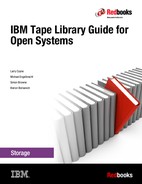
Figure 12-24 shows the Logical Libraries Graphical View.
Figure 12-24 TS4300 Logical Libraries Graphical View
12.10 Media
To ensure that your IBM Ultrium tape drive conforms to the IBM specifications for reliability, use IBM LTO Ultrium tape cartridges. You can use other LTO-certified data cartridges, but they might not meet the standards of reliability that have been established by IBM.
12.10.1 Data cartridges
All sixth generations contain ½-inch, dual-coated, metal-particle tape. Table 12-5 lists the native data capacity of Ultrium data cartridges.
Table 12-5 Ultrium native capacity
|
Data cartridge
|
Native data capacity
|
|
Ultrium 8 and WORM
|
12 TB (30 TB at a 2.5:1 compression ratio)
|
|
Ultrium 7 using format M8 for LTO 8
|
9 TB (22.5 TB at a 2.5:1 compression ratio)
|
|
Ultrium 7 and WORM
|
6 TB (15 TB at a 2.5:1 compression ratio)
|
|
Ultrium 6 and WORM
|
2.5 TB (6.25 TB at a 2.5:1 compression ratio)
|
|
Ultrium 5 and WORM
|
1.5 TB (3.0 TB at a 2:1 compression ratio)
|
|
Ultrium 4 and WORM
|
800 GB (1.6 TB at a 2:1 compression ratio)
|
|
Ultrium 3 and WORM
|
400 GB (800 GB at a 2:1 compression ratio)
|
|
Ultrium 2
|
200 GB (400 GB at a 2:1 compression ratio)
|
|
Ultrium 1
|
100 GB (200 GB at a 2:1 compression ratio)
|
Table 12-6 shows the compatibility among the six types of Ultrium cartridges.
Table 12-6 Ultrium compatibility among the generations
|
IBM Ultrium
|
IBM LTO Ultrium data cartridge
|
||||||
|
|
12 TB
(Ultrium 8)
|
9 TB
(Ultrium 7 M8 format)
|
6 TB
(Ultrium 7)
|
2.5 TB
(Ultrium 6)
|
1.5 TB
(Ultrium 5)
|
800 GB
(Ultrium 4)
|
400 GB
(Ultrium 3)
|
|
Ultrium 8
|
Read/write
|
Read/write
|
Read/write
|
|
|
|
|
|
Ultrium 7
|
|
|
Read/write
|
Read/write
|
Read only
|
|
|
|
Ultrium 6
|
|
|
|
Read/write
|
Read/write
|
Read only
|
|
|
Ultrium 5
|
|
|
|
|
Read/write
|
Read/write
|
Read only
|
|
Ultrium 4
|
|
|
|
|
|
Read/write
|
Read/write
|
|
Ultrium 3
|
|
|
|
|
|
|
Read/write
|
For more information about tape cartridges, see 2.1.4, “Tape cartridge” on page 53.
|
Note: LTO7 media with the M8 format can only be used on LTO 8 drives, and cannot be reformatted for read in an LTO7 drive.
Using M8 media requires that the latest version of drive and library FW to be installed. For more information, see “M8 format” on page 74.
|
Write Once Read Many media
Certain records retention and data security applications require a WORM method for storing data on tape. To meet this data storage requirement, a WORM feature is available on IBM LTO Ultrium generation 8, 7, 6, 5, 4, and 3 drives. You can enable the WORM feature by upgrading to WORM-capable drive firmware and using a special WORM tape cartridge.
A specially formatted WORM tape cartridge is required because standard read/write media are incompatible with the WORM feature. Each WORM cartridge has a unique, worldwide cartridge identifier (WWCID), which comprises the unique Cartridge Memory (CM) chip serial number and the unique tape media serial number.
For more information about WORM media, see “WORM tape format” on page 51.
12.10.2 Cleaning cartridges
A specially labeled IBM LTO Universal Ultrium Cleaning Cartridge cleans the drive in your library.
The drive determines when a head needs cleaning and communicates this information to the library. When the cleaning is finished, the drive ejects the cartridge, and the picker takes the cartridge and places it back in any storage slot. To remove a cleaning cartridge, export it from the library.
The IBM Cleaning Cartridge is valid for 50 uses. The Linear Tape-Open Cartridge Memory (LTO-CM) chip of the cartridge tracks the number of times that the cartridge is used.
12.10.3 Cartridge memory chip
All generations of the IBM LTO Ultrium data cartridges include an LTO-CM chip. This chip contains information about the cartridge and the tape (such as the name of the manufacturer that created the tape), and statistical information about the use of the cartridge.
The LTO-CM also helps to determine the reliability of the cartridge by storing data about its age, the number of times it was loaded, and the number of errors it accumulated. Whenever a tape cartridge is unloaded, the tape drive writes any pertinent information to the cartridge memory. The storage capacity of the Ultrium 6 Tape Cartridge Memory Chip is 16320 bytes.
12.11 Supported environments
For a current list of supported server platforms, operating systems, host bus adapters, SCSI adapters, and SAN switches, see the System Storage Interoperation Center (SSIC) page at this website:
On the page, under Storage Family, select IBM System Storage LTO Ultrium Tape. Then, select the product model for the TS4300 tape library and the version.
12.11.1 Supported storage software
For a current list of host software versions and release levels that support the TS4300 tape library, see the SSIC at this website:
For more information about LTO and backup applications, see this website and select Independent Software Vendor (ISV):
12.12 Specifications
This section describes the physical specifications and the operating environment for the TS4300 tape library.
12.12.1 Timings
The following timings are approximate and are provided as indicative values:
•To perform an inventory of a 3U library: 50 seconds
•To perform an inventory of a 21U library: 362 seconds
•To mount a cartridge in a 3U library: 14 seconds
•To mount a cartridge in a 21U library: 40 seconds
12.12.2 Physical specifications
Physical specifications are provided for the L5B module stand-alone and the 14-U library configuration.
Model L3A
A 3-U library configuration has the following physical specifications:
•Width: 475 mm (18.7 in)
•Depth: 892 mm (35.12 in)
•Height: 133.35 mm (5.25 in)
•Weight: 25 kg (55.12 lbs)
•Maximum configuration: Three Half-High drives and two power supplies
Model L3A
A 3-U library configuration has the following physical specifications:
•Width: 475 mm (18.7 in)
•Depth: 892 mm (35.12 in)
•Height: 133.35 mm (5.25 in)
•Weight: 18 kg (39.68 lbs)
•Maximum configuration: Three Half-High drives and two power supplies
12.12.3 Operating environment
The following operating environments are supported for all library configurations:
•Temperature: 10 - 35 degrees C (50 - 95 degrees F)
•Relative Humidity: 20 - 80%
•Maximum Wet Bulb (Caloric Value): 26 degrees C, 79 degrees F
•Electrical Power: 0.35 kVA
•Sound Power Level (LwAd): 6.6 Bels idle, 6.8 Bels operating
12.13 Feature codes
The TS4300 can be ordered with the optional features listed in Table 12-7. For more information, see the TS4300 tape library page at this website:
Table 12-7 Optional features
|
Description
|
Machine
|
Model
|
Feature
|
Comment
|
|
TS4300 tape library
|
3555
|
L3A
E3A
|
N/A
|
Base module
Expansion module
|
|
Library and Drive Code update
|
3555
|
L3A / E3A
|
0500
|
Library and drive code update by an IBM Service
Representative
|
|
Redundant power supply
|
3555
|
L3A / E3A
|
1900
|
Optional. Each module includes one PDU and supports two PDUs
|
|
Path failover
|
3555
|
L3A / E3A
|
1682
|
Optional. Data and Control Path failover
|
|
LTO Lib Managed Encryption
|
3555
|
L3A / E3A
|
5900
|
Required for SME and LME
|
|
Rack mount kit
|
3555
|
L3A / E3A
|
7002
|
Hardware that is required to mount a library in a rack
|
|
Driveless Library Unit
|
3555
|
E3A
|
9001
|
Order expansion without tape drives
|
|
LTO-6 HH FC drive
|
3555
|
L3A / E3A
|
AGKF
|
LTO-6 Half-High Fibre Channel Drive
|
|
LTO-6 HH SAS drive
|
3555
|
L3A / E3A
|
AGKG
|
LTO-6 Half-High SAS Drive
|
|
LTO-6 FH FC drive
|
3555
|
L3A / E3A
|
AGKH
|
LTO-6 Full-High Fibre Channel Drive
|
|
LTO-7 HH FC drive
|
3555
|
L3A / E3A
|
AGKJ
|
LTO-7 Half-High Fibre Channel Drive
|
|
LTO-7 HH SAS drive
|
3555
|
L3A / E3A
|
AGKK
|
LTO-7 Half-High SAS Drive
|
|
LTO-7 FH FC drive
|
3555
|
L3A / E3A
|
AGKL
|
LTO-7 Full-High Fibre Channel Drive
|
|
LTO-8 HH FC drive
|
3555
|
L3A / E3A
|
AGKM
|
LTO-8 Half-High Fibre Channel Drive
|
|
LTO-8 HH SAS drive
|
3555
|
L3A / E3A
|
AGKN
|
LTO-8 Half-High SAS Drive
|
|
LTO-8 FH FC drive
|
3555
|
L3A / E3A
|
AGKP
|
LTO-8 Full-High Fibre Channel Drive
|
12.13.1 Power cords
The following power cord features are available:
•9800 9-foot (2.8 m) Power Cord, 125 V, 15 A US and Canada
•9820 9-foot (2.8 m) Power Cord, 250 V, 16 A (AC) France and Germany
•9821 9-foot (2.8 m) Power Cord, 250 V, 11 A Denmark
•9825 9-foot (2.8 m) Power Cord, 250 V, 13 A UK and China
•9827 9-foot (2.8 m) Power Cord, 250 V, 6-16 A Israel
•9828 9-foot (2.8 m) Power Cord, 255 V, 10 A Switzerland
•9829 9-foot (2.8 m) Power Cord, 250 V, 16 A South Africa
•9830 9-foot (2.8 m) Power Cord, 250 V, 10 and 16 A Italy
•9831 9-foot (2.8 m) Power Cord, 250 V, 10 A Australia/NZ
•9833 9-foot (2.8 m) Power Cord, 250 V, 15 A US and Canada
•9834 9-foot (2.8 m) Power Cord, 250 V, 10 A Uruguay
•9835 9-foot (2.8 m) Power Cord, 125 V, 15 A Taiwan
•9840 9-foot (2.8 m) Power Cord, 250 V, 10 A China (PRC)
•9841 9-foot (2.8 m) Power Cord, 250 V, 10 A Taiwan
•9842 9-foot (2.8 m) Power Cord, 125 V, 12 A Japan
•9843 9-foot (2.8 m) Power Cord, 250 V, 12 A Japan
•9844 9-foot (2.8 m) Power Cord, 250 V, 12 A Korea
•9845 9-foot (2.8 m) Power Cord, 250 V, 10 A India
•9847 9-foot (2.8 m) Power Cord, 250 V, 10 A Brazil
12.13.2 Fibre Channel cables
The Fibre Channel tape drive has an LC connector. A cable is required to connect this connector directly to a system HBA or a SAN switch. The following feature codes are available:
•6005: 5 m (16.4 ft.) LC-LC Fibre Channel Cable
•6013: 13 m (42.7 ft.) LC-LC Fibre Channel Cable
•6025: 25 m (82 ft.) LC-LC Fibre Channel Cable
•5096: LC-SC Fibre Interposer
12.13.3 SAS cables
The SAS tape drive has a mini-SAS connector. A cable is required to connect this connector directly to a SAS HBA. The following feature codes are available:
•5400: SAS/Mini-SAS 4x Interposer
•5402: 2 m SAS/Mini-SAS 1x Cable
•5406: 5.5 m SAS/Mini-SAS 1x Cable
•5500: Mini-SAS/Mini-SAS 4x Interposer
•5502: 2 m Mini-SAS/Mini-SAS 1x Cable
•5507: 4 m Mini-SAS HD/Mini-SAS 1x Cable
•5509: 3 m Mini-SAS HD/Mini-SAS 2x Cable
12.13.4 Publications
The following publications are included with the Model L3A hardware:
•IBM TS4300 Tape Library Getting Started Guide, SC27-4630
•IBM TS4300 Tape Library Machine Type 3555 Users Guide, SC27-4629
•IBM Tape Device Drivers Installation and User’s Guide, GC27-2130
..................Content has been hidden....................
You can't read the all page of ebook, please click here login for view all page.