
2
Editing Scenes and Game Objects
In this chapter, we will develop some base knowledge of Unity in order to edit a project, and learn how to use several Unity editor windows to manipulate our first scene and its objects. We will also learn how an object, or GameObject, is created and composed, and how to manage complex scenes with multiple objects using Hierarchies and Prefabs. Finally, we will review how we can properly save all our work to continue working on it later.
Specifically, we will examine the following concepts in this chapter:
- Manipulating scenes
- GameObjects and components
- Object Hierarchies
- Prefabs
- Saving scenes and projects
Manipulating scenes
A scene is one of the several types of files (also known as assets) in our project. A “scene” can be used for different things according to the type of project, but the most common use case is to separate your game into whole sections, the most common ones being the following:
- Main menu
- Level 1, Level 2, Level 3, etc.
- Victory screen and lose screen
- Splash screen and loading screen
In this section, we will cover the following concepts related to scenes:
- The purpose of a scene
- The Scene View
- Adding our first GameObject to the scene
- Navigating the Scene View
- Manipulating GameObjects
So, let’s take a look at each of these concepts.
The purpose of a scene
The idea of separating your game into scenes is so that Unity can process and load just the data needed for the scene. Let’s say you are in the main menu; in such a case, you will have only the textures, music, and objects that the main menu needs loaded in random-access memory (RAM), the device’s main memory. In that case, there’s no need for your game to have loaded the Level 10 boss if you don’t need it right now. That’s why loading screens exist, just to fill the time between unloading the assets needed in one scene and loading the assets needed in another. Maybe you are thinking that open-world games such as Grand Theft Auto don’t have loading screens while you roam around in the world, but they are actually loading and unloading chunks of the world in the background as you move, and those chunks are different scenes that are designed to be connected to each other.
The difference between the Main Menu and a regular level scene is the objects (also known as GameObjects in the Unity lingo) they have. In a menu, you will find objects such as backgrounds, music, buttons, and logos, and in a level, you will have the player, enemies, platforms, health boxes, and so on. So, the meaning of your scene depends on what GameObjects are put into it. But how can we create a scene? Let’s start with the Scene View.
The Scene View
When you open a Unity project, you will see the Unity editor. It will be composed of several windows or panels, each one helping you to change different aspects of your game. In this chapter, we will be looking at the windows that help you create scenes. The Unity editor is shown in the following screenshot:
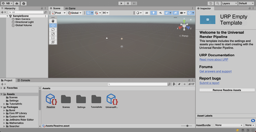
Figure 2.1: The Unity editor
If you have ever programmed any kind of application before, you are probably used to having a starting function such as Main, where you start writing code to create several objects needed for your app. If we are talking about games, you probably create all the objects for the scene there. The problem with this approach is that in order to ensure all objects are created properly, you will need to run the program to see the results, and if something is misplaced, you will need to manually change the coordinates of the object, which is a slow and painful process. Luckily, in Unity, we have the Scene View, an example of which is shown in the following screenshot:
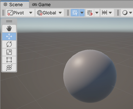
Figure 2.2: The Scene View
This window is an implementation of the classic WYSIWYG (What You See Is What You Get) concept. Here, you can create objects and place them all over the scene, all through a scene previsualization where you can see how the scene will look when you hit Play. But before learning how to use this scene, we need to have an object in the scene, so let’s create our first object.
Adding our first GameObject to the scene
The project template we chose when creating the project comes with a blank scene ready to work with, but let’s create our own empty scene to see how to do it ourselves. To do that, you can simply use the File | New Scene menu to create an empty new scene, as illustrated in the following screenshot:
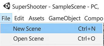
Figure 2.3: Creating a new scene
After clicking New Scene, you will see a window to pick a scene template; here, select the Basic (URP) template. A template defines which objects the new scene will have, and in this case, our template will come with a basic light and a camera, which will be useful for the scene we want to create. Once selected, just click the Create button:

Figure 2.4: Selecting the scene template
Now that we have our empty scene, let’s add GameObjects to it. We will learn several ways of creating GameObjects throughout the book, but for now, let’s start using some basic templates Unity provides us. In order to create them, we will need to open the GameObject menu at the top of the Unity window, and it will show us several template categories, such as 3D Object, 2D Object, Effects, and so on, as illustrated in the following screenshot:

Figure 2.5: Creating a cube
Under the 3D Object category, we will see several 3D primitives such as Cube, Sphere, Cylinder, and so on, and while using them is not as exciting as using beautiful, downloaded 3D models, remember that we are only prototyping our level at the moment. This is called gray-boxing, which means that we will use lots of prototyping primitive shapes to model our level so that we can quickly test it and see if our idea is good enough to start the complex work of converting it to a final version.
I recommend you pick the Cube object to start because it is a versatile shape that can represent lots of objects. So, now that we have a scene with an object to edit, the first thing we need to learn to do with the Scene View is to navigate through the scene.
Navigating the Scene View
In order to manipulate a scene, we need to learn how to move through it to view the results from different perspectives. There are several ways to navigate the scene, so let’s start with the most common one, the first-person view. This view allows you to move through the scene using a first-person-shooter-like navigation, using the mouse and the WASD keys. To navigate like this, you will need to press and hold the right mouse button, and while doing so, you can:
- Move the mouse to rotate the camera around its current position
- Press the WASD keys to move the position of the camera, always holding the right click
- You can also press Shift to move faster
- Press the Q and E keys to move up and down
Another common way of moving is to click an object to select it (the selected object will have an orange outline), and then press the F key to focus on it, making the Scene View camera immediately move into a position where we can look at that object more closely. After that, we can press and hold the left Alt key on Windows, or Option on Mac, along with the left mouse click, to finally start moving the mouse and “orbit” around the object. This will allow you to see the focused object from different angles to check every part of it is properly placed, as demonstrated in the following screenshot:

Figure 2.6: Selecting an object
Now that we can move freely through the scene, we can start using the Scene View to manipulate GameObjects.
Manipulating GameObjects
Another use of the Scene view is to manipulate the locations of the objects. In order to do so, we first need to select an object, and then press the Transform tool in the top-left corner of the Scene View. You can also press the Y key on the keyboard once an object is selected to do the same:
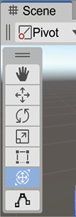
Figure 2.7: The transformation tool
This will show what is called the Transform gizmo over the selected object. A gizmo is a visual tool overlaid on top of the selected object, used to modify different aspects of it. In the case of the Transform Gizmo, it allows us to change the position, rotation, and scale of the object, as illustrated in Figure 2.8. Don’t worry if you don’t see the cube-shaped arrows outside the sphere—we will be enabling them in a moment:

Figure 2.8: The Transform gizmo
Let’s start translating the object, which is accomplished by dragging the red, green, and blue arrows inside the gizmo’s sphere. While you do this, the object will be moving along the selected axis. An interesting concept to explore here is the meaning of the colors of these arrows. If you pay attention to the top-right area of the Scene View, you will see an axis gizmo that serves as a reminder of those colors’ meaning, as illustrated in the following screenshot:

Figure 2.9: The axis gizmo
Computer graphics use the classic 3D Cartesian coordinate system to represent objects’ locations. The red color is associated with the x axis of the object, green with the y axis, and blue with the z axis.
But what does each axis mean? If you are used to another 3D authoring program, this can be different, but in Unity, the z axis represents the Forward Vector, which means that the arrow is pointing along the front of the object; the x axis is the Right Vector, and the y axis represents the Up Vector.
These directions are known as local coordinates, and that’s because every object can be rotated differently, meaning each object can be pointing its forward, up, and right vectors elsewhere according to its orientation. The local coordinates will make more sense when used later in the Object Hierarchies section of the chapter, so bear with me on that, but it’s worth discussing global coordinates now. The idea is to have a single origin point (the zero point) with a single set of forward, right, and up axes that are common across the scene. This way, when we say the object has a global position of 5,0,0, we know that we are referring to a position 5 meters along the global x-axis, starting from the global zero position. The global axes are the ones you see in the top-right axis gizmos previously mentioned.
In order to be sure that we are working with local coordinates, meaning we will move the object along its local axes, make sure the Local mode is activated in the Scene View, as shown in the following screenshot:

Figure 2.10: Switching pivot and local coordinates
If the right button says Global instead of Local, just click it and select Local from the dropdown options. By the way, try to keep the left button as Pivot. If it says Center, click and select Pivot. The pivot of the object is not necessarily its center, and that depends entirely on the 3D model we are using, where the author of it will specify where the object rotation center is located. For example, a car could have its pivot in the middle of its back wheels, so when we rotate, it will respect the real car’s rotation center. Editing based on the object’s pivot will simplify our understanding of how rotating via C# scripts will work later in Chapter 6, Implementing Movement and Spawning. Also, now that we have enabled Local coordinates, you should see the cube-shaped arrows seen in Figure 2.8; we will use them in a moment to scale the cube.
I know—we are editing a cube, so there is no clear front or right side, but when you work with real 3D models such as cars and characters, they will certainly have those sides, and they must be properly aligned with those axes. If by any chance in the future you import a car into Unity and the front of the car is pointing along the x axis, you will need to make that model aligned along the z axis because the code that we will create to move our object will rely on that convention (but let’s keep that for later).
Now, let’s use this Transform gizmo to rotate the object using the three colored circles around it. If you click and drag, for example, the red circle, you will rotate the object along the x axis. If you want to rotate the object horizontally, based on the color-coding we previously discussed, you will probably pick the x axis—the one that is used to move horizontally—but, sadly, that’s wrong. A good way to look at the rotation is like the accelerator of a motorcycle: you need to take it and roll it. If you rotate the x axis like this, you will rotate the object up and down. So, in order to rotate horizontally, you would need to use the green circle or the y axis. The process is illustrated in the following screenshot:
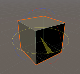
Figure 2.11: Rotating an object
Finally, we have scaling, and we have two ways to accomplish that, one of them being through the gray cube at the center of the Transform gizmo shown in Figure 2.8. This allows us to change the size of the object by clicking and dragging that cube. Now, as we want to prototype a simple level, sometimes we want to stretch the cube to create, for example, a column, or a flat floor, and here’s where the second way comes in.
If you click and drag the colored cubes in front of the translation arrows instead of the gray one in the center, you will see how our cube is stretched over those axes, allowing you to change the shape of the object. If you don’t see those cube-shaped arrows, remember to enable Local coordinates as stated earlier in this section.
The process to stretch is illustrated in the following screenshot:

Figure 2.12: Scaling an object
Remember you can also use the gray cube in the middle to scale all axes at the same time if desired, also known as uniform scaling, the same gray cube we had in the Transform gizmo.
Finally, something to consider here is that several objects can have the same scale values but have different sizes, given how they were originally designed. Scale is a multiplier we can apply to the original size of the object, so a building and a car both with scale 1 makes perfect sense; the relative size of one against the other seems correct. The main takeaway here is that scale is not size, but a way to multiply it.
Consider that scaling objects is usually a bad practice in many cases. In the final versions of your scene, you will use models with the proper size and scale, and they will be designed in a modular way so that you can plug them one next to the other. If you scale them, several bad things can happen, such as textures being stretched and becoming pixelated, and modules that no longer plug properly. There are some exceptions to this rule, such as placing lots of instances of the same tree in a forest and changing its scale slightly to simulate variation. Also, in the case of gray-boxing, it is perfectly fine to take cubes and change the scale to create floors, walls, ceilings, columns, and so on, because in the end, those cubes will be replaced with real 3D models.
Here’s a challenge! Create a room composed of a floor, three regular walls, and the fourth wall with a hole for a door (three cubes), and no need for a roof. In the next image you can see how it should look:
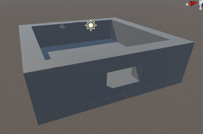
Figure 2.13: Room task finished
Now that we can edit an object’s location, let’s see how we can edit all its other aspects.
GameObjects and components
We talked about our project being composed of assets (the project’s files), and that a scene (which is a specific type of asset) is composed of GameObjects; so, how can we create an object? Through a composition of components.
In this section, we will cover the following concepts related to components:
- Understanding components
- Manipulating components
Let’s start by discussing what a component is.
Understanding components
A component is one of several pieces that make up a GameObject; each one is in charge of different features of the object. There are several components that Unity already includes that solve different tasks, such as playing a sound, rendering a mesh, applying physics, and so on; however, even though Unity has a large number of components, we will eventually need to create custom components sooner or later.
In the next image you can see what Unity shows us when we select a GameObject:
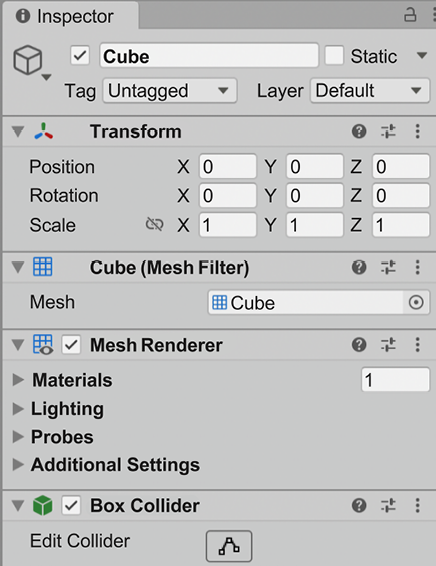
Figure 2.14: The Inspector panel
In the previous screenshot, we can see the Inspector panel. If we needed to guess what it does right now, we could say it shows all the properties of objects selected either via the Hierarchy or the Scene View, and allows us to configure those options to change the behavior of the object (i.e. the position and rotation, if it will project shadows or not, and so on). That is true, but we are missing a key element: those properties don’t belong to the object; they belong to the components of the object. We can see some titles in bold before a group of properties, such as Transform and Box Collider, and so on. Those are the components of the object.
In this case, our object has a Transform, a Mesh Filter, a Mesh Renderer, and a Box Collider component, so let’s review each one of those.
Transform just holds the position, rotation, and scale of the object, and by itself it does nothing—it’s just a point in our game—but as we add components to the object, that position starts to have more meaning. That’s because some components will interact with Transform and other components, each one affecting the other.
An example of that would be the case of Mesh Filter and Mesh Renderer, both of those being in charge of rendering a 3D model. Mesh Renderer will render the 3D model, also known as mesh, specified by the Mesh Filter in the position specified in the Transform component, so Mesh Renderer needs to get data from those other components and can’t work without them.
Another example would be the Box Collider. This represents the physics shape of the object, so when the physics calculates collisions between objects, it checks if that shape is colliding with other shapes based on the position specified in the Transform component.
We will explore rendering and physics later in the book, but the takeaway from this section is that a GameObject is a collection of components, each component adding a specific behavior to our object, and each one interacting with the others to accomplish the desired task. To further reinforce this, let’s see how we can convert a cube into a sphere that will fall due to gravity applied via physics.
Manipulating components
The tool to edit an object’s components is the Inspector. It not only allows us to change the properties of our components but also lets us add and remove components. In this case, we want to convert a cube to a sphere, so we need to change several aspects of those components.
We can start by changing the visual shape of the object, so we need to change the rendered model or mesh. The component that specifies the mesh to be rendered is the Mesh Filter component. If we look at it, we can see a Mesh property that says Cube, with a little circle and a dot on its right:

Figure 2.15: The Mesh filter component
If you don’t see a particular property, such as the Mesh we just mentioned, try to click the triangle at the left of the component’s name. Doing this will expand and collapse all the component’s properties.
If we click the button with a circle and a dot inside, the one at the right of the Mesh property, the Select Mesh window will pop up, allowing us to pick several mesh options. In this case, select the Sphere mesh. In the future, we will add more 3D models to our project so that the window will have more options.
The mesh selector is shown in the following screenshot:

Figure 2.16: The Mesh selector
Okay—the object now looks like a sphere, but will it behave like a sphere? Let’s find out. In order to do so, we can add a component named Rigidbody to our sphere, which will add physics to it. We will talk more about Rigidbody and physics later in Chapter 7, Physics Collisions and Health System, but for now, let’s stick to the basics.
In order to do so, we need to click the Add Component button at the bottom of the Inspector. It will show a Component Selector window with lots of categories; in this case, we need to click on the Physics category. The window will show all the Physics components, and there we can find the Rigidbody. Another option would be to type Rigidbody in the search box at the top of the window. The following screenshot illustrates how to add a component:
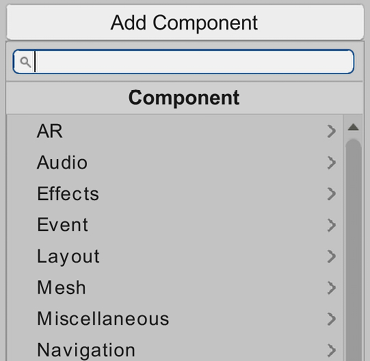
Figure 2.17: Adding components
If you hit the Play button in the top-middle part of the editor, you can test your sphere physics using the Game panel. That panel will be automatically focused when you hit Play and will show you how the player will see the game. The playback controls are shown in the following screenshot:

Figure 2.18: Playback controls
Here, you can just use the Transform gizmo to rotate and position your camera in such a way that it looks at our sphere. This is important as one problem that can happen is that maybe you won’t see anything during Play mode, and that can happen if the game camera is not pointing to where our sphere is located. While you are moving, you can check the little preview in the bottom-right part of the scene window to check out the new camera perspective. Another alternative would be to select the camera in the Hierarchy and use the shortcut Ctrl + Shift + F (or Command + Shift + F on a Mac). The camera preview is shown in the following screenshot:

Figure 2.19: The camera preview
Now, to test if physics collisions are executing properly, let’s create a cube, scale it until it has the shape of a ramp, and put that ramp below our sphere, as shown here:
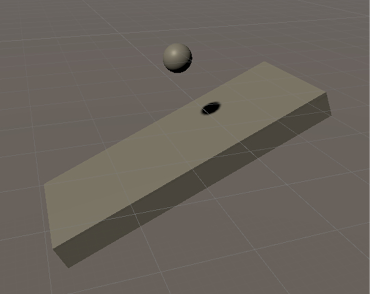
Figure 2.20: Ball and ramp objects
If you hit Play now, you will see the sphere colliding with our ramp, but in a strange way. It looks like it’s bouncing, but that’s not the case. If you expand the Box Collider component of our sphere, you will see that even if our object looks like a sphere, the green box gizmo is showing us that our sphere is actually a box in the physics world, as illustrated in the following screenshot:
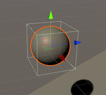
Figure 2.21: Object with sphere graphic and box collider
Nowadays, video cards (GPUs) can handle rendering highly detailed models (models with a high polygon count), but the physics system is executed in the central processing unit (CPU) and it needs to do complex calculations in order to detect collisions. To get a decent performance in our game, it needs to run at least 30 frames per second (FPS), the minimum accepted by the industry to provide a smooth experience. The physics system considers that, and hence it works using simplified collision shapes that may differ from the actual shape the player sees on the screen.
That’s why we have Mesh Filter and the different types of Collider components separated—one handles the visual shape and the other the physics shape.
Again, the idea of this section is not to deep-dive into those Unity systems, so let’s just move on for now. How can we solve our sphere actually being a box? Simple: by modifying our components! In this case, the Box Collider component already present in our cube GameObject can just represent a box physics shape, unlike Mesh Filter, which supports any rendering shape. So, first, we need to remove it by right-clicking the component’s title and selecting the Remove Component option, as illustrated in the following screenshot:
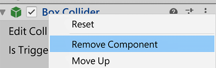
Figure 2.22: Removing components
Now, we can again use the Add Component menu to select a Physics component, this time selecting the Sphere Collider component. If you look at the Physics components, you will see other types of colliders that can be used to represent other shapes, but we will look at them later in Chapter 7, Physics Collisions and Health System. The Sphere Collider component can be seen in the following screenshot:
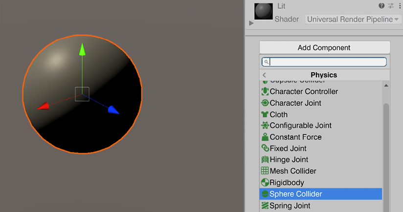
Figure 2.23: Adding a Sphere Collider component
So, if you hit Play now, you will see that our sphere not only looks like a sphere but also behaves like one. Remember: the main idea of this section of the book is understanding that in Unity you can create whatever object you want just by adding, removing, and modifying components, and we will be doing a lot of this throughout the book.
Now, components are not the only thing needed in order to create objects. Complex objects may be composed of several sub-objects, so let’s see how that works.
Object Hierarchies
Some complex objects may need to be separated into sub-objects, each one with its own components. Those sub-objects need to be somehow attached to the main object and work together to create the necessary object behavior.
In this section, we will cover the following concepts related to objects:
- Parenting of objects
- Possible uses
Let’s start by discovering how to create a parent-child relationship between objects.
Parenting of objects
Parenting consists of making an object the child of another, meaning that those objects will be related to each other. One type of relationship that happens is a Transform relationship, meaning that a child object will be affected by the parent’s Transform. In simple terms, the child object will follow the parent, as if it is attached to it. For example, imagine a player with a hat on their head. The hat can be a child of the player’s head, making the hat follow the head while they are attached.
In order to try this, let’s create a capsule that represents an enemy and a cube that represents the weapon of the enemy. Remember that in order to do so, you can use the GameObject | 3D Object | Capsule and Cube options and then use the Transform tool to modify them. An example of a capsule and a cube can be seen in the following screenshot:

Figure 2.24: A capsule and a cube representing an enemy and a weapon
If you move the enemy object (the capsule), the weapon (the cube) will keep its position, not following our enemy. So, to prevent that, we can simply drag the weapon to the enemy object in the Hierarchy window, as illustrated in the following screenshot:

Figure 2.25: Parenting the cube weapon to the capsule character
Now, if you move the enemy, you will see the gun moving, rotating, and being scaled along with it. So, basically, the gun Transform also has the effects of the enemy Transform component.
Now that we have done some basic parenting, let’s explore other possible uses.
Possible uses
There are some other uses of parenting aside from creating complex objects. Another common usage for it is to organize the project Hierarchy. Right now, our scene is simple, but in time it will grow, so keeping track of all the objects will become difficult. To prevent this, we can create empty GameObjects (in GameObject | Create Empty) that only have the Transform component to act as containers, putting objects into them just to organize our scene. Try to use this with caution because this has a performance cost if you abuse it. Generally, having one or two levels of parenting when organizing a scene is fine, but more than that can have a performance hit. Consider that you can—and will—have deeper parenting for the creation of complex objects; the proposed limit is just for scene organization.
To keep improving on our previous example, duplicate the enemy a couple of times all around the scene, create an empty GameObject and name it Enemies, and drag all the enemies into it so that it will act as a container. This is illustrated in the following screenshot:

Figure 2.26: Grouping enemies in a parent object
Another common usage of parenting is to change the pivot (or center) of an object. Right now, if we try to rotate our gun with the Transform gizmo, it will rotate around its center because the creator of that cube decided to put the center there. Normally, that’s okay, but let’s consider the case where we need to make the weapon aim at the point where our enemy is looking. In this case, we need to rotate the weapon around the weapon handle; so, in the case of this cube weapon, it would be the closest end to the enemy. The problem here is that we cannot change the center of an object, so one solution would be to create another “weapon” 3D model or mesh with another center, which will lead to lots of duplicated versions of the weapon if we consider other possible gameplay requirements such as a rotating weapon pickup. We can fix this easily using parenting.
The idea is to create an empty GameObject and place it where we want the new pivot of our object to be. After that, we can simply drag our weapon inside this empty GameObject, and, from now on, consider the empty object as the actual weapon.
If you rotate or scale this weapon container, you will see that the weapon mesh will apply those transformations around this container, so we can say the pivot of the weapon has changed (actually, it hasn’t, but our container simulates the change). The process is illustrated in the following screenshot:
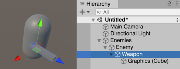
Figure 2.27: Changing the weapon pivot
Now, let’s continue seeing different ways of managing GameObjects, using Prefabs this time.
Prefabs
In the previous example, we created lots of copies of our enemy around the scene, but in doing so, we have created a new problem. Let’s imagine we need to change our enemy and add a Rigidbody component to it, but because we have several copies of the same object, we need to take them one by one and add the same component to all of them. Maybe later, we will need to change the mass of each enemy, so again, we need to go over each one of the enemies and make the change, and here we can start to see a pattern. One solution could be to select all the enemies using the Ctrl key (Command on a Mac) and modify all of them at once, but that solution won’t be of any use if we have enemy copies in other scenes. So, here is where Prefabs come in.
In this section, we will cover the following concepts related to Prefabs:
- Creating Prefabs
- Prefab-instance relationship
- Prefab variants
Let’s start by discussing how to create and use Prefabs.
Creating Prefabs
Prefabs are a Unity tool that allows us to convert custom-made objects, such as our enemy, into an asset that defines how they can be created. We can use them to create new copies of our custom object easily, without needing to create its components and sub-objects all over again.
In order to create a Prefab, we can simply drag our custom object from the Hierarchy window to the project window, and after doing that you will see a new asset in your project files. The project window is where you can navigate and explore all your project files; so, in this case, our Prefab is the first Asset we ever created. Now, you can simply drag the Prefab from the project window into the scene to easily create new Prefab copies, as illustrated in the following screenshot:

Figure 2.28: Creating a Prefab
Now, we have a little problem here. If you pay attention to the Hierarchy window, you will see the original Prefab objects and all the new copies with their names in the color blue, while the enemies created before the Prefab will have their names in black. The blue color in a name means that the object is an instance of a prefab, meaning that the object was created based on a Prefab. We can select those blue-named objects and click the Select button in the Inspector to select the original Prefab that created that object. This is illustrated in the following screenshot:

Figure 2.29: Detecting prefabs in the Hierarchy
So, the problem here is that the previous copies of the Prefab are not instances of the Prefab we just created, and sadly there’s no way to connect them to it. So, in order to make that happen, we need to simply destroy the old copies and replace them with copies created with the Prefab. At first, not having all copies as instances doesn’t seem to be a problem, but it will be in the next section of this chapter, where we will explore the relationship between the Prefabs and their instances.
Prefab-instance relationship
An instance of a Prefab, the GameObject created when dragging the Prefab to the scene, has a binding to it that helps to revert and apply changes easily between the prefab and the instance. If you take a Prefab and make some modifications to it, those changes will be automatically applied to all instances across all the scenes in the project, so we can easily create a first version of the Prefab, use it all around the project, and then experiment with changes.
To practice this, let’s say we want to add a Rigidbody component to the enemies so that they can fall. In order to do so, we can simply double-click the Prefab file in the Project panel and we will enter the Prefab Edit Mode, where we can edit the Prefab isolated from the rest of the scene.
Here, we can simply take the Prefab root object (Enemy in our case) and add the Rigidbody component to it. After that, we can simply click on the Scenes button in the top-left part of the scene window to get back to the scene we were editing, and now, we can see that all the Prefab instances of the enemy have a Rigidbody component, as illustrated in the following screenshot:

Figure 2.30: Prefab edit mode
Now, what happens if we change a Prefab instance (the one in the scene) instead? Let’s say we want one specific enemy to fly, so they won’t suffer the effect of gravity. We can do that by simply selecting the specific Prefab and unchecking the Use Gravity checkbox in the Rigidbody component. After doing that, if we play the game, we will see that only that specific instance will float. That’s because changes to an instance of a Prefab become an override, a set of differences the instance has compared to the original prefab. We can see how the Use Gravity property is bold in the Inspector, and also has a blue bar displayed to its left, meaning it’s an override of the original Prefab value. Let’s take another object and change its Scale property to make it bigger. Again, we will see how the Scale property becomes bold and the blue bar at its left will appear. The Use Gravity checkbox can be seen in the following screenshot:
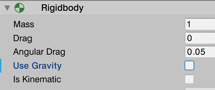
Figure 2.31: Use Gravity being highlighted as an override
The overrides have precedence over the Prefab, so if we change the scale of the original Prefab, the one that has a scale override won’t change, keeping its own version of the scale, as illustrated in the following screenshot:

Figure 2.32: One Prefab instance with a scale override
We can easily locate all overrides of an instance using the Overrides dropdown in the Inspector after selecting the Prefab instance (the one in the scene, outside Prefab Edit Mode) in the Hierarchy, locating all changes our object has. It not only allows us to see all the overrides but also reverts any override we don’t want and applies the ones we do want. Let’s say we regretted the lack of gravity of that specific Prefab—no problem! We can just locate the override and revert it using the Revert button after clicking on the component with the override. The process is illustrated in the following screenshot:

Figure 2.33: Reverting a single override
Also, let’s imagine that we really liked the new scale of that instance, so we want all instances to have that scale—great! We can simply select the specific override, hit the Apply button, and then the Apply to Prefab option; now, all instances will have that scale (except the ones with an override), as illustrated in the following screenshot:

Figure 2.34: The Apply button
Also, we have the Revert All and Apply All buttons, but use them with caution, because you can easily revert and apply changes that you are not aware of.
So, as you can see, Prefabs are a really useful Unity tool to keep track of all similar objects and apply changes to all of them, and also have specific instances with few variations. Talking about variations, there are other cases where you will want to have several instances of a Prefab with the same set of variations—for example, flying enemies and grounded enemies—but if you think about that, we will have the same problem we had when we didn’t use Prefabs, so we need to manually update those varied versions one by one.
Here, we have two options: one is to create a brand new Prefab just to have another version with that variation. This leads to the problem that if we want all types of enemies to undergo changes, we need to manually apply the changes to each possible Prefab. The second option is to create a Prefab variant. Let’s review the latter.
Prefab variants
A Prefab variant is a new Prefab created based on an existing one, so the new one inherits the features of the base Prefab. This means that our new Prefab can have differences from the base one, but the features that they have in common are still connected.
To illustrate this, let’s create a variation of the enemy Prefab that can fly: the flying enemy Prefab. In order to do that, we can select an existing enemy Prefab instance in the Hierarchy window, name it Flying Enemy, and drag it again to the project window, and this time we will see a prompt, asking which kind of Prefab we want to create. This time, we need to choose Prefab Variant, as illustrated in the following screenshot:

Figure 2.35: Creating Prefab Variants
Now, we can enter the Prefab Edit Mode of the variant by double-clicking the new Prefab file created in the project panel, and then add a cube as the jetpack of our enemy, and also uncheck the Use Gravity property for the enemy. If we get back to the scene, we will see the variant instance being changed, and the base enemies aren’t changed. You can see this in the following screenshot:

Figure 2.36: A Prefab variant instance
Now, imagine you want to add a hat to all our types of enemies. We can simply enter the Prefab Edit Mode of the base enemy Prefab by double-clicking it and adding a cube as a hat. Now, we will see that change applied to all the enemies, because remember: the Flying Enemy Prefab is a variant of the base enemy Prefab, meaning that it will inherit all the changes of that one.
We have created lots of content so far, but if our PC turns off for some reason, we will certainly lose it all, so let’s see how we can save our progress.
Saving scenes and projects
As in any other program, we need to save our progress. The difference here is that we don’t have just one giant file with all the project assets, but several files for each asset.
Let’s start saving our progress by saving the scene, which is pretty straightforward. We can simply go to File | Save or press Ctrl + S (Command + S on a Mac). The first time we save our scene, a window will ask us where we want to save our file, and you can save it wherever you want inside the Assets folder of our project, but never outside that folder; otherwise, Unity will not be capable of finding it as an asset in the project. That will generate a new asset in the project window: a scene file. In the following screenshot you can see how I saved the scene, naming it test, and now it shows up in the Project panel:
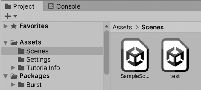
Figure 2.37: Scene files
We can create a folder to save our scene in the save dialog, or, if you already saved the scene, you can create a folder using the plus (+) icon in the project window and then click the Folder option. Finally, drag the created scene to that folder. Now, if you create another scene with the File | New Scene menu option, you can get back to the previous scene just by double-clicking the scene asset in the project window. Try it!
This only saved the scene, but any change in Prefabs and other kinds of assets are not saved with that option. Instead, if you want to save every change of the assets except scenes, you can use the File | Save Project option. It can be a little bit confusing, but if you want to save all your changes, you need to both save the scenes and the project, as saving just the project won’t save the changes to scenes. Sometimes, the best way to be sure everything is saved is just by closing Unity, which is recommended when you try to move your project between computers or folders. This will show you a prompt to save the changes on the scene, and will automatically save any change made to other assets, like Prefabs.
Summary
In this chapter, we saw a quick introduction to essential Unity concepts. We reviewed the basic Unity windows and how we can use all of them to edit a full scene, from navigating it, then creating premade objects (Prefabs), to manipulating them to create our own types of objects using GameObjects and components. We also discussed how to use the Hierarchy window to parent GameObjects to create complex object Hierarchies, as well as creating Prefabs to reutilize and manipulate large amounts of the same type of objects. Finally, we discussed how we can save our progress.
In the next chapter, we will learn different tools like the Terrain system and ProBuilder to create the first prototype of our game’s level. This prototype will serve as a preview of where our scene will be headed, testing some ideas before going into full production.