
6
Implementing Movement and Spawning
In the previous chapter, we learned about the basics of scripting, so now let’s create the first script for our game. We will see the basics of how to move objects through scripting using the Transform component, which will be applied to the movement of our player with the keyboard keys, the constant movement of bullets, and other object movements. Also, we will see how to create and destroy objects during the game, such as the bullets our player and enemy shoot and the enemy wave spawners. These actions can be used in several other scenarios, so we will explore a few to reinforce the idea.
In this chapter, we will examine the following scripting concepts:
- Implementing movement
- Implementing spawning
- Using the new Input System
We will start by scripting components to move our character through the keyboard, and then we will make our player shoot bullets. Something to consider is that we are going to first see the C# version and then show the Visual Scripting equivalent in each section.
Implementing movement
Almost every object in the game moves one way or another: the player character with the keyboard; the enemies through AI; the bullets that simply move forward; and so on. There are several ways of moving objects in Unity, so we will start with the simplest one, that is, through the Transform component.
In this section, we will examine the following movement concepts:
- Moving objects through
Transform - Using input
- Understanding Delta Time
First, we will explore how to access the Transform component in our script to drive the player movement, to later apply movement based on the player’s keyboard input. Finally, we are going to explore the concept of Delta Time to make sure the movement speeds are consistent on every computer. We are going to start learning about the Transform API to make a simple movement script.
Moving objects through Transform
Transform is the component that holds the translation, rotation, and scale of the object, so every movement system such as physics or pathfinding will affect this component. Sometimes, we want to move the object in a specific way according to our game by creating our own script, which will handle the movement calculations we need and modify Transform to apply them.
One concept implied here is that components alter other components. The main way of coding in Unity is to create components that interact with other components. Here, the idea is to create one that accesses another and tells it to do something: in this case, to move. To create a script that tells Transform to move, do the following:
- Create and add a script called
PlayerMovementto our character, like we did in the previous chapter. In this case, it would be the animated 3D model we downloaded previously (drag the 3D asset from the Project view to the scene). Remember to move the script to the Scripts folder after creation:

Figure 6.1: Creating a Player Movement script in the character
- Double-click the created script asset to open an IDE to edit the code.
- We are moving, and the movement is applied to every frame. So this script will use only the
Updatefunction or method, and we can removeStart(it is a good practice to remove the unused functions):

Figure 6.2: A component with just the Update event function
- To move our object along its local forward axis (z axis), add the
transform.Translate(0,0,1);line to theUpdatefunction, as shown in Figure 6.3:
Every component inherits a Transform field (to be specific, a getter) that is a reference to the Transform of the GameObject the component is placed in; it represents the sibling Transform of our component. Through this field, we can access the Translate function of the Transform, which will receive the offset to apply to the x, y, and z local coordinates.

Figure 6.3: A simple Move Forward script
- Save the file and play the game to see the movement. Ensure the camera is pointing at the character to properly see the effect of the script.
You will notice that the player is moving too fast. That’s because we are using a fixed speed of 1 meter, and because Update is executing all frames, we are moving 1 meter per frame. In a standard 30 FPS game, the player will move 30 meters per second, which is too much, but probably our computer is running the game with way more FPS than that. We can control the player’s speed by adding a speed field and using the value set in the editor instead of the fixed value of 1. You can see one way to do this in the Figure 6.4, but remember the other options we discussed in Chapter 5, Introduction to C# and Visual Scripting:

Figure 6.4: Creating a speed field and using it as the z speed of the movement script
Now if you save the script to apply the changes and set the Speed of the player in the Editor, you can play the game and see the results. In my case, I used 0.1, but you might need another value (more on this in the Understanding Delta Time section):
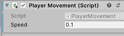
Figure 6.5: Setting speed of 0.1 meters per frame
Now, for the Visual Scripting version, first remember to not mix the C# and Visual Scripting versions of our scripts, not because it is not possible, but because we want to keep things simple for now. So, you can either delete the script from the player object and add the Visual Scripting version, or you can create two player objects and enable and disable them to try both versions. I recommend creating one project for the C# version of the scripts and then creating a second project to experiment with the Visual Script version.
The Visual Scripting Graph of this script will look like the following image:

Figure 6.6: Setting a speed of 0.1 meters per frame
As you can see, we added a Script Machine component to our Player GameObject. Then, we pressed the New button in the Script Machine component to create a new Graph called PlayerMovement. We also created a Float variable called speed with the value of 0.1. In the Graph, we added the On Update event node and attached it to the Translate (X,Y,Z) node of the Transform, which, similarly to the C# version, will move along the local axes of the object. Finally, we connected the Z parameter pin of Translate to the GetVariable node representing the speed we created in the GameObject. If you compare this Graph with the code we used in the C# version, they are essentially the same Update method and Translate function. If you don’t remember how to create this Graph, you can go back to Chapter 5, Introduction to C# and Visual Scripting, to recap the process.
You will notice that the player will move automatically. Now let’s see how to execute the movement based on player input such as the keyboard and mouse.
Using Input
Unlike NPCs, we want the player’s movement to be driven by the player’s input, based on which keys they press, the mouse movement, and so on. To know whether a certain key has been pressed, such as the Up arrow, we can use the Input.GetKey(KeyCode.W) line, which will return a Boolean, indicating whether the key specified in the KeyCode enum is pressed, which is W in this case. We can combine the GetKey function with an If statement to make the translation execute when the key is pressed.
Let’s start by implementing the keyboard movement by following these steps:
- Make the forward movement execute only when the W key is pressed with the code, as shown in the next screenshot:

Figure 6.7: Conditioning the movement until the W key is pressed
- We can add other movement directions with more
Ifstatements to move backward and A and D to move left and right, as shown in the following screenshot. Notice how we used the minus sign to inverse the speed when we needed to move in the opposite axis direction:

Figure 6.8: Checking the W, A, S, and D key pressure
- In case you also want to consider the arrow keys, you can use an
ORinsideif, as shown in the following screenshot:
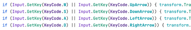
Figure 6.9: Checking the W, A, S, D, and arrow key pressure
- Save the changes and test the movement in Play mode.
Something to take into account is that, first, we have another way to map several keys to a single action by configuring the Input Manager—a place where action mappings can be created. Second, at the time of writing this, Unity has released a new Input System that is more extensible than this one.
For now, we will use this one because it is simple enough to make our introduction to scripting with Unity easier, but in games with complex input, it is recommended to look for more advanced tools.
Now, for the Visual Scripting version, the graph will look like this:

Figure 6.10: Input movement in Visual Scripting
As you can see, the graph has grown in size considerably compared to the C# version, which serves as an example of why developers prefer to code instead of using visual tools. Of course, we have several ways to split this graph into smaller chunks and make it more readable, and also consider I needed to squeeze the nodes together to be in the same image. Also, in the graph, we only see the example graph to move forward and backward, but you can easily extrapolate the necessary steps for lateral movement based on this one. As usual, you can also check the GitHub repository of the project to see the completed files.
Looking at the graph, you can quickly observe all the similarities to the C# version; we chained If nodes to the On Update event node in a way that if the first If node condition is true, it will execute the Translate in the player’s forward direction. If that condition is false, we chained the False output node to another If that checks the pressure of the other keys, and in that case, we moved backward using the Multiply (Scalar) node to inverse the speed.
You can notice nodes like If that have more than one Flow Output pin to branch the execution of the code.
You can also notice the usage of the GetKey (Key) node, the Visual Scripting version of the same GetKey function we used previously. When looking at this node in the Search box, you will see all the versions of the function, and in this case, we selected the GetKey(Key) version; the one that receives a name (string) works differently, and we are not covering that one:
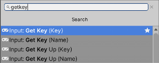
Figure 6.11: All versions of Input GetKey
We also used the Or node to combine the two GetKey (Key) functions into one condition to give to the If. These conditional operators can be found in the Logic category of the Search box:

Figure 6.12: The Boolean Logic operators
One thing to highlight is the usage of the Multiply node to multiply the value of the speed variable by –1. We needed to create a Float Literal node to represent the –1 value. Next, surely all programmers will notice some limitations regarding how we used the If node’s True and False output pins, but we will address that in a moment. Finally, consider that this implementation has the problem of blocking the second input read if the first is successful; we will discuss a way to fix this when we add rotation to our character later in this section.
Now, let’s implement the mouse controls. In this section, we will only cover rotation with mouse movement; we will shoot bullets in the next section: Implementing spawning. In the case of mouse movement, we can get a value saying how much the mouse has moved both horizontally and vertically. This value isn’t a Boolean but a number: a type of input usually known as an axis. The value of an axis will indicate the intensity of the movement, and the sign of that number will indicate the direction. For example, if Unity’s "Mouse X" axis says 0.5, it means that the mouse moved to the right with a moderate speed, but if it says -1, it moved quickly to the left, and if there is no movement, it will say 0. The same goes for sticks in gamepads; the axis named Horizontal represents the horizontal movement of the left stick in common joysticks, so if the player pulls the stick fully to the left, it will say -1.
We can create our own axes to map other common joystick pressure-based controls, but for our game, the default ones are enough. To detect mouse movement, follow these steps:
- Use the
Input.GetAxisfunction insideUpdate, next to the movementifstatements, as shown in the following screenshot, to store the value of this frame’s mouse movement into a variable:

Figure 6.13: Getting the horizontal movement of the mouse
- Use the
transform.Rotatefunction to rotate the character. This function receives the degrees to rotate in the x, y, and z axes. In this case, we need to rotate horizontally, so we will use the mouse movement value as the y-axis rotation, as shown in the next screenshot:

Figure 6.14: Rotating the object horizontally based on mouse movement
- If you save and test this, you will notice that the character will rotate but very quickly or slowly, depending on your computer. Remember, this kind of value needs to be configurable, so let’s create a
rotationSpeedfield to configure the speed of the player in the editor:
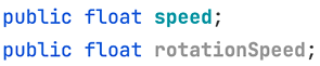
Figure 6.15: The speed and rotation speed fields
- Now we need to multiply the mouse movement value by the speed, so, depending on the
rotationSpeed, we can increase or reduce the rotation amount. As an example, if we set a value of0.5in the rotation speed, multiplying that value by the mouse movement will make the object rotate at half the previous speed, as shown in the following screenshot:

Figure 6.16: Multiplying the mouse movement by the rotation speed
- Save the code and go back to the editor to set the rotation speed value. If you don’t do this, the object won’t rotate because the default value of the float type fields is
0:

Figure 6.17: Setting the rotation speed
The Visual Scripting additions to achieve rotation will look like this:
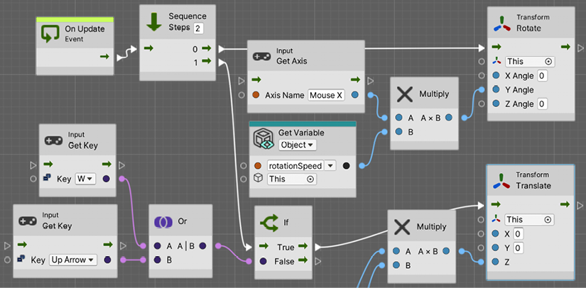
Figure 6.18: Rotating in Visual Scripting
The first thing to notice here is the usage of the Sequence node. An output pin can only be attached to one other node, but in this case, On Update needs to do two different things, to rotate and to move, each one being independent of the other. Sequence is a node that will execute all its output pins one after the other, regardless of the results of each one. You can specify the number of output pins in the Steps input box; in this example, two is enough.
In the output pin 0, the first one, we added the rotation code, which is pretty self-explanatory given it is essentially the same as the movement code with slightly different nodes (Rotate (X, Y, Z) and GetAxis). Then, to Output Pin 1, we attached the If that checks the movement input—the one we did at the beginning of this section. This will cause the rotation to be executed first and the movement second.
Regarding the limitation we mentioned before, it’s basically the fact we cannot execute both Forward and Backward rotations, given that if the forward movement keys are pressed, the first If will be true. Because the backward key rotation is checked in the false output pin, they won’t be checked in such cases. Of course, as our first movement script it might be enough but consider the lateral movement. If we continue the If chaining using True and False output pins, we will have a scenario where we can only move in one direction. So we cannot combine, for example, Forward and Right to move diagonally.
A simple solution to this issue is to put the If nodes in the sequence instead of chaining them, so all the If nodes are checked, as the original C# did. You can see an example of this in the next image:
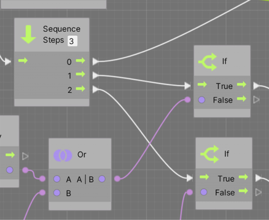
Figure 6.19: Sequencing Ifs
Something to consider here is that the chaining of the Ifs and any kind of node can be removed by right-clicking the circle pins on both ends of the line that connects them. Now that we have completed our movement script, we need to refine it to work in every machine by exploring the concept of Delta Time.
Understanding Delta Time
Unity’s Update loop executes as fast as the computer can. You can specify in Unity the desired frame rate, but achieving that depends exclusively on whether your computer can reach that, which depends on lots of factors, not only hardware, so you cannot expect to always have consistent FPS. You must code your scripts to handle every possible scenario. Our current script is moving at a certain speed per frame, and the per frame part is important here.
We have set the movement speed to 0.1, so if my computer runs the game at 120 FPS, the player will move 12 meters per second. Now, what happens on a computer where the game runs at 60 FPS? As you may guess, it will move only 6 meters per second, making our game have inconsistent behavior across different computers. This is where Delta Time saves the day.
Delta Time is a value that tells us how much time has passed since the previous frame. This time depends a lot on our game’s graphics, number of entities, physics bodies, audio, and countless aspects that will dictate how fast your computer can process a frame. As an example, if your game runs at 10 FPS, it means that, in a second, your computer can process the Update loop 10 times, meaning that each loop takes approximately 0.1 seconds; in the frame, Delta Time will provide that value. In the next diagram, you can see an example of 4 frames taking different times to process, which can happen in real-life cases:

Figure 6.20: Delta Time values varying in different frames of the game
Here, we need to code in such a way as to change the per frame part of the movement to per second; we need to have consistent movement per second across different computers. A way to do that is to move proportionally to the Delta Time: the higher the Delta Time value, the longer that frame is, and the further the movement should be to match the real time that has passed since the last update. We can think about our speed field’s current value in terms of 0.1 meters per second; our Delta Time saying 0.5 means that half a second has passed, so we should move half the speed, 0.05.
After two frames a second have passed, the sum of the movements of the frames (2 x 0.05) matches the target speed, 0.1. Delta Time can be interpreted as the percentage of a second that has passed.
To make the Delta Time affect our movement, we should simply multiply our speed by Delta Time every frame because the Delta Time can be different every frame, so let’s do that:
- We access Delta Time using Time.deltaTime. We can start affecting the movement by multiplying the Delta Time in every Translate:

Figure 6.21: Multiplying speed by Delta Time
- We can do the same with the rotation speed, by chaining the mouse and speed multiplications:

Figure 6.22: Applying Delta Time to the rotation code
- If you save and play the game, you will notice that the movement will be slower than before. That’s because now
0.1is the movement per second, meaning10centimeters per second, which is pretty slow; try raising those values. In my case,10for speed and180for rotation speed was enough, but the rotation speed depends on the player’s preferred sensibility, which can be configurable, but let’s keep that for another time.
The Visual Scripting change for rotation will look like this:

Figure 6.23: Applying Delta Time to Rotate Visual Script
For movement, you can easily extrapolate from this example or remember to check the project on GitHub. We simply chained another Multiply node with Get Delta Time.
We just learned how to mix the Input System of Unity, which tells us about the state of the keyboard, mouse, and other input devices, with the basic Transform movement functions. This way, we can start making our game feel more dynamic.
Now that we have finished the player’s movement, let’s discuss how to make the player shoot bullets using Instantiate functions.
Implementing spawning
We have created lots of objects in the editor that define our level, but once the game begins, and according to the player’s actions, new objects must be created to better fit the scenarios generated by player interaction. Enemies might need to appear after a while, or bullets must be created according to the player’s input; even when enemies die, there’s a chance of spawning a power-up. This means that we cannot create all the necessary objects beforehand but should create them dynamically, and that’s done through scripting.
In this section, we will examine the following spawning concepts:
- Spawning objects
- Timing actions
- Destroying objects
We will start seeing the Unity Instantiate function, which allows us to create instances of Prefabs at runtime, such as when pressing a key, or in a time-based fashion, such as making our enemy spawn bullets once every certain amount of time. Also, we will learn how to destroy these objects to prevent our scene from starting to perform badly due to too many objects being processed.
Let’s start with how to shoot bullets according to the player’s input.
Spawning objects
To spawn an object in runtime or Play mode, we need a description of the object, which components it has, and its settings and possible sub-objects. You might be thinking about Prefabs here, and you are right; we will use an instruction that will tell Unity to create an instance of a Prefab via scripting. Remember that an instance of a Prefab is an object created based on the Prefab—basically a clone of the original one.
We will start with shooting player’s bullets, so first let’s create the bullet Prefab by following these steps:
- Create a sphere in GameObject | 3D Object | Sphere. You can replace the sphere mesh with another bullet model if you want, but we will keep the sphere in this example for now.
- Rename the sphere
Bullet. - Create a material by clicking on the + button of the Project window, choosing the option Material, and calling it
Bullet. Remember to place it inside theMaterialsfolder. - Check the Emission checkbox in the material and set the Emission Map and Base Map colors to red. Remember, the emission color will make the bullet shine, especially with the bloom effect in our post-processing volume:

Figure 6.24: Creating a red bullet material with emission color
- Apply the Material to the Sphere by dragging the material to it.
- Set the Scale to a smaller value—
0.3, 0.3, 0.3worked in my case. - Create a script called
ForwardMovementto make the bullet constantly move forward at a fixed speed. You can create it both with C# and Visual Scripting, but for simplicity, we are only going to use C# in this case.I suggest you try to solve this by yourself first and look at the screenshot in the next step with the solution later as a little challenge to recap the movement concepts we saw previously. If you don’t recall how to create a script, please look at Chapter 5, Introduction to C# and Visual Scripting, and check the previous section to see how to move objects.
- The next screenshot shows you what the script should look like:

Figure 6.25: A simple ForwardMovement script
- Add the script (if not already there) to the bullet and set the speed to a value you see fit. Usually, bullets are faster than the player but that depends on the game experience you want to get. In my case,
20worked fine. Test it by placing the bullet near the player and playing the game:
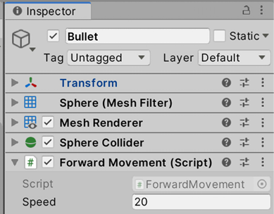
Figure 6.26: A ForwardMovement script in the bullet
- Drag the bullet
GameObjectinstance to thePrefabsfolder to create a Bullet Prefab. Remember that the Prefab is an asset that has a description of the created bullet, like a blueprint of how to create a bullet:

Figure 6.27: Creating a Prefab
- Remove the original bullet from the scene; we will use the Prefab to create bullets when the player presses a key (if ever).
Now that we have our bullet Prefab, it is time to instantiate it (clone it) when the player presses a key. To do that, follow these steps:
- Create and add a script to the player’s
GameObjectcalledPlayerShootingand open it. - We need a way for the script to have access to the Prefab to know which Prefab to use from probably the dozens we will have in our project. All of the data our script needs, which depends on the desired game experience, is in the form of a field, such as the speed field used so far. So in this case, we need a field of the
GameObjecttype—a field that can reference or point to a specific Prefab, which can be set using the editor. - Adding the field code would look like this:
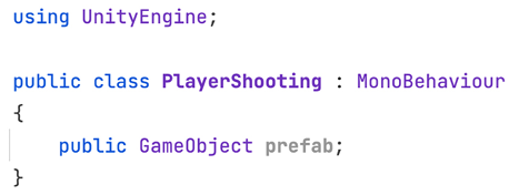
Figure 6.28: The Prefab reference field
As you might have guessed, we can use the GameObject type to not only reference Prefabs but also other objects. Imagine an enemy AI needing a reference to the player object to get its position, using GameObject to link the two objects. The trick here is considering that Prefabs are just regular GameObjects that live outside the scene; you cannot see them, but they are in memory, ready to be copied or instantiated. You will only see them through copies or instances that are placed in the scene with scripting or via the editor, as we have done so far.
- In the editor, click on the circle toward the right of the property and select the
BulletPrefab. Another option is to just drag theBulletPrefab to the property. This way, we tell our script that the bullet to shoot will be that one. Remember to drag the Prefab and not the bullet in the scene (that one should be deleted by now):

- We will shoot the bullet when the player presses the left mouse button, so place the proper if statement to handle that in the Update event function, like the one shown in the next screenshot:
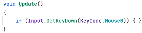
Figure 6.30: Detecting the pressure of the left mouse button
- You will notice that this time, we used GetKeyDown instead of GetKey, the former being a way to detect the exact frame the pressure of the key started; this if statement will execute its code only in that frame, and until the key is released and re-pressed, it won’t enter again. This is one way to prevent bullets from spawning in every frame, but just for fun, you can try using GetKey instead to check how it would behave. Also, KeyCode.Mouse0 is the mouse button number that belongs to left-click, KeyCode.Mouse1 is the right-click, and KeyCode.Mouse2 is the middle click.
- Use the Instantiate function to clone the Prefab, passing the reference to it as the first parameter. This will create a clone of the previously mentioned Prefab that will be placed in the scene:

Figure 6.31: Instantiating the Prefab
If you save the script and play the game, you will notice that when you press the mouse, a bullet will be spawning, but probably not in the place you are expecting. If you don’t see it, try to check the Hierarchy for new objects; it will be there. The problem here is that we didn’t specify the desired spawn position, and we have two ways of setting that, which we will see in the next steps:
- The first way is to use the
transform.positionandtransform.rotationinherited fields fromMonoBehaviour, which will tell us our current position and rotation. We can pass them as the second and third parameters of theInstantiatefunction, which will understand that this is the place we want our bullet to appear. Remember that it is important to set the rotation to make the bullet face the same direction as the player, so it will move that way:

Figure 6.32: Instantiating the Prefab in our position and rotation
- The second way is by using the previous version of
Instantiate, but saving the reference returned by the function, which will be pointing to the clone of the Prefab. This allows us to change whatever we want from it. In this case, we will need the following three lines; the first will instantiate and capture the clone reference, the second will set the position, and the third the rotation. We will also use thetransform.positionfield of the clone, but this time to change its value by using the=(assignment) operator:
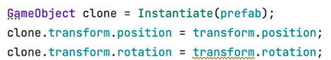
Figure 6.33: The longer version of instantiating a Prefab in a specific position
Remember that you can check the project’s GitHub repository linked in the Preface to see the full script finished. Now you can save the file with one of the versions and try to shoot.
If you try the script so far, you should see the bullet spawn in the player’s position, but in our case, it will probably be the floor. The problem here is that the player’s character pivot is there, and usually, every humanoid character has the pivot in their feet. We have several ways to fix that. The most flexible one is to create a Shoot Point, an empty GameObject child of the player, placed in the position we want the bullet to spawn. We can use the position of that object instead of the player’s position by following these steps:
- Create an empty
GameObjectin GameObject | Create Empty. Rename itShootPoint. - Make it a child of the player’s GameObject and place it where you want the bullet to appear, probably a little higher and further forward:
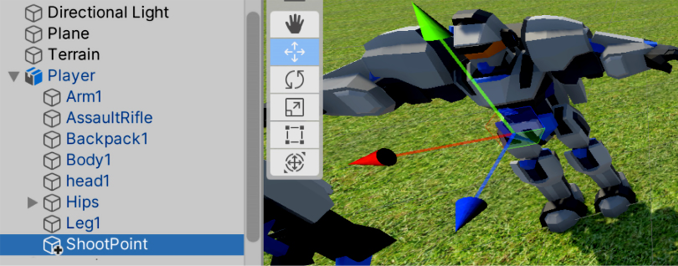
Figure 6.34: An empty ShootPoint object placed inside the character
- As usual, to access the data of another object, we need a reference to it, such as the Prefab reference, but this time it needs to point to our shoot point. We can create another
GameObjecttype field, but this time dragShootPointinstead of the Prefab. The script and the object set would look as follows:
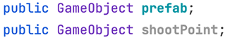
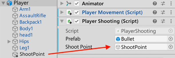
Figure 6.35: The Prefab and ShootPoint fields and how they are set in the editor
- We can access the position of the
ShootPointby using thetransform.positionfield of it again, as shown in the following screenshot:

Figure 6.36: The Prefab and ShootPoint fields and how they are set in the editor
The Visual Scripting version of ForwardMovement will look like this:
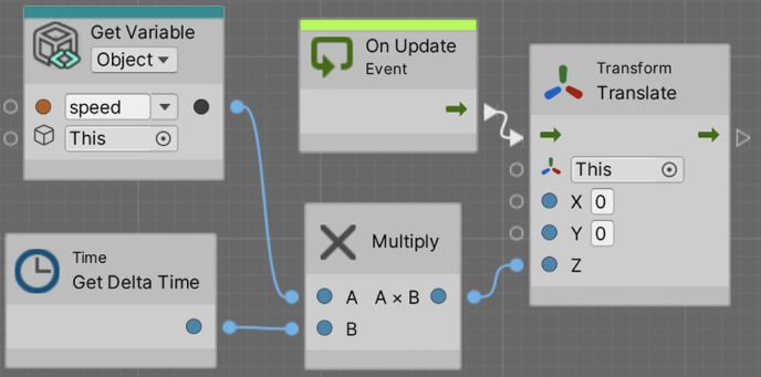
Figure 6.37: ForwardMovement with Visual Scripting
And PlayerShooting will look like this:
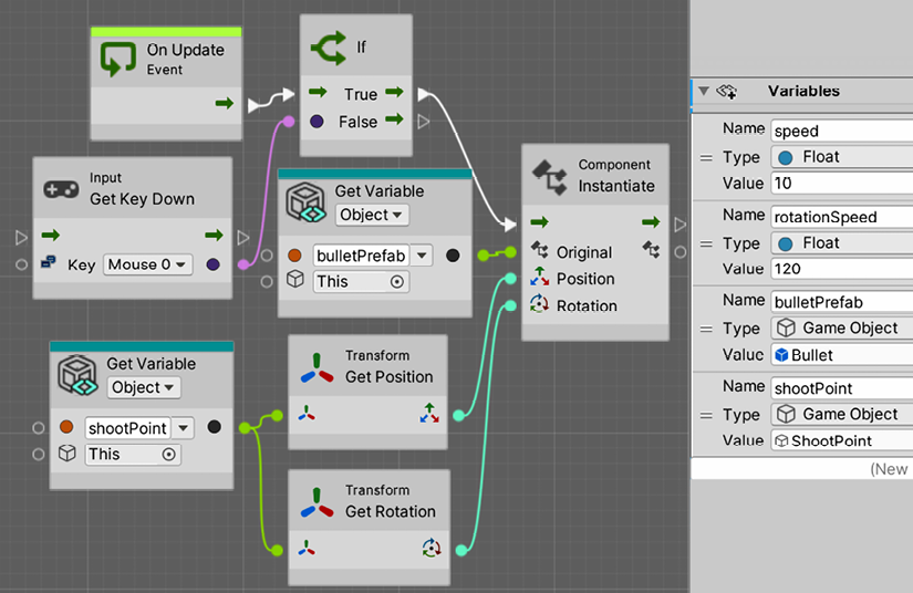
Figure 6.38: Instantiating in the PlayerShooting Visual Script
As you can see, we added a second Script Machine component with a new graph called Player Shooting. We also added a new variable, bulletPrefab, of type GameObject and dragged the Bullet Prefab to it, and a second GameObject typed variable called shootPoint, to have the reference to the bullet’s spawn position. The rest of the script is essentially the counterpart of the C# version without any major differences. Something to highlight here is how we connected the Transform GetPosition and Transform GetRotation nodes to the GetVariable node belonging to the shootPoint; in this way, we are accessing the position and rotation of the shooting point. If you don’t specify that, it will use the player’s position and rotation, which in the case of our model is in the player’s character’s feet.
You will notice that now shooting and rotating with the mouse has a problem; when moving the mouse to rotate, the pointer will fall outside the Game View, and when clicking, you will accidentally click the editor, losing the focus on the Game View, so you will need to click the Game View again to regain focus and use input again. A way to prevent this is to disable the cursor while playing. To do this, follow these steps:
- Add a
Startevent function to our Player Movement Script. - Add the two lines you can see in the following screenshot to your script. The first one will make the cursor visible, and the second one will lock it in the middle of the screen, so it will never abandon the Game View. Consider the latter; you will need to reenable the cursor when you switch back to the main menu or the pause menu, to allow the mouse to click the UI buttons:

Figure 6.39: Disabling the mouse cursor
- Save and test this. If you want to stop the game, you could either press Ctrl + Shift + P (Command + Shift + P on Mac) or press the Esc key to reenable the mouse. Both options only work in the editor; in the real game, you will need to reset
Cursor.visibletotrueandCursor.lockStatetoCursorLockMode.None. - The Visual Scripting equivalent will look like this:
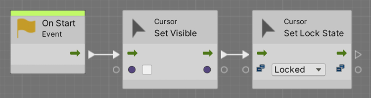
Figure 6.40: Disabling the mouse cursor in Visual Scripting
Now that we have covered the basics of object spawning, let’s see an advanced example by combining it with timers.
Timing actions
Not entirely related to spawning, but usually used together, timing actions is a common task in video games. The idea is to schedule something to happen later; maybe we want the bullet to be destroyed after a while to prevent memory overflow, or we want to control the spawn rate of enemies or when they should spawn. That’s exactly what we are going to do in this section, starting with the second, the enemy waves.
The idea is that we want to spawn enemies at a certain rate in different moments of the game; maybe we want to spawn enemies from second 1 to 5 at a rate of 2 per second, getting 10 enemies, and giving the player up to 20 seconds to finish them, programming another wave starting at 25 seconds. Of course, this depends a lot on the exact game you want, and you can start with an idea like this one and modify it after some testing to find the exact way you want the wave system to work. In our case, we will apply timing by implementing a simple wave system.
First of all, we need an enemy, and for now, we will simply use the same 3D model we used for the player, but add a Forward Movement script to simply make it move forward; later in this book, we will add AI behavior to our enemies. I suggest you try to create this Prefab by yourself and look at the following steps once you have tried it, to check the correct answer:
Drag the downloaded Character FBX model to the scene to create another instance of it, but rename it to Enemy this time:
- Add the
ForwardMovementscript created for the bullets but this time toEnemy, and set it at a speed of10for now. - Drag the
EnemyGameObject to the Project to create a Prefab based on that one; we will need to spawn it later. Remember to choose Prefab Variant, which will keep the Prefab linked with the original model to make the changes applied to the model automatically apply to the Prefab. - Remember also to destroy the original
Enemyfrom the scene.
Now, to schedule actions, we will use the Invoke functions to create timers. They are basic but enough for our requirements. Let’s use them by following these steps:
- Create an empty GameObject at one end of the base and call it
Wave1a. - Create and add a script called
WaveSpawnerto it. - Our spawner will need four fields: the
EnemyPrefabto spawn, thestartTimeof the wave, theendTime, and the spawn rate of the enemies (how much time should be between each spawn). The script and the settings will look like the following screenshot:

Figure 6.41: The fields of the wave spawner script
We will use the InvokeRepeating function to schedule a custom function to repeat periodically. You will need to schedule the repetition just once; Unity will remember that, so don’t do it every frame. This is a good reason to use the Start event function instead. The first argument of the function is a string (text between the quotation marks) with the name of the other function to execute periodically, and unlike Start or Update, you can name the function whatever you want. The second argument is the time to start repeating, our startTime field, in this case. Finally, the third argument is the repetition rate of the function—how much time needs to happen between each repetition—this being the spawnRate field. You can find how to call that function in the next screenshot, along with the custom Spawn function:

Figure 6.42: Scheduling a Spawn function to repeat
- Inside the
Spawnfunction, we can put the spawning code as we know, using theInstantiatefunction. The idea is to call this function at a certain rate to spawn one enemy per call. This time, the spawn position will be in the same position as the spawner, so place it carefully:

Figure 6.43: Instantiating in the Spawn function
If you test this script by setting the Prefab startTime and spawnRate fields to some values greater than 0, you will notice that the enemies will start spawning but never stop, and you can see that we didn’t use the endTime field so far. The idea is to call the CancelInvoke function, the one function that will cancel all the InvokeRepeating calls we made, but after a while. We will delay the execution of CancelInvoke using the Invoke function, which works similarly to InvokeRepeating, but this one executes just once. In the next screenshot, you can see how we added an Invoke call to the CancelInvoke function in Start, using the endTime field as the time to execute CancelInvoke. This will execute CancelInvoke after a while, canceling the first InvokeRepeating call that spawns the Prefab:

Figure 6.44: Scheduling a Spawn repetition but canceling after a while with CancelInvoke
This time, we used Invoke to delay the call to CancelInvoke. We didn’t create a custom function because CancelInvoke doesn’t receive arguments. If you need to schedule a function with arguments, you will need to create a wrapper function without parameters that calls the desired one and schedules it, as we did with Spawn, where the only intention is to call Instantiate with specific arguments.
- Now you can save and set some real values to our spawner. In my case, I used the ones shown in the following screenshot:

Figure 6.45: Spawning enemies from second 1 to 5 of the gameplay every 0.5 seconds, 2 per second
You should see the enemies being spawned one next to the other, and because they move forward, they will form a row of enemies. This behavior will change later with AI. Now, the Visual Scripting version will look like this:
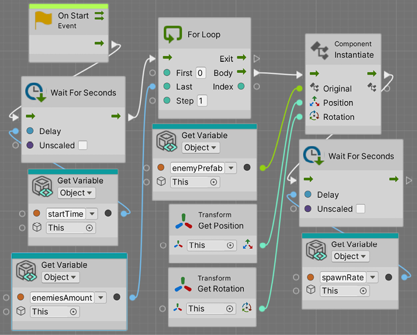
Figure 6.46: Spawning enemies in Visual Scripting
While we could use the InvokeRepeating approach in Visual Scripting, here we can see some benefits of the Visual approach, given it sometimes has more flexibility than coding. In this case, we used the Wait For Seconds node at the beginning of the Start, a node that basically will hold the execution of the flow for a couple of seconds. This will create the initial delay we had in the original script; that’s why we used the startTime as the amount of Delay.
Now, after the wait, we used a For loop; for this example, we changed the concept of the script, as we want to spawn a specific number of enemies instead of spawning during a time. The For loop is essentially a classic For that will repeat whatever is connected to the Body output pin the number of times specified by the Last input pin.
We connected that pin to a variable to control the number of enemies we want to spawn. Then, we connected an Instantiate to the Body output pin of the For loop to instantiate our enemies, and then a Wait For Seconds, to stop the flow for a time before the loop can continue spawning enemies.
Something interesting is that if you play the game now, you will receive an error in the console that will look like this:

Figure 6.47: Error when using Wait nodes
You can even go back to the graph editor and see that the conflicting node will be highlighted in red:
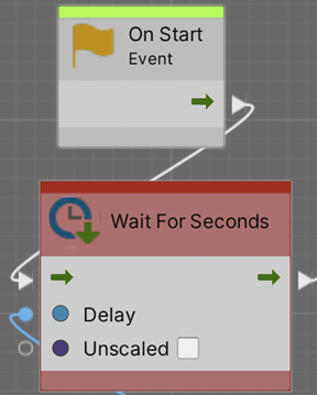
Figure 6.48: Node causing the error
The issue here is that in order for the Wait For Seconds nodes to work, you need to mark the Start event as a Coroutine. This will basically allow the event to be paused for an amount of time and be resumed later. The same concept exists in C#, but as it is simpler to implement here in Visual Scripting than in C#, we decided to go with this approach here.
To solve this error, just select the On Start event node and check the Coroutine checkbox in the Graph Inspector pane on the left of the Script Graph editor. If you don’t see it, consider clicking the Info button (circle with i) in the top-left part of the editor.
A coroutine is a function that can be paused and resumed later, and that’s exactly what the Wait node does. Coroutines also exist in MonoBehaviours, but let’s keep things simple for now.

Figure 6.49: Marking Start as a coroutine
Now that we have discussed timing and spawn, let’s discuss timing and Destroy to prevent our bullets from living forever in the memory.
Destroying objects
We can use the Destroy function to destroy object instances. The idea is to make the bullets have a script that schedules their own auto-destruction after a while to prevent them from living forever. We will create the script by following these steps:
- Select the Prefab of
Bulletand add a script calledAutodestroyto it, as you did with other objects using the Add Component > New Script option. This time, the script will be added to the Prefab, and each instance of the Prefab you spawn will have it. - You can use the
Destroyfunction, as shown in the next screenshot, to destroy the object just once inStart:
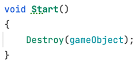
Figure 6.50: Destroying an object when it starts
The Destroy function expects the object to destroy as the first argument, and here, we are using the gameObject reference; a way to point to the GameObject our script is placed into to destroy it. If you use the this pointer instead of GameObject, we will be destroying only the Autodestroy component we are creating.
Of course, we don’t want the bullet to be destroyed as soon as it is spawned, so we need to delay the destruction. You may be thinking about using Invoke, but unlike most functions in Unity, Destroy can receive a second argument, which is the time to wait until destruction.
- Create a delay field to use as the second argument of
Destroy, as shown in the next screenshot:
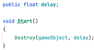
Figure 6.51: Using a field to configure the delay to destroy the object
- Set the
delayfield to a proper value; in my case, 5 was enough. Now check how the bullets despawn after a while by looking at them being removed from the Hierarchy. - The Visual Scripting equivalent will look like this:
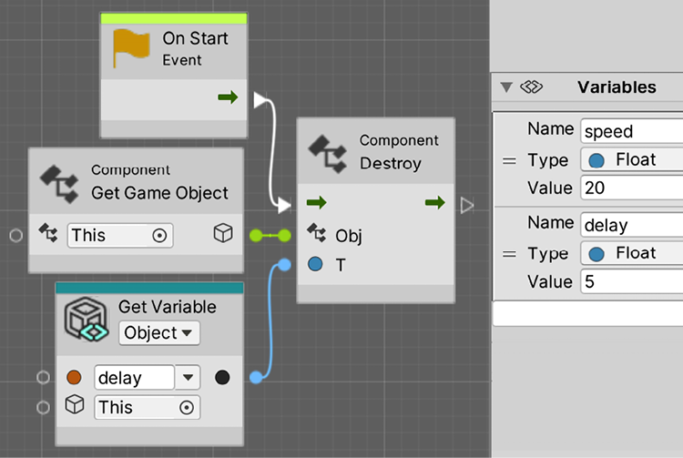
Figure 6.52: Destroying in Visual Scripting
Regarding this version, notice how we use the Component Destroy (Obj, T) version of the Destroy node, which includes the delay time.
Look for the Object Pool concept, which is a way to recycle objects instead of creating them constantly; you will learn that sometimes creating and destroying objects is not that performant.
Now, we can create and destroy objects at will, which is something very common in Unity scripting. In the next section, we will discuss how to modify the scripts we have done so far to support the new Unity Input System.
Using the new Input System
We have been using the Input class to detect the buttons and axes being pressed, and for our simple usage that is more than enough. But the default Unity input system has its limitations regarding extensibility to support new input hardware and mappings.
In this section, we will explore the following concepts:
- Installing the new Input System
- Creating Input Mappings
- Using Mappings in scripts
Let’s start exploring how to install the new Input System.
Installing the new Input System
To start using the new Input System, it needs to be installed like any other package we have installed so far, using the Package Manager. The package is just called Input System, so go ahead and install it as usual. In this case we are using version 1.4.2, but a newer one may be available when you read this chapter.
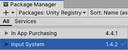
Figure 6.53: Installing the new Input System package
By default, when you install the Input System, it will prompt you to enable the new Input System with a window like the one in the following image. If that appears, just click Yes and wait for Unity to restart:

Figure 6.54: Switching the active Input System
If for some reason that didn’t appear, the other alternative is going to Edit | Project Settings and then going to Player | Other Settings | Configuration to set the Active Input Handling property to Input System Package (New).
There’s an option called Both to keep both enabled, but let’s stick with just one.

Figure 6.55: Switching the active Input System
Now that we have the system installed and set up, let’s explore how to create the Input Mappings needed.
Creating Input Mappings
The new system has a way to directly request the current state of a button or thumbstick to the gamepad, mouse, keyboard, or whatever other device we have, like what we did so far with the previous Input System. But doing so would prevent us from using one of the best features of the system, the Input Mappings.
The idea of an Input Mapping is to abstract the Input Actions from the Physical Input. Instead of thinking about the space bar, the left thumbstick of a gamepad, or the right click of a mouse, you think in terms of actions, like move, shoot, or jump. In code, you will ask if the Shoot button has been pressed, or the current value of the Move axes, like we did with the mouse axes rotatation. While the previous system supported a certain degree of Input Mapping, the one in the new Input System is way more powerful and easier to configure.
|
Action |
Mappings |
|
Shoot |
Left Mouse Button, Left Control, X button of the gamepad |
|
Jump |
Space, Y button of gamepad |
|
Horizontal Movement |
A and D keys, Left and Right arrows, gamepad Left Stick |
Figure 6.56: Example of the Input Mapping table
The power of this idea is that the actual keys or buttons that will trigger these actions are configurable in the Unity editor, allowing any game designed to alter the exact keys to control the entire game without changing the code.
We can even map more than one button to the same action, even from different devices, so we can make the mouse, keyboard, and gamepad trigger the same action, greatly simplifying our code. Another benefit is that the user can also rebind the keys with some custom UI we can add to our game, which is very common in PC games.
The easiest way to start creating an Input Mapping is through the Player Input component. This component, as the name suggests, represents the input of a particular player, allowing us to have one of those on each player in our game to support split-screen multiplayer, but let’s focus on single-player. Adding this script to our player will allow us to use the Create Actions... button to create a default Input Mapping asset. This asset, as a material, can be used by several players, so we modify it and it will affect all of them (for example, adding the Jump Input Mapping):
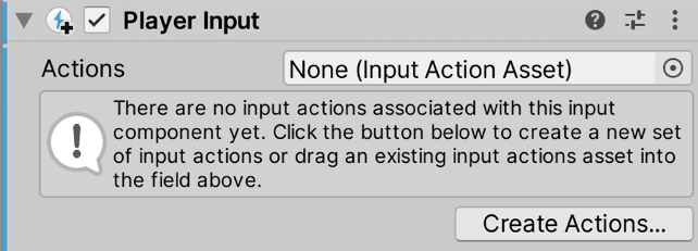
Figure 6.57: Creating Input Action assets using the Player Input component
After clicking that button and saving the asset location in the save prompt, you will see the following screen:
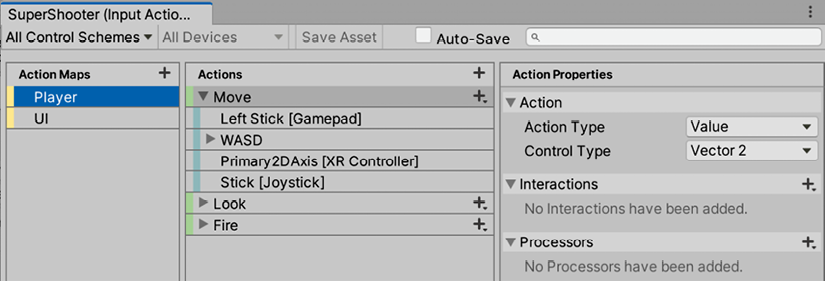
Figure 6.58: The default Input Mapping file
The first part to understand from this asset is the Action Maps section (left panel). This allows us to create separate Action Maps for different situations, for example, for driving and on-foot controls in games like GTA. By default, Player and UI mappings are created, to separate the mappings for the player controlling and navigating through the UI. If you check the Player Input component again, you will see that the Default Map property is set to Player, which means that we will only care for the player controlling the Input Mappings in this GameObject; any UI action pressed won’t be considered. We can switch the active map in runtime at will, for example, to disable the character controller input when we are in the pause menu, or switch to the driving mappings while in a car, using the same buttons but for other purposes.
If you select an Action Map in the left panel, you will see all the actions it contains in the Actions list in the middle panel. In the case of the Player, we have the Move, Look, and Fire mappings, which are exactly the inputs we will use in our game. Bear in mind you can add more if you need to use the + button, but for now, let’s stick with the default ones. When you select any action from the list, you will see their configurations in the Action Properties panel, the one on the right:

Figure 6.59: The Move (left) and Fire (right) action configurations
As you can see, there’s a property called Action Type that will dictate which kind of input we are talking about. If you select Move in the middle panel, you can see it’s a Value action type with Control Type being Vector2, meaning it will return the x and y axis values, the horizontal and vertical values—the kind we expect from any thumbstick in a gamepad. In the previous system, we got those values from separated 1D axes, like the Mouse X and Mouse Y axes, but here they are combined into a single variable for convenience. On the other hand, the Fire action is of type Button, which has the capacity not only to check its current state (pressed or released) but also do checks like if it has just been pressed or just released, the equivalents to GetKey, GetKeyDown, and GetKeyUp from the previous system.
Now that we understand which actions we have and of which type each one is, let’s discuss how the Physical Input will trigger them. You can click the arrow on the left of each action in the middle panel to see its physical mappings. Let’s start exploring the Move Action Mappings.
In this case, we have 4 mappings:
- Left Stick [Gamepad]: The left stick of the gamepad
- Primary 2D Axis [XR Controller]: The main stick of the VR controllers
- Stick [Joystick]: Main stick for arcade-like joysticks or even flight sticks
- WASD: A composite input simulating a stick through the W, A, S, and D keys
If you select any of them, you can check their configurations; let’s compare the left stick and WASD as an example:

Figure 6.60: The left stick mapping (left) and the WASD key mapping (right)
In the case of the Left Stick, you can see the Path property that allows you to pick all the possible hardware physical controls that provide Vector2 values (the x and y axes). In the case of the WASD key mapping, you can see it is a composite binding of type 2D Vector, which, as stated previously, allows us to simulate a 2D Axis with other inputs—keys in this case. If you expand the WASD Input Mappings in the middle panel, you can see all inputs that are being composited for this 2D axis, and see their configurations by selecting them:

Figure 6.61: The inputs considered for the WASD composite 2D axis
In this case, it maps not only the W, A, S, and D buttons but also the 4 keyboard arrows. Each one of those mappings has a path to select the physical button, but also the Composite Part setting, allowing us to specify which direction this input will pull the simulated stick.
And with this, we have just scratched the surface of what this system is capable of, but for now, let’s keep things simple and use these settings as they are. Remember a new asset was created with the same name as our game (SuperShooter in our case) in the root of the project. You can reopen this Action Mapping window by double-clicking it whenever you want. Now let’s see how we can use these inputs in our code.
Using Mappings in our scripts
This system provides several ways to detect the input state. The Player Input component has a Behavior property to switch between some of the available modes. The simplest one is the one called Send Messages, the one that we will use, which will execute methods in our code when the keys are pressed. In this mode, each action in the mappings will have its own event, and you can see all of them in the tooltip at the bottom of the component. As you add mappings, more will appear.

Figure 6.62: All the input events for the default mapping
From the list, we will need three, OnMove, OnLook, and OnFire. We can modify our PlayerMovement script like in the following screenshot to use them:
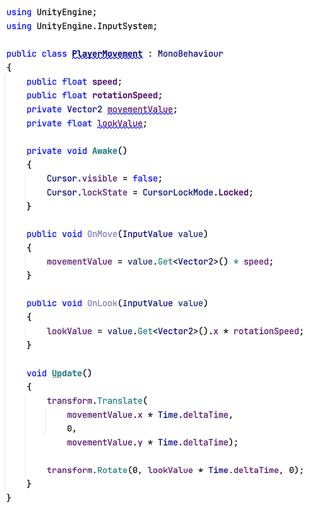
Figure 6.63: Player movement with the new Input System
The first difference you will notice is that we don’t request the status of the input in the Update method like we did before. Instead, we listen to the OnMove and OnLook events, which provide us with an InputValue parameter containing the current state of those axes. The idea is that every time these axes change value, these events will execute, and if the values didn’t change, like when the player keeps pushing the stick all the way to the right, they won’t be executed. That’s why we need to store the current value in the movementValue and lookValue variables, to use the latest value of the axis later in the Update and apply the movement in every frame. Consider those are private, meaning they won’t appear in the editor, but that’s fine for our purposes. Also, observe that we added the using UnityEngine.InputSystem line at the top of the file to enable the usage of the new Input System in our script.
In this version of the PlayerMovement script, we used the axis input type like we did with the mouse before but also for movement, unlike the previous version that used buttons. This is the preferred option most of the time, so we will stick with that version. Observe how we use a single transform.Translate to move; we need to use the x axis of movementValue to move the x axis of our player but use the y axis of movementValue to move the z axis of our player. We don’t want to move our player vertically, so that’s why we needed to split the axis this way.
The InputValue parameter has the Get<Vector2>() method, which will give us the current value of both axes, given Vector2 is a variable that contains the x and y properties. Then, we multiply the vector by the movement or rotation speed according to the case. You will notice that we don’t multiply by Time.deltaTime in the axis events, but we do that in the Update. That’s because Time.deltaTime can change between frames, so storing the movement value considering the Time.deltaTime of the last time we moved the stick won’t be useful for us. Also, notice how movementValue is a Vector2, just a combination of the x and y axes, while lookValue is a simple float. We did it this way because we will rotate our character only following the lateral movement of the mouse; we don’t want to rotate it up and down. Check that we do value.Get<Vector2>().x, with emphasis on the .x part, where we extract just the horizontal part of the axis for our calculations.
Regarding the PlayerShooting component, we need to change it to this:

Figure 6.64: PlayerShooting script using the new Input System
This case is simpler, as we don’t need to execute the shooting behavior each frame, we only need to execute something at the very same moment the input is pressed, which is exactly when the OnFire event will be executed. If you need to also detect when the key was released, you can add the InputValue parameter as we did with OnMove and OnLook, and consult the isPressed property:

Figure 6.65: Getting the state of the button
Regarding the Visual Script Machine version of our scripts, first, you will need to refresh the Visual Script Node Library by going to Edit | Project Settings | Visual Scripting and clicking the Regenerate Nodes button. If you don’t do this, you won’t see the new Input System nodes:

Figure 6.66: Regenerating Visual Scripting nodes to support the new Input System
Now, the PlayerShooting visual script would look like this:

Figure 6.67: Instantiating bullets with the new input system
The new On Input System Event Button node allows us to detect when an action button has been pressed and react accordingly. You can pick the specific action in the Input Action parameter, and you can even make the node react to the pressure, release, or hold states of the button with the option right below the node’s title. There is a bug where the Input Action property might not show any option; in such cases, try removing and adding the node again in the graph, and check that you added the ScriptMachine component to the same GameObject that has the PlayerInput component. Also check you have selected the Player GameObject in the hierarchy.
Regarding movement, it can be achieved this way:
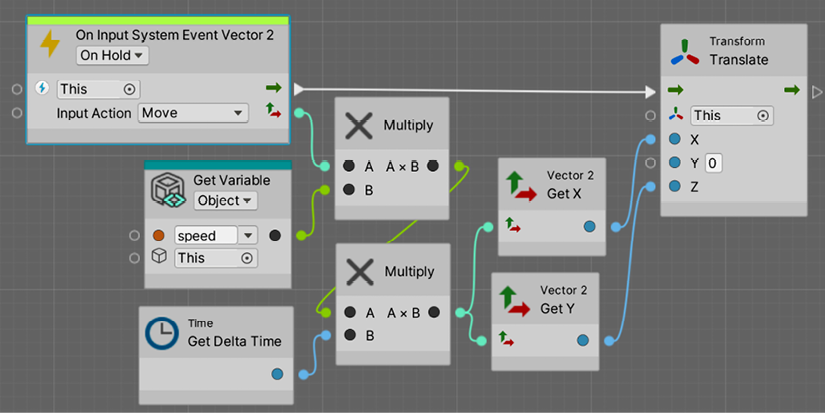
Figure 6.68: Moving with the new Input System
In this case, we used the On Input System Event Vector2 node. This time, we used the OnHold mode, which means that, unlike the C# version, it won’t execute just when the axis changes, but all the frames when the axis is pressed act like an Update; that, however, will only execute when the user is pressing the stick. The output pin of the node is the Vector2 value, so we multiply it by the speed variable (declared in the Variables component of our player) and by DeltaTime. Finally, we use the Vector2 GetX and Vector2 GetY nodes to translate over the x and z axes. You may have trouble when rewiring the Multiply nodes with the new Input System node, given the return type is different compared to the previously used node (a Vector2 instead of a single float). I recommend just deleting all nodes in this graph and redoing it to be sure everything is fine.
Summary
We created our first real scripts, which provide useful behavior. We discussed how to move a GameObject based on input and instantiate Prefabs via scripting to create objects at will according to the game situation. Also, we saw how to schedule actions, in this case, spawning, but this can be used to schedule anything. We saw how to destroy the created objects, to prevent increasing the number of objects to an unmanageable level. Finally, we explored the new Input System to provide maximum flexibility to customize our game’s input. We will be using these actions to create other kinds of objects, such as sounds and effects, later in this book.
Now you are able to create any type of movement or spawning logic your objects will need and make sure those objects are destroyed when needed. You might think that all games move and create shooting systems the same way, and while they are similar, being able to create your own movement and shooting scripts allows you to customize those aspects of the game to behave as intended and create the exact experience you are looking for.
In the next chapter, we will be discussing how to detect collisions to prevent the player and bullets from passing through walls and much more.