
CHAPTER 5
INDUCTION MACHINES
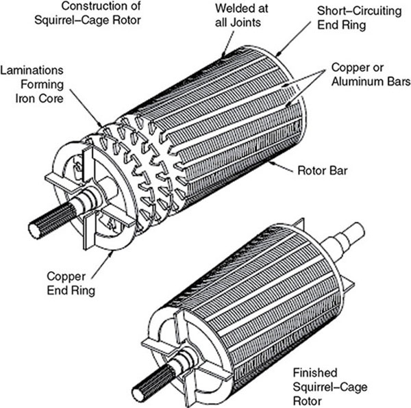
Induction machines are the most common form of electromechanical energy-conversion devices for industrial, commercial, and domestic appliances that operate at constant speed. The need for energy processing and conversion from electrical to mechanical energy to do mechanical work abounds in every sector of human endeavor. About one-third of the world's electricity consumption is used for running induction motors that drive pumps, fans, compressors, elevators, and machinery of various types to meet industrial, commercial, and domestic needs. The AC induction motor is a common form of asynchronous motor whose operation depends on three electromagnetic phenomena: The induction motor stator resembles the stator of a revolving-field, three-phase, synchronous generator. The stator or the stationary part consists of three-phase winding held in place in the slots of a laminated steel core enclosed and supported by a cast-iron steel frame, as seen in Figure 5.1 [5]. Figure 5.1 Induction motor stator. The phase windings are placed 120° electrical apart and may be externally connected in Y or delta for which six leads are brought out to a terminal box mounted on the frame of the motor. When the stator is energized from a three-phase voltage, it produces a rotating magnetic field in the stator core. Three-phase induction motors are of two kinds: Cage Rotors Cage-rotor machines (also called squirrel-cage machines) are the most common type of induction motors. In a cage-rotor design, solid conductors are in slots on the rotor. The ends of the conductors are short circuited at each end of the rotor using an “end-ring.” For small to medium-sized machines (up to a few hundred horsepower) the rotor conductors are cast using aluminum. This construction makes the rotor relatively cheap to produce. In larger machines, rotors are usually made by manually hammering solid copper bars into the rotor slots, then manually brazing an end-ring into place. Fabricated rotor cages are significantly more expensive that cast rotor cages. Figure 5.2 [5] shows a cage-rotor induction motor. Figure 5.2 Cage-rotor induction motor. Wound Rotors Wound-rotor induction machines have a three-phase winding, similar to the stator winding, on the rotor as seen in Figure 5.3 [5]. The rotor is usually Y connected with the terminals of the three rotor phases connected to slip rings. In normal operation, the windings at the slip rings are short circuited to allow currents to flow. An advantage of wound-rotor machines is that external circuits can be connected to the rotor, allowing external control of the machine. While all induction machines can be controlled to operate at different torques and speeds, wound-rotor control is particularly attractive in some applications. However, wound-rotor induction machines are usually significantly more expensive than cage rotor machines. Possible applications for wound-rotor machines include: Figure 5.3 Wound-rotor induction motor. The basic idea behind the operation of an induction machine is quite simple. The three-phase stator winding is connected to a three-phase supply. Currents flow in the stator winding, producing an mmf and flux density that rotates at synchronous speed:
The magnetic field passes conductors on the rotor and induces a voltage in those conductors. Since the conductors are short circuited, current flows in the rotor conductors, producing a second rotor magnetic field, which acts to oppose the stator magnetic field and rotates at synchronous speed. With two magnetic fields rotating at constant speed, a torque is produced. The following induction-motor concepts are important to understanding the operation and application of these machines. Leakage Reactance The leakage reactance is for magnetizing the armature of the cylindrical-rotor machines. It is given by
The mutual air-gap flux between the rotor and the stator is φ (weber, or Wb) per pole and rotates at an angular speed of ω radians per second. The flux linkage of N-turns of conductors will be at maximum when ωt = 0 and also at ωt = 90°. Assuming distributed winding, the flux linkage λa will vary as the cosine of the angle ωt. Thus, the flux linkage with coil a is
The induced voltage
where
The rms value of the generated voltage is then
In actual machines, the armature conductors are distributed in slots such that the phasor sum of the induced emf is less than the numerical sum. Hence, a factor to account for the difference is introduced, which we shall call the winding factor Kw (note that Kw varies between 0.85 and 0.95 for three-phase windings). Consequently, for distributed-phase windings, the rms value of the generated voltage is:
Let stator emf be E1 and rotor emf Er. Hence, we may write
Since Er was induced by transformer action, the induction motor behaves like a transformer with a rotating secondary winding. Hence, we may write an expression for the transformation ratio in terms of the stator and rotor parameters as:
where f is frequency in Hz, Kw1 and Kw2
are stator and rotor winding factors, Nph1 and Nph2 are the number of turns in the stator and rotor windings, and a1and a2 are the corresponding number of current paths. Suppose that the rotor circuit is open and is rotated at a speed n rpm by some external means in the duration of the rotating flux φm. If nsyn is given in rpm, the rotational speed of φm is defined as the slip s
When motor rotor is at slip s
the rotor frequency is given by
This frequency also affects the resulting voltage E′s:
If r22 is the resistance of the rotor winding in ohms/φ, with the corresponding leakage inductance L22, the wound-rotor leakage inductance in henrys/φ leads to leakage reactance of the rotor, given by:
and with slip s accounted for,
Therefore, rotor current
This mimics the transformer-equivalent circuit from the secondary side comprising of Figure 5.4 Induction-motor equivalent circuit. The primary side is equivalent to the stator-winding operating at stator frequency regardless of the slip, i.e.,
This follows from the fact that the polyphase rotor currents at slip s have a synchronous frequency and therefore produce a rotor mmf that rotates at snsync rpm relative to the rotor in the same direction as the stator flux while the rotor is rotating at a speed of (1 − s)nsyn rpm in the same direction. The resultant speed of the rotor mmf relative to the stator is the sum of those two speeds:
Synchronous speed nsyn = sn of speed of stator at stator frequency f (Hz). The ideal transformer may be used to model the equivalent circuit of an induction motor as shown in Figure 5.5. Figure 5.5 The ideal transformer model of an induction motor. Equivalent rotor resistance Example 1 A four-pole, three-phase induction motor operates from a supply whose frequency is 50 Hz. Calculate: Solution: Stator field revolves at synchronous speed, given by:
rotor speed
frequency of rotor current
at standstill
Example 2 A 110 V, 50 Hz, delta-connected induction motor has a star-connected, slip-ring rotor with phase transformation ration of 3.8. The rotor resistance and standstill leakage reactance are 0.012Ω and 0.25Ω per phase, respectively. Neglecting stator impedance and magnetizing current, determine: It should be noted that in a Δ/Y connection, primary-phase voltage is the same as line voltage. The rotor-phase voltage can be found by using the phase transformation ratio of 3.8, i.e., K = 1/3.8. Solution: Rotor-phase voltage at standstill = 1,100 × 1/3.8 = 289.5 V As shown in Figure 5.4, for an induction-machine equivalent circuit, we can compute
from which we compute
Given the value of Pin and Plosses for mechanical power
If we account for friction and stray losses (Pfw − Pstray), we have the net mechanical power as follows:
where Pfw is power lost as friction and windage. The induction motor can become a generator when I22 reverses its direction and
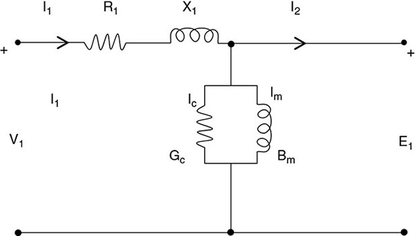
This is only possible when Q is supplied to the motor at the bus where it is connected. Assuming the machine is three-phase connected and accounting for its losses in steady-state conditions, the currents and voltages align with neutral values at the stator side. The machine's rotating air-gap flux is defined by balanced, three-phase emf of the stator. This gives a terminal voltage, which differs from the stator emf by the voltage drop in the stator leakage impedance given as
In terms of rotor emf
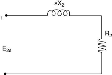
where V1 is stator terminal voltage, E1 is counter emf generated by resultant field flux, I1 is the stator current, R1 is the stator effective resistance, X1 is the stator leakage reactance. As an analog to the transformer model, we have the stator equivalent circuit as shown in Figure 5.6. Figure 5.6 Induction-motor stator equivalent circuit-transformer analog model. These quantities are included in the circuit diagram in Figure 5.6. As before, we can refer to the cage-wound rotor as a function of slip and then refer to the secondary side as seen in Figure 5.7. Figure 5.7 Rotor equivalent circuit of three-phase induction motor at slip frequency.
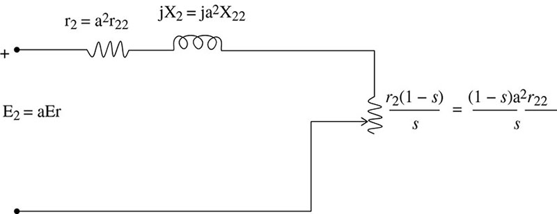
Thus, referring to the stator is essentially the same as referring the secondary quantities to the primary side of the static transformer. Earlier, we defined as part of slip
where Thus
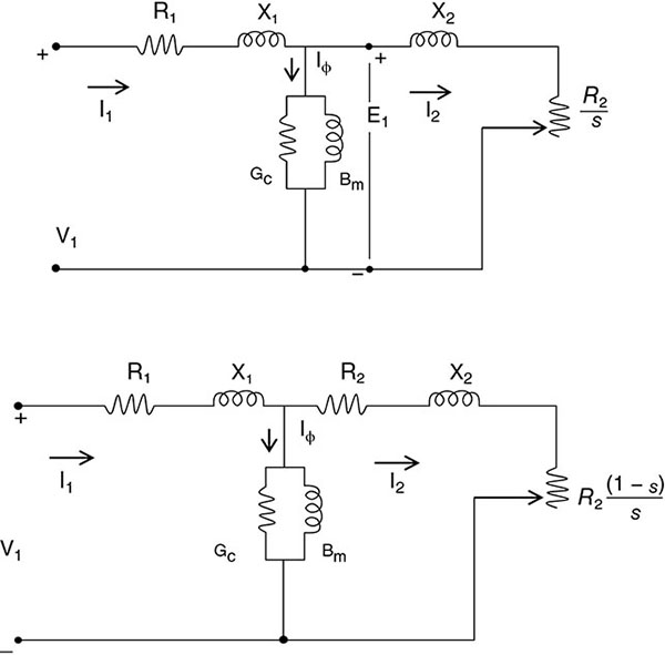
The redrawn equivalent circuits for polyphase induction motors are shown in Figure 5.8. Figure 5.8 Equivalent circuits of three-phase polyphase induction motors. The equivalent circuit is used to analyze the induction motor in general since V, I, losses, and torque are based on the model parameters. We derive them simply as follows: Pg transferred across the air gap from the stator is
The total rotor loss I2R can be written as a1I22R2. Net power is
Motor mechanical power is
Total power delivered to the rotor is a fraction of Pg(mech). (1 − s) is converted into mechanical power because of Pg1 (electrical power). The conversion (1 − s) mechanical is dissipated as rotor circuit I2R loss. The internal mechanical power per stator phase is equal to the power absorbed by the resistance
Example A 115 V, 60 Hz, three-phase, Y-connected, six-pole induction motor has an equivalent circuit consisting of stator impedance (0.07 + j0.3)Ω and an equivalent rotor impedance at standstill of (0.08 + j0.3)Ω. The magnetizing branch has Gc = 0.022 mho and Bm = 0.158 mho. Find: Solution:
where
Note that torque and power do not include stray, frictional, windage, and load losses. Example A three-phase induction motor has a four-pole, star-connected stator winding and runs on a 220 V, 50 Hz supply. The rotor resistance per phase is 0.1Ω and reactance 0.9Ω. The ratio of stator to rotor turns is 1.75. The full load slip is 5 percent. Calculate for this load: Solution: Stator voltage/phase,
Standstill rotor emf/phase,
Rotor copper loss
To approximate the model further, the exciting branch is usually neglected to allow for 30 to 50 percent full-load current and because the leakage is also higher. This is drawn as either of the two diagrams in Figure 5.9. Figure 5.9 Approximate equivalent circuit of three-phase induction motor. Example A three-phase, Y-connected, 220 V, L-L, 10Hp, 60 Hz, six-pole, induction motor has the following constants in ohms:
The total friction, windage, and core loss are assumed constant at 403 W, load slip of 2.0 percent. Determine torque, power, Istator, pf, and η of motor at rated frequency. Solution: The impedance Zf is represented in Figure 5.10 as Figure 5.10 Induction generator in self-excited mode.
Sum of
Applied voltage
Deducting losses of 403W
Efficiency
: Total stator
I2R
loss
= 3(18.8)2 × 0.294 = 312 W Friction + windage + core losses = 403W Total = 403 + 369.25 + 312 = 1,084.25W Output = 17,690
To allow for multi-application of induction motors, engineers use many options to adjust the speed of induction motors, including: The following are some applications of induction motors. The conditions under which polyphase induction machines behave as induction generators include the following. An induction generator is not a self-excited machine. In order to develop the rotating magnetic field it requires magnetizing current and reactive power. The induction generator obtains its magnetizing current and reactive power from the supply mains or from a synchronous generator connected in parallel with it. Thus, normally, the induction generator cannot work in isolation because it continuously requires reactive power from some external supply system. The only way to make an induction generator self-excited in isolated mode is to use capacitor banks for reactive power supply instead of an AC-supply system. Isolated induction generators are also known as self-excited generators. A bank of capacitors is connected across the generator's stator terminals as shown in Figure 5.10. The function of the capacitor bank is to provide the lagging reactive power to the induction generator as well as the load. So
where Q is the total lagging reactive power supplied by the capacitor bank, Q1 is the reactive power drawn by the induction generator, and Q2 is the reactive power fed to the load. The two main applications of induction generators are as follows: Solution: Solution: Principles of induction machines have been presented in this chapter. This class of electromechanical machines is important as it serves dual purposes when in an electric power system depending on its mode of excitation. We have found that, as an induction motor, it is a nonlinear load, which is of interest because of the power-quality problem of harmonic distortion it creates in an electric power system. As an induction generator, its application in wind energy systems is of importance. Consequently, irrespective of the configuration of an induction machine, its place as a load or an energy source in any power system is of utmost interest, especially in the design, operation, and management of a microgrid. Considerable resources have therefore been included in this chapter for the benefit of the student to facilitate overall knowledge of this machine in preparation for its applications in a microgrid system. Several exercises to illustrate computational modelling, performance, and speed regulation of induction machines have been presented in this chapter. A 50 kW, 440 V, 50 Hz, two-pole induction motor has a slip of 6 percent when operating at full-load conditions. At full-load conditions, the friction and windage losses are 520 W, and the core losses are 500 W. Find the following values for full-load conditions: A 480 V, 60 Hz, six-pole, three-phase, delta-connected induction motor has the following parameters: R1 = 0.461Ω, R2 = 0.258Ω, X1 = 0.507Ω, X2 = 0.309Ω, Xm = 30.74Ω, and rotational losses 2,450 W. The motor drives a mechanical load at a speed of 1,170 rpm. Calculate: A three-phase, six-pole, 10HP, 400 Hz induction motor has a slip of 3 percent at rated output power. Friction and windage losses are 300 W at rated speed. The rated condition total core losses are 350 W. R1 = R2 = 0.05Ω and X1 = X2 = 0.05Ω. Using the approximate equivalent circuit for analysis, if the motor is operating at rated output power, speed, and frequency, find: A three-phase, 50HP, 460 V, 60 Hz, 865 rpm induction motor is operating at rated conditions and has PT = 43.75 kW and I1 = 61KA. It is known that R1 = 0.15Ω and rotational losses at rated speed are 1,050 W. Determine: A 208 V, four-pole, 60 Hz, Y-connected, wound-rotor induction motor is rated at 30Hp. Its equivalent circuit components are:
For a slip of 0.05, find: The power crossing the air gap of a 60 Hz, four-pole, induction motor is 25 kW and the power converted from electrical to mechanical form in the motor is 23.2 kW. An induction motor draws 50A from a 380 V, three-phase line at a lagging power factor of 0.9. If its rotor copper losses are 1,000 W and 500 W, respectively, its core losses are 650 W, the friction and windage losses are 200 W, and the stray losses are 250 W, determine: An induction motor draws 50A from a 480 V, three-phase line at a lagging power factor of 0.85. Its stator and rotor copper losses are 1,000 W and 500 W, respectively. Its core losses are 500 W, friction and windage losses are 250 W, and stray losses are 250 W. Determine: The input to the rotor of a 208 V, three phase, 60 Hz, 24-pole induction motor is 20 kW. If the rotor current is 63.25A per phase and the rotor resistance is 0.05Ω per phase, and ignoring the rotational losses, determine:5.1 INTRODUCTION
5.2 CONSTRUCTION AND TYPES OF INDUCTION MOTORS


5.3 OPERATING PRINCIPLE
![]()
5.4 BASIC INDUCTION-MOTOR CONCEPTS
![]()
![]()
![]()
![]()
![]()

![]()
![]()
![]()
![]()

5.5 INDUCTION-MOTOR SLIP
![]()
![]()
![]()
![]()
5.6 ROTOR CURRENT AND LEAKAGE REACTANCE
![]()
![]()

![]() in series with the reactance of the secondary side given as the equivalent circuit, as shown in Figure 5.4.
in series with the reactance of the secondary side given as the equivalent circuit, as shown in Figure 5.4.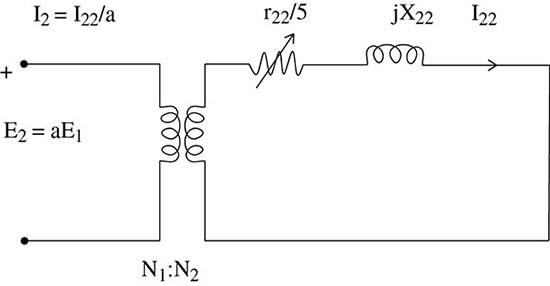
![]()
![]()
![]() is shown in two parts, namely:
is shown in two parts, namely:
![]() .
.
![]()
![]()
![]()
![]()
![]()
![]()
![]()
5.7 ROTOR COPPER LOSS
![]()
![]()
![]()
![]()
![]()
![]()
5.8 DEVELOPING THE EQUIVALENT CIRCUIT OF POLYPHASE, WOUND-ROTOR INDUCTION MOTORS
![]()
![]()
![]()
![]()

![]()
![]()
![]()
![]()
![]()
![]()
![]()
![]()
![]()
![]()
![]()
Actual rotor speed N = (1 − s)Ns = (1 − 0.02) × 1, 200 = 1, 176 rpm
Therefore, ![]() .
.![]()
![]()
5.9 COMPUTING CORRESPONDING TORQUE OF INDUCTION MOTORS
![]()
![]()
![]()
![]()
![]()
![]()
![]()
![]()
![]()
5.10 APPROXIMATION MODEL FOR INDUCTION MACHINES

![]()

![]()
![]()
![]()
![]()
![]()
![]()
![]()
![]()
![]()
![]()
![]()
![]()
![]()
![]()
![]()
![]()
![]()
![]()
![]()
![]()
![]()
![]()

![]()
![]()
5.11 SPEED CONTROL OF INDUCTION MOTORS
5.12 APPLICATION OF INDUCTION MOTORS
5.13 INDUCTION-GENERATOR PRINCIPLES
5.13.1 Isolated Induction Generators
![]()
5.13.2 Application of Induction Generators
Illustrative Problems and Examples

= 0.01735 × 60
= 1.041 Hz
![]()
5.14 CHAPTER SUMMARY
EXERCISES
R1 = 0.100Ω
R2 = 0.070Ω
Xm = 10.0Ω
X1 = 0.210Ω
X2 = 0.210Ω
Pmech = 500W
Pcore = 400W
BIBLIOGRAPHY