
Having understood the business patterns described in Chapter 1, Basic Principles, and the structure of the blueprint covered in Chapter 3, Integration Architecture Blueprint, this chapter will use individual scenarios to illustrate how the business pattern can be implemented using the Integration Architecture Blueprint.
Note
The scenarios have been deliberately designed to be independent of specific vendor products, and are based solely on the building blocks that form part of the different layers of the blueprint.
The symbols used have the same semantic meaning as described in Chapter 3.
This chapter will:
- Explain service-oriented integration scenarios
- Use scenarios to show how data integration business patterns can be implemented
- Present a description of scenarios for implementing the business patterns for EAI/EII integration
- Look in detail at the implementation of event processing business patterns
- Describe a scenario for implementing business patterns for grid computing and Extreme Transaction Processing (XTP)
- Explain how an SAP ERP system can be combined with the integration blueprint
- Explain how an existing integration solution can be modernized using SOA, and describe a scenario that has already been implemented in practice
- Combine the integration blueprint with the other Trivadis Architecture Blueprints
These scenarios show how the EAI/EII integration business patterns described in Chapter 1 can be implemented. These business patterns are as follows:
- Direct connection: Represents the simplest type of interaction between two applications and is based on a 1:1 topology, in other words, an individual point-to-point connection.
- Broker: Is based on the direct connection pattern and extends it to a 1: N topology. It allows an individual query from a source application to be routed to several target applications.
- Router: A variant of the broker pattern with several potential target applications, where the message is routed to only one target application.
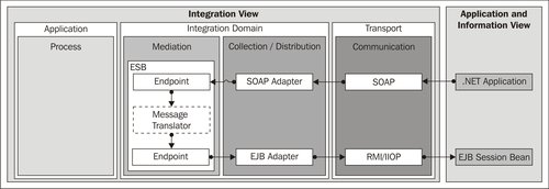
An SOA-based implementation of the direct connection business pattern makes use of an ESB component in the mediation layer, as shown in the following diagram:
Trigger:
Primary flow:
Alternative flows:
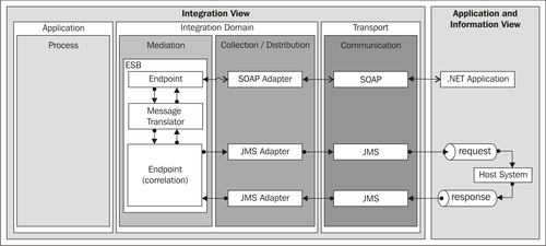
A variant of the previous scenario is that of bridging from a synchronous to an asynchronous request and response exchange pattern. This can be helpful if the target system is only accessible through some message-oriented middleware (MOM), that is, a message queue. Asynchronous request-response messaging can be achieved using separate queues: one for the request messages and one for the response messages. Asynchronous request-response messaging is often the best approach for interacting with some mainframe systems, such as IBM zSeries systems through MQSeries. (IBM's message-oriented middleware offering, now also known as Websphere MQ.)
Trigger:
- An application sends a request using a web service.
Primary flow:
- An endpoint on the ESB receives the request through SOAP from the calling application.
- The message is translated into the format of the target system.
- The message is placed into the request queue through a JMS adapter, adding some additional information used for correlation.
- The host system consumes the request message from the queue, processes the request, and sends the response information by placing the message into the response queue, together with the correlation information.
- The ESB endpoint consumes the response message and uses the correlation information to correlate the response with the corresponding request.
- The response is translated into the source format and returned as an SOAP response message to the requester.
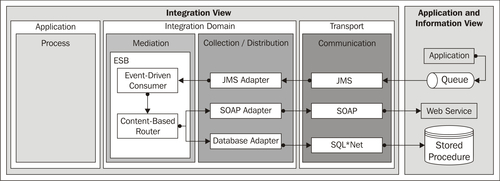
An SOA-based implementation of the broker business pattern also makes use of an ESB in the mediation layer. This provides support for a publish/subscribe pattern, or a message dispatcher pattern. The scenario is shown in the following diagram:
Trigger:
- An application places a message in the queue.
Primary flow:
- An event-driven consumer building block on the ESB uses the JMS adapter to extract the message from the queue and sends it in a channel on the bus.
- The message is forwarded by a content-based router building block to the interested systems (there may be more than one). The router bases its activities on the content of the message, in other words, the information in the message header or body.
- The first system offers a web service interface and can therefore be connected directly through an SOAP adapter.
- The second system is connected to the database by means of a stored procedure, which is supported by the corresponding database adapter.
Alternative flows:
- The message router can be based on the canonical data model, which means that a message translator building block is incorporated upstream and downstream of the message router building block. First of all, the message is converted into canonical format, then the routing logic is applied to the canonical format, and the message is transformed into the format of the target system before it is forwarded.
- If the routing rules are complex, they can be externalized into an external rule engine.
- The content-based router can be replaced by a dynamic router, which results in a dynamic subscribe mechanism that allows the potential target systems to subscribe dynamically.
- BPEL can be used for the mediation instead of the ESB.
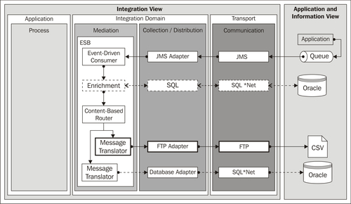
An SOA-based implementation of the router business pattern is possible if an ESB is used in the mediation layer. This is shown in the following diagram:
Trigger:
Primary flow:
- An event-driven consumer building block on the ESB removes the message from the queue through the JMS adapter and places it in a channel on the bus.
- A content-based router identifies, based on the content of the message, one target system, which in this case is either the FTP or Database distributor (for this example, FTP is chosen, which is marked in bold).
- The message is transformed into the necessary target format by a message translator building block.
- An FTP adapter writes the message to a file (CSV format) and forwards it to the receiver using the FTP protocol.
Alternative flows:
- The message translator is not needed if the target format is the same as that of the message that triggers the process
- If the routing rules are complex, they can be externalized into an external rule engine
- BPEL can be used for the mediation instead of the ESB