
This chapter describes the Trivadis Integration Architecture Blueprint and its components. It will:
- Cover the information flow and the mutual dependencies between the components of the blueprint
- Define the communication layer, which is part of the integration domain level
- Contain a description of the collection/distribution layer, which forms part of the integration domain level
- Explain the mediation layer, which belongs to the integration domain level
- Describe the process layer, which is a component of the application level
- Cover notation and visualization, which contains information about tools for integration architects
The Trivadis Integration Architecture Blueprint specifies the building blocks needed for the effective implementation of integration solutions. It ensures consistent quality in the implementation of integration strategies as a result of a simple, tried-and-tested structure, and the use of familiar integration patterns (Hohpe, Wolf 2004).
The Trivadis Integration Architecture Blueprint uses common standardized techniques, components, and patterns, and is based on the layered architecture principle.
A layered architecture divides the overall architecture into different layers with different responsibilities. Depending on the size of the system and the problem involved, each layer can be broken down into further layers. Layers represent a logical construct, and can be distributed across one or more physical tiers. In contrast to levels, layers are organized hierarchically, and different layers can be located on the same level. Within the individual layers, the building blocks can be strongly cohesive. Extensive decoupling is needed between the layers. The rule is that higher-level layers can only be dependent on the layers beneath them and not vice versa. Each building block in a layer is only dependent on building blocks in the same layer, or the layers beneath. It is essential to create a layer structure that isolates the most important cohesive design aspects from one another, so that the building blocks within the layers are decoupled.
The blueprint is process oriented, and its notation and structure are determined by the blueprint's dependencies and information flow in the integration process. An explanation of how the individual layers, their building blocks, and tasks can be identified from the requirements of the information flow is given on the basis of a simple scenario. In this scenario, the information is transported from one source to another target system using an integration solution.
In the blueprint, the building blocks and scenarios are described using familiar design patterns from different sources:
- (Hohpe, Wolf 2004)
- (Adams et al. 2001)
- (Coral8 2007)
- (Russel et al. 2006)
These patterns are used in a shared context on different layers. The Trivadis Integration Architecture Blueprint includes only the integration-related parts of the overall architecture, and describes the specific view of the technical integration domain in an overall architecture. It focuses on the information flow between systems in the context of domain-driven design.
Domain-driven design is a means of communication, which is based on a profound understanding of the relevant business domain. This is subsequently modeled specifically for the application in question. Domain models contain no technical considerations and are restricted exclusively to business aspects. Domain models represent an abstraction of a business domain, which aims to capture the exemplary aspects of a specific implementation for this domain. The objectives are:
- To significantly simplify communication between domain experts and developers by using a common language (the domain model)
- To enable the requirements placed on the software to be defined more accurately and in a more targeted way
- It must be possible to describe, specify, and document the software more precisely and more comprehensibly, using a clearly defined language, which will make it easier to maintain
The technical aspects of architecture can be grouped into domains in order to create specific views of the overall system. These domains cover security, performance, and other areas. The integration of systems and information also represents a specific view of the overall system, and can be turned into a domain.
Integration domain is used to mean different things in different contexts. One widely used meaning is "application domain," in other words, a clearly defined, everyday problem area where computer systems and software are used. Enterprise architectures are often divided into business and technical domains:
The blueprint, however, sees integration as a technical domain, which supports business domains, and has its own views that can be regarded as complementary to the views of other architecture descriptions.
In accordance with Evans (Evans, 2004), the Trivadis Integration Architecture Blueprint is a ubiquitous language for describing integration systems. This and the structure of the integration domain on which it is based, have been tried and tested in a variety of integration projects using different technologies and products. The blueprint has demonstrated that it offers an easy-to-use method for structuring and documenting implementation solutions. As domain models for integration can be formulated differently depending on the target platform (for example, an object-oriented system or a classic ETL solution), the domain model is not described in terms of object orientation. Instead, the necessary functionality takes the form of building blocks (which are often identical with familiar design patterns) on a higher level of abstraction. This makes it possible to use the blueprint in a heterogeneous development environment with profitable results.
An architecture blueprint is based on widely used, tried-and-tested techniques, components, and patterns, which are grouped into a suitable structure to meet the requirements of the target domain.
The concepts, the functionality, and the building blocks to be implemented are described in an abstract form in blueprints. These are then replaced or fine-tuned by product-specific building blocks in the implementation project. Therefore, the Trivadis Integration Architecture Blueprint has been deliberately designed to be independent of individual vendors, products, and technologies. It includes integration scenarios and proposals that apply to specific problems, and can be used as aids during the project implementation process. The standardized view of the integration domain and the standardized means of representation enable strategies, concepts, solutions, and products to be compared with one another more easily in evaluations of architectures.
The specifications of the blueprint act as guidelines. Differences between this model and reality may well occur when the blueprint is implemented in a specific project. Individual building blocks and the relationships between them may not be needed, or may be grouped together. For example, the adapter and mapper building blocks may be joined together to form one component in implementation processes or products.
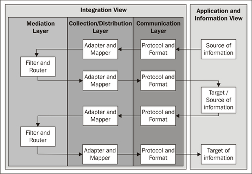
The following diagram is an overview of the Trivadis Integration Architecture Blueprint. It makes a distinction between the application and information view and the integration view.

The application and information view consists of external systems, which are to be connected together by an integration solution. These are source or target entities in the information flow of an integration solution. Generally one physical system can also take on both roles. The building blocks belonging to the view, and the view itself, must be regarded as external to the integration system that is being described and, therefore, not the subject of the integration blueprint. The external systems can be divided into three main categories:
- Transactional information storage: This includes classic relational database management systems (RDBMS) and messaging systems (queues, topics). The focus is on data integration.
- Non-transactional information storage: This is primarily file-based systems and non-relational data stores (NoSQL) with a focus on data integration.
- Applications: Applications include transactional or non-transactional systems that are being integrated (ERP—Enterprise Resource Planning, CMS—Content Management System, and so on) and can be accessed through a standardized API (web service, RMI/IIOP, DCOM, and so on). The focus is on application and process integration.
The integration view lies at the heart of the integration blueprint and is divided (on the basis of the principle of divide and conquer) into the following levels:
- Transport level: The transport level encapsulates the technical details of communication protocols and formats for the external systems. It contains:
- Communication layer: The communication layer is part of the transport level, and is responsible for transporting information. This layer links the integration solution with external systems, and represents a type of gateway to the infrastructure at an architectural level. It consists of transport protocols and formats.
- Integration domain level: The integration domain level covers the classic areas of integration, including typical elements of the integration domain, such as adapters, routers, and filters. It is divided into:
- Collection/distribution layer: This layer is responsible for connecting components. It is completely separate from the main part of the integration domain (mediation). The building blocks in this layer connect the mediation layer above with the communication layer below. The layer is responsible for encapsulating external protocols and their technical details from the integration application, and transforming external technical formats into familiar internal technical formats.
- Mediation layer: This layer is responsible for forwarding information. Its main task is to ensure the reliable forwarding of information to business components in the process layer, or directly to output channels that are assigned to the collection/distribution layer, and that distribute data to the target systems. This is the most important functionality of the integration domain. In more complex scenarios, the information forwarding process can be enhanced by information transformation, filtering, and so on.
- Application level: The application level encapsulates the integration management and process logic. It is an optional level and contains:
- Process layer: The process layer is part of the application level, and is responsible for orchestrating component and service calls. It manages the integration processes by controlling the building blocks in the mediation layer (if they cannot act autonomously).
The integration view contains additional functionality that cannot be assigned to any of the levels and layers referred to above. This functionality consists of so-called cross-cutting concerns that can be used by building blocks from several other layers. Cross-cutting concerns include:
- Assembly/deployment: Contains configurations (often declarative or scripted) of the components and services. For example, this is where the versioning of Open Service Gateway initiative (OSGi) services is specified.
- Transaction: Provides the transaction infrastructure used by the building blocks in the integration domain.
- Security/management: This is the security and management infrastructure used by the building blocks in the integration domain. It includes, for example, libraries with security functionality, JMX agents, and similar entities.
- Monitoring, BAM, QoS: These components are used for monitoring operations. This includes ensuring compliance with the defined Service Level Agreements (SLA) and Quality of Service (QoS). Business Activity Monitoring (BAM) products can be used for monitoring purposes.
- Governance: These components and artifacts form the basis for SLAs and QoS. The artifacts include business regulations, for example. In addition, this is where responsibilities, functional and non-functional requirements, and accounting rules for the services/capacities used are defined.
The Trivadis Integration Architecture Blueprint connects applications and systems together with its levels and layers. From an integration perspective, the application/ system is responsible for providing and storing information (application and information view). The tasks of the integration solution include transporting information from the source systems, together with collecting, transforming, filtering, forwarding, and distributing information, and transporting it to the target systems. These tasks can only be performed efficiently if the integration view has a logical structure. It must be possible for the tasks to be distributed across different layers in order to give improved decoupling.
- Transporting
- Connecting
- Forwarding
These tasks result in the creation of communication, collection, mediation, and distribution layers. Each layer has a specific role to ensure that it covers the responsibilities and related tasks. These roles are that of a transporter, collector, mediator, and distributor. The information flow in an integration solution determines the call sequence for the building blocks. It is advisable to combine the collection and distribution layers to form a single layer, as both of these layers perform their tasks—collecting and distributing data—using the same building blocks. In the architecture blueprint this layer is referred to as the collection/distribution layer. The result of introducing this layer is that the source and target systems are on the same level from the perspective of the integration solution. As a consequence, the direction of the information flow changes.
The integration solution consists of the mediation (forwarding), collection/distribution (connecting), and communication (transporting) layers. The mediation layer requires additional building blocks that control the integration process, as it can seldom act independently or passively. The orchestrator manages the information flow, working together with the job scheduler or workflow building blocks.
The integration blueprint is therefore divided into the following four layers:
- Process
- Mediation
- Collection/distribution
- Communication
The allocation of the various layers of the Trivadis Integration Architecture Blueprint to the three levels application, integration domain, and transport enables an integration solution to be embedded in an overall architecture. From an application perspective, the management of the information flow as a business process is essential, while standardized and reliable communication is important for the technical infrastructure. In contrast to other common approaches to integration, the integration blueprint is the central component of an overall solution. As a result, the integration architecture is always considered, designed, specified, implemented, and operated as part of the design process for applications and systems.
In simple cases, a single integration process consists of a source system, which reads information from an integration solution and a target system, to which information from the integration solution is written, as shown in the following diagram:

A distinction is made between two different views as follows:
- The application and information view consists of external systems, which are to be connected together using an integration solution. These are source or target entities in the information flow. Generally one physical system can also take on both roles. The external systems can be divided into three main categories: transactional information storage, non-transactional information storage, and applications.
- The integration view lies at the heart of the integration architecture blueprint.
The tasks and the building blocks of the two views are described in the following table:
|
View |
Building block |
Task |
|---|---|---|
|
Application and Information |
Source system Target system |
Providing information Storing information |
|
Integration |
Integration solution |
Collecting information from the sources, transporting data using external infrastructure components, transforming and forwarding information, and distributing it to target systems |
Source and target systems frequently use different information formats. As a result, the integration solution must be able to process both formats and transform data from one format to another. In the preceding diagram, the information is converted from the S (source) into the T (target) format, or from the diamond to the circle format. The more systems and formats that are involved in an integration process, the more comprehensive and complex the transformation logic is. Adaptations to other systems at a later stage are often complicated and costly.
The tasks of the integration view include:
- Transporting information (communication layer) from the source systems
- Assembling information (collection layer)
- Transforming, filtering, and forwarding (mediation layer)
- Distributing information (distribution layer),
- Transporting information (communication layer) to the target systems.
This results in the creation of layers, as shown the following diagram:

The diagram shows the layers without the optional process layer. In the case of simple information flows, this layer can be omitted. It will be described in a later section.
The division of the integration view into different layers allows for improved decoupling through the Separation of Concerns (SoC) and the break down into the following three goals:
- Transporting: The communication layer transports the information using the appropriate communication protocols.
- Connecting: The collection layer collects the data from the transport building blocks and forwards it to the building blocks of the mediation layer. The distribution layer distributes the data to the transport building blocks and collects it from the mediation layer.
- Forwarding: The mediation layer has the goal of forwarding information to the correct building block in the distribution layer. It receives the information from the collection layer.
Each layer has a specific role to ensure that the target systems and the related tasks are covered. The resulting roles are transporter, collector, mediator, and distributor.
Tip
Defining a mediator pattern
A mediator is a software design pattern which belongs to the group of behavioral patterns, because it can influence the running behavior of a program. The pattern is used to manage the cooperative behavior of objects. However, the objects do not cooperate directly with one another, but using a mediator.
The mediator provides a standardized interface to replace a series of interfaces belonging to a subsystem.
The use of a mediator brings the following range of benefits:
The addition of roles to the layer diagram enables the identification of the building blocks which achieve the goals and objectives of the integration layers.
The information flow between the source and the target system, the roles of the individual layers, and the formats used are shown in the next diagram:

The following table describes the roles in detail
|
Layer |
Role |
Description |
|---|---|---|
|
Communication |
Transporter |
Transports the information from the source systems to the integration solution or to the adapter building block in the collection layer. The information format is that of the source system. In other words, if a table is accessed, as in this example, through Java Database Connectivity (JDBC) API and SQL, the format is that of an SQL result set. |
|
Collection |
Collector |
The collector connects the integration solution to the network building block in the communication layer, and can convert the data from the transport format to an internal technical format. In the example, the SQL result set is converted into a Java object. |
|
Mediation |
Mediator |
The mediator waits actively (polling) or passively (event-driven) for information and forwards it to one or more potential distributors. The source format can first be transformed into a canonical data format (corresponding to the canonical data model pattern) in order for the forwarding to remain independent of the source system. In the example, before the routing, the data is converted from the source format (S diamond) to the canonical format (C rhombus). After the routing process, but before the data is forwarded to the distributor, it is converted into the target format (T circle). |
|
Distribution |
Distributor |
The distributor connects the integration solution to the network building block in the communication layer for the target solution. It converts the data from the internal technical format to the transport format. If the target system format is a file, as in the example, the Java object is transformed into a file. |
|
Communication |
Transporter |
Transports the information from the integration solution to the target systems. In this example, a file is sent using the File Transfer Protocol (FTP). |
The roles of collector, mediator, and distributor describe the tasks involved in a very general form. In practice, it is advisable to break down the roles even further and assign appropriate building blocks to them. The following diagram shows the allocation of different building blocks to the mediation, collection, and distribution layers and their roles:

These building blocks are run through one after another, corresponding to the information flow.
The collector role in the collection layer is performed by the following building blocks:
The mediator role in the mediation layer is performed by the following building blocks:
- Message translator: converts the internal format into the canonical format on the basis of the canonical data model.
- Router: determines the target, in other words, the system that the data will be forwarded to, possibly using the information in the canonical format.
- Message translator: converts the canonical format into an internal target format.
The distributor role in the distribution layer is allocated to the following building blocks:
It is advisable to combine the collection and distribution layers to form a single layer, as both of these layers perform their tasks—collecting and distributing data—using the same building blocks. In the architecture blueprint, this layer is referred to as the collection/distribution layer.
This changes the representation of the layers and the information flow, as shown in the following diagram:

Collection and distribution have been combined to form one layer. There is only one occurrence of the communication layer and of the Application and Information View. The direction of the information flow also changes. It no longer passes through the layers from left to right. Instead it moves from top right via the mediation layer, and back to bottom right.
The representation of the roles in the image below shows the change in the information flow, which now moves from the source system in the top-right corner, through the mediation layer to the target systems in the bottom-right corner.

However, the sequence and the functionality of the building blocks and formats remain the same. Only the number of layers and the direction of the information flow change.

The integration solution consists of the mediation (forwarding), collection/distribution (connecting), and communication (transporting) layers. The mediation layer requires additional building blocks that control the integration process, as it can seldom act independently or passively. This is only the case when it is driven by external events or functions as a polling consumer. In all other cases it must be managed, and this role is fulfilled by the orchestrator in the process layer.
The most important purpose of the process layer is to orchestrate the information flow, as shown in the following diagram:

Tip
Orchestrating
Orchestrating involves controlling and managing the building blocks in the mediation layer below. In a simple case, this task can be performed by a job-scheduling building block that triggers an integration process. In an SOA environment, BPEL (Business Process Execution Language) can be used to implement entire integration processes which are also allocated to this layer, and which orchestrate building blocks from the mediation layer.
Adding the process layer to the information flow, as shown in the following image, results in an additional orchestrator role which must be performed by a specific building block:

In this case, the orchestrator controls the mediation layer and can therefore start the integration or the information flow, for example. The mediator and the building blocks which implement the mediator functionality become passive entities that are initiated by the process layer.
In practice, the role of the orchestrator is, of course, further concretized by using specific building blocks. For example, the tasks of the orchestrator can be carried out by a job-scheduler building block, as shown in this modified diagram:

However, the orchestrator in the process layer can also be activated or triggered by a source system, as demonstrated in the following diagram. In this case, the orchestrator role is fulfilled by a workflow or BPEL building block, and by that, implements an integration process.

A query or message from an information source initiates the integration process via protocol and format, and through filter and router building blocks. The process is executed autonomously and uses an additional filter and router building block to initiate the target systems.
All the previous examples show a single information flow in a simple integration. However, the layer structure must also function in more complex information flows. The following examples illustrate this.
The target system in the first information flow becomes the source system of the subsequent information flow, as shown in the following diagram:
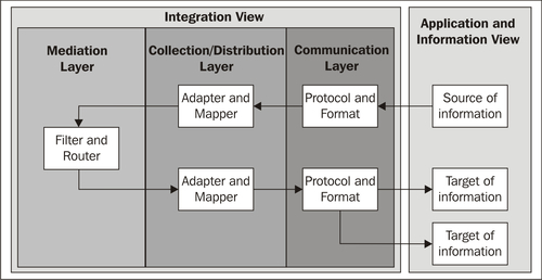
More complex information flows may have several information target systems. In the example in the following diagram, the information is distributed in the mediation layer using the router building block.

The routing to different target systems can also take place in the communication layer. In the example shown in the following diagram, the information is distributed in the communication layer using publish/subscribe or multicast protocols.
A layer can share its tasks among several building blocks, which run one after another, as demonstrated in the following diagram. The mediation layer first uses a translator building block to convert the message to a canonical format, then enhances the information using an enrichment building block, and finally forwards the information to the correct target system.

The process layer can be used to manage more complex integration solutions, by implementing a process-driven integration. One example of the use of a workflow building block is shown in the following diagram:

The workflow building block implements an integration process in a flexible way, and is started by a source system. The individual steps in the workflow integrate further systems. In step 1 the information is fetched from one source system, and in step 2 a direct link is established to a target system without using a building block in the mediation layer. Step 3 links in another target system, but in this case the distribution process is delegated to the mediation layer and a router building block.
A glance at the previous examples shows that the integration process and its implementation take place on three different levels:
- The communication layer: This layer encapsulates building blocks made available by the infrastructure.
- The mediation and collection/distribution layers: These layers are responsible for integrating two or more systems. They are concerned solely with integration, and the implemented logic can be assigned completely to the integration domain.
- The process layer: This layer is optional and is used when an additional external component is needed for managing and controlling the integration process. The implemented logic cannot be assigned exclusively to the integration domain. Application-specific business logic may also be used in implementing business processes.

The blueprint allows for this by assigning the four layers shown above to the following three levels:
- Transport level: This level contains the building blocks made available by the relevant infrastructure.
- Integration domain level: This level contains building blocks that implement the integration.
- Application level: This level contains building blocks that implement both integration and application tasks.
This last addition of the levels completes the integration blueprint and leads to the overview diagram, which is repeated here:

The allocation of the various layers of the Trivadis Integration Architecture Blueprint to the application, integration domain, and transport levels, enables an integration solution to be embedded in an overall architecture. From an application perspective, the management of the information flow as a business process is essential, while standardized and reliable communication is important for the technical infrastructure.