
17
Creating Animations with Animator, Cinemachine, and Timeline
Sometimes, we need to move objects in a predetermined way, such as with cutscenes, or specific character animations, such as jumping, running, and so on. In this chapter, we will go over several Unity animation systems to create all the possible movements of objects we can get without scripting.
In this chapter, we will examine the following animation concepts:
- Using Skinning Animation with Animator
- Scripting animations
- Creating dynamic cameras with Cinemachine
- Creating cutscenes with Timeline
By the end of this chapter, you will be able to create cutscenes to tell the history of your game or highlight specific areas of your level, as well as create dynamic cameras that are capable of giving an accurate look to your game, regardless of the situation.
Using Skinning Animation with Animator
So far, we have used what are called static meshes, which are solid three-dimensional models that are not supposed to bend or animate in any way (aside from moving separately, like the doors of a car).
We also have another kind of mesh, called skinned meshes, which are meshes that have the ability to bend based on a skeleton, so they can emulate the muscle movements of the human body. We are going to explore how to integrate animated humanoid characters into our project to create enemy and player movements.
In this section, we will examine the following skeletal mesh concepts:
- Understanding skinning
- Importing skinned meshes
- Integration using Animator Controllers
- Using Avatar Masks
We are going to explore the concept of skinning and how it allows you to animate characters. Then, we are going to bring animated meshes into our project to finally apply animations to them. Let’s start by discussing how to bring skeletal animations into our project.
Understanding skinning
In order to get an animated mesh, we need to have four pieces, starting with the mesh that will be animated, which is created the same way as any other mesh. Then, we need the skeleton, which is a set of bones that will match the desired mesh topology, such as the arms, fingers, feet, and so on. In Figure 17.1, you can see an example of a set of bones aligned with our target mesh:

Figure 17.1: A ninja mesh with a skeleton matching its default pose
Once the artist has created the model and its bones, the next step is to do skinning, which is the act of associating every vertex of the model to one or more bones. This way, when you move a bone, the associated vertices will move with it. In Figure 17.2, you can see the triangles of a mesh being painted according to the color of the bone that affects it as a way to visualize the influence of the bones. You will notice blending between colors, meaning that those vertexes are affected differently by different bones to allow the vertexes near an articulation to bend nicely. Also, Figure 17.2 illustrates an example of a two-dimensional mesh used for two-dimensional games, but the concept is the same:
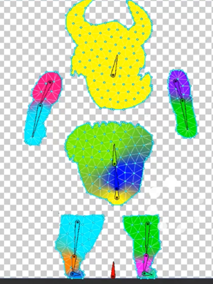
Figure 17.2: Mesh skinning weights visually represented as colors
Finally, the last piece you need is the actual animation, which will simply consist of a blending of different poses of the mesh bones. The artist will create keyframes in an animation, determining which pose the model needs to have at different moments, and then the animation system will simply interpolate between them. Basically, the artist will animate the bones, and the skinning system will apply this animation to the whole mesh.
In order to get the four parts, we need to get the proper assets containing them. The usual format in this scenario is Filmbox (FBX), which we used previously to import 3D models. This format can contain every piece we need—the model, the skeleton with the skinning, and the animations—but usually those pieces will come split into several files to be re-utilized.
Imagine a city simulator game where we have several citizen meshes with different aspects and all of them must be animated. If we have a single FBX per citizen containing the mesh, the skinning, and the animation, it will cause each model to have its own animation, or at least a clone of the same one, repeating them. When we need to change that animation, we will need to update all the mesh citizens, which is a time-consuming process. Instead of this, we can have one FBX per citizen, containing the mesh and the bones with the proper skinning based on that mesh, as well as a separate FBX for each animation, containing the same bones that all the citizens have with the proper animation, but without the mesh. This will allow us to mix and match the citizen FBX with the animation’s FBX files. You may be wondering why both the model FBX and the animation FBX must have the mesh. This is because they need to match in order to make both files compatible. In Figure 17.3, you can see how the files should look:

Figure 17.3: The animation and model FBX files of the package we will use in our project
Also, it is worth mentioning a concept called retargeting. As we said before, in order to mix a model and an animation file, we need them to have the same bone structure, which means the same number of bones, hierarchy, and names.
Sometimes, this is not possible, especially when we mix custom models created by our artist with external animation files that you can record from an actor using motion-capture techniques, or just by buying a mocap (motion-capture) library, a set of animations captured on real humans using specific mocap hardware. In such cases, it is highly likely that you will encounter different bone structures between the one in the mocap library and your character model, so here is where retargeting kicks in. This technique allows Unity to create a generic mapping between two different humanoid-only bone structures to make them compatible. In the next section, Importing skeletal animations, we will see how to enable this feature.
Now that we understand the basics behind skinned meshes, let’s see how we can get the model’s assets with bones and animations.
Importing skeletal animations
We can download a character model by searching for it in the Asset Store, under the 3D | Characters | Humanoids section. You can also use external sites, such as the website called Mixamo, to download them. Note that sometimes you will need to download several packages because sometimes packages come only with the skinned model, and others with animation only. Luckily the one we downloaded already contains the skinned meshes and the animations.
In my package content, I can find the animation’s FBX files in the Animations folder and the FBX file of my model called Polyart_Mesh in the Mesh folder. Remember that sometimes you won’t have them separated like this, and the animations may be located in the same FBX as the model, if any animations are present at all. Now that we have the required files, let’s discuss how to properly configure them.
Let’s start selecting the Model file and checking the Rig tab. Within this tab, you will find a setting called Animation Type, as shown in Figure 17.4:

Figure 17.4: The Rig properties
This property contains the following options:
- None: Mode for non-animated models; every static mesh in your game will use this mode.
- Legacy: The mode to be used in old Unity Projects and models; do not use this in new projects.
- Generic: A new animation system that can be used in all kinds of models but is commonly used in non-humanoid models, such as horses, octopuses, and so on. If you use this mode, both the model and animation FBX files must have the exact same bone names and structure, thereby reducing the possibility of combining animation from external sources.
- Humanoid: New animation systems designed to be used in humanoid models. It enables features such as retargeting and Inverse Kinematics (IK). This allows you to combine models with different bones than the animation because Unity will create a mapping between those structures and a generic one, called the avatar. Take into account that sometimes the automatic mapping can fail, and you will need to correct it manually; so, if your generic model has everything you need, I recommend you stick to Generic if that’s the default configuration of the FBX.
In my case, the FBX files in my package have the modes set to Humanoid, so that’s good, but remember, only switch to other modes if it is absolutely necessary (for example, if you need to combine different models and animations). Now that we have discussed the Rig settings, let’s talk about the Animation settings.
In order to do this, select any animation FBX file and look for the Animation tab in the Inspector window. You will find several settings, such as the Import Animation checkbox, which must be marked if the file has an animation (not the model files), and the Clips list, where you will find all the animations in the file. In the following screenshot, you can see the Clips list for one of our animation files:

Figure 17.5: A Clips list in the Animation settings
An FBX file with animations usually contains a single large animation track, which can contain one or several animations. Either way, by default, Unity will create a single animation based on that track, but if that track contains several animations, you will need to split them manually. In our case, our FBX contains a single animation, but in order to learn how to split it in other cases, do the following:
- From the Clips list, select any animation that you want to recreate; in my case, I will choose
Run_guard_AR. - Take a look at the Start and End values below the animation timeline and remember them; we will use them to recreate this clip:

Figure 17.6: The clip settings
- Use the + button to create a new clip and select it.
- Rename it to something similar to the original using the input field that currently says something like
Take 001. In my case, I will name itRun. - Set the End and Start properties with the values we needed to remember in step 2. In my case, I have
20for End and0for Start. This information usually comes from the artist that made the animation, but you can just try the number that works best or simply drag the blue markers in the timeline on top of these properties. - If an animation needs to loop, check the Loop Time checkbox to guarantee that. This will make the animation repeat constantly, which is required in most animations like Walk or Run. If not, the animation will play once and never repeat:
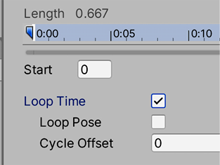
Figure 17.7: Looping the animation
- Preview the clip by clicking on the bar titled for your animation (Run, in my case) at the very bottom of the Inspector window and click on the Play button. You can see the default Unity model in some cases, but you can see your own by dragging the model file to the preview window because it is important to check whether our models are properly configured. If the animation does not play, you will need to check whether the Animation Type setting matches the animation file:
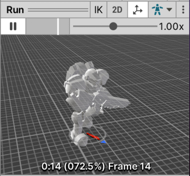
Figure 17.8: Animation preview
- Open the animation asset (the FBX) by clicking the arrow on its left, and check the sub-assets. You will see that there is an asset with the same title as your animation:

Figure 17.9: Generated animation clips
- Remember that there are plenty of other settings aside from the Init frame, End frame, and Loop Time. The character I downloaded required other settings like Root Transform Rotation, Root Transform Position, and Mask to make it work, and the mileage may vary between character packages. If you are recreating an existing animation, consider copying all settings as they were, or just use the default one. These mentioned settings are beyond the scope of the book, but you can always consult them in the Unity documentation at https://docs.unity3d.com/Manual/class-AnimationClip.html.
Now that we have covered the basic configuration, let’s learn how to integrate animations.
Integration using Animation Controllers
When adding animations to our characters, we need to think about the flow of the animations, which means thinking about which animations must be played, when each animation must be active, and how transitions between animations should happen. In previous Unity versions, you needed to code that manually, generating complicated scripts of C# code to handle complex scenarios; but now, we have Animation Controllers.
Animation Controllers are a state machine-based asset where we can diagram the transition logic between animations with a visual editor called Animator. The idea is that each animation is a state and our model will have several of them. Only one state can be active at a time, so we need to create transitions in order to change them, which will have conditions that must be met in order to trigger the transition process. Conditions are comparisons of data about the character to be animated, such as its velocity, whether it’s shooting or crouched, and so on.
So, basically, an Animation Controller or state machine is a set of animations with transition rules that will dictate which animation should be active. Let’s start creating a simple Animation Controller by doing the following:
- Click the + button under the Project view, click on Animator Controller, and call it
Player. Remember to locate your asset within a folder for proper organization; I will call mineAnimations. - Double-click on the asset to open the Animator window. Don’t confuse this window with the Animation window; the Animation window serves to create new Animations, but for now, we will stick with the downloaded ones.
- Search for the Idle animation clip of your character in the Animations folder of your characters package and drag it into the Animator window. In my case it was called Idle_guard_ar. Remember to drag the sub-asset, not the entire file. This will create a box in the Controller representing the animation that will be connected to the entry point of the Controller, indicating that the animation will be the default one because it is the first one that we dragged. If you don’t have an Idle animation, I encourage you to download one from the Asset Store, maybe searching in other characters’ packages. We will need at least one Idle and one walking/running animation clip:

Figure 17.10: Dragging an animation clip from an FBX asset into an Animator Controller
- Drag the running animation in the same way, which is Run_guard_AR in my case.
- Right-click on the Idle animation box in the Animator window, select Make Transition, and left-click on the Run animation. This will create a transition between Idle and Run.
- Create another transition from Run to Idle in the same way:

Figure 17.11: Transitions between two animations
Transitions must have conditions in order to prevent animations from swapping constantly, but in order to create conditions, we need data to make comparisons. We will add properties to our Controller, which will represent data used by the transitions. Later, in the Scripting Animations section of this chapter, we will set that data to match the current state of our object. But for now, let’s create the data and test how the Controller reacts to different values. In order to create conditions based on properties, do the following:
- Click on the Parameters tab in the top-left part of the Animator window. If you don’t see it, click on the button that looks like an eye crossed by a line to display the tabs. The icon will change to an uncrossed eye.
- Click on the + button and select Float to create a number that will represent the velocity of our character, naming it
Velocity. If you missed the renaming part, just left-click on the variable and rename it:

Figure 17.12: The Parameters tab with a float Velocity property
- Click on the Idle to Run transition (the white line with an arrow in the middle) and look at the Conditions property in the Inspector window.
- Click on the + button at the bottom of the list, which will create a condition that will rule the transition. The default setting will take the first parameter of our animator (in this case, it is Velocity) and will set the default comparer, in this case, Greater, to a value of
0. This tells us that the transition will execute from Idle to Run if Idle is the current animation and the velocity of the Player is greater than0. I recommend you set a slightly higher value, such as0.01, to prevent any float rounding errors (a common CPU issue). Also, remember that the actual value of Velocity needs to be set manually via scripting, which we will do in this chapter’s Scripting animations section:

Figure 17.13: Condition to check whether the velocity is greater than 0.01
- Do the same to the Run to Idle transition, but this time, change Greater to Less and again set the value to
0.01:

Figure 17.14: Condition to check whether a value is less than 0.01
Now that we have our first Animator Controller set up, it’s time to apply it to an object. In order to do that, we will need a series of components. First, when we have an animated character, rather than a regular Mesh Renderer, we use the Skinned Mesh Renderer. If you select your player or enemy characters and view their children, GameObjects, you will see the Skinned Mesh Renderer in one or more of them:

Figure 17.15: A Skinned Mesh Renderer component
This component will be in charge of applying the bones’ movements to the mesh. If you search the children of the model, you will find some bones; you can try rotating, moving, and scaling them to see the effect, as shown in the following screenshot. Bear in mind that your bone hierarchy might be different from mine if you downloaded another package from the Asset Store:

Figure 17.16: Rotating the neckbone
The other component that we need is Animator, which is automatically added to the skinned meshes at its root GameObject. This component will be in charge of applying the state machine that we created in the Animator Controller if the animation FBX files are properly configured, as we mentioned earlier. In order to apply the Animator Controller, do the following:
- Select the player in the Hierarchy and locate the Animator component in the root GameObject.
- Click on the circle to the right of the Controller property and select the Player controller we created earlier. You can also just drag it from the Project window.
- Make sure that the Avatar property is set to the avatar inside the FBX model of the character (
Polyart_Meshbeing the FBX model in our example project); this will tell the animator that we will use that skeleton. You can identify the avatar asset by its icon of a person, as shown in the following screenshot. Usually, this property is correctly set automatically when you drag the FBX model to the scene:

Figure 17.17: Animator using the Player controller and the robot avatar
- Without stopping the game, open the Animator Controller asset again by double-clicking it and selecting the character in the Hierarchy pane. By doing this, you should see the current state of the animation being played by that character, using a bar to represent the current part of the animation:

Figure 17.18: The Animator Controller in Play mode while an object is selected, showing the current animation and its progress
- Using the Animator window, change the value of Velocity to
1.0and see how the transition will execute. Feel free to disable the WaveSpawners to test this, given they will probably kill the player before we can safely do so:

Figure 17.19: Setting the velocity of the Controller to trigger a transition
- Depending on how the Run animation was set, your character might start to move instead of executing the animation in place. This is caused by root motion, a feature that will move the character based on the animation movement. Sometimes, this is useful, but due to the fact that we will fully move our character using scripting, we want that feature to be turned off. You can do that by unchecking the Apply Root Motion checkbox in the Animator component of the Character object, as seen in Figure 17.17.
- You will also notice a delay between changing the Velocity value and the start of the animation transition. That’s because, by default, Unity will wait for the original animation to end before executing a transition, but in this scenario, we don’t want that. We need the transition to start immediately. In order to do this, select each transition of the Controller, and in the Inspector window, uncheck the Has Exit Time checkbox. When this property is checked, a hidden condition for the transition to execute is waiting for the animation to end. But with this unchecked, the transition can execute at any moment during the animation, which we want, given that we don’t want any delay between the player being idle and running:

Figure 17.20: Disabling the Has Exit Time checkbox to execute the transition immediately
You can start dragging other animations into the Controller and create complex animation logic, such as adding jump, fall, or crouched animations. I invite you to try other parameter types, such as a Boolean, that use checkboxes instead of numbers. Also, as you develop your game further, your Controller will grow in its number of animations. To manage that, there are other features worth researching, such as Blend Trees and sub-state machines, but that’s beyond the scope of this book.
In this section, we learned how to integrate animation clips into our character through Animator Controllers. We added all needed animations and created the necessary transitions between them to react to the game circumstances, like the character velocity changes.
Now that we have integrated the idle and run animations, let’s integrate the shoot animation, which requires us to use Avatar Masks.
Using Avatar Masks
At first, this case seems as simple as dragging a shoot animation and making transitions that use the Shooting Boolean parameter as a condition. Consider, however, that we can shoot while walking and while running, so that leads to two shooting animations, Walking Shooting and Idle Shooting. If you follow this logic, you can think of shooting while falling, jumping, etc., which leads to a greater number of animation combinations. Imagine having different shooting animations for different weapons! Luckily, we have a better solution: a way to combine several animations, using Avatar Masks.
The animations state machine we created in the Animator Controller is what is called a layer, and an Animator Controller can have several layers. This means that we can have more than one state machine in an Animator Controller. There are several reasons to use this, but the common one is to combine layers with Avatar Masks, an asset that allows us to make a specific Animator Controller layer or state machine to affect certain bones, so we can set different state machines for different parts of the body.
We can use this to solve the shooting scenario we discussed previously, splitting our player animation logic into two parts, the upper part of the body, and the lower part. The idea is that the lower part will switch between idle and running animations, while the upper part can switch between idle, running, and shooting. This allows us to have scenarios where the lower part is running while the upper part is shooting, or the lower part is idle and the upper part also, or any combination we can imagine.
Let’s start by creating the second layer by doing the following:
- Download a shooting animation from the internet or the Asset Store if you don’t have one already. In our case we already have several shooting animations, and we are going to pick the one called
Idle_Shoot_ar. - In the Animator Controller, do a single click in Base Layer and rename it LowerBody. If you don’t see the layers list, click the Layers button at the top-left part of the Animator window:

Figure 17.21: Renaming the base layer
- Add a second layer to the Controller using the + button and rename it
UpperBody. - Select the layer and add the Idle, Runs, and Shoot animations to it, connecting the states with transitions. Remember to uncheck Has Exit Time in each transition:
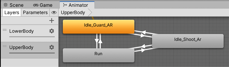
Figure 17.22: UpperBody state machine
- Add the same transition logic between Idle and Run used before, using Velocity as the parameter for the conditions, as before.
- For the shooting transitions, create a Boolean parameter called Shooting:

Figure 17.23: Shooting Boolean
- Make both transitions to shooting (Idle to Shoot and Run to Shoot) execute when the Shooting Boolean is true.
- Make the return transition from Shoot to Idle when the Shooting Boolean is false and Velocity is less than
0.01, and the return from Shoot to Run when Shooting is true and Velocity is greater than0.01:

Figure 17.24: The Shoot to Idle transition at the top, the Shoot to Run transition in the middle, and both the Idle to Shoot and Run to Shoot transitions at the bottom
Now that we have the layers created, let’s apply the Avatar Masks to them:
- Create an Avatar Mask using the + button in the Project View, and name the first one
UpperBodyMask. - Select the
UpperBodyMaskasset in the Inspector and click the arrow on the left where it says Humanoid to expand this section. - Click the lower parts of the body displayed in the Inspector until they become red:

Figure 17.25: UpperBodyMask asset configs
- In the Animator Controller, select the UpperBody layer and click on the wheel to its right to display some options.
- Click at the circle at the right of the Mask property and select the UpperBodyMask asset in the window that appears.
- Click again at the wheel of the UpperBody layer and set its Weight to
1. Since the two layers are affecting different parts of the body, both of them have the same priority. In scenarios where two layers affect the same bones, the weight is used to calculate which one has more influence:

Figure 17.26: Setting the Weight and the Mask of a layer
- Click again on the wheel and observe how the Blending parameter is set to Override, meaning that the bones that this layer affects (driven by the Avatar Mask) will override whatever animation the base layer has—the base layer, in this case, being LowerBody. That’s how this layer takes ownership of the upper part of the body.
- Test this again, changing the values of the parameters while in Play mode. For example, try checking Shooting and then set Velocity to
1, and then to0, to finally uncheck Shooting, and see how the transitions execute. - You might notice that our character might not be pointing in the right direction when shooting. This is because the orientation of the character is modified for this Shoot animation compared to Idle and Run, but the Base Layer still has ownership of that. We can make the UpperBodyMask control the orientation by clicking the circle at the bottom of the human figure in the Humanoid section of the Avatar Mask until it becomes green:

Figure 17.27: Giving the mask authority over the player orientation
The issue here is that you will now see the character moving the feet sideways when running and shooting. There’s no easy solution here other than to modify the original animations. In this case, this character has Idle, Idle Shooting, Run and Run Shooting animations, so it clearly has been created without having Avatar Masks in mind, instead just having all possible animation combinations. An alternative is to find another package that works better with Avatar Masks. For learning purposes, we will stick with this, but note that Avatar Masks are not a must; you might be good to go just using all possible animation permutations in a single Animator Controller state machine with all the needed transitions.
Another issue you might notice when firing when the Shoot animation is playing is that the muzzle effect will stay in the original position of the weapon. Since the weapon mesh is affected by the skinning animation but not its Transform position, the muzzle cannot follow it. In order to solve this, you can reparent the Muzzle Effect to one of the bones of the weapons—in this case, the GameObject called Trigger_Right, one of the children of the Hips GameObject. Not all animations will have bones for the weapons, so this is one of the possible scenarios you could face:

Figure 17.28: Reparenting the Muzzle Effect to one of the weapon’s bones
- Remember to apply the same changes we made to our player to the enemy, which means adding and setting the Player Animator Controller to its Animator component and changing the
Muzzle effectparent.
Now that we have a fully functional Animator Controller, let’s make it reflect the player movement through scripting.
Scripting animations
With our player’s Animator ready, it is time to do some scripting to make these parameters be affected by the actual behavior of the player and match the player’s. In this section we will do the following to achieve this:
- Script shooting animations
- Script movement animations
Let’s start making our characters execute the Shoot animation when necessary.
Scripting player shooting animations
So far, we have created a behavior to shoot each time we press a key, but the animation is prepared for sustained fire. We can make our PlayerShooting script shoot a bullet every X number of seconds while we keep the Fire key pressed to match the animation, instead of having to press the key repeatedly.
Let’s see how to do this:
- In the PlayerShooting script, add a public float field called fireRate, which will measure the seconds between bullet spawns. Remember to set this value in the Inspector of the player.
- Change the OnFire method to the code seen in Figure 17.29. The idea is to start a repeating action when we press the key and stop it when we release the key. We are using InvokeRepeating to repeatedly execute a function called Shoot, which we will be creating in the next step. The rate of execution will be controlled by the fireRate field we created in step 1:

Figure 17.29: OnFire changes needed for sustained fire
- Add the Shoot method as seen in Figure 17.30 to our PlayerShooting script. This is essentially the same code we had before in the OnFire method but separated in a function, so we can execute it several times with the InvokeRepeating function:

Figure 17.30: OnFire changes needed for sustained fire
If you try these changes now, you will notice the bullets will never stop shooting once we click the Fire button. Even worse, as we press repeatedly, more and more bullets will be shot. With some debugging or educated guessing, you might figure out that the CancelInvoke method is not being executed. The reason behind this is that the Fire input mapping is not configured by default to inform us about the release of keys, just when they were pressed. Luckily the solution is pretty simple:
- Double-click the SuperShooter inputs asset, the one we created in Chapter 6, Implementing Movement and Spawning, that contains all the inputs our game supports.
- Select the Fire action in the Actions list (the middle column).
- Click the + button at the right of the Interactions section and click Press.
- Set the Trigger Behavior of the Press section to Press And Release:
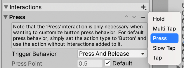
Figure 17.31: OnFire changes needed for sustained fire
- With this we have configured the Input to not only tell us when the key was pressed but also when it was released, making our CancelInvoke method execute now.
Now that we have our constant fire behavior, we can do the following to make the animation reflect this:
- Add a reference to Animator using GetComponent in Awake and cache it in a field, as seen in Figure 17.32:

Figure 17.32: Caching the Animator reference
- Add the line
animator.SetBool("Shooting", value.isPressed);at the beginning of the OnFire method:

Figure 17.33: Setting the Shooting animation parameter to reflect input
- The idea behind this change is to make sure the Shooting animation parameter reflects the state of the fire key, meaning that the
Shootanimation will play as long as the Fire button is pressed, and will stop when we release it.
One thing you will notice is that the bullets are still being shot from the player’s chest because our ShootPoint GameObject, the one that defines the shooting position, is not positioned in front of the weapon. Just re-parent the ShootPoint to the weapon bone (Trigger_Right in our case) and position it to be in front of the weapon. Remember to make the forward vector (the blue arrow in the Scene view) point along the weapon:

Figure 17.34: Adapting the ShootPoint to follow the animation
For the Visual Scripting version, in order to make the bullet get shot constantly, you should change the Input nodes of PlayerShooting like in Figure 17.35:

Figure 17.35: Creating a shoot loop
As you can see, we used a new node called Timer. The idea of Timer is similar to the Wait For Seconds node we used before, because it allows us to delay the execution of one action. One of the main differences is that it allows us to cancel the timer before it executes again, meaning we can start the timer when we press the Fire key, and stop it when we release it. We did that by connecting the InputSystemEventButton node that has the OnPressed mode to the Start pin of the Timer, and the one with the OnReleased mode to the Pause pin. Also, we created a new variable called fireRate and connected it to the Duration pin of the Timer, so we need to specify how much time the Timer will wait before instantiating our bullets. See how we connected the Completed pin of the Timer to the If node that checks if we have enough bullets to instantiate; we used to connect to the input node here before.
One little missing detail here is that when we press a key, time will pass (fireRate) and then a bullet will be instantiated, but then nothing else. We need to connect the end of the Bullet shoot sequence (the AudioSource: Play node in this case) of nodes again to the Start pin of the Timer to create a spawn loop. That loop will be interrupted when we release the key, to prevent it from being executed forever:

Figure 17.36: Completing the shoot loop
Finally, we need to add the proper Animator: SetBool(Name, Value) node to the Input nodes to turn on and off the Boolean and trigger the animation:

Figure 17.37: Executing the Shoot animation
Now that we have handled the Shoot animations of the player, let’s handle the one of the enemy by doing the following:
- Cache a reference to the parent animator in the EnemyFSM script using GetComponentInParent as we did with the NavMeshAgent:

Figure 17.38: Accessing the parent’s Animator reference
- Turn on the Shooting animator parameter inside the Shoot function to make sure that every time we shoot, that parameter is set to true (checked):

Figure 17.39: Turning on the shooting animation
- Turn off the
Shootingparameter in all non-shooting states, such as GoToBase and ChasePlayer:

Figure 17.40: Turning off the shooting animation

Figure 17.41: GoToBase state
- Note that we needed again the GetParent node to access the enemy’s parent Transform (the root), which we connected to the Animator: SetBool node in order to access the Animator in the enemy’s root. Then the ChasePlayer state actions will look like this:

Figure 17.42: ChasePlayer state

Figure 17.43: Attack Base state
With this, both our player and enemies have a constant shooting behavior and a Shoot animation to reflect this. Now let’s handle the movement animations for both.
Scripting movement animations
For the animator controller’s Velocity parameter, we can detect the magnitude of the velocity vector of Rigidbody, the velocity in meters per second, and set that as the current value. This can be perfectly separated from the PlayerMovement script, so we can reuse this if necessary, in other scenarios. So, we need to create a script such as the one in the following image, which just connects the Rigidbody component’s velocity with the animator Velocity parameter, and adds it to the Player GameObject:

Figure 17.44: Setting VelocityAnimator variables
And regarding the Visual Scripting version, this is what it would look like:

Figure 17.45: Setting Velocity Animator variables in Visual Scripting
You may need to increase the 0.01 transitions threshold used so far in the conditions of the transitions of the animator controller because Rigidbody keeps moving after releasing the keys. Using 1 worked perfectly for me. Another option would be to increase the drag and the velocity of the player to make the character stop faster. Pick whatever method works best for you. Remember the transitions of both layers (UpperBody and LowerBody).
Now we can add the movement animations to the enemy. Create and add a script to the Enemy prefab called NavMeshAnimator, which will take the current velocity of its NavMeshAgent and will set it to the Animator Controller. This will work similarly to the VelocityAnimator script but this time checking the velocity of the NavMeshAgent. We didn’t use VelocityAnimator here because our AI doesn’t use Rigidbody to move, so it won’t work:

Figure 17.46: Connecting the NavMeshAgent to our Animator Controller
The Visual Scripting version will look like this:

Figure 17.47: Setting the animator velocity parameter the same as our NavMeshAgent
Notice here we don’t need the GetParent node, given that this graph is located at the Enemy’s root object alongside the Animator and the NavMeshAgent. With that, we have scripted our Player and Enemies animations. We are ready to keep learning about animations using Cinemachine to create cutscene cameras and much more.
Creating dynamic cameras with Cinemachine
Cameras are a very important subject in video games. They allow the player to see their surroundings to make decisions based on what they see. The game designer usually defines how it behaves to get the exact gameplay experience they want, and that’s no easy task. A lot of behaviors must be layered to get the exact feeling. Also, for cutscenes, it is important to control the path that the camera will be traversing during it and where the camera is looking to focus the action during those constantly moving scenes.
In this chapter, we will use the Cinemachine package to create both the dynamic cameras that will follow the player’s movements, which we will code in Part 3, and also, the cameras to be used during cutscenes.
In this section, we will examine the following Cinemachine concepts:
- Creating camera behaviors
- Creating dolly tracks
Let’s start by discussing how to create a Cinemachine-controlled camera and configure behaviors in it.
Creating camera behaviors
Cinemachine is a tech library containing a collection of different behaviors that can be used in a camera, which when properly combined can generate all kinds of common camera types in video games, including following the player from behind, first-person cameras, top-down cameras, and so on. In order to use these behaviors, we need to understand the concept of brains and virtual cameras.
In Cinemachine, we will only keep one main camera, as we have done so far, and that camera will be controlled by virtual cameras, separated GameObjects that have the aforementioned behaviors. We can have several virtual cameras and swap between them at will, but the active virtual camera will be the only one that will control our main camera. This is useful for switching cameras at different points of the game, such as switching between our player’s third-person camera and a cutscene camera. In order to control the main camera with the virtual cameras, it must have a Brain component, which will monitor all active virtual cameras and pick the proper position to use them.
To start using Cinemachine, first, we need to check if it is installed in the Package Manager, as we did previously with other packages. If you don’t remember how to do this, just do the following:
- Go to Window | Package Manager.
- Ensure that the Packages option in the top-left part of the window is set to Unity Registry:

Figure 17.48: The Packages filter mode
- Wait a moment for the left panel to populate all packages from the servers (the internet is required).
- Look for the Cinemachine package from the list and select it. At the moment of writing this book the latest available version is 2.8.6, but you can use newer versions if you prefer, always ensuring that the following steps work as expected; if not, you can always install the closest version to ours.
- If you see the Install button in the bottom-right corner of the screen it means it is not installed. Just click that button.
Now that we have it installed, we can start creating a virtual camera to follow the player. So far, we just simply parented the camera to the player for it to follow them, but now we will unparent the camera and let Cinemachine handle it to learn how to use this tool:
- Select the MainCamera inside the player and unparent it (drag it outside the player) in such a way that it becomes a root object of our scene, having no parent at all.
- Click GameObject | Cinemachine | Virtual Camera. This will create a new object called
CM vcam1:
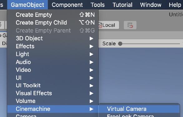
Figure 17.49: Virtual camera creation
- If you select the main camera from the Hierarchy pane, you will also notice that a
CinemachineBraincomponent has been automatically added to it, making our main camera follow the virtual camera. Try to move the created virtual camera, and you will see how the main camera follows it:

Figure 17.50: The CinemachineBrain component
- Select the virtual camera (
CM vcam1) and drag the character to the Follow and Look At properties of the CinemachineVirtualCamera component. This will make the movement and looking behaviors use that object to do their jobs:

Figure 17.51: Setting the target of our camera
- You can see how the Body property of the virtual camera is set to Transposer, which will move the camera relative to the target set at the Follow property—in our case, the character. You can open the Body options (the arrow to its left), change the Follow Offset property, and set it to the desired distance you want the camera to have from the target. In my case, I used the
0,3, and-3values:

Figure 17.52: The camera following the character from behind
- Figure 17.50 shows the Game view; you can see a small, yellow rectangle indicating the target position to look at the character, and it’s currently pointing at the pivot of the character—its feet. If you don’t see it open the Aim section of the virtual camera in the Inspector by clicking the arrow to its left.
- We can apply an offset in the Tracked Object Offset property of the Aim section of the virtual camera. In my case, a value of
0,1.8, and0worked well to make the camera look at the head instead:

Figure 17.53: Changing the Aim offset
As you can see, using Cinemachine is pretty simple, and in our case, the default settings were mostly enough for the kind of behavior we needed. However, if you explore the other Body and Aim modes, you will find that you can create any type of camera for any type of game. We won’t cover the other modes in this book, but I strongly recommend you look at the documentation for Cinemachine to check what the other modes do. To open the documentation, follow these steps:
- Open the Package Manager by going to Window | Package Manager.
- Find Cinemachine in the left-hand side list. Wait a moment if it doesn’t show up. Remember that you need an internet connection for it to work.
- Once Cinemachine is selected, scroll down in the right panel until you see the View documentation link in blue. Click on it:

Figure 17.54: The Cinemachine documentation link
- You can explore the documentation using the navigation menu on the left:

Figure 17.55: The Cinemachine documentation
As you did with Cinemachine, you can find other packages’ documentation in the same way. Now that we have achieved the basic camera behavior that we need, let’s explore how we can use Cinemachine to create a camera for our intro cutscene.
Creating dolly tracks
When the player starts the level, we want a little cutscene with a pan over our scene and the base before entering the battle. This will require the camera to follow a fixed path, and that’s exactly what Cinemachine’s dolly camera does. It creates a path where we can attach a virtual camera so that it will follow it. We can set Cinemachine to move automatically through the track or follow a target to the closest point to the track; in our case, we will use the first option.
In order to create a dolly camera, follow these steps:
- Let’s start creating the track with a cart, which is a little object that will move along the track, which will be the target to follow the camera. To do this, click on GameObject | Cinemachine | Dolly Track with Cart:

Figure 17.56: A dolly camera with a default straight path
- If you select the
DollyTrack1object, you can see two circles with the numbers0and1in the Scene view. These are the control points of the track. Select one of them and move it as you move other objects, using the arrows of the translation gizmo. If you don’t see them press the W key to enable the Translation gizmo. - You can create more control points by clicking the + button at the bottom of the Waypoints list of the
CinemachineSmoothPathcomponent of theDollyTrack1object:

Figure 17.57: Adding a path control point
- Create as many waypoints as you need to create a path that will traverse the areas you want the camera to oversee in the intro cutscene. Remember, you can move the waypoints by clicking on them and using the translation gizmo:

Figure 17.58: A dolly track for our scene. It ends right behind the character
- Create a new virtual camera. If you go to the Game view after creating it, you will notice that the character camera will be active. In order to test how the new camera looks, select the previous one (CM vcam1) and temporarily disable it by clicking the checkbox to the left of the GameObject’s name in the Inspector.
- Set the Follow target this time to the
DollyCart1object that we previously created with the track. - Set Follow Offset of the Body section to
0,0, and0to keep the camera in the same position as the cart. - Set Aim to Same As Follow Target to make the camera look in the same direction as the cart, which will follow the track curves:
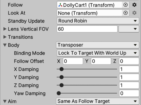
Figure 17.59: Configuration to make the virtual camera follow the dolly track
- Select the DollyCart1 object and change the Position value to see how the cart moves along the track. Do this while the game window is focused and CM vcam2 is in solo mode to see how the camera will look:

Figure 17.60: The dolly cart component
- Re-enable
CM vcam1.
With the dolly track properly set, we can create our cutscene using Timeline to sequence it.
Creating cutscenes with Timeline
We have our intro camera, but that’s not enough to create a cutscene. A proper cutscene is a sequence of actions happening at the exact moment that they should happen, coordinating several objects to act as intended. We can have actions such as enabling and disabling objects, switching cameras, playing sounds, moving objects, and so on. To do this, Unity offers Timeline, which is a sequencer of actions to coordinate those kinds of cutscenes. We will use Timeline to create an intro cutscene for our scene, showing the level before starting the game.
In this section, we will examine the following Timeline concepts:
- Creating animation clips
- Sequencing our intro cutscene
We are going to see how to create our own animation clips in Unity to animate our GameObjects and then place them inside a cutscene to coordinate their activation, using the Timeline sequencer tool. Let’s start by creating a camera animation to use later in Timeline.
Creating animation clips
This is actually not a Timeline-specific feature but rather a Unity feature that works great with Timeline. When we downloaded the character, it came with animation clips that were created using external software, but you can create custom animation clips using Unity’s Animation window. Don’t confuse it with the Animator window, which allows us to create animation transitions that react to the game situation. This is useful to create small object-specific animations that you will coordinate later in Timeline with other objects’ animations.
These animations can control any value of an object’s component properties, such as the positions, colors, and so on. In our case, we want to animate the dolly track’s Position property to make it go from start to finish in a given time. In order to do this, do the following:
- Select the
DollyCart1object. - Open the Animation (not Animator) window by going to Window | Animation | Animation.
- Click on the Create button at the center of the Animation window. Remember to do this while the dolly cart (not track) is selected:

Figure 17.61: Creating a custom animation clip
- After doing this, you will be prompted to save the animation clip somewhere. I recommend you create an
Animationsfolder in the project (inside theAssetsfolder) and call itIntroDollyTrack.
If you pay attention, the dolly cart now has an Animator component with an Animator Controller created, which contains the animation we just created. As with any animation clip, you need to apply it to your object with an Animator Controller; custom animations are no exception. So, the Animation window created them for you.
Animating in this window consists of specifying the value of its properties at given moments. In our case, we want Position to have a value of 0 at the beginning of the animation, at 0 seconds on the timeline, and have a value of 254 at the end of the animation, at 5 seconds. I chose 254 because that’s the last possible position in my cart, but that depends on the length of your dolly track. Just test which is the last possible position in yours. Also, I chose 5 seconds because that’s what I feel is the correct length for the animation, but feel free to change it as you wish. Now, whatever happens between the animation’s 0 and 5 seconds is an interpolation of the 0 and 254 values, meaning that in 2.5 seconds, the value of Position will be 127. Animating always consists of interpolating different states of our object at different moments.
In order to do this, follow these steps:
- In the Animation window, click on the record button (the red circle in the top-left section). This will make Unity detect any changes in our object and save them to the animation. Remember to do this while you have selected the dolly cart.
- Set the Position setting of the dolly cart to
1and then0. Changing this to any value and then to0again will create a keyframe, which is a point in the animation that says that at0seconds, we want the Position value to be0. We need to set it first to any other value if the value is already at0.
You will notice that the Position property has been added to the animation:

Figure 17.62: The animation in Record mode after changing the Position value to 0
- Using the mouse scroll wheel, zoom out the timeline to the right of the Animation window until you see 5:00 seconds in the top bar:

Figure 17.63: The timeline of the Animation window seeing 5 seconds
- Click on the 5:00-second label in the top bar of the timeline to position the playback header at that moment. This will locate the next change we do at that moment.
- Set the Position value of the dolly track to the highest value you can get; in my case, this is
240. Remember to have the Animation window in Record mode:

Figure 17.64: Creating a keyframe with the 240 value 5 seconds into the animation
- Hit the play button in the top-left section of the Animation window to see the animation playing. Remember to view it in the Game view while
CM vcam1is disabled.
Now, if we hit Play, the animation will start playing, but that’s something we don’t want. In this scenario, the idea is to give control of the cutscene to the cutscene system, Timeline, because this animation won’t be the only thing that needs to be sequenced in our cutscene. One way to prevent the Animator component from automatically playing the animation we created is to create an empty animation state in the Controller and set it as the default state by following these steps:
- Search the Animator Controller that we created at the same time as the animation and open it. If you can’t find it, just select the dolly cart and double-click on the Controller property of the Animator component on our GameObject to open the asset.
- Right-click on an empty state in the Controller and select Create State | Empty. This will create a new state in the state machine as if we created a new animation, but it is empty this time:

Figure 17.65: Creating an empty state in the Animator Controller
- Right-click on New State and click on Set as Layer Default State. The state should become orange:

Figure 17.66: Changing the default animation of the Controller to an empty state
- Now, if you hit Play, no animation will play as the default state of our dolly cart is empty. No transition will be required in this case.
Now that we have created our camera animation, let’s start creating a cutscene that switches from the intro cutscene camera to the player camera by using Timeline.
Sequencing our intro cutscene
Timeline is already installed in your project, but if you go to the Package Manager of Timeline, you may see an Update button to get the latest version if you need some of the new features. In our case, we will keep the default version included in our project (1.5.2, at the time of writing this book).
The first thing we will do is create a cutscene asset and an object in the scene responsible for playing it. To do this, follow these steps:
- Create an empty GameObject using the GameObject | Create Empty option.
- Select the empty object and call it
Director. - Go to Window | Sequencing | Timeline to open the Timeline editor.
- Click the Create button in the middle of the Timeline window while the Director object is selected to convert that object into the cutscene player (or director).
- After doing this, a window will pop up asking you to save a file. This file will be the cutscene or timeline; each cutscene will be saved in its own file. Save it in a
Cutscenesfolder in your project (theAssetsfolder). - Now, you can see that the Director object has a Playable Director component with the Intro cutscene asset saved in the previous step set for the Playable property, meaning this cutscene will be played by the Director:

Figure 17.67: Playable Director prepared to play the Intro Timeline asset
Now that we have the Timeline asset ready to work with, let’s make it sequence actions. To start, we need to sequence two things—first, the cart position animation we did in the last step and then the camera swap between the dolly track camera (CM vcam2) and the player cameras (CM vcam1). As we said before, a cutscene is a sequence of actions executing at given moments, and in order to schedule actions, you will need tracks. In Timeline, we have different kinds of tracks, each one allowing you to execute certain actions on certain objects. We will start with the animation track.
The animation track will control which animation a specific object will play; we need one track per object to animate. In our case, we want the dolly track to play the Intro animation that we created, so let’s do that by following these steps:
- Add an Animation track by clicking the plus button (+) and then Animation Track:

Figure 17.68: Creating an animation track
- Select the Director object and check the Bindings list of the Playable Director component in the Inspector window.
- Drag the Cart object to specify that we want the animation track to control its animation:

Figure 17.69: Making the animation track control the dolly cart animation in this Director
Timeline is a generic asset that can be applied to any scene, but as the tracks control specific objects, you need to manually bind them in every scene. In our case, we have an animation track that expects to control a single animator, so in every scene, if we want to apply this cutscene, we need to drag the specific animator to control it in the Bindings list.
- Drag the Intro animation asset that we created to the animation track in the Timeline window. This will create a clip in the track showing when and for how long the animation will play. You can drag as many animations as possible that the cart can play into the track to sequence different animations at different moments, but right now, we want just that one:
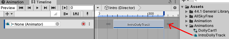
Figure 17.70: Making the animator track play the intro clip
- You can drag the animation to change the exact moment you want it to play. Drag it to the beginning of the track.
- Hit the Play button in the top-left part of the Timeline window to see it in action. You can also manually drag the white arrow in the Timeline window to view the cutscene at different moments. If that doesn’t work try playing the game and then stopping:

Figure 17.71: Playing a timeline and dragging the playback header
- Now, we will make our Intro timeline asset tell the
CinemachineBraincomponent (the main camera) which camera will be active during each part of the cutscene, switching to the player camera once the camera animation is over. We will create a second track—a Cinemachine track—which is specialized in making a specificCinemachineBraincomponent to switch between different virtual cameras. To do this, follow these steps: - Click the + button again and click on Cinemachine Track. Note that you can install Timeline without Cinemachine, but this kind of track won’t show up in that case:

Figure 17.72: Creating a new Cinemachine track
- In the Playable Director component’s Bindings list, drag the main camera to Cinemachine Track to make that track control which virtual camera will control the main camera at different moments of the cutscene:

Figure 17.73: Binding the main camera to the Cinemachine track
- The next step indicates which virtual camera will be active during specific moments of the timeline. To do so, our Cinemachine track allows us to drag virtual cameras to it, which will create virtual camera clips. Drag both CM vcam2 and CM vcam1, in that order, to the Cinemachine track:

Figure 17.74: Dragging virtual cameras to the Cinemachine track
- If you hit the Play button or just drag the Timeline Playback header, you can see how the active virtual camera changes when the playback header reaches the second virtual camera clip. Remember to view this in the Game view.
- If you place the mouse near the ends of the clips, a resize cursor will show up. If you drag them, you can resize the clips to specify their duration. In our case, we will need to match the length of the
CM vcam2clip to the Cart animation clip and then putCM vcam1at the end of it by dragging it so that the camera will be active when the dolly cart animation ends. In my case, they were already the same length, but just try to change it anyway to practice. Also, you can make theCM vcam1clip shorter; we just need to play it for a few moments to execute the camera swap. - You can also overlap the clips a little bit to make a smooth transition between the two cameras, instead of a hard switch, which will look odd:

Figure 17.75: Resizing and overlapping clips to interpolate them
- Increase the Start Time property of the WaveSpawners to prevent the enemies from being spawned before the cutscene begins.
If you wait for the full cutscene to end, you will notice how at the very end, CM vcam2 becomes active again. You can configure how Timeline will deal with the end of the cutscene, as by default, it does nothing. This can cause different behavior according to the type of track–in our case, again giving control to pick the virtual camera to the CinemachineBrain component, which will pick the virtual camera with the highest Priority value. We can change the Priority property of the virtual cameras to be sure that CM vcam1 (the player camera) is always the more important one, or set Wrap Mode of the Playable Director component to Hold, which will keep everything as the last frame of the timeline specifies. In our case, we will use the latter option to test the Timeline-specific features:
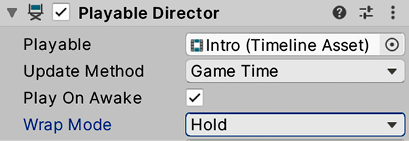
Figure 17.76: Wrap Mode set to Hold mode
Most of the different kinds of tracks work under the same logic; each one will control a specific aspect of a specific object using clips that will execute during a set time. I encourage you to test different tracks to see what they do, such as Activation, which enables and disables objects during the cutscene. Remember, you can check out the documentation of the Timeline package in the Package Manager.
Summary
In this chapter, we introduced the different animation systems that Unity provides for different requirements. We discussed importing character animations and controlling them with Animation Controllers. We also saw how to make cameras that can react to the game’s current situation, such as the player’s position, or that can be used during cutscenes. Finally, we looked at Timeline and the animation system to create an intro cutscene for our game. These tools are useful for making the animators in our team work directly in Unity without the hassle of integrating external assets (except for character animations) and also preventing the programmer from creating repetitive scripts to create animations, wasting time in the process.
Now, you are able to import and create animation clips in Unity, as well as apply them to GameObjects to make them move according to the clips. Also, you can place them in the Timeline sequencer to coordinate them and create cutscenes for your game. Finally, you can create dynamic cameras to use in-game or in cutscenes.
With this, we end Part 2, where we learned about different Unity Systems to improve several artistic aspects of our game. In the next chapter, the first chapter of Part 3, we will wrap up the development of our game, seeing how to build and optimize our game, and also provide a quick intro to augmented reality applications.