
9
Implementing Game AI for Building Enemies
What is a game if not a great challenge to the player, who needs to use their character’s abilities to tackle different scenarios? Each game imposes different kinds of obstacles on the player, and the main one in our game is the enemies. Creating challenging and believable enemies can be complex; they need to behave like real characters and be smart enough so as not to be easy to kill, but also easy enough that they are not impossible to kill. We are going to use basic but sufficient AI techniques to make an AI capable of sensing its surroundings and, based on that information, make decisions on what to do, using FSMs or Finite State Machines, along with other techniques. Those decisions will be executed using intelligent pathfinding.
In this chapter, we will examine the following AI concepts:
- Gathering information with sensors
- Making decisions with FSMs
- Executing FSM actions
By the end of the chapter, you will have a fully functional enemy capable of detecting the player and attacking them, so let’s start by seeing first how to make the sensor systems.
Gathering information with sensors
An AI works by first taking in information about its surroundings. Then, that data is analyzed in order to choose an action, and finally, the chosen action is executed. As you can see, we cannot do anything without information, so let’s start with that part.
There are several sources of information our AI can use, such as data about itself (life and bullets) or maybe some game state (winning condition or remaining enemies), which can easily be found with the code we’ve seen so far. One important source of information, however, is also the AI senses. According to the needs of our game, we might need different senses such as sight and hearing, but in our case, sight will be enough, so let’s learn how to code that.
In this section, we will examine the following sensor concepts:
- Creating three-filter sensors with C#
- Creating three-filter sensors with Visual Scripting
- Debugging with gizmos
Let’s start by seeing how to create a sensor with the three-filters approach.
Creating three-filter sensors with C#
The common way to code senses is through a three-filters approach to discard enemies out of sight. The first filter is a distance filter, which will discard enemies too far away to be seen, then the second filter would be the angle check, which will check enemies inside our viewing cone, and finally, the third filter is a raycast check, which will discard enemies that are being occluded by obstacles such as walls.
Before starting, a word of advice: we will be using vector mathematics here, and covering those topics in-depth is outside the scope of this book. If you don’t understand something, feel free to just search online for the code in the screenshots.
Let’s code sensors in the following way:
- Create an empty
GameObjectcalledAIas a child of the Enemy Prefab. You need to first open the Prefab to modify its children (double-click the Prefab). Remember to set the transform of thisGameObjectto Position 0,1.75,0, Rotation 0,0,0, and Scale 1,1,1 so it will be aligned to the enemy’s eyes. This is done this way for the future sight sensors we will do. Consider your enemy prefab might have a different height for the eyes. While we can certainly just put all AI scripts directly in the Enemy Prefab rootGameObject, we did this just for separation and organization:

Figure 9.1: AI scripts container
- Create a script called
Sightand add it to theAIchild object. - Create two fields of the
floattype calleddistanceandangle, and another two of theLayerMasktype calledobstaclesLayersandobjectsLayers.distancewill be used as the vision distance,anglewill determine the amplitude of the view cone,obstacleLayerswill be used by our obstacle check to determine which objects are considered obstacles, andobjectsLayerswill be used to determine what types of objects we want theSightcomponent to detect.We just want the sight to see enemies; we are not interested in objects such as walls or power-ups.
LayerMaskis a property type that allows us to select one or more layers to use inside code, so we will be filtering objects by layer. In a moment, you will see how we use it:
Figure 9.2: Fields to parametrize our sight check
- In
Update, callPhysics.OverlapSphereas in the Figure 9.3.
This function creates an imaginary sphere in the place specified by the first parameter (in our case, our position) and with a radius specified in the second parameter (the distance property) to detect objects with the layers specified in the third parameter (ObjectsLayers). It will return an array with all the colliders found inside the sphere; these functions use physics to carry out the check, so the objects must have at least one collider.
This is the method we will be using to find all enemies inside our view distance, and we will be further filtering them in the next steps. Note that we are passing our position to the first parameter, which is not actually the position of the enemy but the position of the AI child object, given our script is located there. This highlights the importance of the position of the AI object.
Another way of accomplishing the first check is to just check the distance from the objects we want to see to the player, or if looking for other kinds of objects, to a Manager component containing a list of them. However, the method we chose is more versatile and can be used for any kind of object.
Also, you might want to check the Physics.OverlapSphereNonAlloc version of this function, which does the same but is more performant by not allocating an array to return the results.
- Iterate over the array of objects returned by the function using a
forloop:

Figure 9.3: Getting all GameObjects at a certain distance
- To detect whether the object falls inside the vision cone, we need to calculate the angle between our viewing direction and the direction from ourselves towards the object itself. If the angle between those two directions is less than our cone angle, we consider that the object falls inside our vision. We will do that in the following steps:
Start calculating the direction toward the object, which can be done by normalizing the difference between the object’s position and ours, like in Figure 9.4. You might notice we used
bounds.centerinstead oftransform.position; this way, we check the direction to the center of the object instead of its pivot. Remember that the player’s pivot is in the ground and the ray check might collide against it before the player:
Figure 9.4: Calculating direction from our position toward the collider
- We can use the
Vector3.Anglefunction to calculate the angle between two directions. In our case, we can calculate the angle between the direction toward the enemy and our forward vector to see the angle:

Figure 9.5: Calculating the angle between two directions
If you want, you can instead use Vector3.Dot, which will execute a dot product, a mathematics function to calculate the length of a vector projected to another (search online for more info). Vector3.Angle actually uses that one, but converts the result of the dot product into an angle, which needs to use trigonometry, and that can be time expensive to calculate. But our Vector3.Angle approach is simpler and faster to code, and given that we don’t require many sensors because we won’t have many enemies, optimizing the sensor using dot products is not necessary now, but consider that for games with larger scale.
- Now check whether the calculated angle is less than the one specified in the
anglefield. Note that if we set an angle of90, it will actually be180, because if theVector3.Anglefunction returns, as an example,30, it could be30to the left or to the right. If our angle says90, it could be both90to the left and to the right, so it will detect objects in a 180-degree arc. - Use the
Physics.Linecastfunction to create an imaginary line between the first and the second parameter (our position and the collider position) to detect objects with the layers specified in the third parameter (the obstacle layers) and returnbooleanindicating whether that ray hit something or not.The idea is to use the line to detect whether there are any obstacles between ourselves and the detected collider, and if there is no obstacle, this means that we have a direct line of sight toward the object. Observe how we use the
!ornotoperator in Figure 9.6 to check ifPhysics.Linecastdidn’t detect any objects. Again, note that this function depends on the obstacle objects having colliders, which in our case, we have (walls, floor, and so on):
Figure 9.6: Using a Linecast to check obstacles between the sensor and the target object
- If the object passes the three checks, that means that this is the object we are currently seeing, so we can save it inside a field of the
Collidertype calleddetectedObject, to save that information for later usage by the rest of theAIscripts.Consider using
breakto stop theforloop that is iterating the colliders to prevent wasting resources by checking the other objects, and to setdetectedObjecttonullbeforeforto clear the result from the previous frame. So if in this frame, we don’t detect anything, it will keep thenullvalue so we notice that there is nothing in the sensor:

Figure 9.7: Full sensor script
In our case, we are using the sensor just to look for the player, the only object the sensor is in charge of looking for, but if you want to make the sensor more advanced, you can just keep a list of detected objects, placing inside it every object that passes the three tests instead of just the first one. In our case, it’s not necessary given we have only one player in the game.
- In the editor, configure the sensor at your will. In this case, we will set
ObjectsLayertoPlayerso our sensor will focus its search on objects with that layer, andobstaclesLayertoDefault, the layer we used for walls and floors. Remember theSightscript is in theAIGameObject, which is a child of theEnemyprefab:

Figure 9.8: Sensor settings
- To test this, just place an enemy with a movement speed of 0 in front of the player, select its
AIchild object and then play the game to see how the property is set in the Inspector. Also, try putting an obstacle between the two and check that the property says None (null). If you don’t get the expected result, double-check your script, its configuration, and whether the player has thePlayerlayer, and the obstacles have theDefaultlayer. Also, you might need to raise theAIobject a little bit to prevent the ray from starting below the ground and hitting it.
Given the size of the script, let’s dedicate an entire section to the Visual Scripting version, given it also introduces some new Visual Scripting concepts needed here.
Creating Three-Filters sensors with Visual Scripting
Regarding the Visual Scripting version, let’s check it part by part, starting with the Overlap Sphere:

Figure 9.9: Overlap Sphere in Visual Scripting
So far, we just called Overlap Sphere after setting the sensedObject variable to null. Something to consider is how the sensedObject variable in the Variables component in the Inspector doesn’t have a type (a Null type is no type in Visual Scripting). This can’t be possible in C#—all variables must have a type—and while we could set the sensedObject variable to the proper type (Collider), we will keep the variable type to be set later via a script. Even if we set the type now, Visual Scripting tends to forget the type if no value is set, and we cannot set it until we detect something.
Don’t worry about that for the moment; when we set the variable through our script it will acquire the proper type. Actually, all variables in Visual Scripting can switch types at runtime according to what we set them to, given how the Variables component works. I don’t recommend doing that, though: try to stick with the intended variable type.
We just said that all variables in C# must have a type, but that’s not entirely true. There are ways to create dynamically-typed variables, but it’s not a good practice that I’d recommend using unless no other option is present.
Another thing to observe is how we set the sensedObject variable to null at the beginning using the Null node, which effectively represents the null value.
Now, let’s explore the Foreach part:
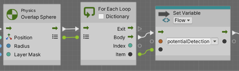
Figure 9.10: Iterating collections in Visual Scripting
We can see that one of the output pins of Overlap Sphere is a little list, which essentially represents the collider array returned by Overlap Sphere. We connect that pin to the For Each Loop node, which as you might imagine iterates over the elements of the provided collection (array, list, dictionary, etc.). The Body pin represents the nodes to execute in each iteration of the loop, and the Item output pin represents the item currently being iterated—in our case, one of the colliders detected in Overlap Sphere. Finally, we save that item in a Flow potentialDetection variable, Flow variables being the equivalent to local variables in C# functions.
The idea here is that, given the size of the graph and the number of times we will be needing to query the currently iterated item, we don’t want the line connecting the output Item pin to the other nodes to cross the entire graph. Instead, we save that item in the Flow variable to reference it later, essentially naming that value to be referenced later in the graph, which you will see in the next parts of it.
Now let’s explore the Angle check:

Figure 9.11: Angle check in Visual Scripting
Here, you can see a direct translation of what we did in C# to detect the angle, so it should be pretty self-explanatory. The only thing here is given the proximity of the Item output pin to the Get Position node where we query its position, we directly connected the node, but we will use the potentialDetection flow variable later.
Now, let’s explore the Linecast part:

Figure 9.12: Linecast check in Visual Scripting
Again, essentially the same as we did before in C#. The only thing to highlight here is the fact we used the Flow variable potentialDetection to again get the position of the current item being iterated, instead of connecting the Get Position node all the way to the Foreach Item output pin.
Now, let’s explore the final part:
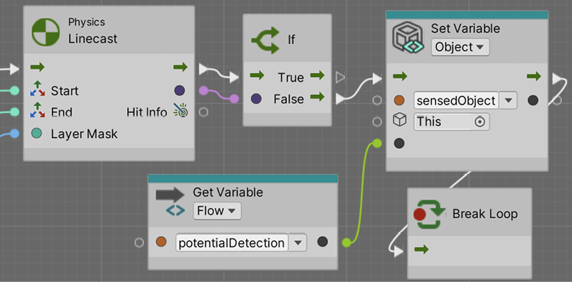
Figure 9.13: Setting the sensedObject
Again, pretty much self-explanatory; if the Linecast returns false, we set the potentialDetection variable (the currently iterated item) as the sensedObject variable (the one that will be accessed by other scripts later to query which is the object our AI can see right now). Something to consider here is the usage of the Break Loop node, which is the equivalent to the C# break keyword; essentially, we are stopping the Foreach loop we are currently in.
Now, even if we have our sensor working, sometimes checking whether it’s working or configured properly requires some visual aids we can create using gizmos.
Debugging with gizmos
As we create our AI, we will start to detect certain errors in edge cases, usually related to misconfigurations. You may think that the player falls within the sight range of the enemy but maybe you cannot see that the line of sight is occluded by an object, especially as the enemies move constantly. A good way to debug those scenarios is through editor-only visual aids known as Gizmos, which allow you to visualize invisible data such as the sight distance or the Linecasts executed to detect obstacles.
Let’s start seeing how to create Gizmos drawing a sphere representing the sight distance by doing the following:
- In the
Sightscript, create an event function calledOnDrawGizmos. This event is only executed in the editor (not in builds) and is the place Unity asks us to drawGizmos. - Use the
Gizmos.DrawWireSpherefunction, passing our position as the first parameter and the distance as the second parameter to draw a sphere in our position with the radius of our distance. You can check how the size of theGizmochanges as you change the distance field:

Figure 9.14: Sphere Gizmo
- Optionally, you can change the color of the gizmo, setting
Gizmos.colorprior to calling the drawing functions:

Figure 9.15: Gizmos drawing code
Now you are drawing Gizmos constantly, and if you have lots of enemies, they can pollute the scene view with too many Gizmos. In that case, try the OnDrawGizmosSelected event function instead, which draws Gizmos only if the object is selected.
- We can draw the lines representing the cone using
Gizmos.DrawRay, which receives the origin of the line to draw and the direction of the line, which can be multiplied by a certain value to specify the length of the line, as in the following screenshot:

Figure 9.16: Drawing rotated lines
- In the screenshot, we used
Quaternion.Eulerto generate a quaternion based on the angles we want to rotate. A quaternion is a mathematical construct to represent rotations; please search for this term for more info on it. If you multiply this quaternion by a direction, we will get the rotated direction. We are taking our forward vector and rotating it according to the angle field to generate our cone vision lines.
Also, we multiply this direction by the sight distance to draw the line as far as our sight can see; you will see how the line matches the end of the sphere this way:

Figure 9.17: Vision angle lines
We can also draw the Linecasts, which check the obstacles, but as those depend on the current situation of the game, such as the objects that pass the first two checks and their positions, we can use Debug.DrawLine instead, which can be executed in the Update method. This version of DrawLine is designed to be used in runtime only. The Gizmos we saw also execute in the editor. Let’s try them the following way:
- First, let’s debug the scenario where
Linecastdidn’t detect any obstacles, so we need to draw a line between our sensor and the object. We can callDebug.DrawLinein theifstatement that callsLinecast, as in the following screenshot:

Figure 9.18: Drawing a line in Update

Figure 9.19: Line toward the detected Object
- We also want to draw a line in red when the sight is occluded by an object. In this case, we need to know where the
Linecasthit, so we can use an overload of the function, which provides anoutparameter that gives us more information about what the line collided with, such as the position of the hit and the normal and the collided object, as in the following screenshot:

Figure 9.20: Getting information about Linecast
Note that Linecast doesn’t always collide with the nearest obstacle but with the first object it detects in the line, which can vary in order. If you need to detect the nearest obstacle, look for the Physics.Raycast version of the function.
- We can use that information to draw the line from our position to the hit point in
elseof theifsentence when the line collides with something:

Figure 9.21: Drawing a line if we have an obstacle

Figure 9.22: Line when an obstacle occludes vision
Regarding the Visual Scripting version, the first part will look like this:

Figure 9.23: Drawing Gizmos with Visual Scripting
Then, the angle lines would look like this:

Figure 9.24: Drawing Angle lines of sight in Visual Scripting
Note that, here, we are showing just one, but the other is essentially the same but multiplying the angle by -1. Finally, the red lines towards the detected object and obstacles will look like this:
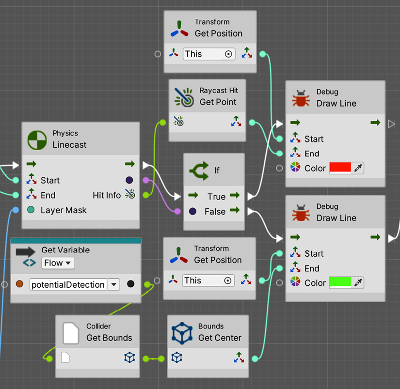
Figure 9.25: Drawing lines towards obstacles or detected objects in Visual Scripting
Note that, to accomplish this last one, we needed to change the previous Linecast node for the version that returns Raycast Hit info at the end.
With all of that, in this section, we created the sensors system that will give sight to our AI and plenty of info about what to do next. Now that we have our sensors completed, let’s use the information provided by them to make decisions with FSMs.
Making decisions with FSMs
We explored the concept of Finite State Machines (FSMs) in the past when we used them in the Animator component. We learned that an FSM is a collection of states, each one representing an action that an object can be executing at a time, and a set of transitions that dictates how the states are switched. This concept is not only used in animation but in a myriad of programming scenarios, and one of the common ones is AI. We can just replace the animations with AI code in the states and we have an AI FSM.
In this section, we will examine the following AI FSM concepts:
- Creating the FSM in C#
- Creating transitions
- Creating the FSM in Visual Scripting
Let’s start by creating our FSM skeleton.
Creating the FSM in C#
To create our own FSM, we need to recap some basic concepts. Remember that an FSM can have a state for each possible action it can execute and that only one can be executed at a time.
In terms of AI, for example, we can be patrolling, attacking, fleeing, and so on. Also, remember that there are transitions between states that determine conditions to be met to change from one state to another, and in terms of AI, this can be the user being near the enemy to start attacking or life being low to start fleeing. In the next figure, you can find a simple reminder example of the two possible states of a door:
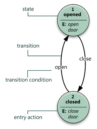
Figure 9.26: FSM example
- There are several ways to implement FSMs for AI; you can even use the
Animatorcomponent if you want to or download some FSM system from the Asset Store. In our case, we are going to take the simplest approach possible, a single script with a set ofIfsentences, which can be basic but is still a good start to understanding the concept. Let’s implement it by doing the following: - Create a script called
EnemyFSMin theAIchild object of the enemy. - Create an
enumcalledEnemyStatewith theGoToBase,AttackBase,ChasePlayer, andAttackPlayervalues. We are going to have those states in our AI. - Create a field of the
EnemyStatetype calledcurrentState, which will hold the current state of our enemy:

Figure 9.27: EnemyFSM state definition
- Create three functions named after the states we defined.
- Call those functions in
Updatedepending on the current state:

Figure 9.28: If-based FSM
Yes, you can totally use a switch here, but I just prefer the regular if syntax for this example.
- Test in the editor how changing the
currentStatefield will change which state is active, seeing the messages being printed in the console:

Figure 9.29: State testing
As you can see, it is a pretty simple but totally functional approach. In the future, you could face having to code enemies with many more states, and this approach will start to scale badly. In such a case, you could use any FSM plugin of the Asset Store you prefer to have more powerful and scalable tools, or even consider advanced techniques like Behavior Trees, but that’s outside the scope of this book. Now let’s continue with this FSM, creating its transitions.
Creating transitions
If you remember the transitions created in the Animator Controller, those were basically a collection of conditions that are checked if the state the transition belongs to is active. In our FSM approach, this translates simply as If sentences that detect conditions inside the states. Let’s create the transitions between our proposed states as follows:
- Add a field of the
Sighttype calledsightSensorin our FSM script, and drag the AIGameObjectto that field to connect it to theSightcomponent there. As the FSM component is in the same object asSight, we can also useGetComponentinstead, but in advanced AIs, you might have different sensors that detect different objects, so I prefer to prepare my script for that scenario. You should pick the approach you like the most. - In the
GoToBasefunction, check whether the detected object of theSightcomponent is notnull, meaning that something is inside our line of vision. If our AI is going toward the base but detects an object in the way, we must switch to theChasestate to pursue the player, so we change the state, as in the following screenshot:

Figure 9.30: Creating transitions
- Also, we must change to
AttackBaseif we are near enough to the object that must be damaged to decrease the base life. We can create a field of theTransformtype calledbaseTransformand drag the player’s base life object we created previously there so we can check the distance. Remember to add a float field calledbaseAttackDistanceto make that distance configurable:

Figure 9.31: GoToBase transitions
- In the case of
ChasePlayer, we need to check whether the player is out of sight to switch back to theGoToBasestate or whether we are near enough to the player to start attacking it. We will need another distance field calledPlayerAttackDistance, which determines the distance to attack the player, and we might want different attack distances for those two targets. Consider an early return in the transition to prevent gettingnullreference exceptions if we try to access the position of the sensor detected object when there are not any:

Figure 9.32: ChasePlayer transitions
- For
AttackPlayer, we need to check whether the player is out of sight to get back toGoToBaseor whether it is far enough to go back to chasing it. You will notice how we multipliedplayerAttackDistanceto make the stop-attacking distance a little bit greater than the start-attacking distance; this will prevent switching back and forth rapidly between attacking and chasing when the player is near that distance.
You can make it configurable instead of hardcoding 1.1:

Figure 9.33: AttackPlayer transitions
- In our case,
AttackBasewon’t have any transition. Once the enemy is near enough to the base to attack it, it will stay like that, even if the player starts shooting at it. Its only objective once there is to destroy the base. - Remember you can use
Gizmosto draw the distances:

Figure 9.34: FSM Gizmos
- Test the script by selecting the AI Object prior to clicking play and then move the player around, checking how the states change in the inspector. You can also keep the original
printmessages in each state to see them changing in the console. Remember to set the attack distances and the references to the objects. In the screenshot, you can see the settings we use:
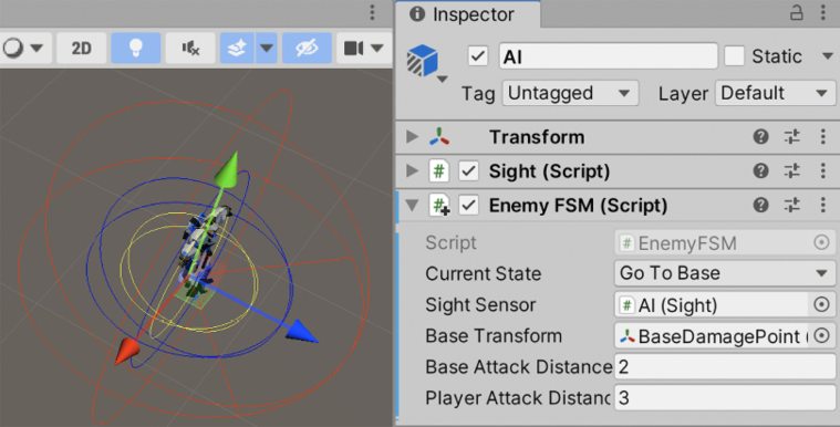
Figure 9.35: Enemy FSM settings
A little problem that we will have now is that the spawned enemies won’t have the needed references to make the distance calculations to the player’s base transform. You will notice that if you try to apply the changes on the enemy of the scene to the Prefab (Overrides -> Apply All), the Base Transform variable will say None. Remember that Prefabs cannot contain references to objects in the scene, which complicates our work here. One alternative would be to create BaseManager, a Singleton that holds the reference to the damage position, so our EnemyFSM can access it. Another one could be to make use of functions such as GameObject.Find to find our object.
In this case, we will see the latter. Even though it can be less performant than the Manager version, I want to show you how to use it to expand your Unity toolset. In this case, just set the baseTransform field in Awake to the return of GameObject.Find, using BaseDamagePoint as the first parameter, which will look for an object with the same name, as in the following screenshot.
You will see that now our wave-spawned enemies will change states:
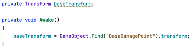
Figure 9.36: Searching for an object in the scene by name
Now that our FSM states are coded and execute transitions properly, let’s see how to do the same in Visual Scripting. Feel free to skip the following section if you are only interested in the C# version.
Creating the FSM in Visual Scripting
So far, most scripts in Visual Scripting were almost a mirror of the C# version with some differences in some nodes. While regarding state machines we could do the same, instead, we are going to use the State Machine system of Visual Scripting. The concept is the same, you have states and can switch them, but how the states are organized and when the transitions trigger is managed visually, in a similar way as the Animator system does. So, let’s see how we can use the system by creating our first State Machine Graph and some states. Follow these steps:
- Add the State Machine component to our enemy. Remember it is called State Machine and not Script Machine, the latter being the component for regular Visual Scripts.
- Click the New button in the component and select a place to save the
fixedasset in a similar way to what we have done so far for regular Visual Scripts. In my case, I called itEnemyFSM.

Figure 9.37: Creating a Visual State Machine
- Double-click State Machine Graph to edit it as usual.
- Right-click in any empty area of the Graph editor and select Create Script State in order to create a new state:

Figure 9.38: Creating our first Visual State Machine State
- Repeat step 4 until you end up having 4 states:

Figure 9.39: Visual states
- Select any of them and in the Info panel on the left, fill the Title field (the first one) with the name of any of the states we created before (
GoToBase,AttackBase,ChasePlayer, andAttackPlayer). If you don’t see the Info panel, click the button with the i in the middle to display it:

Figure 9.40: Renaming a Visual State
- Repeat that for the rest of the state nodes until you have each node named after each state created in the Creating the FSM in C# section of this chapter:
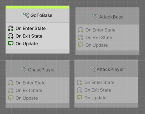
Figure 9.41: All needed states
- You can see one of the states has a green bar at the top, which represents which node is supposed to be the first one. I renamed that initial state
GoToBaseas that’s the one I prefer to be first. If you don’t have that one as the starting one, right-click the node that currently has the green bar in your state machine, select Toggle Start to remove the green bar from it, and then repeat for the node that you want to be the first one (GoToBasein our scenario), adding the green bar to that one.
Something to consider is that you can have more than one start state in Visual Scripting, meaning you can have multiple states running at the same time and transitioning. If possible, I recommend avoiding having more than one state active at a time to make things simple.
- Double-click
GoToBaseto enter the edit mode for these states. Connect a String node to the print Message input pin in the OnUpdate event node to print a message sayingGoToBase:

Figure 9.42: Our first state machine logic
- In the top bar, click the EnemyFSM label at the left of GoToBase in order to return to the whole State Machine view. If you don’t see it, click any text label at the right of the third button (the one that looks like <x>):
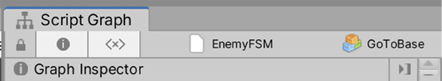
Figure 9.43: Returning to the State Machine editor mode
- Feel free to delete the other event nodes if you are not planning to use them.
- Repeat steps 9-11 for each state until all of them print their names.
With this, we have created the nodes representing the possible states of our AI. In the next section, we will be adding logic for them to something meaningful, but before that, we need to create the transitions between the states and the conditions that need to be met to trigger them by doing the following:
- Create variables in the Variables component of the enemy called
baseTransform,baseAttackDistance, andplayerAttackDistanceas we are going to need them to do the transitions. - Don’t set any type to
baseTransformas we will fill it later via code, but regardingbaseAttackDistance, make it using the Float type and put a value of2, and finally forplayerAttackDistance, also use Float and a value of3. Feel free to change those values if you prefer:
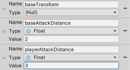
Figure 9.44: Variables needed for our transitions
- Right-click the
GoToBasenode and select the Make Transition option, and then click theChasePlayernode. This will create a transition between the two states:

Figure 9.45: A transition between two states
- Repeat step 3 for each transition we created in the C# version. The
State Machine Graphwill need to look like the following screenshot:

Figure 9.46: All the needed transitions
- Double-click the yellow shape in the middle of the transition between GoToBase and ChasePlayer to enter the Transition mode. Here, you will be able to specify the condition that will trigger that transition (instead of using an
Ifnode during the state logic). Remember you have two yellow shapes, one for each transition direction, so check you are double-clicking the correct one based on the white arrows connecting them. - Modify the graph in order to check if the
sensedObjectvariable is notnull. It should look like this:

Figure 9.47: Adding a transition condition

Figure 9.48: GoToBase to AttackBase transition condition

Figure 9.49: ChasePlayer to GoToBase transition condition
- For the ChasePlayer to AttackPlayer transition, do as in Figure 9.50. This is essentially the same as GoToBase and AttackBase, a distance check, but with different targets:

Figure 9.50: ChasePlayer to AttackPlayer transition condition
- For the AttackPlayer to ChasePlayer transition, do as in Figure 9.51. This is another distance check but is now checking if the distance is greater and multiplying the distance by
1.1(to prevent transition jittering as we explained in the C# version):
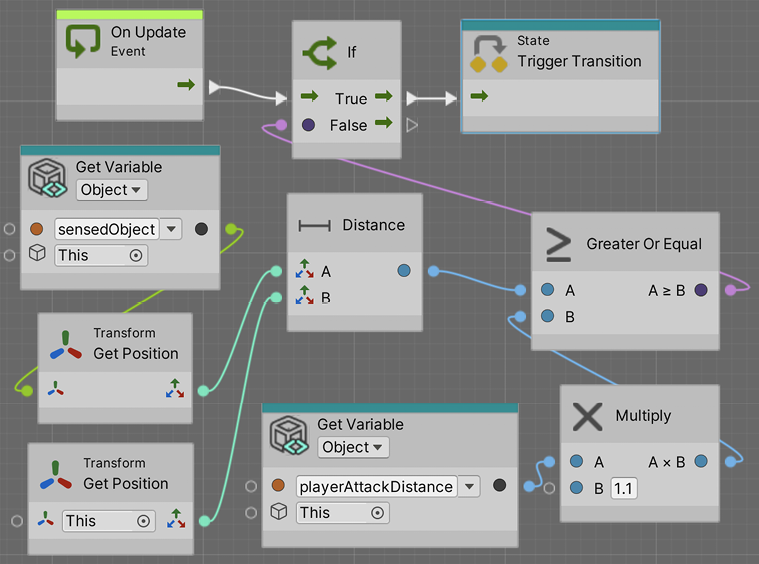
Figure 9.51: AttackPlayer to ChasePlayer transition condition

Figure 9.52: AttackPlayer to GoToBase transition condition
A little detail we need to tackle before moving on is the fact that we still don’t have any value set in the baseTransform variable. The idea is to fill it via code as we did in the C# version. But something to consider here is that we cannot add an Awake event node to the whole state machine, but just to the states.
In this scenario, we could use the OnEnterState event, which is an exclusive event node for state machines. It will execute as soon as the state becomes active, which is useful for state initializations. We could add the logic to initialize the baseTransform variable in the OnEnterState event node of the GoToBase state, given it is the first state we execute.
This way, GoToBase logic will look as in Figure 9.53. Remember to double-click the state node to edit it:

Figure 9.53: GoToBase initialization logic
Notice how, here, we set the result of the Find node into the variable only on the Null pin of Null Check. What Null Check does is check if our baseTransform variable is set, going through the Not Null pin if it is, and Null if it isn’t. This way we avoid executing GameObject.Find every time we enter the GoToBase state, but only the first time. Also, note that in this case, we will be executing the Set Variable node not only when the object initializes, but also each time GoToBase becomes the current state. If, in any case, that results in unexpected behavior, other options could be to create a new initial state that initializes everything and then transitions to the rest of the states, or maybe do a classic Visual Script graph that initializes those variables in the On Start event node.
With all this, we learned how to create a decision-making system for our AI through FSMs. It will make decisions based on the info gathered via sensors and other systems. Now that our FSM states are coded and transition properly, let’s make them do something.
Executing FSM actions
Now we need to complete the last step—make the FSM do something interesting. Here, we can do a lot of things such as shoot the base or the player and move the enemy toward its target (the base or the player). We will be handling movement with the Unity Pathfinding system called NavMesh, a tool that allows our AI to calculate and traverse paths between two points while avoiding obstacles, which needs some preparation to work properly.
In this section, we will examine the following FSM action concepts:
- Calculating our scene’s NavMesh
- Using Pathfinding
- Adding final details
Let’s start by preparing our scene for movement with Pathfinding.
Calculating our scene’s NavMesh
Pathfinding algorithms rely on simplified versions of the scene. Analyzing the full geometry of a complex scene is almost impossible to do in real time. There are several ways to represent Pathfinding information extracted from a scene, such as Graphs and NavMesh geometries. Unity uses the latter—a simplified mesh similar to a 3D model that spans all areas that Unity determines are walkable. In the next screenshot, you can find an example of NavMesh generated in a scene, that is, the light blue geometry:

Figure 9.54: NavMesh of walkable areas in the scene
Generating NavMesh can take from seconds to minutes depending on the size of the scene. That’s why Unity’s Pathfinding system calculates the NavMesh once in the editor, so when we distribute our game, the user will use the pre-generated NavMesh. Just like Lightmapping, NavMesh is baked into a file for later usage. Like Lightmapping, the main caveat here is that NavMesh objects cannot change during runtime. If you destroy or move a floor tile, the AI will still walk over that area. The NavMesh on top of that didn’t notice the floor isn’t there anymore, so you are not able to move or modify those objects in any way. Luckily, in our case, we won’t suffer any modification of the scene during runtime, but note that there are components such as NavMeshObstacle that can help us in those scenarios.
To generate NavMesh for our scene, do the following:
- Select any walkable object and the obstacles on top of it, such as floors, walls, and other obstacles, and mark them as Static. You might remember that the Static checkbox also affects Lightmapping, so if you want an Object not to be part of Lightmapping but to contribute to the
NavMeshgeneration, you can click the arrow at the left of the static check and select Navigation Static only. Try to limitNavigation StaticGameObjects to only the ones that the enemies will actually traverse to increaseNavMeshgeneration speed. Making the terrain navigable, in our case, will increase the generation time a lot and we will never play in that area. - Open the
NavMeshpanel in Window | AI | Navigation. - Select the Bake tab, click on the Bake button at the bottom of the window, and check the generated
NavMesh:

Figure 9.55: Generating a NavMesh
And that’s pretty much everything you need to do. Of course, there are lots of settings you can fiddle around with, such as Max Slope, which indicates the maximum angle of slopes the AI will be able to climb, or Step Height, which will determine whether the AI can climb stairs, connecting the floors between the steps in NavMesh, but as we have a plain and simple scene, the default settings will suffice.
Now, let’s make our AI move around NavMesh.
Using Pathfinding
For making an AI object that moves with NavMesh, Unity provides the NavMeshAgent component, which will make our AI stick to NavMesh, preventing the object from going outside it. It will not only calculate the path to a specified destination automatically but also will move the object through the path with the use of Steering behavior algorithms that mimic the way a human would move through the path, slowing down on corners and turning with interpolations instead of instantaneously. Also, this component is capable of evading other NavMeshAgent GameObjects running in the scene, preventing all of the enemies from collapsing in the same position.
Let’s use this powerful component by doing the following:
- Select the Enemy Prefab and add the
NavMeshAgentcomponent to it. Add it to the root object, the one calledEnemy, not the AI child—we want the whole object to move. You will see a cylinder around the object representing the area the object will occupy inNavMesh. Note that this isn’t a collider, so it won’t be used for physical collisions:

Figure 9.56: The NavMeshAgent component
- Remove the
ForwardMovementcomponent; from now on, we will drive the movement of our enemy withNavMeshAgent. - In the
Awakeevent function of theEnemyFSMscript, use theGetComponentInParentfunction to cache the reference ofNavMeshAgent. This will work similarly toGetComponent—it will look for a component in ourGameObject, but if the component is not there, this version will try to look for that component in all parents. Remember to add theusing UnityEngine.AIline to use theNavMeshAgentclass in this script:
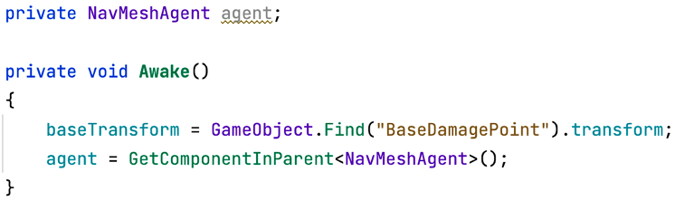
Figure 9.57: Caching a parent component reference
As you can imagine, there is also the GetComponentInChildren method, which searches components in GameObject first and then in all its children if necessary.
- In the
GoToBasestate function, call theSetDestinationfunction of theNavMeshAgentreference, passing the position of the base object as the target:

Figure 9.58: Setting a destination for our AI
- Save the script and test this with a few enemies in the scene or with the enemies spawned by the waves. You will see the problem where the enemies will never stop going toward the target position, entering inside the object, if necessary, even if the current state of their FSMs changes when they are near enough. That’s because we never tell
NavMeshAgentto stop, which we can do by setting theisStoppedfield of the agent totrue.You might want to tweak the base attack distance to make the enemy stop a little bit closer or further away:

Figure 9.59: Stopping agent movement
- We can do the same for
ChasePlayerandAttackPlayer. InChasePlayer, we can set the destination of the agent to the player’s position, and inAttackPlayer, we can stop the movement. In this scenario, Attack Player can go back again toGoToBaseorChasePlayer, so you need to set theisStoppedagent field tofalsein those states or before doing the transition. We will pick the former, as that version will cover other states that also stop the agent without extra code. We will start with theGoToBasestate:

Figure 9.60: Reactivating the agent

Figure 9.61: Reactivating the agent and chasing the player
- And finally, continue with
AttackPlayer:

Figure 9.62: Stopping the movement
- You can tweak the Acceleration, Speed, and Angular Speed properties of
NavMeshAgentto control how fast the enemy will move. Also, remember to apply the changes to the Prefab for the spawned enemies to be affected. - Regarding the Visual Scripting versions,
GoToBasewill look like the following screenshot:

- We deleted the OnUpdate event node printing a message as we don’t need it anymore. Also, we called the Set Destination node after setting the variable if
ifwasnull, and also when the variable wasn’tnull(Not Null pin of Null Check). Note that all of this happens in the On Enter State event, so we just need to do it once. We do it every frame in the C# version for simplicity but that’s actually not necessary, so we will take advantage of the OnEnterState event. We can emulate that behavior in the C# version if we want, executing these actions at the moment we change the state (inside theIfstatements that check the transition conditions), instead of using the Update function. Finally, notice how we needed to use the GetParent node in order to access theNavMeshAgentcomponent in the enemy’s root object? This is needed because we are currently in the AI child object instead. - Now, the AttackBase state will look like this:

Figure 9.64: Making our agent stop
- The ChasePlayer state will look like this:

Figure 9.65: ChasePlayer logic

Figure 9.66: AttackPlayer logic
Now that we have movement in our enemy, let’s finish the final details of our AI.
Adding the final details
We have two things missing here: the enemy is not shooting any bullets, and it doesn’t have animations. Let’s start with fixing the shooting by doing the following:
- Add a
bulletPrefabfield of theGameObjecttype to ourEnemyFSMscript and afloatfield calledfireRate. - Create a function called
Shootand call it insideAttackBaseandAttackPlayer:

Figure 9.67: Shooting function calls
- In the
Shootfunction, put similar code as that used in thePlayerShootingscript to shoot bullets at a specific fire rate, as in Figure 9.68. Remember to set the Enemy layer in your Enemy Prefab, if you didn’t before, to prevent the bullet from damaging the enemy itself. You might also want to raise the AI GameObject position a little bit to shoot bullets from a position other than the ground or, better, add ashootPointtransform field and create an empty object in the enemy to use as a spawn position. If you do that, consider making the empty object not be rotated so the enemy rotation affects the direction of the bullet properly:

Figure 9.68: Shoot function code
Here, you find some duplicated shooting behavior between PlayerShooting and EnemyFSM. You can fix that by creating a Weapon behavior with a function called Shoot that instantiates bullets and takes into account the fire rate and call it inside both components to re-utilize it.
- When the agent is stopped, not only does the movement stop but also the rotation. If the player moves while the enemy is being attacked, we still need the enemy to face the player to shoot bullets in its direction. We can create a
LookTofunction that receives the target position to look at and call it inAttackPlayerandAttackBase, passing the target to shoot at:

Figure 9.69: LookTo function calls
- Complete the
LookTofunction by calculating the direction of our parent to the target position. We access our parent withtransform.parentbecause, remember, we are the child AI object—the object that will move is our parent. Then, we set theYcomponent of the direction to0to prevent the direction from pointing upward or downward—we don’t want our enemy to rotate vertically. Finally, we set the forward vector of our parent to that direction so it will face the target position immediately. You can replace that with interpolation through quaternions to have a smoother rotation if you want to, but let’s keep things as simple as possible for now:

Figure 9.70: Looking toward a target
- Regarding the Visual Scripting version, AttackBase actions look like this:

Figure 9.71: AttackBase state
In this state, we have some things to highlight. First, we are using the LookAt node in the OnEnterState event node after the SetStopped node. As you might imagine, this does the same as we did with math in C#. We specify a target to look at (our base transform) and then we specify that the World Up parameter is a vector pointing upwards 0,1,0. This will make our object look at the base but maintain its up vector pointing to the sky, meaning our object will not look at the floor if the target is lower than him. We can use this exact function in C# if we want to (transform.LookAt); the idea was just to show you all the options. Also note that we execute LookAt only when the state becomes active—as the base doesn’t move, we don’t need to constantly update our orientation.
The second thing to highlight is that we used coroutines to shoot, the same idea we used in the Enemy Spawner to constantly spawn enemies. Essentially, we make an infinite loop between Wait For Seconds and Instantiate. We took this approach here because it was convenient given it takes fewer nodes in Visual Scripting.
Remember to select the OnEnterState node and check the Coroutine checkbox as we did before. Also, we need a new Float type variable called fireRate in the Enemy’s AI child object:
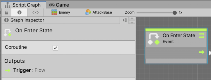
Figure 9.72: Coroutines
Then, AttackPlayer will look like this:

Figure 9.73: AttackPlayer state
Essentially it is the same as AttackBase, but that looks towards the sensedObject instead toward the player’s base, and we also made the LookAt node part of the infinite loop, to correct the enemy’s heading before shooting to target the player.
With that, we have finished all AI behaviors. Of course, these scripts/graphs are big enough to deserve some rework and splitting in the future, but with this, we have prototyped our AI, and we can test it until we are happy with it, and then we can improve this code.
Summary
I’m pretty sure AI is not what you imagined; you are not creating Skynet here, but we have accomplished a simple but interesting AI to challenge our players, which we can iterate and tweak to tailor to our game’s expected behavior. We saw how to gather our surrounding information through sensors to make decisions on what action to execute using FSMs and using different Unity systems such as Pathfinding to make the AI execute those actions. We used those systems to diagram a State Machine capable of detecting the player, running to them, and attacking them, and if the player is not there, just going to the base to accomplish its task to destroy it.
In the next chapter, we are going to start Part 3 of this book, where we will learn about different Unity systems to improve the graphics and audio aspects of our game, starting by seeing how we can create materials to modify the aspect of our objects and create Shaders with Shader Graph.