
Chapter 8: Animating Poses with IK Armatures
In the previous chapter, we explored how to use Layer Parenting to establish a parent-child relationship among the various layers in an Animate document. This helps us create a type of rig that we can use to animate a character's body parts with ease.
In this chapter, we will explore animating with Inverse Kinematics workflows by using fully rigged IK Armatures. Armatures in Animate are established by creating IK Bones using the Bone tool and exist on a single Armature Layer. We will build a multi-object armature and explore the various properties associated with each node to establish a solid and refined rig. We will then explore how Poses are managed by creating animation through Inverse Kinematics. Finally, we will learn how to package a rig for sharing and reuse.
After reading this chapter, you'll be able to do the following in Animate:
- Use the Bone tool to establish a rig and understand the concepts behind inverse kinematics.
- Adjust node properties such as joint constraints and physics on the established IK rig.
- Create animated IK content and manage rig poses across the timeline.
- Export a completed rig through the Animate Asset file type for sharing and reuse.
Technical Requirements
You will need the following software and hardware to complete this chapter:
- Adobe Animate 2022 (version 22.0 or above).
- Please refer to the Animate system requirements page for hardware specifications: https://helpx.adobe.com/animate/system-requirements.html.
Building an Armature using Inverse Kinematics
Previously, we learned how to animate a character across layers with Layer Parenting mechanisms using Advanced Layers mode. While they are simple enough to use, there are some limitations to consider while constructing your rig using that method, and dealing with so many layers can be a chore. Another rigging mechanism exists in Animate that is capable of similar results, but with a completely different workflow and set of tools. Animate is capable of producing animation through an Inverse Kinematics workflow by using the Bone tool and special armature layers. This will be the focus of the current chapter.
First, we'll address how these two approaches differ from one other and then build a rig using inverse kinematics.
Understanding Inverse Kinematics vs. Forward Kinematics
Just like in the previous chapter, we'll be using the wooden doll artwork to construct our alternate rig. As with all the files referenced in this book, you can locate this file at https://github.com/PacktPublishing/Adobe-Animate-2022-for-Creative-Professionals-Second-Edition.
Tip
If you would like to see the animation that we will create using IK, you can always open the Animated_WoodenDoll.fla file and perform a Test Movie to see it in action before we get to work! Just remember to close it before moving on.
Locate the WoodenDoll.fla file and open it within Animate. Just as in the previous chapter, there are two layers within this document: the Room layer, which is simply a background image, and the Doll layer, which contains a set of body parts that comprise our wooden doll.
Take a moment and refamiliarize yourself with these assets:
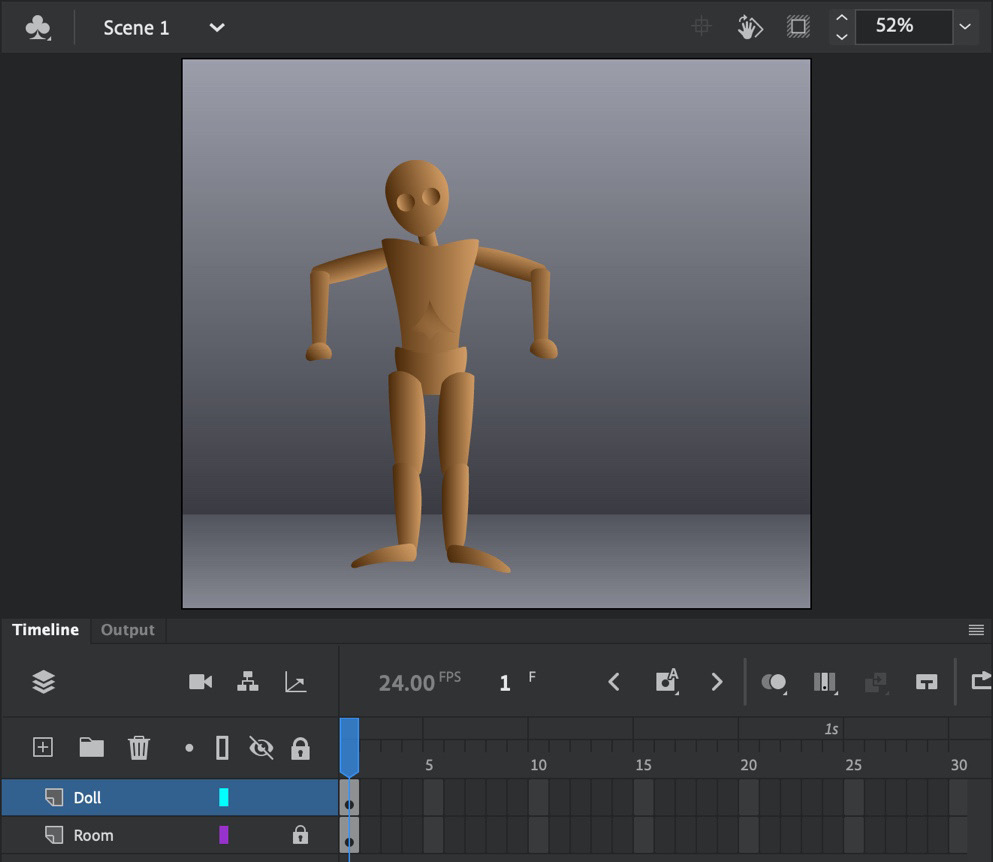
Figure 8.1 – The wooden doll starter document
Both Layer Parenting and Inverse Kinematics share several aspects. For instance, either one can be used effectively to produce complex, jointed character animation.
Layer Parenting is by far the simpler workflow to adopt as you have control over each object, and changing the properties of any object will not affect any additional object, so long as it is not a designated child of the modified object. It is easier to understand for beginners since layers are retained and animation takes place through normal tweening mechanisms.
Inverse Kinematics is a more complex approach as there are many more aspects to consider and tools to master. Alongside the technical aspects, modifying any object along the chain will have an immediate effect on the entire armature rig, affecting even the parent objects physically. More thought has to be put into every aspect of armature rigging since each piece directly influences the other objects making up the armature, and they can all have specific physical properties applied to them that differ from other parts of the rig.
Let's go ahead and compare both of these models, point by point.
Aspects of Layer Parenting
We learned how to use Layer Parenting in detail in Chapter 7, Character Design through Layer Parenting. This type of animation is sometimes referred to as Forward Kinematics, as you change the rotation and position of each joint from the top down. When animating an arm to wave at the viewer, for instance, you would begin by rotating the upper arm, then the lower arm, and finally the hand.
Keep the following aspects of layer parenting in mind:
- It works across many layers through parent-child relationships.
- Manipulating a child object will never influence a parent object.
- It is wholly controlled through Parenting View on the timeline, along with the Free Transform tool.
- It lacks any sort of constraint mechanism.
- It requires Advanced Layers mode to be activated.
- It makes use of normal tweening mechanisms to achieve motion.
Aspects of Inverse Kinematics
Inverse kinematics allows you to create a skeletal structure known as an armature, which is then animated as a single object that's influenced by a set of physics-based parameters that make use of various Poses over time. This is the primary subject of this chapter. When you're animating an arm to wave at the viewer, you could begin by manipulating any aspect of the arm as rotating the upper or lower arm will influence the other part. You must be very careful!
To implement the various aspects of inverse kinematics with those of layer parenting, consider the following:
- It works on a single, special layer type known as an Armature Layer.
- Manipulating a child object has a physical influence over the angle and rotation of the parent objects.
- It is controlled through special tools that can be accessed from the toolbar, such as the Bone tool, in addition to the Free Transform tool, the management of Poses within an Armature layer, and special bone properties through the Properties panel.
- It lets you constrain aspects of each joint by rotation, position, and more.
- It can be used with either Basic Layers mode or Advanced Layers mode.
- It makes use of special pose mechanisms, along with individual physical properties, to achieve resultant motion through Spring properties.
This information should provide some general ideas regarding the differences that are inherent between both rigging models. We are intentionally using the same assets across both this and the previous chapter to make the best comparison possible between rigging models.
With this background information around both models fresh in our minds, let's move on to rigging using Inverse Kinematics and the Bone tool.
Using the Bone Tool to Rig Symbol Instances
The Bone tool is the tool within Animate that we use to create Inverse Kinematics (IK) armatures from either a collection of symbol instances or simpler vector shapes, depending on our needs. First, let's explore how to use this tool with a collection of symbol instances, as arranged within the sample document.
To access the Bone tool, you will likely need to edit the available tools by utilizing the Drag and Drop Tools panel.
You can open this panel by clicking the Edit Toolbar… button at the bottom of the toolbar:

Figure 8.2 – Locating the Bone tool
The Bone tool and its associated Bind tool are located together, toward the bottom of the panel. Drag them onto the toolbar to make them available for working with your document.
Note
The Bone tool does not include any Tool properties that can be accessed from the Properties panel. You must create an armature first before setting various properties associated with IK.
You can use the Bone tool to construct an IK rig from separate symbol instances by placing bones across the individual body parts of the wooden doll:

Figure 8.3 – The Bone tool
This action will connect all the associated parts as a single Armature and also act as a complete rig that can then be adjusted and animated.
You can use the Bone tool by dragging an initial root "tail" bone, followed by additional bones that branch off from the root, to assemble a rough IK structural rig. Think of the rig as a tree, starting with the trunk and then expanding from that across branches and roots. The various bones and joints can then have their properties adjusted through the Properties panel, which creates a more refined IK rig for use.
Tip
When you're using the Bone tool, I highly recommend that you disable snapping entirely. This can be achieved through the application menu by choosing View | Snapping | Edit Snapping… and unchecking all the options shown in the dialog box that appears.
Now, let's look at the Bone tool in action as we create an IK rig for our wooden doll:
- Ensure that the Bone tool is selected in the toolbar.
- Click the top center of the doll's torso and drag a bone up to the neck area. Release your mouse to establish your initial "tail" bone:

Figure 8.4 – Creating the tail bone connecting the torso and the head
As you start creating additional bones, note how the tail bone of your rig has a slightly different appearance than any other bone you create.
- It is now possible to click and drag from the origin point of the tail bone to create additional bones. Click and drag a bone from the torso to the upper left arm, at the shoulder. A secondary bone will be created.
- From the shoulder of the upper left arm, drag another bone to the elbow of the lower left arm:
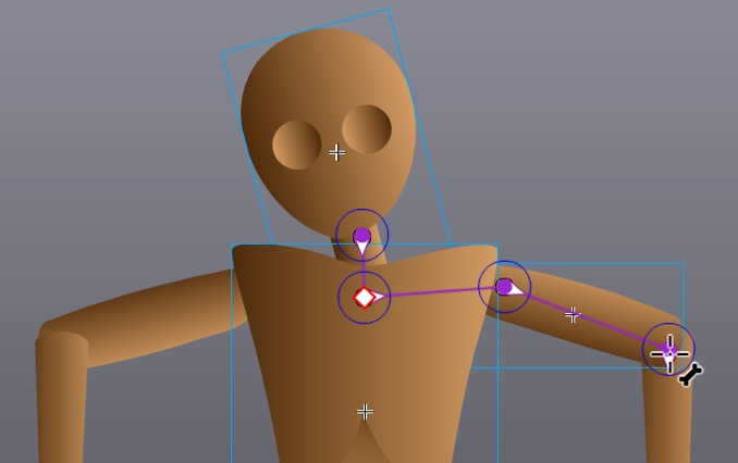
Figure 8.5 – Branching the bones from the initial tail across the arms
- Complete the arm branch by dragging a final bone from the elbow to the wrist.
- Now, you'll need to create additional branches until the entire rig is established:

Figure 8.6 – Fully rigged rough IK armature
The fully rigged armature should include the following:
- A branch from the torso to the head
- Branches across both the right and left arms
- A branch from the torso down to the pelvis
- Secondary branches from the pelvis down the left and right legs
Tip
If you have trouble dragging bones to the correct symbol instances to connect them, you can either rearrange things so that the Armature_1 layer appears below the existing Doll layer or arrange the various instances so that the one you need is not obscured by any other.
Notice that as you go through the process of creating your IK rig, the individual instances from the original Doll layer are removed from that layer and merged with the automatically created Armature_1 layer as they are added to the armature itself.
The previous layer has been completely removed:

Figure 8.7 – Newly created armature layer
An Armature layer is a special type of layer in Animate that is only used with IK rigging. The keyframes appear as small black diamonds, very similar to what we've seen with motion layers in the past. The layer icon changes to show a human figure in motion and the frame span's background becomes green.
With our IK armature created in this initial state, next, we will establish some refinements for the rig, ensuring that it will behave the way we want it to during manipulation.
Refining the Rig Properties
Once an armature has been created, the Selection tool can be used to modify the appearance of the armature by moving its various body parts around. In its initial, rough state, you can get some rather odd results before you start adding constraints and other refinements.
Using the Selection tool, click and drag the arms of the armature to create a different pose:
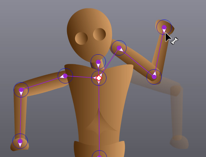
Figure 8.8 – Adjusting unconstrained armature limbs
This isn't very good! The joints have no constraints, so the arms bend around in unnatural ways. In addition, the arm can fly away from the shoulder altogether, making a real mess of our hard work.
A lot of beginners will simply rig up their assets with the Bone tool and think that's all there is to it. It is worth taking the time to inspect the properties of both the IK armature itself and also the individual IK Bone properties. We'll go ahead and do this now.
First, let's look at the IK Armature properties. The armature is bound to the layer, so you'll want to click on any of the frames that make up that layer and refer to the Frame tab of the Properties panel:
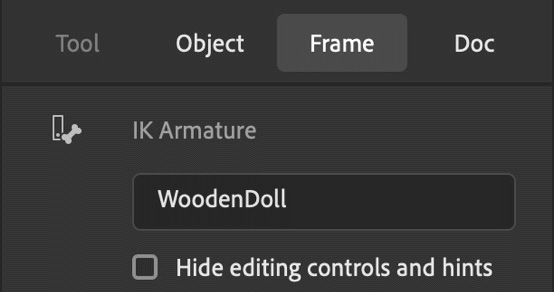
Figure 8.9 – The armature's Frame properties
You'll immediately notice that you are editing IK Armature properties. We can provide a meaningful name to our armature here and choose to hide or reveal editing controls and hints that overlay the armature itself on the stage.
Looking further down, you'll find the Ease section:
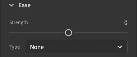
Figure 8.10 – The armature's Ease properties
The Ease properties consist of a Strength slider, which accepts values from -100 to 100 and defaults to 0. This is just like the easing intensity values we've seen in some of the various tween types covered in previous chapters.
You can also select the type of ease from the Ease Type dropdown. This is similar to selecting an ease effect as part of a Classic tween or Shape tween and the options include None, Simple, and Stop and Start. Each of these two choices has four versions: Slow, Medium, Fast, and Fastest. By default, None is selected.
I'm going to set my Ease properties to a Strength of -40 and use Simple (Medium) for my Type selection. This will provide some weight to the actual motion that's created between the poses of this armature.
We will also find an Options section further down the Properties panel:
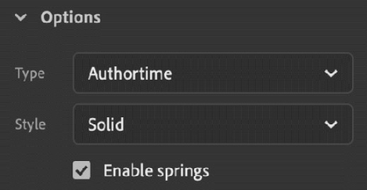
Figure 8.11 – The armature's Options
From here, you can define your armature to have an animation type of Authortime or Runtime. Authortime allows you to use the tools within Animate to design the motion of our IK armature, while Runtime makes it so that you can change poses by interacting with the armature at runtime by using the mouse cursor.
Note
Runtime armatures are only available when you're using ActionScript-based document types targeting Flash Player or AIR.
The Armature Style setting determines how the bone overlays appear on the stage as you modify the armature. The default setting is Solid, but you can also set this to Wire, Line, or None. This setting does not affect any functionality and is purely a personal preference as to how the various overlay controls appear. I tend to keep mine set to Solid.
The last setting in this section is a checkbox that allows you to Enable springs when selected or disable springs when deselected. Springs are attributes of individual IK Bones, and I suggest leaving this enabled for most armatures. We will go into more detail regarding this feature when we look at individual bone properties.
To view properties specific to any individual bone, use the Selection tool and click on the bone itself, not the underlying asset, to select it.
An unselected bone will appear in violet, and a selected bone will be shown in light green:
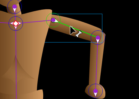
Figure 8.12 – Bone selection
With a bone selected, we can now explore the IK Bone properties. Note that in some of the screenshots, we've hidden the Room layer to focus on the individual bones and related controls.
Be sure that the bone is still selected and go to the Object tab of the Properties panel to view the IK Bone properties for the selected bone:

Figure 8.13 – IK Bone properties
The first thing you'll want to do is rename each bone in a way that makes sense. I've selected the bone that is aligned to the upper left arm, so I have named the bone LeftUpperArm. Similar to the overall IK Armature properties we saw earlier, we can also choose to hide or reveal editing controls and hints directly from each bone in this way. You will want to name every IK bone for organizational clarity.
At the bottom of the section, notice four buttons with directional arrows on them pointing left, right, up, and down. This is a navigational feature that lets you easily traverse the entire armature, bone to bone, by clicking these directional buttons instead of using the Selection tool to select each IK bone.
Tip
Depending on the structure of your armature, some of these directional buttons may be disabled. It all depends on the construction of your rig concerning the currently selected bone.
The Location section follows this and contains not just location properties, but several additional settings as well:
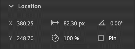
Figure 8.14 – Location properties
You can view the x and y positions of the bone from here, as the section header indicates, but you can also gauge the length of that IK Bone and its present angle. All of these settings cannot be adjusted from here; you need to interact with the armature directly for that.
There are also two settings here that can be manipulated. The little stopwatch icon indicates relative Speed and is measured from 0% to 100%. Modifying individual bone speed will provide additional variations of movement when the armature is animated. For instance, perhaps the upper arm moves more slowly than the lower arm because it is closer to the torso and doesn't have as far to travel.
The second setting is the Pin checkbox. Enabling this will lock an individual bone in place, freezing all movement. This ensures that the movement of your entire armature is not too wild and can be used to ground the entire armature in place while allowing movement through the other bones.
The Joint: Rotation section is very important for realistic movement:
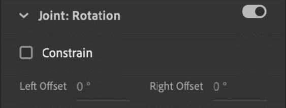
Figure 8.15 – Joint: Rotation properties
You can disable rotation entirely by toggling the switch in the top-right corner of this section to its off position, but it is often best to set angular constraints to each joint instead. If you enable the Constrain feature, you can set the angles of constraint through the Left Offset and Right Offset settings.
Since we are dealing with the upper arm, the joint in question is that of the shoulder. Without a constraint set, the arm can rotate all the way around; the same goes for the lower arm. That's not how the human body works at all!
We can see the constraints visually expressed on our armature as well:
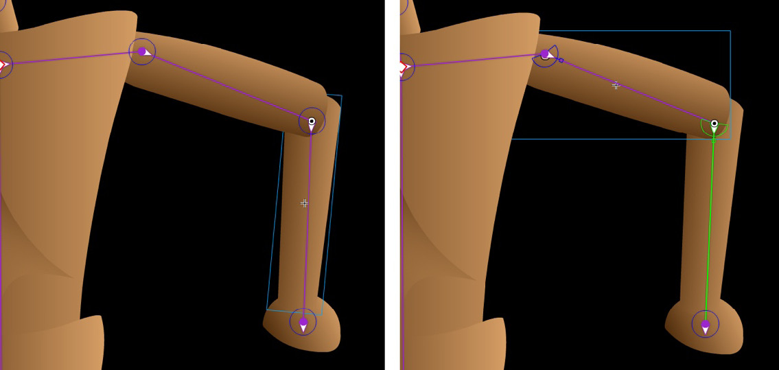
Figure 8.16 – The difference that proper rotation constraints make is huge
The left screenshot shows the initial state of our arm joints with no rotation constraints. The right screenshot shows a more refined rig, with angular constraints at both the shoulder and elbow. This will enable more natural poses for our armature. You will want to perform these constraints across all IK bones.
The next sections, Joint: X Translation and Joint: Y Translation, are both very similar to Joint: Rotation in practice:
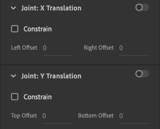
Figure 8.17 – Joint: X Translation and Joint: Y Translation properties
Unlike with Joint: Rotation, these settings are all toggled off by default and if you want to use them, you will need to hit the toggle switch. Translation refers to the amount of movement across a certain number of pixels across all four directions on both the x and y axes. This is not normally something that can be applied to a human figure such as this, but it is often used when rigging machinery. Think of the up and down movement of a set of engine pistons, for example. We won't be using this for our armature, but it's there in case you ever need it!
The final section has to do with Spring:
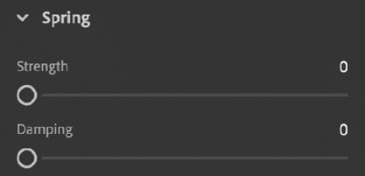
Figure 8.18 – Spring properties
As you may recall, we mentioned Spring earlier when we looked at the IK Armature properties. Spring provides a physical springiness to your motion, even after the object has come to rest. The greater the Strength property of Spring, the more residual movement will occur. Damping is a way to dampen or buffer Spring and determines how long it takes for the effects of Spring to lessen and finally dissipate. Think of a tree branch following a gust of wind and how the movement slowly winds down over time. This is what can be expressed through Spring.
Now that you know how to refine your IK Armature and IK bones by using these properties, you'll want to take some time to do so. Be sure to name each bone and set proper constraints where necessary, using the human form as a guide.
There are several tricks you can use when adjusting and testing your armature at this phase. Keep the following in mind as you refine your rig:
- Holding down the Shift key while adjusting your rig parts with the Selection tool will isolate joint rotation to that specific bone.
- Holding down Option/Alt as you click and drag body parts with the Selection tool will allow you to relocate assets while keeping the rig intact.
- You can even adjust the transform point of each part using the Free Transform tool to modify the joint's position.
- Don't forget to use the Arrange options as well to ensure the proper stacking order of the various parts.
When complete, change the name of the armature layer from Armature_1 to WoodenDoll. Be sure to save your .fla document as we'll be taking a slight detour in the next section before returning to our wooden doll.
Next, we'll have a brief look at using the Bone tool within shapes before moving on to IK animation.
Using Bone Tool to Rig Shapes
So far, we've built our armature out of a collection of symbol instances. We can also create an armature as part of a shape. It is worth going into this a little bit to close out this section before animating our previously created wooden doll armature.
Creating an IK armature with an IK shape is very similar to creating an IK Armature with Movie Clip symbol instances. The main difference is that you can build this using only a single shape object, while we previously made use of a set of different objects bound together using an IK armature.
Let's explore how to use inverse kinematics using a single shape:
- Create a new document of any size and use one of the shape tools to draw out a basic shape. I'm simply going to create a long, rounded rectangle for this example:

Figure 8.19 – Basic shape created
- Select Bone Tool and drag out a bone to one end of the shape, covering about one-fifth of the entire shape. This is the initial "tail" bone for your IK shape-based armature:

Figure 8.20 – Dragging the tail bone
- With the tail created, we can now drag out branching bones from this tail bone to create either a linear or multi-branch armature within the shape. Continue laying down additional bones across the IK shape until you reach the other end:

Figure 8.21 – Shape-based armature created
- At this point, the shape has been converted into a special type of object in Animate called an IK Shape and contains a complete armature. Using the Selection tool, drag one end of your armature around to see how the bones affect the shape itself:
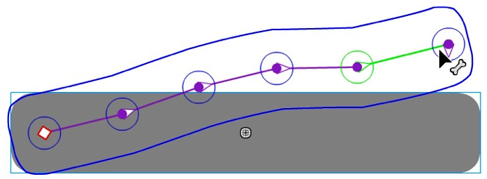
Figure 8.22 – Shape armature movement
The shape will morph along with the internal bone structure you've created.
Note
You can still refine this armature by using the IK Armature and IK Bone properties, such as joint rotation constraints, joint translation, and spring, which we examined previously. All these settings work the same, no matter what style of armature you create.
You may notice that as you modify the armature with the Selection tool, sometimes, the edges of the shape become odd. We can control such behavior by using the Bind tool, which we will cover in the next section.
Using Bind Tool to Refine Shapes
Only applicable to IK Armatures created with shapes, we can use the Bind tool to modify connections between existing bones and the shape control points that define the overall path. If you are having extreme and unwanted distortion in your shape as you adjust the armature, this tool can help you refine and eliminate these oddities.
The Bind tool is likely going to have to be added to the toolbar through the Edit Toolbar… button at the bottom of the Tools panel. If you didn't add this tool alongside the Bone tool earlier, you'll want to do this now.
Its appearance is similar to the icon for the Bone tool, but with an additional little target reticle alongside it:

Figure 8.23 – The Bind tool
The Bind tool is used for control point management within shape-based armatures.
If you select any IK bone in your armature, you will see the various control points attributed to that particular bone highlighted in yellow:
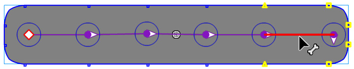
Figure 8.24 – Bone selected with the associated control points
Control points are the shape path anchor points but, within an IK armature, they are additionally associated with particular bones so that the overall shape can be morphed as the armature shifts around.
You can also select any control point to highlight any of the bones associated with that point by clicking a control point with the Bind tool selected. This gives you a good idea of which points are controlled by which bones.
To change control point associations, you can select a bone and then hold down the Shift key to select additional control points you want to associate with the selected bone. To remove associations, you can hold down Option/Alt and click any of the currently highlighted points.
Tip
Managing various control points and bone associations can help remedy any extreme morphing when dealing with IK shapes, although it can be very finicky to work with and we should be extra cautious when using this workflow.
In this section, we learned how to build IK armatures using the Bone tool and refined our armatures using the various properties and settings available. We explored the construction of armatures using both symbol instances and shapes and learned how to constrain joint rotation and translation to achieve a solid, capable rig. Next, we will explore how to create animation using our IK armature by using Poses.
Animating an IK Armature
Now that we have created our armature and refined its various properties, it's ready to be animated. The motion of an IK armature is not animated using any of the tweening methods we've seen up to this point. Instead, we can define various poses across the timeline and Animate will automatically fill in the frames between each pose. It can do this without creating any additional tween as the layer is already an Armature Layer, similar to how Motion Layers work when establishing a Motion Tween.
Let's define some additional poses so that we can animate the wooden doll figure jumping into the air.
Creating Additional Poses
Looking at the WoodenDoll Armature Layer as it is right now, there is a single pose at frame 1. A pose is signified by a small diamond shape along the timeline. As expressed previously, we can animate IK armatures by defining poses as various spots along the timeline. A pose behaves very similarly to a keyframe, except that a keyframe contains the properties for a single object, while a pose contains the properties for all the objects that make up your armature and is all handled through the single pose.
For this animation, we want our figure to jump into the air and then land again. We will require a set of four distinct poses for this animation to occur:
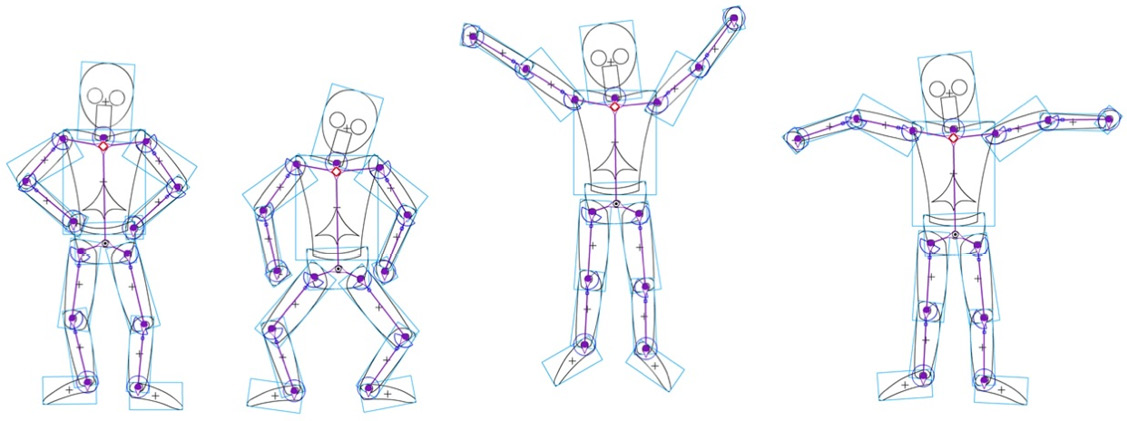
Figure 8.25 – The four necessary poses
You can think of the four poses in this way, and in this order:
- Resting: A pose where the figure is standing at a comfortable resting position.
- Anticipation: A crouching pose where the figure prepares to jump.
- Active: This is where the figure is up in the air, at the apex of an active jump.
- Recovery: The figure hits the ground and, from this point, can go back to the resting or anticipation poses, depending on how many times you'd like it to jump.
Let's go ahead and create these Poses now. You can refer to the previous figure of all four Poses as a visual guide:
- The first pose we need to create is our resting pose. This pose exists on frame 1 and, as shown within the timeline, the pose itself already exists:
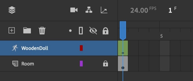
Figure 8.26 – The initial pose at frame 1
Use the Free Transform tool to position and rotate each of the body parts so that the pose appears similar to the resting example:
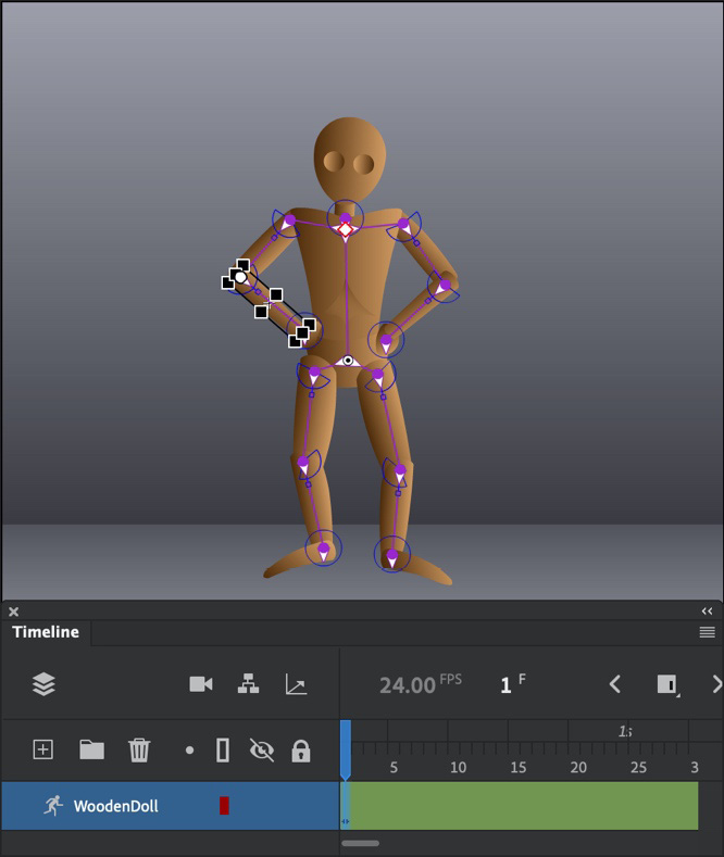
Figure 8.27 – The resting pose
- To create an animation, we need more than a single frame on the timeline. Extend the current frame span to the 3 second marker at frame 72 (assuming you have a 24 FPS document setting) so that we have a good amount of time to plot our poses across.
- Now, let's create our second pose. Recall that poses are represented by small diamond-shaped keyframes along the timeline. Move the playhead to frame 12 and use the Free Transform tool to adjust the various body parts so that the figure is crouching in preparation to jump, similar to the anticipation pose example:
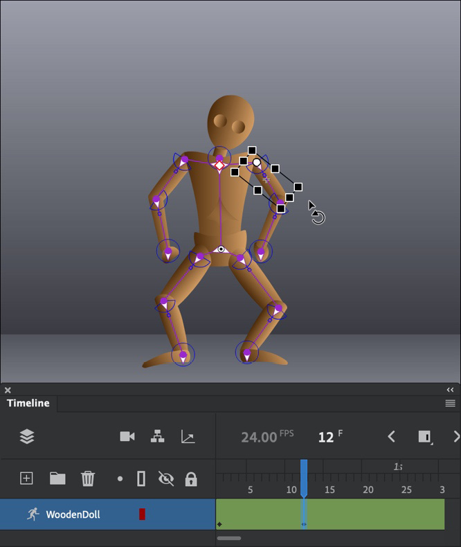
Figure 8.28 – The anticipation pose
With two poses established, scrub the playhead along the timeline and see how the figure animates automatically between each pose. Each time we add a new pose, the frames in-between the poses will update, just as though we were using a tween.
- Move the playhead to frame 18 to create a new arrangement representing the proposed action pose. Use the Free Transform tool to place the legs together and the arms stretched out wide. You'll also need to shift the armature's position higher on the stage to fully realize the jumping motion:
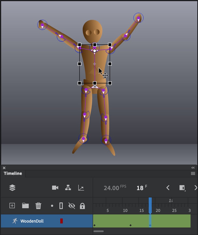
Figure 8.29 – The active pose
- The final pose represents the figure having jumped, now landing on the floor in a recovery position on frame 22. Ensure that the figure is securely planted on the floor by changing the armature's overall position. Using the Free Transform tool again, bring the arms down a bit and ensure that the feet and legs look appropriate concerning the floor beneath:
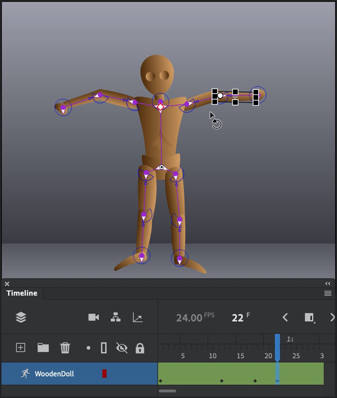
Figure 8.30 – The recovery pose
- Test your animation by playing it back with the timeline playback controls or through the Test Movie command.
If anything needs to be adjusted, you can go back and adjust the IK armature, the IK bones, or the individual poses to make everything as smooth and realistic as possible.
We now have a single jump cycle composed of four distinct poses, but we can go further than this! Let's learn how to manage the various poses we've established in different ways.
Managing Armature Poses
Once you have created your IK Armature poses, it is very simple to then copy and paste them wherever they're needed to produce a full animation. In this section, we'll refine our overall animation and reproduce the completed animation cycle for our wooden doll figure.
Since we've already created our various poses, it is now just a matter of arranging them at different points along the timeline:
- The first thing we want to do is place a hold on our initial resting animation for a few frames. Select the pose on frame 1 and right-click to summon the menu. Choose Copy Pose from the menu items that appear:
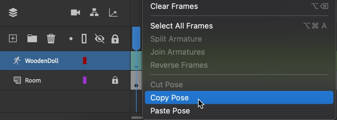
Figure 8.31 – Copying an existing pose
- Now, select frame 7 and right-click again. Choose Paste Pose from that same menu to create identical poses across these frames, essentially creating a pause in the action:
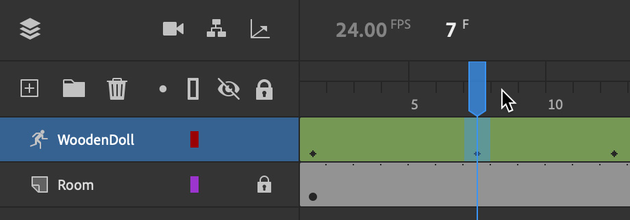
Figure 8.32 – The pasted pose creates a pause
- With the initial pose still present in the system clipboard, move to frame 25 and select it.
- Right-click once again and choose Paste Pose from the menu that appears. This will bring the wooden doll back to a resting position following the anticipation, action, and recovery poses. We now have a full animation cycle defined within our timeline.
- To repeat this cycle, we can copy and paste full spans of frames, including poses. Select frames 7 – 25:
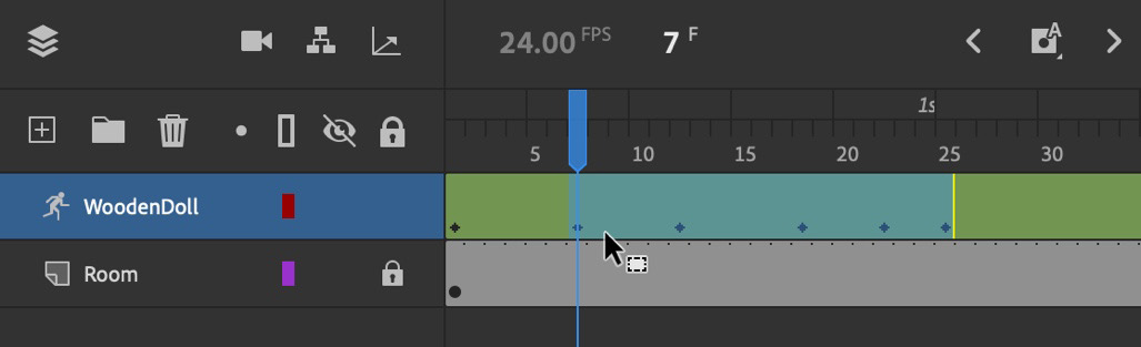
Figure 8.33 – Frame span selected to copy
Right-click to summon the contextual menu for frame selections.
- Choose Copy Frames from the menu that has appeared.
- Select frame 30 and summon the right-click menu once again.
- This time, select the Paste and Overwrite Frames option to paste the frame span without extending the overall timeline:
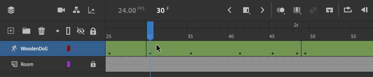
Figure 8.34 – The pasted frame span produces a repeated cycle
The frame span has been added to our existing animation cycle as a separate armature frame span and, upon playback, the figure jumps twice. Notice the vertical lines that appear as part of the layer. These indicate where each armature span begins.
Since we have multiple armature spans now, we can manage these armature spans through the frame selection right-click menu by choosing Join Armature or Split Armature.
You can now continue adding additional jump cycles in this way and even go back and tweak the various poses to add some variability to the entire animation. It's entirely up to you!
Note
You can also choose Clear Pose from the right-click menu on an existing pose, which will remove it from the timeline in its entirety. The Insert Pose option, which is right above Clear Pose, will insert a new pose at the selected frame manually.
In this section, we explored how to animate our IK armature using poses and how to manage those poses across the timeline. In the next section, we'll wrap this chapter up by examining how to share our carefully crafted rig as an Animate Asset.
Sharing a Completed IK Rig
While we can copy and paste frames and even entire layers from one document to another, it can be a bit cumbersome to do so and is very unorganized in practice. Animate comes equipped with a workflow for sharing rigged objects through Animate Asset (.ana) files.
Let's learn how to export these files to either preserve them in an organized way, share them with colleagues, or make them available as a persistent resource through the Assets panel.
Saving a Rig for Reuse
If you've created an IK armature and you'd like to save it so that you can use it on additional assets in the future, Animate has a workflow that can be used to generate your rig as an Animate Asset for sharing or for direct use from the Assets panel.
If we want to preserve our wooden doll armature as a rig, we need to wrap it within a symbol, as follows:
- Right-click on the WoodenDoll layer and choose Convert Layers to Symbol from the menu that appears.
- In the Convert Layers to Symbol dialog, name it WoodenDoll and choose Graphic as the symbol type:

Figure 8.35 – Converting your armature into a Graphic symbol
We are using a Graphic symbol so that the armature animation can be viewed within the authoring environment timeline. If we created a Movie Clip symbol, the only way to preview would be via Test Movie.
- When you're ready, click OK to perform the conversion. The full IK Armature layer will be wrapped within the symbol and an instance will be placed within the timeline, replacing the layer that was there previously:
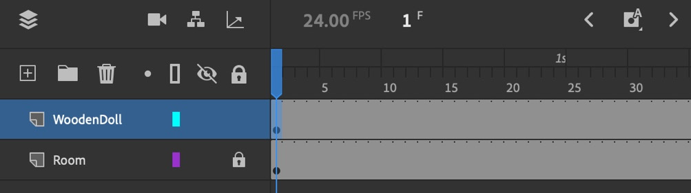
Figure 8.36 – The IK armature layer has been replaced
Once you have created your symbol with a fully rigged armature within it, locate the symbol you want to export as a rig from the Library panel. We'll use the Library panel to export our rig as an Animate Asset (.ana) file.
To export a symbol from our document to use as a sharable asset, perform the following steps:
- Select the symbol in the Library panel and open the menu by right-clicking it:

Figure 8.37 – Exporting an asset from the Library panel
You'll find two options here: Export Asset… and Save As Asset…. Either one will create the rig, but if we want to save to a .ana file, we'll need to choose Export Asset… and make a few selections in the dialog that follows.
- Once Export Asset… has been chosen, a dialog will open and present you with several options:
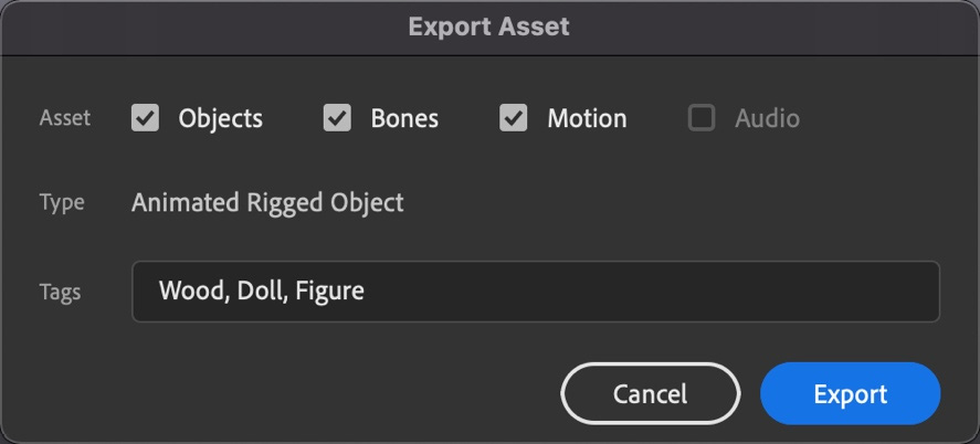
Figure 8.38 – Saving a rig for reuse as an Animate asset
These dialog options include providing the asset with a Name and choosing which aspects of the asset you want to include: Objects, Bones, Motion, or Audio. Only those aspects of the asset that are available for packaging can be chosen. As we have no audio, that option is not available.
Depending on your checkbox selections, the Type property of the asset to be saved will be displayed. In this case, I'm saving an Animated Rigged Object. You can also input a set of Tags here to help locate your asset once within the Assets panel through the integrated search mechanism.
- Click Export and save your asset as a .ana file:
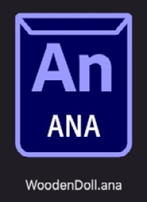
Figure 8.39 – An Animate Asset file
The Animate Asset now exists as a .ana file on your hard drive, which can now be distributed to others or added to your version of Animate through the Assets panel.
Next, you'll learn how to import a .ana file from your local filesystem into Animate.
Importing a Rig within the Assets Panel
Let's close out this chapter by importing the .ana file we created into our Assets panel for reuse. Of course, if the option to Save As Asset… was selected from the Library panel menu instead of Export Asset…, your asset would immediately be added to the Assets panel and no .ana file would be generated.
The first step of importing an exported Animate Asset file is to open your Assets panel and click the Custom tab:
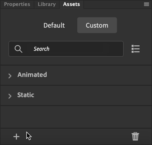
Figure 8.40 – Importing an Animate asset
Depending on whether you have added any assets previously, some may be present here; otherwise, your panel will be empty. There is a small button in the bottom-left corner of the panel that looks like a big plus symbol. This is the Import Assets button. Clicking this will open a file browser, which you can use to locate the .ana file you want to import.
Once you have chosen the file you want, it will be added to the appropriate category within the Assets panel:
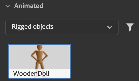
Figure 8.41 – Imported rigged object within the Assets panel
You should also perform a search from the panel based on the tags that were input when you exported the asset. Once imported, an asset such as this can be used across Animate documents as a persistent resource.
Note
You can also import assets by using the Assets panel options menu in the top-right corner by choosing Import. You can manage your custom assets through this menu since you have access to options such as Delete.
Aside from Rigged Objects, you can also save Rig alone, to be applied to existing artwork. Rigs can be included in the Custom tab of the Assets panel but are also available in the Default view. Rigs can be applied to existing artwork by using the Rig Mapping panel.
The Rig Mapping panel can be opened from the application menu by choosing Window | Rig Mapping. This panel will also open automatically when you're selecting a Rig for use within the Assets panel. This is because you must identify individual movie clip symbol instances to apply to specific bones of the rig armature:

Figure 8.42 – Locating Rigs within the Assets panel
To apply a Rig from the Assets panel to a symbol instance, you must double-click the instance to enter the symbol itself. Dragging and dropping a rig onto the stage will then open the Rig Mapping panel, where you can map certain visual elements, such as the torso, arms, legs, and so on, to the Rig itself.
You simply click each bone in the Rig Mapping panel and then choose individual movie clip symbol instances within the containing symbol to associate each bone with a symbol instance. This will allow the system to recreate the full armature:
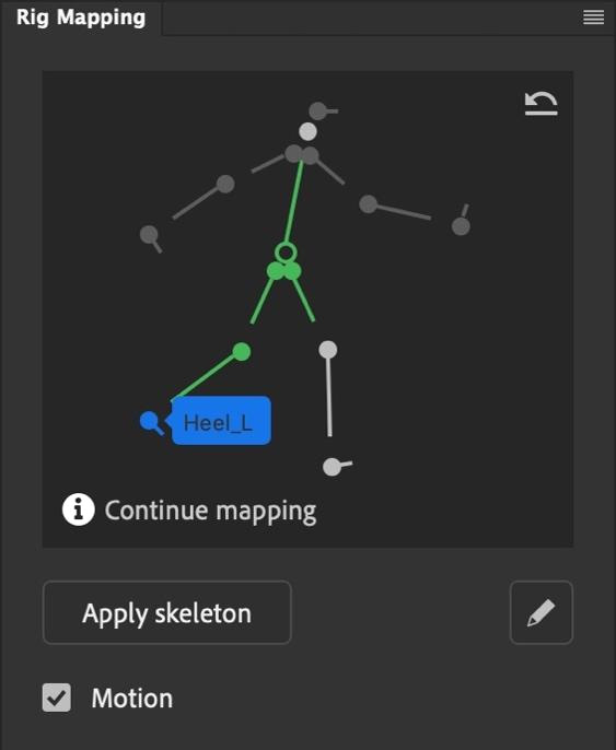
Figure 8.43 – Applying a pre-built rig
Be sure to start from the root node and then branch off from there. Rigged bones will appear green, while unrigged bones will appear gray.
Once you've mapped all the necessary visuals to the rig, choosing Apply skeleton will create an armature – with full animation if the Motion checkbox is selected – for your symbol instance.
Once a skeleton has been completely applied to a set of objects, Rig will appear pink.
Tip
There is also a way to automatically map a rig to your symbol instance and avoid the manual mapping process. For this to work, be sure that each of the movie clip symbol instances that make up your visuals include instance names that are identical to those from the rig itself. This method bypasses the visual Rig Mapping panel workflow altogether but is very specific.
In this section, we looked at how to preserve, share, and apply our IK armature rigs, motion, and assets by creating and using Animate Asset files. These files can be used to preserve important assets or share them with colleagues and the wider world!
Summary
In this chapter, we took a deep dive into one of the most mystifying workflows in all of Animate – Inverse Kinematics. This is truly a professional-level animation workflow and one that can easily be done incorrectly if you don't have a good understanding of all the different aspects involved in IK armatures, IK bones, poses, and the various settings attributed to each. You can now confidently rig an armature using inverse kinematics in a refined and believable way, as well as animate the character or figure attributed to your armature by creating and managing poses across the timeline.
In the next chapter, we are going to look at the most modern and flexible method of creating rigging for your animated content; that is, by using Warped Objects.