
8
Building Your Mule Application
In the previous chapter, we learned how to use DataWeave to transform data from one format to another.
In this chapter, let us explore the different configuration files available in a Mule application and try using different components, such as Schedulers, APIkit Router, and Object Store Connector, to build a Mule application. In Chapter 3, Exploring Anypoint Studio, we created and tested a simple Mule application, HelloWorld. In this chapter, we will be learning how to build a Mule application with different components elaborately.
After reading this chapter, you’ll come away with more knowledge on the following topics:
- Different configuration files in a Mule application
- How to create a Mule application with Schedulers
- How to create a Mule application with APIkit Router
- How to use Object Store Connector
Technical requirements
The prerequestive for this chapter are:
- Anypoint Platform, which we configured in Chapter 2, Designing Your API.
The link to log in is https://anypoint.mulesoft.com/login/.
- The musicbox-sys-api.raml RAML file required to create a Mule application is available on GitHub at the following link, under Chapter2:
https://github.com/PacktPublishing/MuleSoft-for-Salesforce-Developers
Exploring different types of configuration files
There are a few types of files that we will come across while developing a Mule application. Each file has its own purpose. The files are as follows:
- Mule configuration file
- Properties file
- Project Object Model – a pom.xml file
- API Specification file (Open API Specification and RAML)
We already learned about API Specification in Chapter 2, Designing Your API.
Let’s begin by exploring the Mule configuration file.
Mule configuration file
A Mule configuration file is a .xml file that contains all the information related to Mule flows and connector configurations. Whenever we create a new Mule application project, it creates a Mule configuration file in the /src/main/mule folder in the Package Explorer. When you open the Mule configuration file, it opens in the editor, where you can see the following three tabs:
- Message Flow
- Global Elements
- Configuration XML
Message Flow contains the canvas, which helps with designing various flows. Canvas visually displays Muel flows. Inside the canvas, it is easy to drag and drop the required components from Mule Palette. Generally, a flow has two sections – Source and Processor – as you can see in the following figure:

Figure 8.1 – Message Flow
The HTTP Listener component is available inside the Source area. HTTP Listener is the way to listen for incoming HTTP requests to any application. The Logger and Transform Message components are available inside the Processor section.
Global Elements is the place where we maintain all the configuration elements that are required for the particular Mule project. In this tab, we can add, edit, and delete the required configuration data for different connectors (see Figure 8.2):
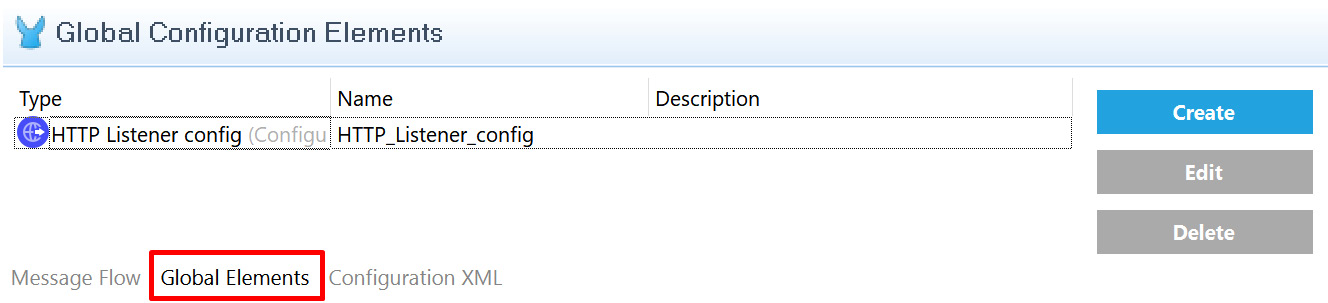
Figure 8.2 – Global Elements
Figure 8.2 shows HTTP Listener config in the Global Elements tab. This configuration will have details about the HTTP URL, port, and other required configurations for HTTP Listener. We can click the Create button to add other connector configurations, such as Salesforce and other systems.
Configuration XML, as shown in the following figure, is an XML file that contains the details of all the flows. In simple terms, the flow, which we design in the canvas, and the configuration in the global elements are written in XML:
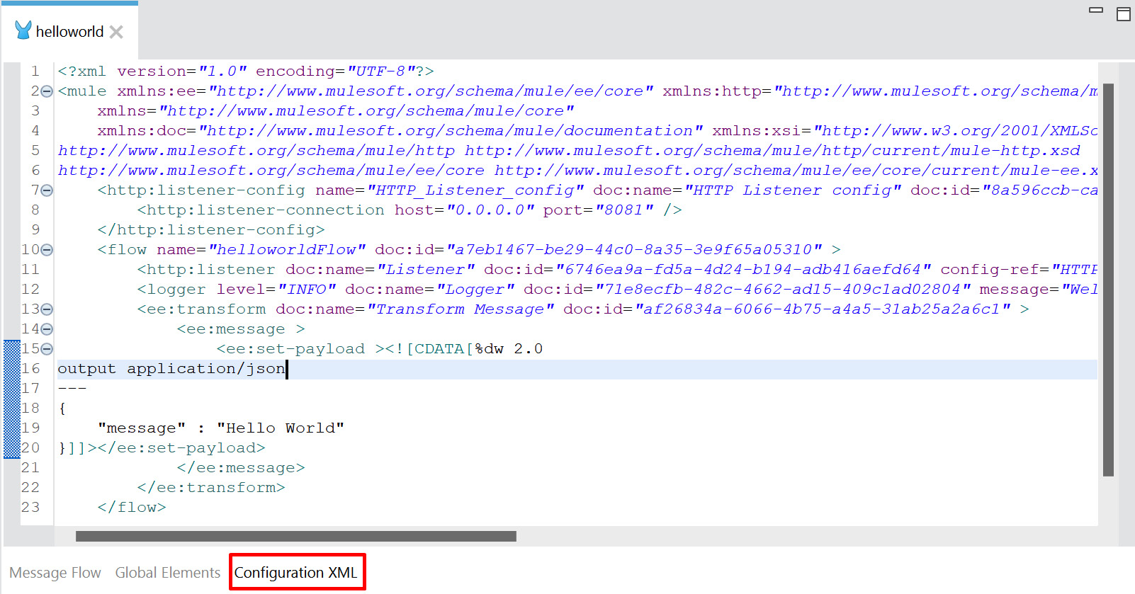
Figure 8.3 – Configuration XML
Figure 8.3 shows all the details of the flow, the HTTP Listener configuration, and the Transform Message configuration in XML format. These components come under the <flow>, <http-listener-config>, <ee:transform> tags/elements, respectively.
We can also directly edit the file to reflect the changes in the canvas.
With this, we have understood the list of tabs that are available in a Mule configuration file. Let’s move on to the properties file, where we define the environment-related configurations.
Properties file
We can store configurations in .properties or .yaml files. To avoid hard coding (keeping the values directly in the program), we can store the values such as URLs, port, credentials, and any application-specific configurations in properties file. It is located under the src/main/resources folder. We can also store specific entries or the entire file in encrypted format instead of plain text in order to secure the configuration. For instance, while connecting to Salesforce, we have different URLs and credentials for development, test, and production environments. In this case, it is always best practice to keep the configuration separate instead of having it in the code. We can have the development environment configuration in dev-properties.yaml, quality assurance (QA) environment configuration in qa-properties.yaml, and production environment configuration in prod-properties.yaml. So, in future, if there are any changes to the URL or credentials, it will be easy to update them in the properties file directly.
We can define the configuration in two different file formats:
- The .properties file, where the key and values are on the same line
- The .yaml file, which follows indentation (syntax with few spaces) to store the key and values
The configuration data can be either plain or encrypted text. Let’s see a few examples for better understanding. We can use the Secure Properties tool to generate the data in an encrypted format (part of or the entire file). We will be learning more about the Secure Properties tool in Chapter 10, Secure Your API.
Let us see few examples of properties file.
Example 1: In the following sample, the entire data is encrypted in the properties file:
salesforce_encrypted.properties
74wwCGyD/vw+eqVpwJ8M+bdfKMH08DbvcF+2mK9FwUZIOookgMDA7
MVJh0+dt0IIoVzpP0C5kNI8zBCaPItSIf7HwEGyDkKHDJepH6p/3Dam
ZlKpfyDJWXMGuq6+I951r8LG5JhXkAcuHvTeJaAGxz2L7dWRj/8fIfBCoB
MIhAw=
Example 2: In this sample, username is not encrypted. The password and token values are secured and encrypted. Encrypted values are stored in ![ ] format. Here, salesforce.username is the key and [email protected] is the value of this key, salesforce_partialencrypted.properties:
[email protected]
salesforce.password=![0+dCWnJ1QPg7/I6FpIGSEQ==]
salesforce.token=![2NjutvTeNH4tUfL/gC9V4bOnz1YFw
dqDQ8tJRD3TN/c=]
Example 3: In the following sample, the key and values are not encrypted or secured, and are stored in plain text format, salesforce_plain.properties:
[email protected]
salesforce.password= B5SQZmHV4p5s5367
salesforce.token= iMoltMlDvfS5HlPIP3Vm12345
Example 4: In this sample, none of the key values are encrypted. As it is a .yaml file, follow the indentation (syntax with few spaces) in order to store the configuration values:
salesforce_plain.yaml
salesforce:
    username: "[email protected]"
    password: "B5SQZmHV4p5s5367"
    token: "iMoltMlDvfS5HlPIP3Vm12345"
We have seen multiple ways to create the properties file. As we move on, we will become comfortable with generating encrypted data using the Secure Properties tool.
Now, let’s move on to looking at the last file type, Project Object Model (POM).
Project Object Model
POM is an XML file that contains the project name, configuration details, runtime version, build, dependency, and repository details. Maven uses this pom.xml file to build and deploy the project. In Package Explorer, we can locate pom.xml under the Mule project.
Maven
Maven is a popular open source software (free software which anyone can modify it) developed by Apache Group, embedded in Anypoint Studio to build and deploy projects. Based on the information available in pom.xml, Maven can manage a project build.
Sample pom.xml
<?xml version="1.0" encoding="UTF-8"?>
<project xmlns="http://maven.apache.org/POM/4.0.0"
  xmlns:xsi="http://www.w3.org/2001/XMLSchema-instance"
    xsi:schemaLocation="http://maven.apache.org/POM/4.0.0
      https://maven.apache.org/xsd/maven-4.0.0.xsd">
<modelVersion>4.0.0</modelVersion>
<groupId>com.mycompany</groupId>
<artifactId>helloworld</artifactId>
<version>1.0.0-SNAPSHOT</version>
<packaging>mule-application</packaging>
<name>helloworld</name>
<dependencies>
  <dependency>
  <groupId>org.mule.connectors</groupId>
  <artifactId>mule-http-connector</artifactId>
  <version>1.6.0</version>
  <classifier>mule-plugin</classifier>
</dependency>
</dependencies>
In pom.xml, <artifactId> contains the project name and the <dependencies> section contains all the dependencies, including all the connector details and its version. It also contains plugin details. Maven reads this POM file in order to build and deploy the project.
We have now learned about the different types of files that are available in the Mule application.
Let’s move on to learn how to trigger or call our Mule application at a specific time using Scheduler.
Introducing Scheduler
Scheduler is a component that helps to schedule jobs at a specific time. For example, if we need to run a specific program at 8 P.M. every day, then we can configure it to run at this time.
We learned the basics of Scheduler and its scheduling strategies in Chapter 4, Introduction to Core Components.
Let us explore how to create a Mule application with the Scheduler component.
Creating a Mule application with the Scheduler component
In this section, we will be creating a new Mule project with the Scheduler component using the Fixed Frequency scheduling strategy. To do so, follow these steps:
- Go to Anypoint Studio. Choose the Create a Mule Project option in Package Explorer to create a new Mule application.
- Provide the project name as SchedulerDemo, leave the remaining settings as is, and click the Finish button.
- Next, select the Core module and drag and drop Scheduler from Mule Palette to the canvas.
- Click on Scheduler inside the canvas. Go to the Scheduler properties and set the Scheduling Strategy value to Fixed Frequency and the Time unit value as MINUTES. Set the Frequency value to 2, as seen in the following figure:
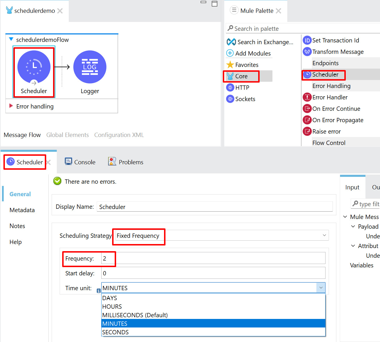
Figure 8.4 – Scheduler properties
In Figure 8.4, we have configured our Scheduler to run every 2 minutes. If we need to change Time unit to DAYS, HOURS, MILLISECONDS, or SECONDS as per the requirements, then we can configure the Scheduler timings accordingly.
Note
We can achieve similar Fixed Frequency scheduling using the Cron scheduling strategy. Cron is a job in the UNIX operating system that follows a specific syntax to mention the scheduling frequency/timing. It is used for scheduling specific tasks at a fixed time or specific intervals. If you are familiar with the Cron expression, then you can use the Cron scheduling strategy. For more information about Cron, refer to this link: https://en.wikipedia.org/wiki/Cron.
- Next, select the Core module and drag and drop Logger from Mule Palette to the canvas.
- In the Logger properties, specify Message as Scheduler invoked, as shown in the following figure:

Figure 8.5 – Logger properties
In Figure 8.5, we have configured the Logger properties Message setting with Scheduler invoked for our demo in order to understand whether a Scheduler flow has been triggered or not at a specific time. In a real use case, instead of Logger, we will have other components or connectors to process the files or messages from one system to another at a specific time.
- Click Save, or press Ctrl + S, to save the Mule application.
- Go to the canvas, right-click, and select Run project SchedulerDemo.
- Now embedded Mule runtime starts inside Anypoint Studio and deploys the application. Once the application is deployed successfully, then we will be able to see the logs with the status as DEPLOYED.
- Watch the console for a few minutes. You will be able to see the Scheduler getting invoked every 2 minutes.

Figure 8.6 – Console
In Figure 8.6, the Console view is showing that the Scheduler was running every 2 minutes and printing the message Scheduler invoked, which we specified in the Logger properties.
With this, we have learned how to trigger or call a Mule application using the Scheduler component. Scheduler is used mainly when we have a requirement to handle or process the message in an asynchronous manner. For example, if we need to sync or send the sales order information from a CRM to an ERP system, then we can use the Scheduler component to run at a specific time to pick up the records from Salesforce and send them to the other system.
Let’s move on to learning how to generate flows automatically using API specification and route them through APIkit Router.
Generating a flow using APIkit Router
APIkit Router generates the whole flow based on the API specification file. It receives the incoming request, validates it, and routes the incoming request to the flow.
If you have already created an API specification (or an API design) and you want to start developing the actual implementation, you can import your API specification into Anypoint Studio and APIkit will create the basic flows and error handling for your API based on the specification. By doing this, we need not create all the code from scratch.
It is always best practice to create the API specification first in API Designer. Once it is created, we can start building the Mule application with that API specification. This is called an API design-first approach. There is also the code-first approach, which mandates having an API specification but does not emphasize starting with the API design (specification) first. In the API design-first approach, the developer can consume the API to develop in parallel, which shortens the time to market. Hence, the API design-first approach is recommended over the code-first approach.
Now, let’s create a Mule application using the API design specification.
Creating a Mule application using an API specification
Let’s learn how to create a Mule application using an API specification to understand how APIkit Router will autogenerate the flows and route the request to different flows:
- Go to Anypoint Studio. Click the Create a Mule Project option from Package Explorer to create a new Mule application.
- Provide the project name as APIkitRouterDemo, select the Import RAML from local file option, and browse for the RAML file that we created in Chapter 2, Designing Your API. Leave the remaining settings as is and click the Finish button. This RAML file is also available on GitHub in the Chapter2 folder, which is linked in the Technical requirements section.

Figure 8.7 – Creating a Mule project using API Specification (RAML)
In Figure 8.7, musicbox-sys-api.raml is the RAML file that we will be using to create the Mule application.
Now, it will automatically generate all the required flows in our Mule application. It consists of flows such as main and console and also flows for each HTTP method, such as get and post.
When our application runs, the main flow is the one that actually receives the request.

Figure 8.8 – main flow
In Figure 8.8, we can see that the main flow has HTTP Listener with the path as /api/* to receive the request and APIkit Router to validate and route the request to the get/post flow. If any validations fail, it will throw an exception, which will be handled by the error handler that is mentioned in this main flow. Error handling can handle the following error types:
- BAD_REQUEST
- NOT_FOUND
- METHOD_NOT_ALLOWED
- NOT_ACCEPTABLE
- UNSUPPORTED_MEDIA_TYPE
- NOT_IMPLEMENTED
Now, let’s see the different components that are autogenerated as a part of the API console flow.

Figure 8.9 – Console flow
In Figure 8.9, the console flow has HTTP Listener with the path set to /console/* to receive the request and APIkit Console to validate and route the request. A console flow is mainly used for API documentation. This helps to test the API locally using interactive documentation.

Figure 8.10 – API console documentation
Once we’ve run the Mule application, we can open the API documentation using the URL http://localhost:8081/console/ from the browser, as shown in Figure 8.10. Using this API console, we can explore the API documentation and test the API using different methods such as get and post.
Now, let us see the components that are autogenerated as a part of the get and post HTTP methods.

Figure 8.11 – Autogenerated HTTP methods
Our API specification had only two methods, get and post. Hence, it has generated two flows. Each HTTP method (get and post) has one flow with the Transform Message component, which sends the song sample response as defined in the API specification, which is highlighted in Figure 8.11. Now, we have seen different autogenerated flows for main, console, get, and post.
This way, we can easily create a Mule application using RAML, which in turn autogenerates all the flows and error handling. Now, our job is only to make minor changes to accommodate our requirements. For example, in our implementation of a get or post flow, if we need to fetch or create, respectively, the song data from the backend application, we just replace Transform Message with the required connectors.
With this, we have created a Mule application using an API specification (RAML) file. Now, let us see how to run and test the application.
Running and testing a Mule application
In this section, let us run and test the Mule application using Postman. While testing, we’ll use different methods, such as get, put, and post, to check different scenarios:
- Go to the canvas and right-click Run project apikitrouterdemo.
Once the application has deployed successfully, we will be able to see the logs with the status as DEPLOYED in the Anypoint Studio Console view.
- Go to Postman, set the method to GET, provide the URL as localhost:8081/api/songs, and click Send.

Figure 8.12 – Sending a request from a Postman application with the get method
In Figure 8.12, we can see that we have sent the request from Postman to our Mule application with the get method. On receiving the request, the Mule application processes the request and sends the response back.
Our APIkitRouterDemo Mule application receives the request in the main flow HTTP Listener and sends the request to APIkit Router, where it is validated. If the validation is successful, then it identifies the HTTP method and routes it to the appropriate flow. In our case, we have sent the request using the GET method from Postman, hence it invokes the get flow to process the incoming request.
A high-level sequence of processing will look as follows:
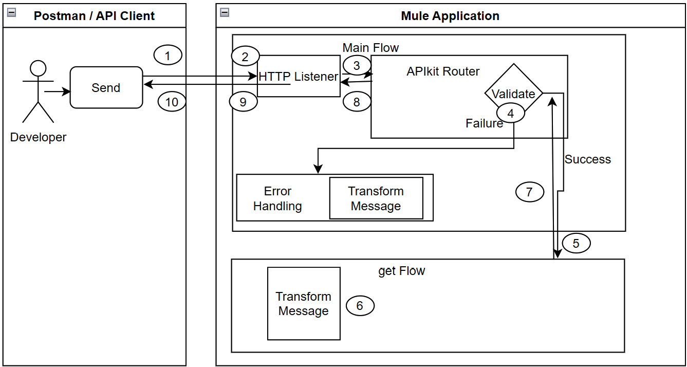
Figure 8.13 – High-level processing sequence
- Now, let’s try to send the request from the Postman application using the put method. We will get a response as "message": "Method not allowed". We are receiving this response because our main flow doesn’t have a flow for the put method. This invokes error handling and matches with the corresponding error type METHOD_NOT_ALLOWED and sends the response.
- Try to send the request from the Postman application with the post method to the URL localhost:8081/api/songs/1.
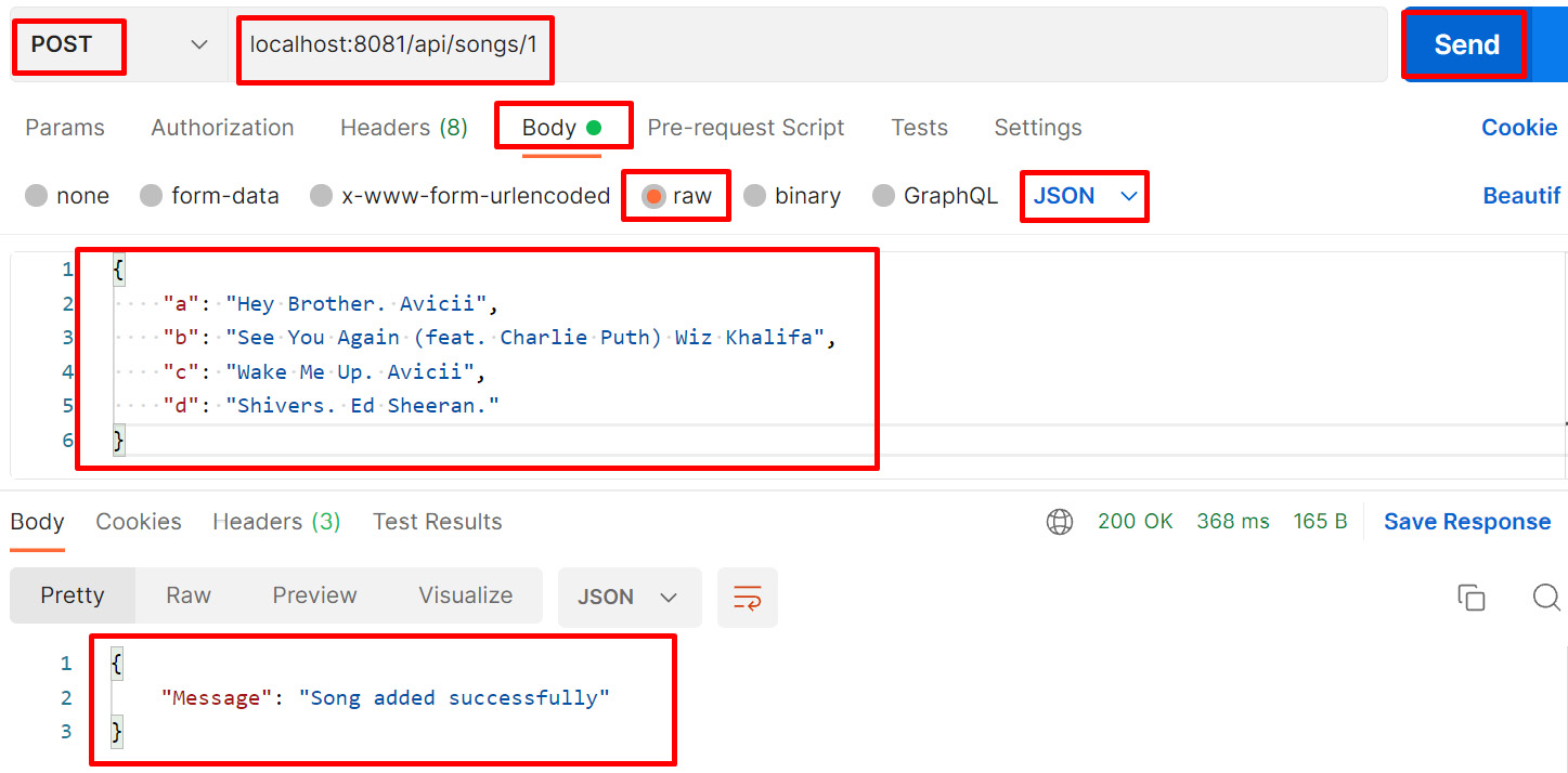
Figure 8.14 – Sending a request from the Postman application with the post method
In Figure 8.14, we have sent the song data in the request body from Postman to our Mule application with the post method, the Mule application receives the request, and after processing it, it sends the response back.
While sending the request, we are passing a value of 1 in the URL, which is nothing more than the URL parameter value. The post flow receives the request that we passed in the body of the request and sends the response back. In our example, the response, "Message": "Song added successfully", comes from the Transform Message setting of the post flow.
But in the actual implementation, Mule application extracts the value that comes in the URL parameters along with the request payload and sends it to the backend applications. Finally, the backend application generates the success or failure response message. In this test, we passed a value of 1, which is a songsid. When the application receives the request payload with 1, the Mule application creates the song data in the backend application with a songsid with the value of 1 and sends the success response back. If there is any failure while creating the song data in the backend system, it sends a failure response back. For a successful response, we will send 200 OK. Here, 200 is the HTTP status code and OK is the HTTP status description.
For a failure response, based on the error type, the Mule application will send a different HTTP status code and status description. For example, if we pass the put method, which is not there in our flow, then it will send a status code of 405 Method Not Allowed.
Now, we have understood how to build and run a Mule application using APIkit Router.
Let’s move on to explore how to use Object Store Connector in a Mule application.
Exploring Object Store Connector
Object Store Connector is a Mule component that allows you to store a simple key-value pair. A key-value pair is a combination of two simple values where one is the key and the other is a value. The key is the unique identifier of the values stored.
The following are the operations of Object Store Connector. We can use these operations in order to manage our key-value pair:
- Store: To store the value using the key
- Retrieve: To retrieve the value stored using a specific key
- Retrieve All: To retrieve all the key-value pairs from the object store
- Retrieve All Keys: Lists all the keys that are available in the object store
- Contains: To check whether any value against the key is available in the object store or not
- Remove: To remove the value for a specific key from the object store
- Clear: To remove all the keys from the object store. In turn, all values will also be removed
Different types of Object Store
There are three types of Object Store:
- Object Store v2: This is only supported in CloudHub and is a cloud service. Use the Object Store v2 option while deploying the application in CloudHub. Otherwise, based on the runtime version, the runtime manager will choose either Object Store v2 or Object Store v1. Here, key-value pairs are stored externally to the Mule application. The time to live (TTL) is 30 days and after that, the key-value pair will get removed from the Object Store. The maximum size for a key value is 10 MB. The standard version supports 10 transactions per second (TPS) and the premium version supports 100 TPS as the API request limit. Object store v2 is not recommended for multi-worker configurations, because Store operation will overwrite the key values in case of concurrent requests.
- Object Store v1: This is only supported in CloudHub and is currently deprecated. The end of life (EOL) is not confirmed. It is encouraged to use the latest version, Object Store v2. TTL is not configurable. The maximum size for a key value is 1 MB. There is no API request limit. Mule 4 does not support Object Store v1.
- Object Store: This is used in an on-premises environment and is a part of the Mule runtime. We can store the keys and values in memory for faster performance or disk (persistent) for reliability. There is no limit to the key-value size.
Let’s apply some of these operations in a Mule application.
Creating a Mule application with Object Store Connector
Let’s learn how to create a Mule application with Object Store Connector to understand how the object store uses the key to store and retrieve the data. We will be creating two different flows in this project. One is StoreFlow, which is used to store the key in the object store, and another one is RetrieveFlow, which is used to retrieve the key from the object store:
- Go to Anypoint Studio. Choose the Create a Mule Project option in Package Explorer to create a new Mule application.
- Provide the project name as ObjectStoreDemo.
- Next, select HTTP in Mule Palette and then select Listener.
- Drag and drop Listener onto the canvas.
- Select Listener from the canvas. In the Listener properties, add the connection configuration by pressing the Add symbol, as shown in the following figure:

Figure 8.15 – Mule properties for HTTP Listener
- Leave the host and port (8081) values at the default values and click the OK button on the connector configuration screen.
- Once done, set the Path value as /store.
- Click Add Module from Mule Palette and drag and drop ObjectStore, as shown in the following figure:

Figure 8.16 – Adding the object store to Project | Mule Palette
- Click ObjectStore from Mule Palette and drag and drop Store onto the canvas. Configure the key as lastProcessedSongID with the value as 5 and the object store name as SongsObjectStore by clicking the plus symbol, as shown in Figure 8.17:
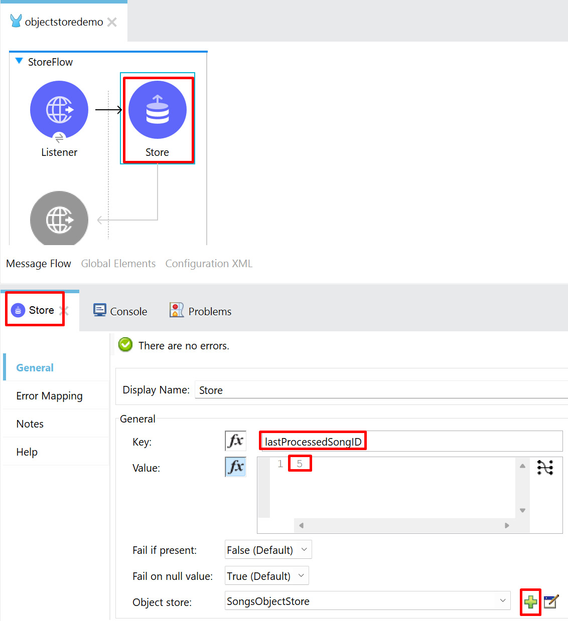
Figure 8.17 – Store configuration
- Change the name of the flow to StoreFlow and save the Mule application. Now we have created a flow that stores the value in the object store. Let’s create another flow in the same project to retrieve the value from the object store based on the key.
- In the same project, create another flow with HTTP Listener, with the path set to /retrieve and the flow name set to RetrieveFlow.
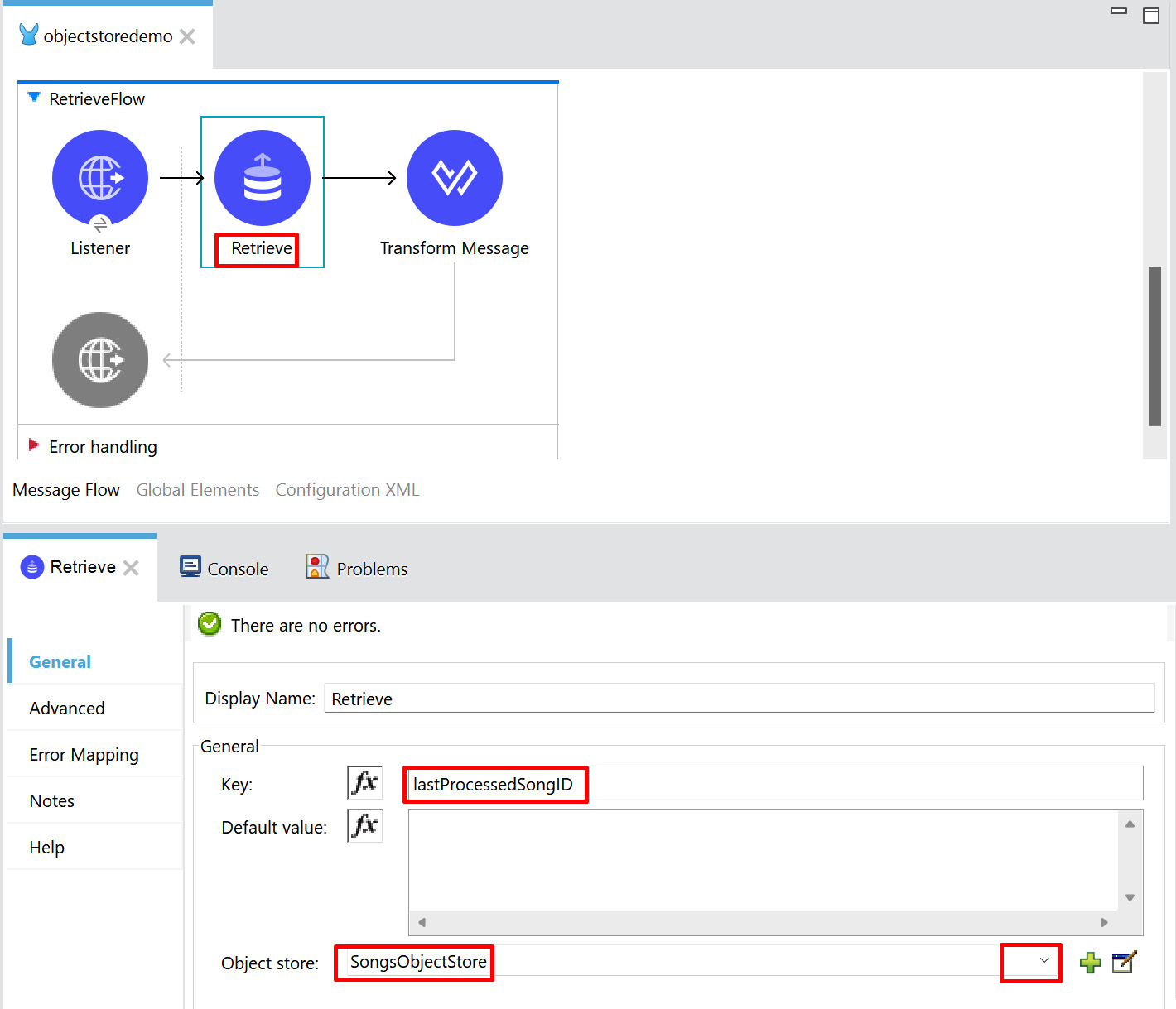
Figure 8.18 – Retrieve flow
As in Figure 8.18, provide the key as lastProcessedSongID in the Retrieve operation and set the object store name to SongsObjectStore, which we have already specified in StoreFlow.
- Add TransformMessage after the Retrieve operation and add the DataWeave coding to the Output tab, as shown in the following figure:
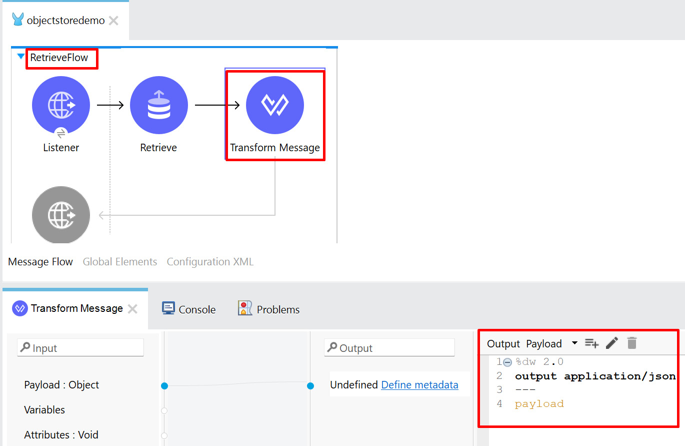
Figure 8.19 – Transform Message
- Click Save, or press Ctrl + S, to save the Mule application.
- Run the Mule application from the canvas. Once the application has deployed successfully, we will be able to see the logs with the status as DEPLOYED.
- Open the Postman application. In the URL box, enter http://localhost:8081/store, then click Send.
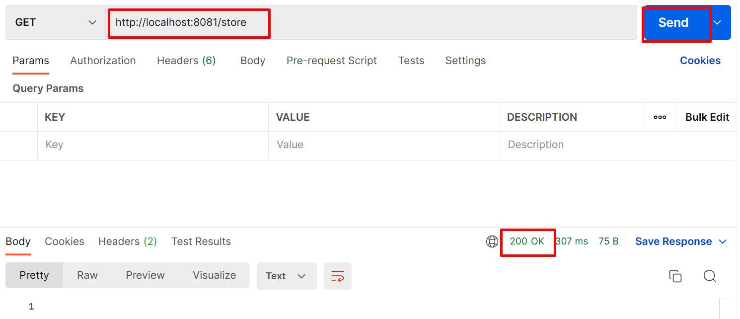
Figure 8.20 – Sending the request to the Store flow
In the preceding figure, we can see that the response received is 200 OK, which means that our application has received the request and stored the key (lastProcessedSongID with the value 5) in the object store successfully.
Let us try to retrieve the stored value from object store:
- In the URL box, enter http://localhost:8081/retrieve, then click Send.

Figure 8.21 – Sending the request to the Retrieve flow
In Figure 8.21, we can see the response received is 5 with the HTTP status code and description as 200 OK. This means we are able to successfully retrieve the lastProcessedSongID value stored in the object store.
For example, if we are synchronizing the song data from one system to another, then we need to store the last processed record value (lastProcessedSongID) in the object store. So, the next time the interface runs, it fetches the record from the system, which is yet to be processed to another system, with the help of the last processed record value (lastProcessedSongID).
With this, we have understood how to create an object store and store and retrieve values to and from the object store.
Summary
In this chapter, we had a look at various types of configuration files in the Mule application.
We created a Mule application using Scheduler, after which we tried to run it, and finally, we tested it using an external Postman application.
We also learned about creating a Mule application using the API specification. We saw how APIkit Router helps create flows automatically and route the flows into different HTTP methods. We tested methods such as get, put, and post to see the success and failure scenarios.
Our next topic was how to use Object Store Connector in a Mule application.
On completing this chapter, you have an elaborate knowledge of how to build a Mule application using Scheduler, API Specification, and Object Store Connector and should feel confident enough to develop your own Mule application.
In the next chapter, Chapter 9, Deploying Your Application, we’ll explore further different ways to deploy our application.
Questions
Take a moment to answer the following questions to serve as a recap of what you just learned in this chapter:
- Which .xml file will have project dependencies information in a Mule application?
- What are the different types of scheduling strategies?
- What is APIkit Router?
- What is Object Store Connector?
Answers
- pom.xml
- There are two types of scheduling strategies:
- Fixed Frequency
- Cron
- APIkit Router is a tool for creating a Mule application. It autogenerates the flow using a RAML file. It receives the incoming request, validates the URL, query parameters, and URI parameters based on the API specification, and also routes the incoming request to the Mule flow.
- Object Store Connector is a Mule component that allows you to store a simple key-value pair.