Chapter 11. Configuring Single Sign-On
This chapter covers the following topics:
- Active Directory Single Sign-On Overview
- Supported Devices for AD SSO
- Basic AD SSO Configuration Steps
- Configuring Single Sign-On for Windows AD
- Configuring Single Sign-On for VPN
- Configuring Single Sign-On for Cisco Wireless LAN Controller
This chapter covers how to configure Single Sign-On (SSO) for the following deployments. Step-by-step screen shots and explanations of each deployment are provided. For details of the benefits that SSO provides, review the single sign-on material in Chapter 5, "Advanced Cisco NAC Appliance Design Topics."
- Active Directory Single Sign-On (AD SSO)
- Cisco Virtual Private Network (VPN) SSO
- Cisco Wireless SSO
Active Directory Single Sign-On Overview
Prior to NAC Appliance 4.0, a typical Windows user running NAC Agent would have to manually log in via the NAC Agent prompt to gain access to the network. The NAC Agent login is an additional login step to the Ctrl-Alt-Delete login process that all Windows users go through when booting up their machine. Many users complained that the extra login was a hassle and inconvenient.
Starting with 4.0, that extra login step for Windows users logging in to the domain has been removed. Windows users simply enter their login name and password as they normally do when booting into their Windows desktop via Ctrl-Alt-Delete, and NAC Agent takes care of the rest. NAC Agent takes the user's login credentials and automatically passes that info to NAC Appliance for authentication. After being successfully authenticated and posture assessed, the user is mapped to an assigned role and granted the appropriate network access.
Supported Devices for AD SSO
Single Sign-On in a LAN is supported only in a Windows environment with Active Directory (AD) deployed. AD SSO requires NAC Agent to be installed for SSO to work. NAC Agent leverages the cached Windows login credentials and Kerberos ticket from the host PC and uses them for authentication without additional user login. Table 11-1 shows OS support for Active Directory SSO.
Table 11-1. Operating System Support for Active Directory SSO

Basic AD SSO Configuration Steps
Before configuring AD SSO, you should have a good understanding of the AD domain structure. The following are several items that you will need to prepare:
- Windows 2000 or Windows 2003 Server installation CD. This CD is required to install the support tools needed for the ktpass command. The ktpass command is required to be run on the AD server or domain controller that the NAS is logging in.
- The fully qualified domain name (FQDN) of the AD server that the NAS logs in to.
- NAC Appliance Server (NAS) and NAC Appliance Manager (NAM) must be able to resolve the FQDN of the AD server.
A summary of the configuration steps is as follows:
Step 1. In NAM, add the NAS to be managed.
Step 2. In NAM, add the AD server as AD SSO Auth Server.
Step 3. Configure traffic policies and ports in unauthenticated role for AD authentication.
Step 4. In NAS, configure the AD server settings. This includes the NAS user account and FQDN settings of the AD server.
Step 5. In the AD server, add the NAS user account that NAS will use to log in to the AD server.
Step 6. In the AD server, run the ktpass command to configure encryption parameters to support Linux OS of the NAS.
Step 7. In the NAS, enable the Agent-Based Windows Single-Sign-On service.
Step 8. (Optional) Enable Group Policy Object (GPO) updates.
Step 9. (Optional) Add a Lightweight Directory Access Protocol (LDAP) lookup server for AD SSO if mapping users to multiple roles is required after authentication.
Step 10. Make sure that the current time in the NAM, NAS, and AD server are all in sync.
Configuring Single Sign-On for Windows AD
This section provides a step-by-step configuration example of how to configure AD SSO. The example chosen here is a Layer 2 Out-Of-Band (OOB) Real-IP deployment. This model is used because most high-speed LAN deployments will be OOB for performance reasons. In addition, Real-IP has the capability to provide a /30 or 30-bit mask address that will quarantine an infected end host before accessing the network. Note that most enterprise networks already have a DHCP infrastructure in place. Therefore, it is strictly optional for customers if they would like to use the 30-bit mask functionality in NAS. Figure 11-1 shows the topology of this Layer 2 OOB Real-IP example.
Figure 11-1. Layer 2 OOB Real-IP NAS Deployment

NAM Configuration
From the command-line interface (CLI) of NAM, use the service perfigo config command to set up the NAM IP info. The CCA software used is version 4.1.0. Example 11-1 shows the configuration setup script.
Example 11-1. Configuring NAM via CLI
Fedora Core release 4 (Stentz)
Kernel 2.6.11-perfigo on an i686
cam1 login: root
Password:
[root@cam1 ~]# service perfigo config
Welcome to the Cisco Clean Access Manager quick configuration utility.
Note that you need to be root to execute this utility.
The utility will now ask you a series of configuration questions.
Please answer them carefully.
Cisco Clean Access Manager, (C) 2006 Cisco Systems, Inc.
Configuring the network interface:
Please enter the IP address for the interface eth0 [192.168.137.3]: 192.168.10.100
You entered 192.168.10.100. Is this correct? (y/n)? [y]
Please enter the netmask for the interface eth0 [255.255.255.0]:
You entered 255.255.255.0. Is this correct? (y/n)? [y]
Please enter the IP address for the default gateway [192.168.137.1]: 192.168.10.1
You entered 192.168.10.1. Is this correct? (y/n)? [y]
Please enter the hostname [cam1]: NAM1
You entered NAM1. Is this correct? (y/n)? [y]
Please enter the IP address for the name server: [192.168.100.100]: 192.168.10.110
You entered 192.168.10.110. Is this correct? (y/n)? [y]
Would you like to change shared secret? (y/n)? [y]
Please remember to configure the Clean Access Server with the same string. Please
enter the shared secret between Clean Access Server
You entered: cisco123
Is this correct? (y/n)? [y]
>>> Configuring date and time:
The timezone is currently set to:America/Los_Angeles
Would you like to change this setting? (y/n)? [y] n
Current date and time hh:mm:ss mm/dd/yy [23:20:08 12/17/06]: 15:20:00 12/17/06
You entered 15:20:00 12/17/06. Is this correct? (y/n)? [y]
Sun Dec 17 15:20:00 PST 2006
You must generate a valid SSL certificate in order to use the Clean Access Manager's
secure web console.
Please answer the following questions correctly.
Information for a new SSL certificate:
Enter fully qualified domain name or IP: NAM1.selab.net
Enter organization unit name: cisco
Enter organization name: cisco
Enter city name: san jose
Enter state code: ca
Enter 2 letter country code: us
You entered the following:
Domain: NAM1.selab.net
Organization unit: cisco
Organization name: cisco
City name: san jose
State code: ca
Country code: us
Is this correct? (y/n)? [y]
Generating SSL Certificate...
CA signing: /root/.tomcat.csr -> /root/.tomcat.crt:
CA verifying: /root/.tomcat.crt <-> CA cert
/root/.tomcat.crt: OK
Done
For security reasons, it is highly recommended that you change the default passwords
for the root user.
User: root
Changing password for user root.
New UNIX password:
Retype new UNIX password:
passwd: all authentication tokens updated successfully.
Changes require a RESTART of Clean Access Manager.
Configuration is complete.
[root@cam1 ~]# service perfigo reboot
NAS Configuration
From the CLI of the NAS appliance, use the service perfigo config command to set up the NAS IP info. Example 11-2 shows how to configure NAS via CLI.
Example 11-2. Configuring NAS via Configuration and Setup Script
[root@cas1 ~]# service perfigo config
Welcome to the Cisco Clean Access Server quick configuration utility.
Note that you need to be root to execute this utility.
The utility will now ask you a series of configuration questions.
Please answer them carefully.
Cisco Clean Access Server, (C) 2006 Cisco Systems, Inc.
Configuring the network interfaces:
Please enter the IP address for the interface eth0 [10.1.110.2]: 192.168.10.10
You entered 192.168.10.10. Is this correct? (y/n)? [y]
Please enter the netmask for the interface eth0 [255.255.255.0]:
You entered 255.255.255.0. Is this correct? (y/n)? [y]
Please enter the IP address for the default gateway [10.1.110.1]: 192.168.10.1
You entered 192.168.10.1. Is this correct? (y/n)? [y]
[Vlan Id Passthrough] for packets from eth0 to eth1 is disabled.
Would you like to enable it? (y/n)? [n]
[Management Vlan Tagging] for egress packets of eth0 is disabled.
Would you like to enable it? (y/n)? [n]
Please enter the IP address for the untrusted interface eth1 [10.1.111.2]:
192.168.199.1
You entered 192.168.99.1. Is this correct? (y/n)? [y]
Please enter the netmask for the interface eth1 [255.255.255.0]:
You entered 255.255.255.0. Is this correct? (y/n)? [y]
Please enter the IP address for the default gateway [10.1.111.1]: 192.168.199.2
You entered 192.168.10.1. Is this correct? (y/n)? [y]
[Vlan Id Passthrough] for packets from eth1 to eth0 is disabled.
Would you like to enable it? (y/n)? [n]
[Management Vlan Tagging] for egress packets of eth1 is disabled.
Would you like to enable it? (y/n)? [n]
Please enter the hostname [cas1]: NAS1
You entered NAS1. Is this correct? (y/n)? [y]
Please enter the IP address for the name server: [10.1.112.105]: 192.168.10.110
You entered 192.168.10.110. Is this correct? (y/n)? [y]
Would you like to change shared secret? (y/n)? [y]
Please enter the shared secret: cisco123
You entered: cisco123
Is this correct? (y/n)? [y]
>>> Configuring date and time:
The timezone is currently set to:America/Los_Angeles
Would you like to change this setting? (y/n)? [y] n
Current date and time hh:mm:ss mm/dd/yy [15:39:15 12/17/06]:
You entered 15:39:15 12/17/06. Is this correct? (y/n)? [y]
Sun Dec 17 15:39:15 PST 2006
You must generate a valid SSL certificate in order to use the Clean Access Server's
secure web console.
Please answer the following questions correctly.
Information for a new SSL certificate:
Enter fully qualified domain name or IP: NAS1.selab.net
Enter organization unit name: cisco
Enter organization name: cisco
Enter city name: san jose
Enter state code: ca
Enter 2 letter country code: us
You entered the following:
Domain: NAS1.selab.net
Organization unit: cisco
Organization name: cisco
City name: san jose
State code: ca
Country code: us
Is this correct? (y/n)? [y]
Generating SSL Certificate...
CA signing: /root/.tomcat.csr -> /root/.tomcat.crt:
CA verifying: /root/.tomcat.crt <-> CA cert
/root/.tomcat.crt: OK
Done
For security reasons, it is highly recommended that you change the default password
for the root user.
User: root
Changing password for user root.
New UNIX password:
Retype new UNIX password:
passwd: all authentication tokens updated successfully.
Would you like to change the default password for the web console admin user
password? (y/n)? [y]
Please enter an appropriately secure password for the web console admin user.
New password for web console admin:
Confirm new password for web console admin:
Web console admin password changed successfully.
Configuration is complete.
[root@cas1 ~]# service perfigo reboot
Layer 3 3550 Core Switch Configuration
Example 11-3 shows the working configuration in the Layer 3 3550 core switch using Cisco IOS Software Release 12.2(25)SEE2.
Example 11-3. 3550 Core Switch Configuration
hostname 3550_core
!
vtp domain cisco
vtp mode transparent
!
vlan 10
name ManagementVlan10
!
vlan 15
name Internet
!
vlan 20
name AccessVlan20
!
vlan 99
name AuthenticationVlan99
!
vlan 1004
bridge 1
!
vlan 1005
bridge 1
!
!
interface FastEthernet0/1
description Active Director/DNS
switchport access vlan 10
switchport mode access
spanning-tree portfast
!
interface FastEthernet0/2
description Link to Internet
switchport access vlan 15
switchport mode access
spanning-tree portfast
!
interface FastEthernet0/3
description NAM
switchport access vlan 10
switchport mode access
spanning-tree portfast
!
interface FastEthernet0/4
description NAS Eth0 Trusted
switchport access vlan 10
switchport mode access
spanning-tree portfast
!
interface FastEthernet0/5
description NAS Eth1 Untrusted
switchport trunk encapsulation dot1q
switchport trunk native vlan 10
switchport trunk allowed vlan 20,99,199
switchport mode trunk
!
!
!<Omit... to save paper>
!
!
interface FastEthernet0/24
description Link to edge 3500 XL L2 switch
switchport trunk encapsulation dot1q
switchport trunk native vlan 10
switchport trunk allowed vlan 10,20,99
switchport mode trunk
!
interface Vlan10
description User Vlan 10
ip address 192.168.10.1 255.255.255.0
!
interface Vlan15
description Internet link
ip address 10.2.2.55 255.255.255.0
!
interface Vlan20
description User Access Vlan 20
ip address 192.168.20.1 255.255.255.0
shutdown
!
interface Vlan199
description Link to NAS Eth1 Real-IP
ip address 192.168.199.2 255.255.255.0
!
ip classless
ip route 0.0.0.0 0.0.0.0 10.2.2.1
ip route 192.168.99.0 255.255.255.0 192.168.10.10
ip http server
ip http secure-server
!
!
snmp-server group cam_user v3 auth notify *tv.00000001.00000000.00000020.000000000F
snmp-server group cam_group v3 auth write v1default notify v1default
snmp-server group 3550_group v3 auth write v1default
snmp-server community cisco123 RO
snmp-server location SELab
snmp-server contact Jerry Lin
snmp-server enable traps snmp linkdown
snmp-server enable traps mac-notification
!
line con 0
exec-timeout 0 0
length 0
line vty 0 4
exec-timeout 0 0
password cisco
login
line vty 5 15
password cisco
login
!
mac-address-table notification interval 0
mac-address-table notification
end
3500XL Edge Layer 2 Switch Configuration
Example 11-4 shows the 3500XL edge Layer 2 switch configuration using software version c3500XL-c3h2s-mz.120-5.3.WC.1.bin. Note that the 3500XL switches have been designated End-Of-Life by Cisco. Although the 3500XL switch is still supported by NAM and NAS, Cisco best practices recommend that customers deploy active Cisco LAN switches that are not on the End-Of-Sale or End-Of-Life list. The current switches support many popular enhanced security features, such as SNMP Version 3. For the simplicity of this example, the 3500XL is used with SNMP Version 1.
Example 11-4. 3500XL Edge Layer 2 Switch Output
interface FastEthernet0/1
switchport access vlan 99
spanning-tree portfast
!
interface FastEthernet0/2
switchport access vlan 99
spanning-tree portfast
!
interface FastEthernet0/3
switchport access vlan 99
spanning-tree portfast
!
!
interface FastEthernet0/23
switchport access vlan 99
spanning-tree portfast
!
interface FastEthernet0/24
description Trunk to core 3550 L3 switch
switchport trunk encapsulation dot1q
switchport trunk native vlan 10
switchport trunk allowed vlan 1,10,20,99,1002-1005
switchport mode trunk
!
interface VLAN1
no ip address
no ip directed-broadcast
no ip route-cache
shutdown
!
interface VLAN10
ip address 192.168.10.35 255.255.255.0
no ip directed-broadcast
no ip route-cache
!
ip default-gateway 192.168.10.1
logging trap debugging
snmp-server engineID local 000000090200000628F8F8C0
snmp-server community cisco123 RW
snmp-server enable traps snmp authentication linkdown linkup coldstart
snmp-server host 192.168.10.100 trap cisco123 snmp
!
line con 0
exec-timeout 0 0
length 0
transport input none
stopbits 1
line vty 0 4
password cisco123
login
!
end
Active Directory or Domain Controller Configuration
The AD server in this deployment is a Windows 2003 Server Enterprise Edition with Service Pack 1. The AD server's FQDN is win2003-ad-ca.selab.net. The computer name of the AD server is "win2003-ad-ca". The domain name is "selab.net". Figure 11-2 shows the FQDN of the AD server win2003-ad-ca.selab.net.
Figure 11-2. FQDN of the AD Server

This AD server is also the DNS server for this sample deployment.
Beginning Overall Setup
In any NAC deployment, a single NAM (primary) or a pair of NAMs (active and standby) can manage up to 40 NAS appliances. This means that nearly all the NAS configurations can be performed within the NAM GUI. But first, NAS has to be added to NAM. The following steps detail how to add NAS to the NAM:
Step 1. Go to Device Management > CCA Servers > New Server.
Step 2. Enter the server IP of the NAS: 192.168.10.10.
Step 3. Enter the server location: SE Lab.
Step 4. Select the server type Out-Of-Band Real-IP Gateway.
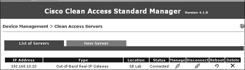
Step 5. Click Add Clean Access Server. Figure 11-3 shows NAS as status Connected after being added successfully.
Figure 11-3 displays the Clean Access Server (NAS) added to the NAM.
Figure 11-3. OOB Real-IP NAS Added
Adding an AD Server as an AD SSO Auth Server
The following steps show how to add an AD server in NAS as an AD SSO authentication server:
Step 1. In NAM, go to User Management > Auth Servers > New.
Step 2. Select the authentication type Active Directory SSO.
Step 3. Enter the provider name ADSSO.
Step 4. Leave the default role as Unauthenticated Role. This is the default user assigned role unless it is overridden by the LDAP Lookup Server field.
Step 5. For now, leave the LDAP lookup server as NONE. This step will be created later.
Step 6. In the Description field, enter ADSSO.
Step 7. Click Add Server.
Figure 11-4 shows the addition of an AD SSO authentication server.
Figure 11-4. Adding an AD SSO Authentication Server

Configuring Traffic Policies and Ports in the Unauthenticated Role for AD Authentication
By default, NAS permits only DNS and DHCP traffic in the Unauthenticated role. For AD users to authenticate via Kerberos to the AD domain, ports must be opened on NAS to allow the authentication process to pass through in the Unauthenticated role. This will also allow GPO and scripts to run after the user authentication. The required TCP and User Datagram Protocol (UDP) ports are listed next.
Required TCP ports:
- TCP 88 (Kerberos)
- TCP 135 (remote-procedure call [RPC])
- TCP 389 (LDAP) or TCP 535 (LDAP with Secure Sockets Layer [SSL])
- TCP 1025 (RPC), nonstandard
- TCP 1026 (RPC), nonstandard
Alternative UDP ports:
If you do not know whether the AD server is using Kerberos, open the following UDP ports as well:
- UDP 88 (Kerberos)
- UDP 389 (LDAP) or UDP 636 (LDAP with SSL)
- Internet Control Message Protocol (ICMP)
To configure the ports, do the following:
Step 1. Go to User Management > User Roles > List of Roles > Policies(icon)_[Unauthenticated role].
Step 2. Make sure that the screen shows Unauthenticated Role, Untrusted->Trusted. Click Add Policy.
Step 3. Make sure of the following settings:
— Priority = 1
— Action = Allow
— State = Enabled
— Category = IP
— Protocol = TCP,6
— Untrusted (IP/Mask:Port) = */*,*
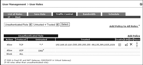
Step 4. Change Trusted(IP/Mask:Port) to AD server: 192.168.10.110/255.255.255.255, 88,135,389,1025,1026.
Step 5. Enter an optional description: User AD authentication policy.
Step 6. Click Add Policy.
Step 7. Repeat the preceding steps for the alternative UDP ports and ICMP.
Figure 11-5 shows the user AD authentication policy in Unauthenticated role. Only the TCP traffic policy is shown. The UDP traffic policy should be added by an administrator.
Figure 11-5. TCP Traffic Policy Added for AD Authentication During Unauthenticated Role
Configuring AD SSO Settings in NAS
To configure AD SSO Settings in NAS, do the following:
Step 1. Go to Device Management > CCA Servers > List of Servers > Manage(icon)_192.168.10.10.
Step 2. Select Authentication > Windows Auth > Active Directory SSO.
Step 3. Account for CAS: For smaller networks where a single Active Directory server is deployed, click the Single Active Directory Server option. For large enterprise networks where multiple AD servers are deployed, click the Domain (All Active Directory Servers) option. For this simple example, the single AD server option is selected. The multiple Active Directory server option is available only in NAC Appliance software 4.1.1 and higher.
Step 4. Active Directory Server (FQDN): win2003-ad-ca.selab.net. This is the full computer name of the AD server.
Step 5. Active Directory Domain: SELAB.NET. The domain name here must be in all capital letters.
Step 6. Account Name for CAS: ccasso. This is the user account name for NAS in AD.
Step 7. Account Password for CAS: Cisco123. Password policy is subject to Active Directory password policy. The Plain password cisco123 would not work. AD requires at least one capital letter.
Step 8. Active Directory SSO Auth Server: ADSSO.
Step 9. Click Update. Do not check the Enable Agent-Based Windows Single Sign-On with Active Directory (Kerberos) check box yet. The NAS user account has not yet been created in AD.
Figure 11-6 shows how to configure Active Directory SSO settings in NAS.
Figure 11-6. Single AD Server Configuration

Configuring the AD Server and Running the ktpass Command
The following is how to prepare and configure the AD server for AD SSO:
Step 1. Create the NAS user account in AD.
Step 2. Install the support tools from the Windows 2003 Server CD.
Step 3. Run the ktpass.exe command.
Creating the NAS User Account in AD
Use the following steps to create the NAS user account in the AD server:
Step 1. In the AD server, go to Start > Administrative Tools > Active Directory Users and Computers.
Step 2. Go to the Users folder under the AD domain. In this example, the AD domain is selab.net.
Step 3. Right-click Users > New > User.
Step 4. Enter the user account name for NAS. In this example, the NAS user account is "ccasso." Click Next after entering the ccasso user credential. Figure 11-7 shows the creation of the NAS user account in AD.
Figure 11-7. Creating the NAS User Account in AD

Step 5. At the password screen, enter a password acceptable by AD. The sample password used is Cisco123. Also, click on Password Never Expires. (This is common practice for service accounts only.) If you choose to allow AD to expire the NAS user password, you must go back into the NAS and change the AD SSO account password when AD expires the account. Click Next when complete.
Step 6. Review the NAS user logon name and password expiration period. If okay, click Finish. You should see the ccasso account successfully created in AD.
Installing the Support Tools from the Windows 2003 Server CD
To install the support tools from the Windows 2003 Server CD, do the following:
Step 1. Within your Windows 2003 Server CD, go to the D:SUPPORTTOOLS directory. You should see the SUPTOOLS.MSI installer package. Double-click it to start the installation process.
Step 2. Follow the typical Windows installation process and click Finish when complete.
Step 3. When complete, go to the C:Program FilesSupport Tools directory, where you should see many new files. ktpass.exe (~80kB) should be there.
Caution
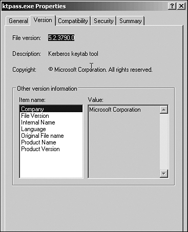
At the time of this writing, the current verified version of ktpass.exe that works with NAC AD SSO is file version 5.2.3790.0. Other versions of ktpass failed to work with NAC AD SSO. Figure 11-8 shows the compatible ktpass.exe file version for AD SSO.
Figure 11-8. Supported Version of the ktpass.exe File
Running the ktpass.exe Command
The ktpass.exe file is required because NAC Appliance uses a Linux OS. Linux uses Data Encryption Standard (DES) encryption, whereas Microsoft Active Directory uses RC4 encryption for Kerberos. For NAC appliance to communicate to MS AD in Kerberos, both have to agree on a common encryption format. Running the ktpass.exe command on the AD domain controller changes the NAS user account to use DES-only encryption.
In addition, every domain controller that the NAS communicates with must run the ktpass.exe command. This applies to multiple controllers used by multiple NAS server under a single domain. The NAS user account will be replicated to other multiple controllers, but the map user functionality will have to be modified on each domain controller. Therefore, the ktpass.exe command has to be run on each domain controller defined on NAS. Keep the following in mind:
- ktpass.exe must be run in a DOS window. Open a DOS window. Change the directory to the Support Tools directory using cdprogram filessupport tools.
- The ktpass.exe command line is rather lengthy. Please execute with caution and accuracy because typos are very common.
The ktpass.exe command syntax is as follows:
ktpass.exe -princ NASusername/Full_AD_DomainName@AD_DOMAIN -mapuser NASusername
  -pass NASpassword -out c:NASusername.keytab -ptype KRB5_NT_PRINCIPAL +DesOnly
In this case:
- NASusername (this is the NAS user account name): ccasso
- NASpassword: Cisco123
- Full_AD_DomainName (case sensitive): win2003-ad-ca.selab.net
- AD_DOMAIN (must be all capitals): SELAB.NET
Example 11-5 shows a sample ktpass.exe execution.
Example 11-5. Sample ktpass.exe Command Run
C:Program FilesSupport Tools>ktpass.exe -princ ccasso/win2003-ad-
[email protected] -mapuser ccasso -pass Cisco123 -out c:ccasso.keytab -ptype
KRB5_NT_PRINCIPAL +DesOnly
Targeting domain controller: win2003-ad-ca.selab.net
Successfully mapped ccasso/win2003-ad-ca.selab.net to ccasso.
Key created.
Output keytab to c:ccasso.keytab:
Keytab version: 0x502
keysize 67 ccasso/[email protected] ptype 1 (KRB5_NT_PRINCIPAL)
vno 3 etype 0x3 (DES-CBC-MD5) keylength 8 (0x91cec19e40f4e3dc)
Account ccasso has been set for DES-only encryption.
Note
It is highly recommended that the ktpass.exe output be saved for support and troubleshooting purposes with Cisco Technical Assistance Center when needed.
Enabling Agent-Based Windows AD SSO
Now that the AD server has been configured, you need to enable the Agent-based Windows SSO service in the NAS by doing the following:
Step 1. Go to Device Management > CCA Servers > Manage icon > NAS_IP > Authentication > Windows Auth > Active Directory SSO.
Step 2. Click the Enable Agent-Based Windows Single Sign-On with Active Directory (Kerberos) check box.
Step 3. Click Update. If there have not been any typos or misconfigurations along the way, the AD SSO service on the NAS should start within 3–5 seconds. The Enable Agent-Based Windows Single Sign-On with Active Directory (Kerberos) check box should remain checked. If there is a misconfiguration somewhere, you will see an error message in red print above the check box.
Step 4. To verify that the AD SSO service has indeed started, go to Device Management > CCA Servers > Manage icon [NAS_IP] > Status. The Active Directory SSO module status should say Started. See Figure 11-9 to verify the AD SSO service starting.
Figure 11-9. Verify That the AD SSO Service Has Started

Enabling GPO Updates
Starting with NAC software 4.1.0, NAC Agent (4.1.0) can retrigger a GPO update after an AD user has signed in to the network. This is helpful in ensuring that all AD domain users inherit the appropriate user policies as defined by the AD administrator. For example, the administrator can create a policy that prevents the users from changing their desktop wallpaper. With the 4.1.0 release, NAC Agent executes the gpupdate command to retrigger the Group Policy update after login and prevent users from changing their desktop wallpaper.
To trigger the GPO update, do the following:
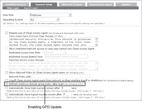
Step 1. Go to Device Management > Clean Access > General Setup > Agent Login.
Step 2. Select the appropriate user role, such as employee/faculty or student, to which this GPO update should apply. Outside guests or temporary visitors most likely would not participate in Active Directory.
Step 3. Select All for the operating system.
Step 4. Check the box Refresh Windows Domain Group Policy After Login (for Windows Only). Click Update. See Figure 11-10 on enabling GPO Update.
Figure 11-10. Enabling Windows Domain Group Policy Update After User Login
(Optional) Adding LDAP Lookup Server to Map Users to Multiple Roles
If you plan to map AD SSO users to multiple user roles, you will have to configure a secondary LDAP Lookup server in the NAM. For example:
- User student1 should be mapped to a Students user role with limited network access.
- User employee1 should be mapped to an Employee role with full network access.
- User visitor1 should be mapped to a Visitors role with only http/https network access.
NAM will map the user logging in based on the AD attributes and the mapping rules created. However, if only basic AD SSO without multiple role assignment is required, it is not necessary to configure an LDAP lookup server. For this test network, three roles are created to map users to specific roles after successful authentication.
LDAP Browser (Not Required but Very Helpful)
Before configuring an LDAP lookup server in NAM, having a good understanding of Active Directory and LDAP tree structure is helpful. To assist with this learning, an LDAP directory browser is highly recommended. For this exercise, a free LDAP browser from Softerra (http://www.softerra.com/) is used to help walk through the LDAP tree and correctly identify user attributes. Softerra is probably not the only free LDAP browser available on the Internet. You can use any other tool you choose to achieve the same goal. For now, the following describes how to use the Softerra LDAP browser to get started:
Step 1. Install Softerra LDAP Browser (Version 2.6) on your laptop or desktop machine.
Step 2. Launch the LDAP browser and click File > New Profile. The profile name used in this lab is SElab. Click Next.
Step 3. At the Host Information screen, enter the AD server IP (in this case, Host: 192.168.10.110). Leave all other fields at the default value. See Figure 11-11 on entering AD/LDAP server IP address. Click Next.
Figure 11-11. Using an LDAP Browser to Access AD Domain Structure

Step 4. Click Yes when prompted "Base DN is not specified. Continue anyway?"
Step 5. At the credentials screen, enter the User DN (ccasso) and Password (Cisco123). This is the NAS user account created earlier in AD. Click Next.
Step 6. At the LDAP Settings window, delete the default parameter in the Filter field. Leave everything else at the default. Click Finish.
Step 7. When prompted with the Password Dialog window, enter Cisco123. Click OK.
Step 8. Allow the free LDAP Browser to walk through the LDAP tree over a few minutes. The LDAP structure slowly expands in the browser. Expand the SElab domain controller and click CN=Users > CN=ccasso. See Figure 11-12 for the user ccasso LDAP structure.
Figure 11-12. LDAP Structure Info for User ccasso

Step 9. See the base context for user ccasso in the Value column: CN=ccasso, CN=Users, DC=selab, DC=net.
Configuring LDAP Lookup Server in NAM
After the LDAP structure info has been acquired for user ccasso, you can enter the user into the LDAP lookup server in NAM. The configured info is how NAS will access AD for user account lookups:
Step 1. Go to User Management > Auth Servers > Lookup Servers > New. Enter the information that follows.
— Server URL: ldap://192.168.10.110:389
— Search(Admin)Full DN: CN=ccasso, CN=Users, DC=selab, DC=net. This info is taken from the LDAP browser for NAS user account ccasso.
— Search Base Context: CN=Users, DC=SELAB, DC=NET. This is the base context (root of the LDAP tree) to begin a search for the users. Make sure all DC values are in capital letters.
— Referral: Manage (Ignore). Sets whether referral entries are managed or returned as handles (Handle(Follow)).
— DerefAlias: Always (default).
— Description (optional): LDAP Lookup for ADSSO
— Provider Name: LDAP Lookup
— Server Version: Auto
— Search(Admin) Password: Cisco123
— Search Filter: sAMAccountName=$user$
— DerefLink: OFF
— Security Type: None
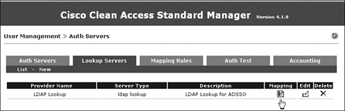
Step 2. Click Add Server. See Figure 11-13 for a screen shot of adding an LDAP Lookup server.
Figure 11-13. LDAP Lookup Server Configuration for AD SSO

Step 3. Now that the LDAP lookup server has been added, the AD SSO auth server configured earlier (see Figure 11-4) needs to reference the LDAP lookup server for the role mapping. Click User Management > Auth Servers > Edit[ADSSO].
Step 4. Select LDAP Lookup Server: LDAP Lookup. This LDAP Lookup server will map AD SSO users to their appropriate roles when the mapping rules are matched. This role mapping also overrides the default role of Unauthenticated Role.
Step 5. Click Update Server.
User Attributes in Active Directory
Active Directory tree structure can be multilevel and quite complex. Therefore, it is important that the NAC Appliance administrator work with the AD server administrators to coordinate the user-role-to-AD-attribute mapping effort. The scope of this book is not to discuss how to correctly configure and deploy AD in an enterprise environment. Therefore, the test lab used in this exercise is simplified to demonstrate the technique of how to map AD user attributes to NAC mapping rules.
Earlier, three user roles (Employee, Students, Visitors) were discussed. These roles are maintained in NAM itself and are referred to by all the NAS Appliances after authenticating users to determine the correct role to assign. To do this, simply go to NAM > User Management > User Roles > New. Enter one role name at a time: Employee, Students, or Visitors. Leave all other fields at their default values. Click Add when done with one role. The GUI is fairly intuitive. What these roles mean in the Layer 2 switch world is that multiple VLANs must be created for this out-of-band test network.
In this lab setup, VLAN 99 is the untrusted authentication VLAN. Any users coming online will be initially placed in VLAN 99. Access VLAN 20 is a trusted VLAN. Any users passing authentication and posture assessment will be switched to VLAN 20 from 99. Ideally, multiple access VLANs would be created for multiple user roles. However, to keep this lab network simple, only VLAN 20 is demonstrated. All Employees, Students, and Visitors are mapped to access VLAN 20.
In the AD world, three different groups are most likely to be created. Full-time employees and faculty members would fall into the Employee group. Students would fall into the Students group, and visitors and contractors belong in the Visitors group. Here's how to create the simplified AD groups and users in AD:
Step 1. In the AD server, go to the Active Directory Users and Computers window. Select the Users folder under the Selab.net domain.
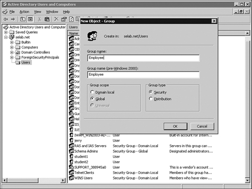
Step 2. Right-click Users > New > Group. Enter the group name of Employee. Select Global for Group Scope and Security for Group type. Click OK. Figure 11-14 shows creating the Employee group in AD.
Figure 11-14. Creating the Employee Group Object in AD
Step 3. The Employee global security group should now be created. Repeat the same process to create groups for Students and Visitors. Figure 11-15 shows the three new groups created in AD.
Figure 11-15. Creating Multiple Group Objects in AD

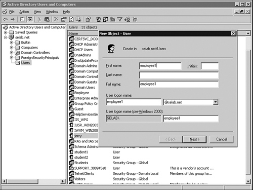
Step 4. Now create users for each group. Right-click Users > New > user. Enter employee1 name. First name=employee1, User logon name=employee1. Leave other fields blank or at the default value. Click Next. Figure 11-16 shows adding user employee1.
Figure 11-16. Creating User employee1 in AD
Step 5. Enter a user password and confirm it. This example's password is Cisco123. Password Never Expires is checked for the purposes of this simplified test lab network. Click Next.
Step 6. Click Finish after you verify your entries. Repeat the process by adding the users student1 and visitor1.
Step 7. Next, each user should be assigned to its respective group: Employee1 > Employee group, student1 > Students, and so on. Right-click user employee1, select the Member Of tab, click Add, enter the object name employee, and click the Check Names button. Figure 11-17 shows assigning user employee1 to group Employee.
Figure 11-17. Associating a User with the Employee Group

Step 8. The Employee group should be found. Click OK. User employee1 should now be a member of the Employee group, so verify its Employee group membership. Click Apply and OK when verified.
Step 9. Repeat the same process for the users student1 and visitor1.
Step 10. Using the LDAP browser, verify that employee1, student1, and visitor1 are members of their related groups. Notice that Users > employee1 is memberOf CN=Employee, CN=Users, DC=selab, DC=net. The same applies to student1 and visitor1. Figure 11-18 shows employee1 is a member of the CN=Employee group.
Figure 11-18. User employee1 Is a Member of the Employee Group

Step 11. Go back to NAM. Go to User Management > Auth Servers > Lookup Server > Mapping (icon)[LDAP Lookup]. Click the Mapping icon. Figure 11-19 shows the creation of mapping rules for the LDAP lookup server.
Figure 11-19. Create Mapping Rules for the LDAP Lookup Server
Step 12. Click Add Mapping Rule in the upper-right side of the screen.
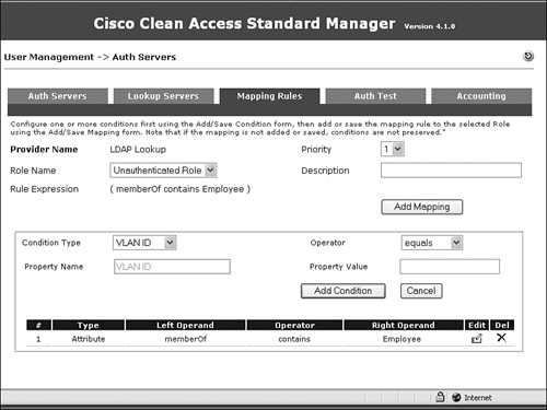
Step 13. In the bottom half of the screen, select Condition Type=Attribute, Attribute Name=memberOf, Operator=contains, Attribute Value=Employee, and click the Add Condition button. Figure 11-20 shows the addition of the memberOf attribute for the Employee role.
Figure 11-20. Defining the memberOf Attribute for the Employee Role
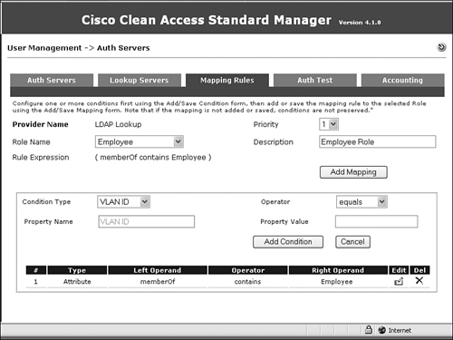
Step 14. Near the top half of the screen, select Role Name=Employee and Description=Employee Role. Click the Add Mapping button. Figure 11-21 shows the mapping of attributes to the Employee role.
Figure 11-21. Associating the memberOf Attribute with the Employee Role
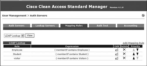
Step 15. Repeat the same process for Students and Visitors roles. Figure 11-22 shows the output after all three roles are mapped.
Figure 11-22. LDAP Lookup Rules for Three Defined Roles
The AD SSO setup process is complete. However, there are other NAC setup tasks to perform before testing AD SSO.
Step 16. Go to Device Management > Clean Access > General Setup > Agent Login. Select Employee from the User Role drop-down menu. Select All from the Operating System drop-down menu.
Step 17. Check the Require Use of Clean Access Agent (for Windows & Macintosh OSX Only) box. Click Update. Figure 11-23 shows the NAC Agent general setup.
Figure 11-23. Checking This Box Requires All Users in the Employee Role and Using Windows and Mac OS X Machines to Have NAC Agent Installed

Step 18. Because this is an OOB deployment, the edge 3500XL switch must be added to NAM. Details of how to configure OOB are discussed in Chapter 10, "Configuring Out-of-Band." But here are some instructions. Go to Switch Management > Profiles > Group > New. Enter Group Name=3500XL and Description=3500XL switches. Click Add.
Step 19. The OOB switch profile must be created next. Go to Switch Management > Profiles > Group > New. Enter Profile Name=control20 and Description=User Vlan 20. Check the Manage This Port box.
Step 20. Under VLAN Settings, set Auth VLAN: VLAN ID:99, Default Access VLAN: VLAN ID:20, and Access VLAN: Default Access VLAN.
Step 21. Check the Bounce the Port After VLAN Is Changed box.
Step 22. Check the Remove Out-of-Band Online Users When SNMP Linkdown Trap Is Received box.
Step 23. Click Add.
Step 24. Go to Profiles > Switch > New. Enter Profile Name=3500XL and select switch model=Cisco Catalyst 3500XL series, SNMP port=161, and SNMP read/write v1 string=cisco123. Click Add.
Step 25. At the Profile > Group > List screen, find the 3500XL group name and click the magnifying glass icon under the Switches column.
Step 26. Click Switches > Search. The switch profile should be 3500XL. Enter the IP range of 192.168.10.35 – 192.168.10.35. Click Search.
Step 27. After clicking Search, select Switch Group=3500XL and Default Port Profile=control20. Check the box for the discovered 3500XL switch, 192.168.10.35. Click Commit.
Step 28. Go to Profiles > SNMP Receiver > SNMP Trap. Enter SNMPv1 settings and Community String=cisco123. Leave the other fields at their default value because they are not used. Click Update.
Enabling DHCP in NAS
For this sample deployment, NAS is the DHCP server providing a /30 or 30-bit subnet mask for each user in the authentication VLAN 99. The advantage of a 30-bit mask is that an infected host cannot reach any other hosts while in the auth VLAN. The infected host is essentially quarantined. NAS performs a posture assessment of that host and, if certified, the host is switched to the access VLAN 20 with another IP address assigned to access VLAN 20.
In a real-world deployment where a corporate DHCP server is used instead of using NAS as the DHCP server, the access VLAN 20 would not be managed by NAS. Only VLAN 99 would be managed by NAS. But for simplicity in this example, NAS is configured as the corporate DHCP server for VLAN 99 and 20. Therefore, NAS manages both the access VLAN 20 and authentication VLAN 99. The following is an example of setting up a DHCP server in NAS:
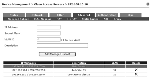
Step 1. For this L2 deployment, authentication VLAN 99 and access VLAN 20 must be managed by NAS. Go to Device Management > CCA Servers > Manage (icon) [192.168.10.10] > Advanced > Managed Subnet. Enter the following:
— IP address=192.168.199.1
— Subnet Mask=255.255.255.0
— VLAN ID=99
— Description=Auth Vlan 99
Click Add Managed Subnet.
Step 2. Repeat the same process for access VLAN 20.
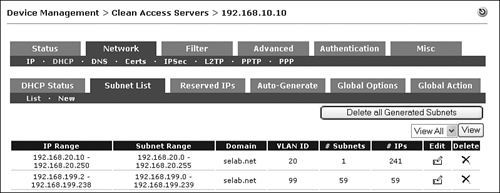
Step 3. When complete, you will see Figure 11-24, which shows auth VLAN 99 and access VLAN 20 added to the managed subnets. As a reminder, access VLAN 20 is managed by NAS only because NAS is acting as the corporate DHCP server.
Figure 11-24. VLANs Managed by the NAS
Step 4. Go to Device Management > CCA Servers > Manage (icon) [192.168.10.10] > Network > DHCP. Choose DHCP Server and click the Select DHCP Type button. When you select the DHCP server from None to DHCP Server, NAS will prompt you to reboot.
Step 5. Select the Auto-Generate tab and enter the following:
— Enter Starting IP = 192.168.199.0
— Number of Subnets to Generate = 60
— General Subnet Size = /30 –1 IP per Subnet
— Default Lease Time (Seconds) = 7200
— Max Lease Time (Seconds) = 7200
— DNS Suffix = selab.net
— DNS Servers = 192.168.10.110
— WINS Servers = <blank>
Check the Restrict This Subnet to VLAN ID box. Enter VLAN ID=99.
Step 6. Click Generate Subnet List. You should see a list of 60 /30 subnets. Click Commit Subnet.
Step 7. Now the user access VLAN 20 DHCP scope must also be created. Go to Network > DHCP > Subnet List > New. Figure 11-25 shows adding in DHCP scope for access VLAN 20. Click Update when complete.
Figure 11-25. Adding in a DHCP Scope for Access VLAN 20

Step 8. When both DHCP scopes are complete, Figure 11-26 shows what you should see.
Figure 11-26. DHCP Scopes Generated for VLANs 20 and 99
Enabling User Login Pages in NAM
Go to Administration > User Pages > Login Page. Click Add. Select Operating System=WINDOWS_ALL.
NAC Agent Download and Login
To take advantage of AD SSO, the end-user machine Windows XP or Windows 2000 must first download NAC Agent. There are multiple ways to download NAC Agent:
- Manually download NAC Agent from the NAM GUI and install NAC Agent on each end-user machine—not an easily scalable solution.
- Use a software distribution application such as Altiris, PatchLink, and so on, to push NAC Agent down to each user machine.
- Force the end users to download NAC agent when they try to browse the Internet. NAC appliance will intercept the HTTP request and present the user with a login prompt and then the NAC Agent download screen.
The following is a demonstration of the last option from the preceding list:
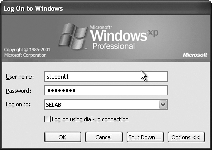
Step 1. The user first logs in to a machine in the SELAB.net domain. Figure 11-27 shows user student1 logging in to the SELAB domain.
Figure 11-27. Main Windows XP Login for the User student1
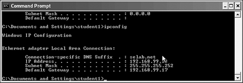
Step 2. After signing on, verify that the IP address of the Windows XP machine is in VLAN 99 with a 192.168.99.x/30 subnet. Figure 11-28 shows that the XP machine is in VLAN 99 with 192.168.99.18 255.255.255.252 IP and subnet mask.
Figure 11-28. Verifying Initial User IP Address in Authentication VLAN 99
Step 3. Launch a browser and try to connect to the NAM. Mostly likely, a security alert will pop up regarding a new security certificate. This is normal because the client has never trusted NAC Appliance's digital certificate. Click Yes. As an option, you can click View Certificate and install the certificate so that you won't be prompted to accept the NAC certificate again in the future.
Step 4. Next, the user's HTTP request is intercepted and redirected to the NAC authentication page. Another security alert pops up regarding untrusted digital certificates. Click Yes to proceed. Figure 11-29 shows the NAC redirect page during initial user login.
Figure 11-29. Initial Security Alert for an Untrusted Digital Certificate

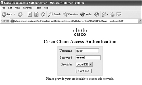
Step 5. Next is the Cisco Clean Access Authentication Login page. Because this lab network was not configured with an LDAP authentication server (for web login), the Guest user account in the NAM local database can be used to log in. A guest user account was already created in the local database. Figure 11-30 shows the NAC web login page.
Figure 11-30. NAC Web Login Page
Step 6. After login, the user is prompted to download NAC Agent. Figure 11-31 shows the NAC 4.1.0 Agent download page via web login.
Figure 11-31. Web User Being Directed to Download NAC Agent 4.1.0

Step 7. Open or save CCAAgent_Setup.exe from NAS1.selab.net and install. Be sure that you have administrative privileges to install NAC Agent. Simply follow the typical Windows installation process and click Finish when the installation is complete.
Step 8. After the installation, NAC Agent should automatically discover NAS Appliance on the network and initiate the Single Sign-On process. You might be prompted with a security alert because of the unknown certificate from NAC Appliance. Click Yes and proceed. Figure 11-32 shows the AD SSO process.
Figure 11-32. Performing Windows AD SSO Automatic Login

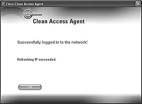
Step 9. Finally, after authentication (and posture assessment, if it is configured), NAM switches the client PC from the auth VLAN 99 to the access VLAN 20. NAC Agent issues a "Refreshing IP . . ." message and the client acquires a new IP address, 192.168.20.x /24, within access VLAN 20. Figure 11-33 shows a successful OOB logon with the new IP in access VLAN 20.
Figure 11-33. Successful User Login to Access VLAN 20; the User Also Acquires a New IP Address for Access VLAN 20
Configuring Single Sign-On for VPN
Single Sign-On for NAC + Cisco VPN provides a similar user login experience to AD SSO. However, in IPsec or SSL VPN access, the user is typically prompted with a VPN username and password login. After the users enter their username and password, NAC Appliance can assign the appropriate user role based on RADIUS accounting information received from the RADIUS authentication server used by the VPN concentrator. Figure 11-34 shows the NAC Appliance and Cisco VPN test network diagram.
Figure 11-34. Deploying NAC over VPN

The VPN SSO setup in this test network consists of the following components:
- NAC Manager (4.1.x).
- NAC Server (4.1.x).
- Cisco Access Control Server (ACS) 3.3.
- Cisco Adaptive Security Appliance (ASA) 5510 (7.2.2) with SSLVPN Tunnel Client (sslclient-win-1.1.3.173.pkg). Adaptive Security Device Manager (ASDM) 5.2.2 is used to configure the ASA 5510.
- Remote client PC has NAC Agent installed.
Only In-Band mode supports VPN SSO at the time of this writing.
The following is a high level summary for configuring SSO over Cisco VPN:
Step 1. Configure the RADIUS server (ACS Server). Add users and authentication, authorization, and accounting (AAA) clients (ASA, NAM, and NAS).
Step 2. Set up SSLVPN in the ASA-5510. Add ACS to ASA for RADIUS authentication. Add NAS as the RADIUS accounting server.
Step 3. Configure NAS to support VPN SSO.
The scope of this book is not to show details of how to configure or design Cisco SSLVPN services. Therefore, only the main VPN configuration portions that interact with NAC Appliance are demonstrated. For basic VPN setup reference, see the following Cisco.com URL for a VPN setup example: http://www.cisco.com/en/US/products/ps6120/products_configuration_example09186a008071c428.shtml.
ACS Setup
In this test network, Cisco ACS is used as the back-end RADIUS authentication server. VPN users and RADIUS clients must be added. Figure 11-35 shows the added RADIUS clients.
Figure 11-35. Added AAA Clients

ASA-5510 VPN Setup
Here's a summary of enabling SSLVPN in the ASA appliance. Again, not all the SSLVPN setup steps are shown. ASDM is used to configure ASA.
Step 1. Enable WebVPN for the Outside interface. Figure 11-36 shows enabling WebVPN.
Figure 11-36. Enabling WebVPN Services on the Outside Interface Using the ASDM GUI

Step 2. Load and enable the SSLVPN tunnel client. Figure 11-37 shows the loading of the SSLVPN tunnel client.
Figure 11-37. SSLVPN Client Image Must Be Loaded into the ASA Appliance

Step 3. Go to the IP address assignment section. Select Use Internal Address Pools and create your IP address pools. Figure 11-38 shows the creation of IP address pools.
Figure 11-38. Creating IP Address Pools for SSLVPN Users

Step 4. Next, go to the AAA server section and create the RADIUS authentication server group. Figure 11-39 shows the creation of the AAA server group.
Figure 11-39. Creating the AAA Server Group

Step 5. Now a RADIUS server (192.168.10.111) must be added to the AAA server group. Figure 11-40 shows the addition of a RADIUS server.
Figure 11-40. Defining the RADIUS Server Under the AAA Server Group

Step 6. Next, a RADIUS accounting server group must be created so that the ASA VPN concentrator will send the RADIUS accounting start packet to pass the user role assignment info and to perform Single Sign-On. Figure 11-41 shows adding a RADIUS accounting group called NAS_Accounting.
Figure 11-41. Adding a RADIUS Accounting Group

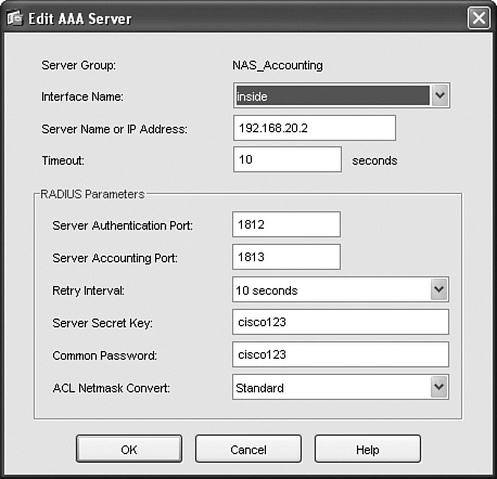
Step 7. The RADIUS accounting server, which is NAS 192.168.20.2, must be added to the NAS_Accounting RADIUS accounting group. Figure 11-42 shows the addition of NAS as the RADIUS accounting server.
Figure 11-42. Adding NAS as the RADIUS Accounting Server
Step 8. The WebVPN tunnel policy must select the NAS_Accounting group. Figure 11-43 shows the selection of the NAS_Accounting group.
Figure 11-43. Associating the NAS_Accounting Group to the WebVPN Tunnel Policy

Configuring NAS to Support VPN SSO
After the user authenticates to the concentrator, it sends a RADIUS accounting start packet to NAS. NAS then completes the SSO process with NAC Agent and adds that host to the certified device list. The same process applies when a user terminates a VPN tunnel. The concentrator sends a RADIUS accounting stop packet to NAS, and NAS removes that user from the certified device list.
The final step is to enable VPN SSO capabilities within NAS. Follow these steps to do so:
Step 1. Go to the NAS-VPN appliance from the NAM GUI and select the Authentication > VPN Auth > General page. Set Single Sign-On, Auto Logout. Set RADIUS Accounting port: 1813 and click Update. Figure 11-44 shows the configuration of the SSO and RADIUS accounting port.
Figure 11-44. Configuring VPN SSO in NAS

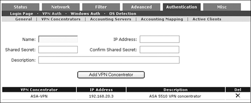
Step 2. Go to the Authentication > VPN Auth > VPN Concentrator page. Add the ASA-5510 VPN concentrator. See Figure 11-45.
Figure 11-45. Adding the ASA Appliance as a VPN Concentrator
Step 3. Go to the Authentication > VPN Auth > Accounting Servers page. Add the ACS server as the RADIUS accounting server. See Figure 11-46.
Figure 11-46. Adding the ACS Server as the RADIUS Accounting Server

Step 4. Next, the ASA VPN concentrator and the RADIUS accounting server must be mapped together. Figure 11-47 shows mapping the VPN concentrator to the RADIUS accounting server.
Figure 11-47. Mapping the ASA VPN Concentrator to the ACS Accounting Server

Step 5. Go back to the User Management > Auth Servers page. Now the Cisco VPN SSO authentication server must be added. Assign Default Role=Employee for now to permit full network access for all authenticated VPN users. Add Description: Remote VPN support.
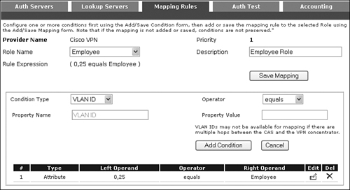
Step 6. With the Cisco VPN SSO server created, mapping rules must be created to assign the appropriate user roles based on RADIUS accounting the vendor-specific attribute value 25. Go to Auth Servers > List > Cisco VPN > Mapping (icon).
Step 7. To create the mapping rule for the Employee user role, vendor attribute 25 [Class] must be added. The property value or right operand value Employee is the keyword used to match against the vendor-specific attribute 25 [Class] value sent inside the RADIUS accounting packet from the accounting server. Figure 11-48 shows creating the Employee mapping rule. This value is mapped to the Employee role.
Figure 11-48. Vendor Attribute 25 [Class] Mapping for the Employee Role
Step 8. You can repeat the previous step to create another mapping rule for the Student role. After you have successfully done so, a summary of the Cisco VPN mapping rules will appear.
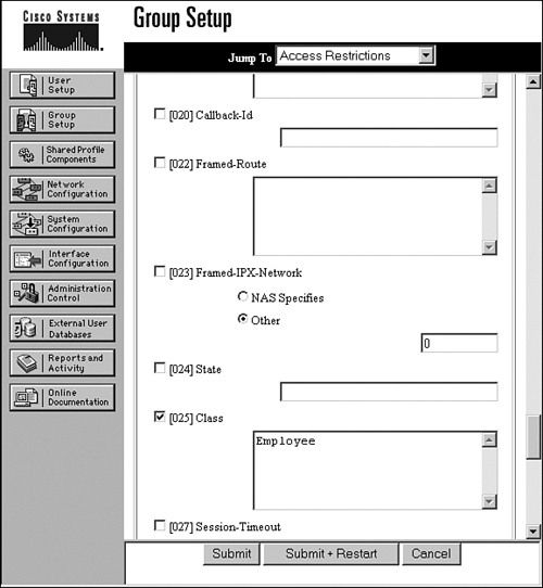
Step 9. The final step is to return to the ACS RADIUS server and assign the correct vendor-specific attribute 25 [Class] values for each user. In this test network, user1 is part of Group 1 Employee. In ACS, go to Group Setup > Group:Employee > Edit Settings, and make sure that the [025] Class box is checked and the keyword value is Employee. Figure 11-49 shows the RADIUS vendor-specific attribute [025] Class value setting.
Figure 11-49. RADIUS Vendor-Specific Attribute Setting of Attribute [25] Class in ACS
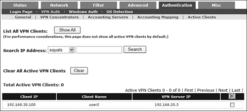
Step 10. Finally, if all configurations are accurate and valid, you should see that when VPN clients connect to the VPN concentrator, they will automatically sign in to NAC without an additional username and password login. You can view the active VPN clients within NAS by going to Device Management > CCA Servers > Manage[192.168.20.2] > Authentication > VPN Auth > Active Clients. See Figure 11-50.
Figure 11-50. View the Active NAC-VPN Clients
Configuring Single Sign-On for Cisco Wireless LAN Controller
Configuring Single Sign-On for Cisco Wireless LAN Controller (WLC, from Airespace acquisition) is similar to configuring SSO for Cisco VPN SSO. From the NAS and NAM perspectives, WLC functions as if it were a VPN concentrator. In fact, adding WLC through the NAM GUI is done by adding a VPN concentrator logically. WLC communicates with NAM through RADIUS accounting, and NAM assigns user roles based on default rules or mapping rules you create. The WLC SSO setup in this test network consists of the following components:
- NAC Manager (4.1.x).
- NAC Server (4.1.x).
- Cisco Access Control Server (ACS) 3.3.
- Cisco Wireless LAN Controller (4.0.179.11).
- Cisco AP 1200 access point with Lightweight Access Point Protocol (LWAPP) support.
- Wireless client PC has NAC Agent installed for WLC SSO.
Like VPN SSO, WLC SSO is supported only in In-Band mode. See Figure 11-51 for the WLC SSO network diagram.
Figure 11-51. Wireless LAN Controller SSO Network
The following is a high-level summary for configuring single sign-on for Cisco Wireless LAN Controller:
Step 1. Configure the RADIUS server (ACS Server). Add users and AAA clients (ASA, NAM, and NAS).
Step 2. Set up WLC wireless settings. Add ACS to WLC for RADIUS authentication. Add NAS as RADIUS accounting server.
Step 3. Configure NAS to support VPN SSO for WLC. WLC is added to NAS as a floating device if the WLC is deployed as a router hop.
ACS Server Setup
The configuration of the ACS server is nearly identical to the VPN SSO setup. Users are added in the same way. Simply add WLC as a RADIUS client.
WLC Setup
The goal of this chapter is not to teach you how to configure and deploy Wireless LAN Controller. Therefore, only relevant screenshots are shown in the following steps:
Step 1. Figure 11-52 shows the basic IP address and software version of WLC.
Figure 11-52. WLC Software and IP Summary

Step 2. Under the Controller > General menu, LWAPP transport mode must be enabled for Layer 3. In addition, enter a mobility domain name. A sample domain name used is irvlab. Figure 11-53 shows enabling LWAPP Transport Mode in Layer 3.
Figure 11-53. WLC General Controller Setting for Layer 3

Step 3. Go to Controller > Interfaces and add in the user traffic VLAN information. Figure 11-54 shows the added interfaces.
Figure 11-54. WLC Interface Summary

Step 4. Next, the RADIUS authentication server must be added. Go to Security > AAA > RADIUS Authentication. Click New to add the ACS server. Figure 11-55 shows the added RADIUS authentication server.
Figure 11-55. Adding a RADIUS Authentication Server in WLC

Step 5. The RADIUS accounting server must be added next. Click the Radius Accounting link and then click New. Figure 11-56 shows the added RADIUS accounting server.
Figure 11-56. Adding a RADIUS Accounting Server in WLC

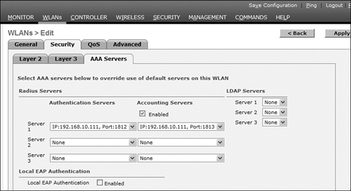
Step 6. Go to the WLANs menu and find the irvlab WLAN SSID. Click irvlab SSID and make sure the WLAN status is Enabled. In addition, make sure that the correct RADIUS authentication and accounting servers are selected on the AAA Servers tab. See Figure 11-57 for a summary.
Figure 11-57. AAA Servers Used in WLC
NAM/NAS Setup
With the ACS and WLC components configured, the next step is to add WLC into NAS. Adding WLC into NAS is similar to adding a VPN concentrator, as shown in the following steps:
Step 1. Go to the NAM GUI and manage the NAS used for the WLC. NAS in this setup is a Real-IP gateway. Make sure to check the Enable L3 Support check box.
Step 2. Go to the Advanced > Managed Subnet page and add the user VLAN 99. This step is similar to the managed subnet setup in the VPN SSO section.
Step 3. Go to the Authentication > VPN Auth > General page and enable the Single Sign-On boxes along with RADIUS Accounting port 1813.
Step 4. Go to the Authentication > VPN Auth > VPN Concentrators page. Add the WLC unit as a VPN concentrator.
Step 5. Go to the Authentication > VPN Auth > Accounting Servers page. Add the NAS server (not the ACS server) as the RADIUS accounting server.
Step 6. Go to the Authentication > VPN Auth > Accounting Mapping page. The WLC entry must be mapped to the ACS accounting server. Click Add Entry.
Step 7. WLC must be added as an authentication server. Go to the User Management > Auth Servers > New page. Add WLC as a Cisco VPN SSO authentication type. The default role can be Allow All. Allow All is a created role that has full network access. This role assigns all authenticated wireless users full network access.
Note
For this simple test network, we assigned all authenticated users with the Allow All role. If more granular roles are desired, mapping rules can be created for the WLC auth server using the same procedure described in the earlier section on Cisco VPN SSO.
Step 8. Monitoring the wireless controller users is performed by viewing the User Management > Online Users > In-Band page. Successfully authenticated users will appear under the provider Cisco VPN.
Summary
This chapter provided an overview of AD SSO as well as step-by-step configuration details. Today, customers who have invested in Active Directory can take advantage of LAN SSO for the Windows 2000, XP, and Vista operating systems when NAC Agent is installed. Without NAC agent, there is no AD SSO benefit.
For AD SSO to work, the administrator must pay special attention to configuration details within the NAS and AD server itself. To assist with AD/LDAP structure configuration, free LDAP browser tools are available if needed. A sample LDAP browser was provided in this chapter. By mapping AD user attributes to roles within the NAS, users can be placed in the appropriate role with the appropriate network access policy.
SSO extends beyond the LAN to VPN and wireless services. Both VPN and WLC SSO are configured and deployed in a similar fashion. The NAC agent is required in both VPN and WLC SSO implementations.