Chapter 10. Configuring Out-of-Band
This chapter covers the following topics:
- Out-of-Band Overview and Design
- Sample Design and Configuration for Layer 2 Out-of-Band Deployment
- Sample Design and Configuration for Layer 3 Out-of-Band Deployment
This chapter covers the configuration of the Out-of-Band (OOB) mode in both Layer 2 (where users are Layer 2 adjacent to NAC Appliance Server) and Layer 3 (where users are one or more hops away from NAC Appliance Server) scenarios. For detailed information explaining what OOB is and how it compares to In-Band (IB) mode, see Chapter 4, "Making Sense of All the Cisco NAC Appliance Design Options," earlier in this book. This book does not include a chapter on configuring In-Band mode. The main reason for this is that if you know how to configure OOB mode, you also know how to configure IB mode. To configure IB mode, you follow almost the same steps you would to configure OOB mode, but you leave out the switch and VLAN configuration steps.
Out-of-Band Overview and Design
When planning for an Out-of-Band mode deployment, keep in mind that the following factors will affect the design.
User Access Method
Today, NAC Appliance supports Out-of-Band mode only for users on a wired LAN. Wireless and virtual private network (VPN) users must use In-Band mode.
Switch Support
NAC Appliance Out-of-Band mode works with only Cisco Catalyst switches. NAC Appliance In-Band mode supports most Cisco switches. A complete compatibility matrix of supported switches is at
http://www.cisco.com/univercd/cc/td/doc/product/vpn/ciscosec/cca/cca40/switch.htm
Central Deployment Mode or Edge Deployment Mode
Here the terms central and edge deployment refer to the physical configuration of NAC Appliance Server. Central Deployment mode means that both the trusted interface and the untrusted interface of NAC Appliance Server (NAS) are plugged in to the same physical switch. Edge Deployment mode means that the interfaces are plugged in to two separate switches. Out-of-band deployments use Central Deployment mode. This is because in an out-of-band deployment, NAC Appliance Servers are almost always placed at the distribution or core layer and not at the edge of the network.
Layer 2 or Layer 3
If NAC Appliance Server is placed such that end users are Layer 2 adjacent to it, configure NAC Appliance Server to be in Layer 2 Out-of-Band (L2OOB) mode.
If NAC Appliance Server is placed such that the end users are one or more hops away from it, configure NAC Appliance Server to be in Layer 3 Out-of-Band (L3OOB) mode.
Gateway Mode for NAC Appliance Server
NAC Appliance Server can be configured in Virtual Gateway mode or Real-IP Gateway mode. Most L2OOB deployments will be in Virtual Gateway mode because this mode requires relatively fewer configuration changes as compared to Real-IP Gateway mode.
In Virtual Gateway mode, the IP address configured on the untrusted port of NAC Appliance Server is of no practical use. Remember that, in Virtual Gateway mode, NAC Appliance Server is acting as a Layer 2 transparent bridge and therefore has only one management IP. The IP address configured on the trusted port of NAC Appliance Server is used as the management IP. Therefore, the untrusted port IP address cannot be used for any practical purposes.
In Real-IP Gateway mode, NAC Appliance Server acts as a Layer 3 device (router); therefore, both the trusted and untrusted port IP addresses are usable. Most L3OOB deployments will be in Real-IP Gateway mode. This is because in L3OOB, you must have a usable IP address on the untrusted port. This will become clearer when the L3OOB designs are discussed later in this chapter.
Table 10-1 lists the compatibility matrix for the switches with the type of gateway mode.
Table 10-1. Gateway Mode Switch Compatibility Matrix

Note that the information in Table 10-1 is independent of IB or OOB mode. The one red flag in Table 10-1 is that a NAC Appliance Server in Central Deployment mode, connected to a Catalyst 3550 switch (as a Layer 3 switch), cannot be configured in Virtual Gateway mode. This is due to Cisco IOS switch caveat CSCsb62432 (http://www.cisco.com/cgi-bin/Support/Bugtool/onebug.pl?bugid=CSCsb62432). Note that user registration or a service contract is required to access some Cisco.com resources.
Simple Network Management Protocol Trap to Trigger the NAC Process
A switch can be configured to generate a linkup or MAC-notification trap to detect that a new user has connected to the switch port. The choice of using linkup or MAC-notification depends on the switch and the code that the switch is running. If you have a choice, you should always use MAC-notification. It is a more efficient and flexible trap.
Other factors that determine the best trap to use are whether you have IP phones and whether user machines are going to connect to the network from behind those IP phones. When a user connects to the network in this scenario, no new linkup is detected; as a result, you have to rely on MAC notifications to detect whether a new user has connected to the network from behind an IP phone.
Port-Based VLAN Assignment or User Role–Based VLAN Assignment
If you use port-based VLAN assignment in Out-of-Band mode, the untrusted VLAN and the trusted VLAN for a particular port are static. When a user connects to that port, the user moves to a preconfigured untrusted VLAN. After the user authenticates and remediates, the user moves to a trusted VLAN that is also preconfigured for that port.
If you use user role–based VLAN assignment, the untrusted VLAN for a particular port is static. However, after the user is authenticated and remediated, the trusted VLAN that the user moves to depends on the role to which the user belongs. This is dynamically determined based on the user's user role.
Sample Design and Configuration for Layer 2 Out-of-Band Deployment
For this Layer 2 Out-of-Band mode example, consider the topology in Figure 10-1.
Figure 10-1. Sample Network Topology

The user PC, NAC Appliance Manager, and NAC Appliance Server are connected to a Catalyst 3750 switch. NAC Appliance Server is configured in Virtual Gateway Central Deployment mode.
NAC Appliance Manager (NAM) is on VLAN 30 and has an IP address (10.10.30.5 /24). NAC Appliance Server management is on VLAN 20 and has an IP address (10.10.20.5 /24).
Note
In Virtual Gateway mode, the NAC Appliance Server management IP has to be on a different subnet than the NAC Appliance Manager. This is because when NAS has to initiate packets while in Virtual Gateway mode, it always sends them out of the untrusted port (except for packets destined for its default gateway or a subnet other than the NAC Appliance Server management subnet). NAC Appliance Manager always resides on the trusted network. Therefore, to talk to NAC Appliance Manager, NAC Appliance Server has to send packets out of the trusted port, which necessitates that NAC Appliance Manager resides on a subnet different from that of NAC Appliance Server.
In this design, you will use user role–based VLAN assignment. There are three user VLANs:
- VLAN 10 (Guest)
- VLAN 11 (Consultant)
- VLAN 12 (Employee)
Based on who connects to a switch port, you want to move the user to one of the VLANs in the preceding list. The VLANs have access control lists (ACLs) associated with their switch virtual interfaces (SVIs) to restrict network access appropriately for those user roles. It is important to note that these ACLs are not managed or controlled by NAC Appliance, and they are applied within the Cisco switches themselves as VLAN ACLs. Now that you have a good idea of the design principles, the remainder of this section shows how to configure a Layer 2 out-of-band deployment.
Step 1: Configuring the Switch
The Catalyst 3750 switch is being used as a Layer 3 switch running code 12.2(25)SEE. (See Figure 10-1.)
Configuring VLAN Trunking Protocol and VLANs
One of the first things you will do is configure your switches to support the OOB deployment. Example 10-1 shows how you would configure the VLANs on the switch shown in Figure 10-1 of the sample network.
Example 10-1. Switch Configuration for OOB Deployment
vtp domain cisco
vtp mode transparent
ip routing
!
vlan 10
name guest
!
vlan 11
name consultant
!
vlan 12
name employee
!
vlan 20
name NAS_mgmt
!
vlan 30
name NAM_mgmt
!
vlan 110
name untrusted_vlan
!
vlan 998-999
!
Configuring SVIs
The next step is to configure the Layer 3 interfaces (SVIs) on the switch. Example 10-2 shows the SVI configurations for the sample network (see Figure 10-1). Note that all these SVIs reside only on the trusted side of NAC Appliance Server. For a client on VLAN 110 (the untrusted side) to reach them, it is forced to go through NAC Appliance Server. The other SVIs are used as default gateways for the different user access VLANs. Remember that after a client is considered clean, its switch port dynamically reconfigures and the client moves to its access VLAN. At this point, NAC Appliance is no longer in the client's traffic path. In this example, the access VLAN is determined by the client's user role; Employee is VLAN 12, for example.
Example 10-2. Switch SVI Configuration
interface Vlan10
ip address 10.10.10.1 255.255.255.0
!
interface Vlan11
ip address 10.10.11.1 255.255.255.0
!
interface Vlan12
ip address 10.10.12.1 255.255.255.0
!
interface Vlan20
ip address 10.10.20.1 255.255.255.0
!
interface Vlan30
ip address 10.10.30.1 255.255.255.0
!
Notice that you did not configure an SVI for VLAN 110. This is necessary to force VLAN 110 traffic through NAC Appliance Server as the only way out of VLAN 110.
Configuring the Switch as a DHCP Server
NAC Appliance Server running in Virtual Gateway mode cannot act as the DHCP server for its untrusted-side networks. NAC Appliance Server functionality is disabled when running in this mode. Therefore, you must provide a DHCP server. Many organizations use the DHCP server functionality built into most Cisco switches. However, any DHCP server will work.
If NAC Appliance Server is running in Real-IP Gateway mode, using the built-in DHCP server functionality of NAC Appliance Server is recommended. In the sample network (see Figure 10-1), NAC Appliance Server is in Virtual Gateway mode. Example 10-3 shows how to configure a Cisco switch to act as a DHCP server. Remember that VLAN 110 (auth VLAN) is mapped to VLAN 10 on the trusted side. The switch is configured to act as the DHCP server for the auth VLAN 10 and the access VLANs 11 and 12.
Example 10-3. Cisco Switch DHCP Server Configuration
ip dhcp excluded-address 10.10.10.1
ip dhcp excluded-address 10.10.10.254
ip dhcp excluded-address 10.10.11.1
ip dhcp excluded-address 10.10.11.254
ip dhcp excluded-address 10.10.12.1
ip dhcp excluded-address 10.10.12.254
!
ip dhcp pool vlan10
network 10.10.10.0 255.255.255.0
default-router 10.10.10.1
dns-server 192.168.35.2
domain-name cisco.com
!
ip dhcp pool vlan11
network 10.10.11.0 255.255.255.0
default-router 10.10.11.1
dns-server 192.168.35.2
domain-name cisco.com
!
ip dhcp pool vlan12
network 10.10.12.0 255.255.255.0
default-router 10.10.12.1
dns-server 192.168.35.2
domain-name cisco.com
!
Configuring Fa1/0/1—The Interface Connecting the NAC Appliance Manager eth0 Port
Next you must configure the switch port that the eth0 interface of NAC Appliance Manager plugs into. The eth0 interface of NAC Appliance Manager resides on a VLAN on the trusted side. If NAC Appliance Server is running in Virtual Gateway mode, its VLAN must not be the same as the VLAN of NAC Appliance Server management. In the sample network topology (see Figure 10-1), the NAC Appliance Manager eth0 interface connects to the switch's Fa1/0/1 and resides in VLAN 30. Example 10-4 shows this switch configuration.
Example 10-4. Cisco Switch Configuration of the NAC Appliance Manager eth0 Port
interface FastEthernet1/0/1
description Manager eth0
switchport access vlan 30
switchport mode access
spanning-tree portfast
Configuring Fa1/0/3—The Interface Connecting the Trusted Port (eth0) of NAC Appliance Server
The switch port that the eth0 interface plugs into will be configured as a trunk link forwarding traffic for the mapped authentication VLANs and the NAC Appliance Server management VLAN. The trunk's native VLAN should be set to something that is not used anywhere else in the network, essentially making it a black hole. Example 10-5 shows the switch configuration for the sample topology (see Figure 10-1). In the sample topology, VLAN 10 is the mapped authentication VLAN, and VLAN 20 is the NAC Appliance Server management VLAN.
Example 10-5. Cisco Switch Configuration for the NAC Appliance Server eth0 Post
interface FastEthernet1/0/3
switchport trunk encapsulation dot1q
switchport trunk native vlan 998
switchport trunk allowed vlan 10,20
switchport mode trunk
Configuring Fa1/0/4—The Interface Connecting the Untrusted Port (eth1) of NAC Appliance Server
The switch port that the eth1 interface plugs into will be configured as a trunk link forwarding traffic for the authentication VLAN on the untrusted side. Example 10-6 shows the switch configuration based on the sample network topology.
Example 10-6. Cisco Switch Configuration for the NAC Appliance Server eth0 Port
interface FastEthernet1/0/4
switchport trunk encapsulation dot1q
switchport trunk native vlan 999
switchport trunk allowed vlan 110
switchport mode trunk
When configuring the switch port connecting the trusted and untrusted ports of the NAC Appliance Server, please note the following:
- Always ensure that no common VLANs are being forwarded between the trusted and untrusted ports. A common VLAN between the ports can cause a Layer 2 loop to occur.
- Configure different black hole native VLANs for the untrusted and trusted ports. Make sure that these VLANs are not used for user traffic. Prune these black hole native VLANs from the other trunk ports throughout your network. The goal is to not propagate these VLANs beyond the switch they are configured on.
- Allow the relevant VLANs to be forwarded only on the trunk trusted and untrusted ports. Prune the remaining VLANs off from these ports.
Configuring Fa1/0/5—The Interface Connecting the Host
A best practice is to assign all client switch ports to an initial VLAN equal to the auth VLAN for that switch. In the sample topology, the auth VLAN is VLAN 110. Example 10-7 shows the switch configuration for this.
Example 10-7. Cisco Switch Configuration for Client Switch Ports
interface FastEthernet1/0/5
switchport access vlan 110
switchport mode access
spanning-tree portfast
Configuring Simple Network Management Protocol
The switch and NAC Appliance communicate via Simple Network Management Protocol (SNMP). For this to work, the switch must be set up for SNMP. Example 10-8 configures the switch with SNMP MAC-notification traps and linkdown traps. The MAC-notification trap detects a new user on the network and triggers the NAC process. The linkdown trap detects that the user is disconnected from the network. The read-only community string public is used with an access list 10, which allows access only by NAC Appliance Manager. The read-write community string private is used with access list 10. It is always a security best practice to configure an access list on SNMP communities to protect against unwanted access. The switch is configured to send these traps to NAC Appliance Manager at 10.10.30.5. Example 10-8 shows the configuration of SNMPv2c, but NAC Appliance supports v1 and v3 as well.
Example 10-8. Cisco Switch SNMP Configuration
snmp-server community public RO 10
snmp-server community private RW 10
snmp-server enable traps snmp linkdown
snmp-server enable traps MAC-Notification
snmp-server host 10.10.30.5 version 2c public
access-list 10 permit ip 10.10.30.5
Step 2: Configuring NAC Appliance Manager
Now that the network is configured, move on to configuring NAC Appliance Manager. On NAC Appliance Manager, you have to do some basic configuration using the configuration script. From the NAC Appliance Manager command-line interface (CLI), you must type in service perfigo config. Before NAC Appliance Manager has an IP address configured, you can access the CLI either by attaching a monitor and keyboard or by using a serial cable to port 1. The serial speed and setup is 38400, N, 8, 1. Example 10-9 shows the configuration setup script.
Example 10-9. Configuring NAM via CLI
Fedora Core release 4 (Stentz)
Kernel 2.6.11-perfigo on an i686
cam login: root
Password:
[root@cam ~]# service perfigo config
Welcome to the Cisco Clean Access Manager quick configuration utility.
Note that you need to be root to execute this utility.
The utility will now ask you a series of configuration questions.
Please answer them carefully.
Cisco Clean Access Manager, (C) 2006 Cisco Systems, Inc.
Configuring the network interface:
Please enter the IP address for the interface eth0 [10.2.0.15]: 10.10.30.5
You entered 10.10.30.5. Is this correct? (y/n)? [y]
Please enter the netmask for the interface eth0 [255.255.255.0]:
You entered 255.255.255.0. Is this correct? (y/n)? [y]
Please enter the IP address for the default gateway [10.2.0.1]: 10.10.30.1
You entered 10.10.30.1. Is this correct? (y/n)? [y]
Please enter the hostname [cam1]: nam
You entered nam. Is this correct? (y/n)? [y]
Please enter the IP address for the name server: [192.168.10.1]: 10.10.30.6
You entered 10.10.30.6. Is this correct? (y/n)? [y]
Would you like to change shared secret? (y/n)? [y]
Please remember to configure the Clean Access Server with the same string. Please
enter the shared secret between Clean Access Server
You entered: cisco123
Is this correct? (y/n)? [y]
>>> Configuring date and time:
The timezone is currently set to:America/Los_Angeles
Would you like to change this setting? (y/n)? [y] n
Current date and time hh:mm:ss mm/dd/yy [01:01:01 01/01/07]: 01:20:00 01/01/07
You entered 01:20:00 01/01/07 Is this correct? (y/n)? [y]
Mon Jan 01 01:20:00 PST 2007
You must generate a valid SSL certificate in order to use the Clean Access Manager's
secure web console.
Please answer the following questions correctly.
Information for a new SSL certificate:
Enter fully qualified domain name or IP: 10.10.30.5
Enter organization unit name: nacapp
Enter organization name: cisco
Enter city name: san jose
Enter state code: ca
Enter 2 letter country code: us
You entered the following:
Domain: 10.10.30.5
Organization unit: nacapp
Organization name: cisco
City name: san jose
State code: ca
Country code: us
Is this correct? (y/n)? [y]
Generating SSL Certificate...
CA signing: /root/.tomcat.csr -> /root/.tomcat.crt:
CA verifying: /root/.tomcat.crt <-> CA cert
/root/.tomcat.crt: OK
Done
For security reasons, it is highly recommended that you change the default passwords
for the root user.
User: root
Changing password for user root.
New UNIX password:
Retype new UNIX password:
passwd: all authentication tokens updated successfully.
Changes require a RESTART of Clean Access Manager.
Configuration is complete.
[root@cam1 ~]# service perfigo reboot
Step 3: Configuring NAC Appliance Server
On NAC Appliance Server, you have to do some basic configuration using the configuration script. From the NAC Appliance Server CLI, you must type in service perfigo config. Example 10-10 shows the configuration setup script.
Example 10-10. Configuring NAS via CLI
[root@cas ~]# service perfigo config
Welcome to the Cisco Clean Access Server quick configuration utility.
Note that you need to be root to execute this utility.
The utility will now ask you a series of configuration questions.
Please answer them carefully.
Cisco Clean Access Server, (C) 2006 Cisco Systems, Inc.
Configuring the network interfaces:
Please enter the IP address for the interface eth0 [10.2.0.15]: 10.10.20.5
You entered 10.10.20.5. Is this correct? (y/n)? [y]
Please enter the netmask for the interface eth0 [255.255.255.0]:
You entered 255.255.255.0. Is this correct? (y/n)? [y]
Please enter the IP address for the default gateway [10.2.0.1]: 10.10.20.1
You entered 10.10.20.1. Is this correct? (y/n)? [y]
[Vlan Id Passthrough] for packets from eth0 to eth1 is disabled.
Would you like to enable it? (y/n)? [n]
[Management Vlan Tagging] for egress packets of eth0 is disabled.
Would you like to enable it? (y/n)? [n]
Please enter the IP address for the untrusted interface eth1 [10.2.0.15]: 10.10.20.5
You entered 10.10.20.5. Is this correct? (y/n)? [y]
Please enter the netmask for the interface eth1 [255.255.255.0]:
You entered 255.255.255.0. Is this correct? (y/n)? [y]
Please enter the IP address for the default gateway [10.2.0.1]: 10.10.20.1
You entered 10.10.20.1. Is this correct? (y/n)? [y]
[Vlan Id Passthrough] for packets from eth1 to eth0 is disabled.
Would you like to enable it? (y/n)? [n]
[Management Vlan Tagging] for egress packets of eth1 is disabled.
Would you like to enable it? (y/n)? [n]
Please enter the hostname [cas1]: nas
You entered NAS1. Is this correct? (y/n)? [y]
Please enter the IP address for the name server: [192.168.10.1]: 10.10.30.6
You entered 10.10.30.6. Is this correct? (y/n)? [y]
Would you like to change shared secret? (y/n)? [y]
Please enter the shared secret: cisco123
You entered: cisco123
Is this correct? (y/n)? [y]
>>> Configuring date and time:
The timezone is currently set to:America/Los_Angeles
Would you like to change this setting? (y/n)? [y] n
Current date and time hh:mm:ss mm/dd/yy [01:01:01 01/01/07]: 01:40:00 01/01/07
You entered 01:40:00 01/01/07 Is this correct? (y/n)? [y]
Mon Jan 01 01:40:00 PST 2007
You must generate a valid SSL certificate in order to use the Clean Access Server's
secure web console.
Please answer the following questions correctly.
Information for a new SSL certificate:
Enter fully qualified domain name or IP: 10.10.20.5
Enter organization unit name: nacapp
Enter organization name: cisco
Enter city name: san jose
Enter state code: ca
Enter 2 letter country code: us
You entered the following:
Domain: 10.10.20.5
Organization unit: nacapp
Organization name: cisco
City name: san jose
State code: ca
Country code: us
Is this correct? (y/n)? [y]
Generating SSL Certificate...
CA signing: /root/.tomcat.csr -> /root/.tomcat.crt:
CA verifying: /root/.tomcat.crt <-> CA cert
/root/.tomcat.crt: OK
Done
For security reasons, it is highly recommended that you change the default password
for the root user.
User: root
Changing password for user root.
New UNIX password:
Retype new UNIX password:
passwd: all authentication tokens updated successfully.
Would you like to change the default password for the web console admin user
password? (y/n)? [y]
Please enter an appropriately secure password for the web console admin user.
New password for web console admin:
Confirm new password for web console admin:
Web console admin password changed successfully.
Configuration is complete.
[root@cas1 ~]# service perfigo reboot
Step 4: Logging In to NAC Appliance Manager
Open a browser and connect to NAM through an SSL connection. Type in the IP of the NAM (https://10.10.30.5) and enter username: admin and password: cisco123. Figure 10-2 shows a sample screen shot of the NAC Appliance Manager login screen.
Figure 10-2. NAC Appliance Manager Login Screen

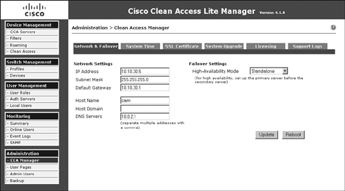
You can view the network configuration of NAM at Administration > CCA Manager. Figure 10-3 shows the network configuration page of NAC Appliance Manager in this sample topology (see Figure 10-1).
Figure 10-3. Manager Network Configuration Page
Step 5: Adding NAC Appliance Server to NAC Appliance Manager
You can add NAC Appliance Server by going to Device Management > CCA Servers > New Server. Figure 10-4 shows the add new server page.
Figure 10-4. Add New Server Page
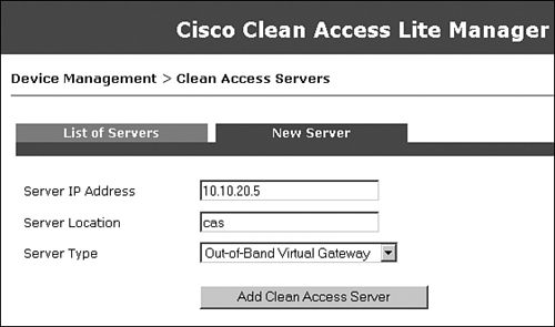
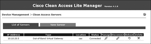
Figure 10-5 shows that NAC Appliance Server has been added in OOB Virtual Gateway mode.
Figure 10-5. List of Servers Page
Step 6: Editing Network Settings on NAC Appliance Server
Go to Device Management > CCA Servers > Manage > Network > IP. You will see a check box for Set Management VLAN ID. This is usually a source of a lot of confusion. By default, this option is not enabled. With this option disabled, when the NAC Appliance Server is initiating traffic and sending out of the trusted port, it sends the packets untagged. Therefore, when those packets reach the switch, it determines that the packets were received on the native VLAN and forwards them in that VLAN toward the destination. If this option is enabled and a VLAN ID is entered, when NAC Appliance initiates traffic, it sends the packets tagged with that VLAN ID. When the switch receives those packets, it determines them to be in that tagged VLAN. Therefore, as long as the configurations on the switch and NAC Appliance Server match, you are okay. If there is a mismatch between these configurations, you could blackhole your NAS traffic and be unable to manage NAS from NAM.
In this example, the NAS trusted port (eth0) is connected to Fa1/0/3, which is an 802.1q trunk link. Therefore, the switch expects to receive traffic from the NAS management as 802.1q-tagged traffic. So, in the Network Settings page of NAS, you should enable the option Set Management VLAN ID and enter 20 because VLAN 20 is the NAS management VLAN. Figure 10-6 shows the network configuration page of NAC Appliance Server in the sample topology.
Figure 10-6. Server Network Configuration Page

You will notice that you have configured the same IP for both the trusted and untrusted interfaces. Remember that in Virtual Gateway mode, NAC Appliance Server acts as a pure Layer 2 device. Therefore, this device can have only one IP: its management IP. NAC Appliance assumes that its management IP is the IP configured on the trusted port. The IP that you configure on the untrusted port has no relevance. You must configure the same IP on both the trusted and untrusted interfaces.
Step 7: Configuring VLAN Mapping
In OOB Virtual Gateway mode Central deployment, you want the user traffic on the untrusted VLAN to go through NAC Appliance Server before hitting the user's default gateway. The untrusted VLAN is also called the authentication VLAN (auth VLAN for short) in OOB mode. To achieve this traffic flow, NAC Appliance Server performs VLAN mapping. You configure VLAN mapping on NAC Appliance Server such that the untrusted VLAN is mapped to a trusted VLAN. This allows users on the untrusted side to reach their default gateway on the trusted side through NAC Appliance Server. NAC Appliance Server is bridging the two VLANs.
Of course, before users are bridged, they are stopped by NAC Appliance Server for authentication and posture assessment. By default, the one exception is that the users' DNS and DHCP requests are let through prior to authentication. In this example, traffic from untrusted VLAN 110 is mapped to trusted VLAN 10 (see Figure 10-1). Figure 10-7 shows the VLAN mapping configuration page found by navigating to Device Management > Clean Access Servers > 10.10.20.5 > Advanced > VLAN Mapping.
Figure 10-7. VLAN Mapping Configuration Page

Enable VLAN mapping and click the Update button. Configure the untrusted VLAN to be VLAN 110 and the trusted VLAN to be VLAN 10. After you enable and configure VLAN mapping, you can enable interface Fa1/0/4 also. When VLAN mapping is configured, NAC Appliance Server drops all Layer 2 control traffic, including bridge protocol data units, Cisco Discovery Protocol, and so on.
Step 8: Configuring Managed Subnets
It is extremely important to understand the concept of Managed Subnets when NAC Appliance Server is configured to be in Virtual Gateway mode. Figure 10-8 shows the sample network topology.
Figure 10-8. Sample Network Topology
The untrusted interface IP is of no relevance. When the user connects to the network and moves to the untrusted VLAN, the NAC Appliance Agent on the user's machine starts sending discovery packets to the IP address of NAC Appliance Manager. On their way to NAC Appliance Manager, the packets pass through and are intercepted by NAC Appliance Server. NAC Appliance Server has to respond to these packets, but to be able to do so, it must have an Address Resolution Protocol (ARP) entry for the sending client. Therefore, it has to send out an ARP request first. However, it cannot use the untrusted interface's IP as the source for the ARP request. In addition, NAC Appliance Server has to send the ARP request out the correct untrusted VLAN.
This is achieved by configuring managed subnets on NAC Appliance Server. Think of managed subnets as you would think of subinterfaces on routers. Figure 10-9 shows a sample managed subnet configuration page.
Figure 10-9. Managed Subnet Page
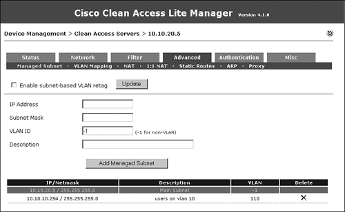
In this example, users on the untrusted network will be on VLAN 110. Because VLAN 110 is mapped to VLAN 10 on the trusted network, the users on VLAN 110 will actually get an IP address from the DHCP server on VLAN 10. The managed subnet that you configure here will be in the VLAN 10 subnet scope; however, it will have a VLAN ID of VLAN 110 because you want the ARP request to go out the untrusted side VLAN 110.
The term managed subnet is a little misleading. It really should be managed subnet interface. When you configure a managed subnet, make sure that you configure an IP address and not a subnet address. This is so that the ARP request that the NAC Appliance Server sends out has a valid source IP address. In this example, managed subnet 110 has an IP address of 10.10.10.254. You can see from Figure 10-9 that VLAN –1, which is the management VLAN 20, has an IP address of 10.10.20.5. –1 is a variable that maps to the VLAN configured on the eth0 trusted interface. All managed subnet IP addresses must be excluded from your DHCP server's address scopes.
Step 9: Configuring a Switch Group
This step is optional. A preconfigured Default group is already present. When you add switches to be managed by NAC Appliance Manager, they are added to the Default group. You can configure additional groups and then add the switches to a particular group. By doing so, when you list the switches, you can list them by group. This step is useful if you have a large number of switches to be managed by NAC Appliance. In this example, you will configure a group called cat3750. This is done by navigating to Switch Management > Profiles > Group, as shown in Figure 10-10.
Figure 10-10. Adding a Switch Group

Step 10: Configuring a Switch Profile
A switch profile is configured to define how NAC Appliance Manager communicates with the switches. When you add switches to be managed by NAC Appliance Manager, you configure which profile the switch belongs to. You must add a switch profile for each Cisco switch model you want to support. Figure 10-11 shows a profile for the sample switch, a 3750. This page can be accessed by navigating to Switch Management > Profiles > Switch > New.
Figure 10-11. Creating Switch Profiles

Make sure that you configure the switch model, SNMP port, and the SNMP read/write community strings to match the configuration on the switch.
Step 11: Configuring a Port Profile
A port profile is applied to a port to determine whether and how the port is controlled by NAC Appliance. You can configure the authentication VLAN, the default access VLAN, and the VLAN assignment method using a port profile. In the configuration shown in Figure 10-12, for the Access VLAN field, User Role VLAN has been chosen from the drop-down menu. This means that when a user is authenticated and healthy, the VLAN to which the user is moved will be decided by user role. The page shown in Figure 10-12 can be accessed by navigating to Switch Management > Profiles > Port > New.
Figure 10-12. Port Profile Configuration Page

The Generate Event Logs When There Are Multiple MAC Addresses Detected on the Same Switch Port option has been enabled so that you will know whether an end user has connected a hub or an unmanaged switch behind the NAC-controlled switch.
The Remove Out-of-Band Online User When SNMP Linkdown Trap Is Received option has been enabled so that if the user machine disconnects from the switch port, the user will be logged off from NAC Appliance.
If a user connects his machine from behind an IP phone, when that user disconnects, the switch will not detect a linkdown, and therefore will not log the user off from NAC Appliance. The Remove Other Out-of-Band Online Users on the Switch Port When a New User Is Detected on the Same Port option has been enabled so that if a new user is detected on a port, NAC Appliance will automatically log off the old user.
If your clients will be plugged into IP phones, you must check the Remove Out-of-Band Online User Without Bouncing the Port option. This ensures that the IP phone is not disconnected every time a host disconnects.
Step 12: Configuring the SNMP Receiver
The SNMP receiver configuration must match the SNMP configuration on the NAC-controlled switches. The SNMP receiver receives and responds to SNMP traps sent by switches. The SNMP receiver page shown in Figure 10-13 can be accessed by navigating to Switch Management > Profiles > SNMP Receiver > SNMP Trap.
Figure 10-13. SNMP Receiver Configuration Page

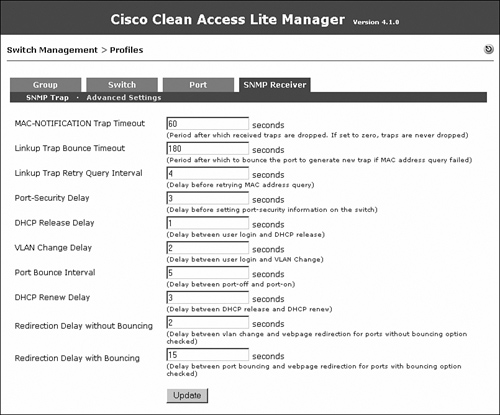
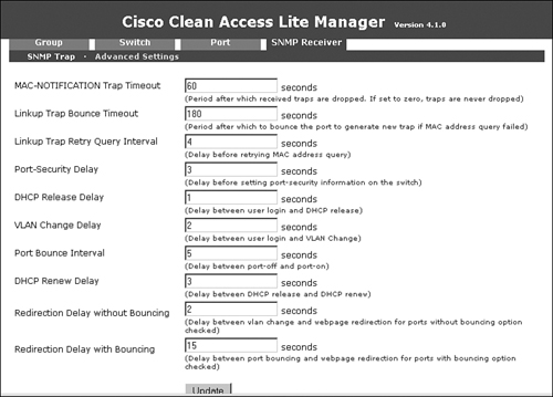
Advanced settings with which you can tweak different timers are also available. They are accessed by navigating to Switch Management > Profiles > SNMP Receiver > Advanced Settings. Tweaking the timers is not usually required unless there is unexpected latency in the switch and the NAC Appliance Manager communication. Figure 10-14 shows the advanced settings configuration page.
Figure 10-14. SNMP Receiver Advanced Settings
Step 13: Adding a Switch to NAC Appliance Manager
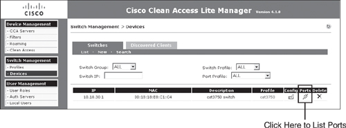
Now you need to add the individual switches. To do this, navigate to Switch Management > Devices > Switches > New. Choose the appropriate switch profile and switch group. Most of the time it is best to set the default port profile to Uncontrolled. This instructs NAC Appliance not to control any switch port until told to. Finally, type in the IP address of the switch and click Add. Figure 10-15 shows the addition of the sample switch.
Figure 10-15. Adding a Switch to NAC Appliance

Step 14: Configuring Ports to Be Managed by NAC
To configure the control of switch ports, click the Ports icon, shown in Figure 10-16, for the switch.
Figure 10-16. List of Switches
As shown in Figure 10-17, clicking the Ports icon lists all the ports available on that switch and the configuration of each.
Figure 10-17. Ports List

Because the user PC is connected on Fa1/0/5, change the profile for port Fa1/0/5 to the NAC_controlled port profile and click Update. When you click the Update button, NAC Appliance Manager adds the command snmp trap mac-notification added to the Fa1/0/5 interface configuration. This configuration change is made to the running configuration of the switch.
Step 15: Configuring User Roles
You will configure three user roles: Guest, Consultant, and Employee. In the user role page, you will also configure the OOB user role VLAN—this is the VLAN that the switch port will be assigned to when a user belonging to that user role completes the NAC process. Note that the configuration of any IPsec, VPN, or roaming parameters is not relevant anymore. These are deprecated features soon to be removed from the solution. Figure 10-18 shows the user role creation for Guest.
Figure 10-18. New User Role Configuration Page—Guest
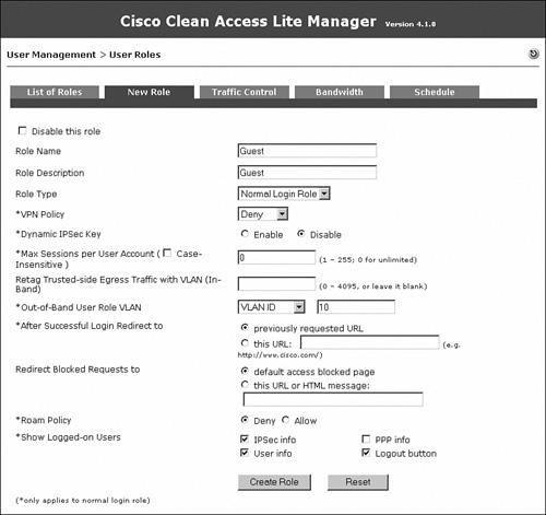
Figure 10-19 shows the user role creation for Consultant.
Figure 10-19. New User Role Configuration Page—Consultant

Figure 10-20 shows the user role creation for Employee.
Figure 10-20. New User Role Configuration Page—Employee

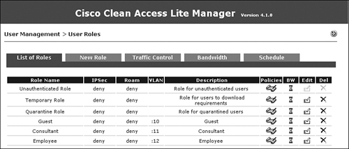
Figure 10-21 shows all the user roles.
Figure 10-21. List of Roles Page

Step 16: Configuring User Authentication on the Local Database
Add two local users to the NAC Appliance local database. One will be an employee and the second will be a consultant. These local user accounts will be used for testing purposes. In a production environment, you should configure an LDAP, Kerberos, or RADIUS server instead. Local users should generally be used only for testing and guest access. Figure 10-22 shows creation of a consultant user who is a member of the Consultant role.
Figure 10-22. New Local User Configuration Page—Consultant
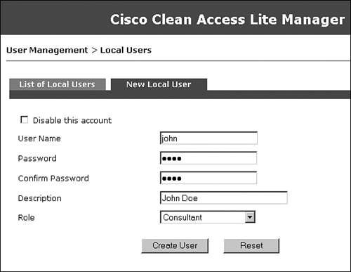
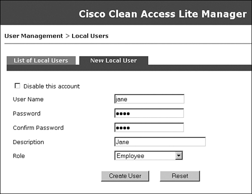
Figure 10-23 shows creation of an employee user who is a member of the Employee role.
Figure 10-23. New Local User Configuration Page—Employee
Step 17: Testing Whether OOB and User Role–Based VLAN Assignment Works
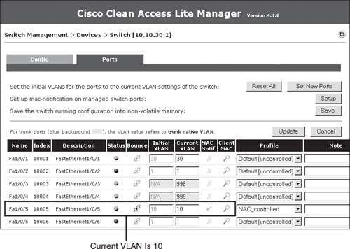
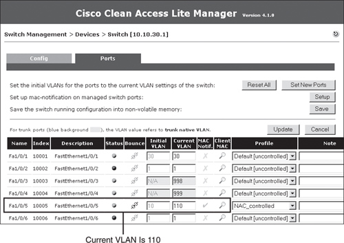
If you go to Switch Management > Device > Switches > List > 10.10.30.1 > Ports, you will see that interface Fa1/0/5, the client port, is currently on VLAN 10. This is shown in Figure 10-24.
Figure 10-24. List of Ports
Now go ahead and connect a laptop to interface Fa1/0/5. You see in Figure 10-25 that the port was immediately moved to the untrusted VLAN 110. This is because that port profile had the auth (untrusted) VLAN set to VLAN 110.
Figure 10-25. List of Ports After Client Linkup
On the user PC, you will see that NAC Appliance Agent has popped up. Go ahead and put in the credentials for the user jane, as shown in Figure 10-26.
Figure 10-26. Clean Access Agent Authentication Popup

After you click Login, NAC Appliance determines that the user jane belongs to the Employee user role. NAC Appliance looks at the OOB user role VLAN configured under the Employee user role and moves the user's switch port Fa1/0/5 to VLAN 12. See Chapter 6, "Building a Cisco NAC Appliance Host Security Policy," for more information about user roles. Figure 10-27 shows the port Fa1/0/5 now in the access VLAN 12, as determined by the user role.
Figure 10-27. Port List—Access VLAN

Because you changed the VLAN of the user from VLAN 110 to VLAN 12 in this process, the subnet for the user also changed. Previously the user received an IP address from the VLAN 10 subnet scope. However, because the user is in VLAN 12 now, it must refresh its IP address. This can be done by configuring port bouncing. However, doing so is not recommended and not possible if you have IP phones. Instead, use the DHCP release/renew functionality built into Clean Access Agent and the web login applet. As a result, during the login process, you will see the Clean Access Agent screens shown in Figure 10-28 and Figure 10-29.
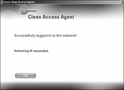
Figure 10-28. IP Refresh Dialog Box

Figure 10-29. IP Refresh Successful Dialog Box
The user will show up in the Online User list shown in Figure 10-30. This list is accessed by navigating to Monitoring > Online Users > Out-of-Band. If the OOB user is in quarantine, it shows up in the In-Band user list until it passes certification.
Figure 10-30. OOB Online Users List

Now if the user disconnects from the switch port, NAC Appliance removes the user from the online user list. NAC Appliance knows that the user disconnected because the switch is configured to send a linkdown SNMP trap to NAC Appliance Manager. Note that the port remains in VLAN 12. The port's VLAN does not change again until NAC Appliance Manager receives a linkup or MAC-notification trap on that port from the switch.
Another user, John, now connects to the same user port. The port immediately moves to the auth (untrusted) VLAN 110, as shown in Figure 10-31.
Figure 10-31. Switch Ports List—Untrusted

On the user's machine, Clean Access Agent pops up asking for authentication. Put in the credentials for the user john and click Login as shown in Figure 10-32.
Figure 10-32. Clean Access Agent Login

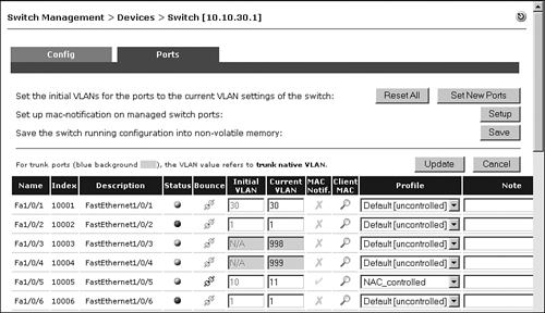
After the user is authenticated, NAC Appliance Manager determines that this user is a consultant and moves the user to VLAN 11. This is shown in the ports list of Figure 10-33 for the interface FastEthernet1/0/5. The Consultant user role is configured to use VLAN 11.
Figure 10-33. Switch Ports List—Consultant Role
The user shows up in the online user list as a Consultant, as shown in Figure 10-34.
Figure 10-34. Online User List—Consultant

Sample Design and Configuration for Layer 3 Out-of-Band Deployment
For Layer 3 out-of-band deployment, consider the topology in Figure 10-35.
Figure 10-35. Sample Layer 3 OOB Network Topology

Note
Figure 10-35 is the basis for this example and is referred to several times throughout the following text. It will be helpful to bookmark this page or note the page number for easy reference as you read through this example.
You can see from the topology in Figure 10-35 that NAC Appliance Server is connected to the central switch. There is a network cloud between the central and edge switch. This cloud could be just a routed campus network, or it could be a WAN connection. The main point in this scenario is that the users are multiple routing hops away from NAC Appliance Server; therefore, it is Layer 3 OOB mode. In this example, the clients are no longer Layer 2 adjacent to NAC Appliance Server they are now Layer 3 adjacent to it.
With Out-of-Band mode, the goal is to move the user to the untrusted VLAN when that user connects to the network. While the user is in the untrusted VLAN, you want to be able to carry out authentication, posture assessment, and remediation for the user. When the user is in the untrusted VLAN, NAC Appliance Server acts as the enforcement device and communicates with NAC Appliance agent for user authentication, posture assessment, and remediation.
In Out-of-Band mode, NAC Appliance Server has to be able to determine the IP and MAC addresses of the user. When the user is Layer 2 adjacent to NAC Appliance Server (L2OOB) and the user's packets reach NAC Appliance Server, NAS can determine the source IP and MAC addresses of the user from those packets. When the user is one or more hops away from NAC Appliance Server, previous hop routers overwrite the source MAC address of the packets reaching NAS. As a result, NAC Appliance Server is unable to determine the MAC address of the user from the packets.
NAC Appliance Agent from release 4.0.0.0 onward sends the information regarding the user's MAC address and IP to NAC Appliance Server. For users who don't have NAC Appliance Agent, the web login page can be configured to use ActiveX or Java applet controls to get the same information from the user's device.
Chapter 4 explains the various traffic control methods for Layer 3 OOB. In the following example, you will see how to configure Layer 3 OOB using ACLs. As shown in the topology, NAC Appliance Server is configured to be in Real IP Gateway mode. This makes NAC Appliance Server into a router and requires that the untrusted port (eth1) of NAC Appliance Server has a unique IP address and subnet. The following sections form a step-by-step method for configuring Layer 3 OOB deployments using ACLs.
Step 1: Configuring the Switches
The sample topology (see Figure 10-35) has a central switch and an edge switch, both of which are Catalyst 3750 series switches running code 12.2 (25) SEE or later.
Configuring the Central Switch
The first step is configuring the central switch. You have to complete the following configuration steps at a minimum:
- Configure Virtual LAN Trunking Protocol (VTP) and VLANs
- Configure SVIs
- Configure the ports that NAC Appliance Manager and NAC Appliance Server connect to
After these steps are completed, you might have to configure additional interfaces and features if doing so is necessary for your environment.
Configuring VTP and VLANs
It is a best practice campus design not to enable VTP Server mode on switches. You should instead set VTP to Transparent mode, which effectively disables VTP operation. The ip routing command allows the switch to act as a router as well. Example 10-11 shows the VTP and VLAN central switch configuration as it pertains to the sample network topology.
Example 10-11. Central Switch VTP and VLAN Configuration
vtp domain cisco
vtp mode transparent
ip routing
!
vlan 20
name NAS_Trusted
!
vlan 21
name NAS_Untrusted
!
vlan 30
name NAM_mgmt
!
Configuring SVIs
Next configure the switch virtual interfaces on the central switch. An SVI is a Layer 3 virtual interface that is mapped to a VLAN for routing traffic through a switch. Example 10-12 shows the central switch configuration for SVIs in the sample topology (see Figure 10-35).
Example 10-12. Central Switch SVI Configuration
interface Vlan20
ip address 10.10.20.1 255.255.255.0
description Server Trusted
!
interface Vlan21
ip address 10.10.21.1 255.255.255.0
description Server Untrusted
!
interface Vlan30
ip address 10.10.30.1 255.255.255.0
description Manager eth0
!
Configuring Fa1/0/1—The Interface Connecting NAC Appliance Manager
Configure this interface to be an access port in VLAN 30. The Central switch configuration is shown in Example 10-13.
Example 10-13. Switch Configuration of Manager port
interface FastEthernet1/0/1
description Manager
switchport access vlan 30
switchport mode access
spanning-tree portfast
!
Configuring Fa1/0/1—The Interface Connecting the Trusted Port of NAC Appliance Server
Configure this NAC Appliance Server interface, eth0, as an access port in VLAN 20. Example 10-14 shows the switch configuration.
Example 10-14. Switch Configuration of Trusted Server Port
interface FastEthernet1/0/3
description Server Trusted eth0
switchport access vlan 20
switchport mode access
spanning-tree portfast
!
Configuring Fa1/0/4—The Interface Connecting the Untrusted Port of NAC Appliance Server
Configure this interface, eth1, as an access port in VLAN 21, as shown in Example 10-15.
Example 10-15. Switch Configuration of Untrusted Server Port
interface FastEthernet1/0/4
description Server Untrusted eth1
switchport access vlan 21
switchport mode access
spanning-tree portfast
!
Configuring the Edge Switch
Next configure the edge switch. You have to complete the following configuration steps at a minimum:
- Configure VTP and VLANs.
- Configure ACLs on the switch for added security and traffic control.
- Configure SVIs.
- Configure a DHCP server; in this sample case, you are using the switch as the DHCP server.
- Configure the client ports.
- Configure SNMP on the switch.
After these steps are completed, you might have to configure additional interfaces and features if doing so is necessary for your environment.
Configuring VTP and VLANs
Using VTP is not recommended, and you accomplish this by setting it to Transparent mode. You enable IP routing by using the ip routing command. Example 10-16 shows the switch configuration for VTP and VLANs as it pertains to the sample network topology (see Figure 10-35).
Example 10-16. Edge Switch VTP and VLAN Configuration
vtp domain cisco
vtp mode transparent
ip routing
!
vlan 10
name guest
!
vlan 11
name consultant
!
vlan 12
name employee
!
vlan 110
name untrusted
!
vlan 22
name switch_mgmt
!
Configuring Access Control Lists
In this design, the enforcement piece has moved from NAC Appliance Server to the edge switch. You will configure ACLs on the authentication/untrusted VLAN so as to allow traffic to NAC Appliance Server, remediation servers, DHCP server, Active Directory server (if using AD SSO), and any other resources required for remediation purposes. When the user is in the untrusted VLAN, NAC Appliance Agent starts sending discovery packets that will be allowed by the ACL. After NAC Appliance Server gets the NAC Appliance Agent discovery packets, it will know that there is a new host connected to the network. It can then prompt the user for authentication and posture assessment.
For posture remediation, NAC Appliance Agent facilitates remediation by directing the user to go to the remediation resources. Access to these resources has been allowed by the ACLs. So, a user goes through the complete NAC process while in the untrusted VLAN. The ACLs block access to anything else on the network, thus preventing noncompliant users from getting access to other network resources. Example 10-17 shows a sample of the access list that you will configure for the untrusted VLAN 110.
Example 10-17. Untrusted VLAN 110 ACL
ip access-list 100 permit ip any host 10.10.21.5
ip access-list 100 permit udp any any eq domain
ip access-list 100 permit tcp any any eq domain
ip access-list 100 permit udp any any eq 67
ip access-list 100 permit udp any any eq 68
ip access-list 100 permit ip any host [wsus, av, etc]
Host 10.10.21.5 is NAC Appliance Server. This ACL allows the NAC Appliance Agent discovery packets to reach NAS. Remaining ACLs allow DNS (domain), DHCP (port 67), and access to the WSUS server, antivirus server, and other remediation resources.
In addition to the ACL on the untrusted VLAN, you have to configure an ACL on the trusted VLANs. This is because NAC Appliance Agent is going to send discovery packets every 5 seconds, continuously. So, even when the user is moved to the trusted access VLAN, NAC Appliance Agent continues to send the discovery packets. You want to prevent those packets from reaching NAC Appliance Server. To do so, configure the following ACL on the trusted VLANs:
access-list 101 deny ip any host 10.10.21.5
access-list 101 permit ip any any
This access list will block any traffic from reaching NAC Appliance Server when the user is on the trusted VLAN. You can optionally add to the preceding ACL to further control client traffic. For example, you might create an ACL, specific to consultants, which allows them only limited access to your network. You would then apply this ACL to the consultant VLAN 11.
Configuring SVIs
Example 10-18 shows the switch configuration of the Layer 3 SVI interfaces. Notice the command ip access-group 100 in or ip access-group 101 in on the SVI interfaces. This command applies to the SVI an access list that can limit the access of clients. You can find the access list definitions in the "Configuring Access Control Lists" section.
Example 10-18. Edge Switch SVI Configuration
interface Vlan10
description Guest
ip address 10.10.10.1 255.255.255.0
ip access-group 101 in
!
interface Vlan11
description Consultant
ip address 10.10.11.1 255.255.255.0
ip access-group 101 in
!
interface Vlan12
description Employee
ip address 10.10.12.1 255.255.255.0
ip access-group 101 in
!
interface Vlan110
description Untrusted
ip address 10.10.110.1 255.255.255.0
ip access-group 100 in
!
interface Vlan22
description Switch Management
ip address 10.10.22.2 255.255.255.0
!
Configuring the Switch as a DHCP Server
Almost every network needs a DHCP server. In the sample topology (see Figure 10-35), you will configure the switch to act as the DHCP server. The switch is configured to act as the DHCP server for the user VLANs 10, 11, and 12, and the untrusted VLAN 110. Example 10-19 shows the edge switch DHCP configuration.
Example 10-19. Edge Switch DHCP Server Configuration
ip dhcp excluded-address 10.10.10.1
ip dhcp excluded-address 10.10.10.254
ip dhcp excluded-address 10.10.11.1
ip dhcp excluded-address 10.10.11.254
ip dhcp excluded-address 10.10.12.1
ip dhcp excluded-address 10.10.12.254
ip dhcp excluded-address 10.10.110.1
ip dhcp excluded-address 10.10.110.254
!
ip dhcp pool vlan10
network 10.10.10.0 255.255.255.0
default-router 10.10.10.1
dns-server 192.168.35.2
domain-name cisco.com
!
ip dhcp pool vlan11
network 10.10.11.0 255.255.255.0
default-router 10.10.11.1
dns-server 192.168.35.2
domain-name cisco.com
!
ip dhcp pool vlan12
network 10.10.12.0 255.255.255.0
default-router 10.10.12.1
dns-server 192.168.35.2
domain-name cisco.com
!
ip dhcp pool vlan110
network 10.10.110.0 255.255.255.0
default-router 10.10.110.1
dns-server 192.168.35.2
domain-name cisco.com
!
Configuring Fa1/0/5—The Interface Connecting the Host
Configuration of the client ports is straightforward; they just need to be set up as access ports. In the sample topology, the client port Fa1/0/5 is configured to be an access port in VLAN 10, as shown in Example 10-20.
Example 10-20. Edge Switch Configuration—Client Port
interface FastEthernet1/0/5
description client port
switchport access vlan 10
switchport mode access
spanning-tree portfast
!
Configuring SNMP
The switch must be configured with SNMP MAC-notification traps and linkdown traps. The MAC-notification trap is used to detect a new user on the network and to trigger the NAC process. The linkdown trap is used to detect that the user disconnected from the network. Example 10-21 shows the necessary SNMP configuration on the edge switch. An access list 10 is applied to the SNMP configuration to increase security. This allows only NAC Appliance Manager to speak SNMP with the switch.
Example 10-21. Edge Switch SNMP Configuration
snmp-server community public RO 10
snmp-server community private RW 10
snmp-server enable traps snmp linkdown
snmp-server enable traps MAC-Notification
snmp-server host 10.10.30.5 snmpv2c public
access-list 10 permit ip 10.10.30.5
Step 2: Configuring NAC Appliance Manager
On NAC Appliance Manager, you have to do some basic configuration using the configuration script. From the NAC Appliance Manager CLI, you must type in service perfigo config. Initially, you can access the CLI by putting a keyboard and monitor on NAC Appliance Manager or via the serial port (38400bps). After NAC Appliance Manager has an IP address, the CLI can be accessed via SSH. Example 10-22 shows the configuration setup script.
Example 10-22. Running the Configuration Script on the Manager
Fedora Core release 4 (Stentz)
Kernel 2.6.11-perfigo on an i686
cam login: root
Password:
[root@cam ~]# service perfigo config
Welcome to the Cisco Clean Access Manager quick configuration utility.
Note that you need to be root to execute this utility.
The utility will now ask you a series of configuration questions.
Please answer them carefully.
Cisco Clean Access Manager, (C) 2006 Cisco Systems, Inc.
Configuring the network interface:
Please enter the IP address for the interface eth0 [10.2.0.15]: 10.10.30.5
You entered 10.10.30.5. Is this correct? (y/n)? [y]
Please enter the netmask for the interface eth0 [255.255.255.0]:
You entered 255.255.255.0. Is this correct? (y/n)? [y]
Please enter the IP address for the default gateway [10.2.0.1]: 10.10.30.1
You entered 10.10.30.1. Is this correct? (y/n)? [y]
Please enter the hostname [cam1]: nam
You entered nam. Is this correct? (y/n)? [y]
Please enter the IP address for the name server: [192.168.10.1]: 10.10.30.6
You entered 10.10.30.6. Is this correct? (y/n)? [y]
Would you like to change shared secret? (y/n)? [y]
Please remember to configure the Clean Access Server with the same string.
Please enter the shared secret between Clean Access Server
You entered: cisco123
Is this correct? (y/n)? [y]
>>> Configuring date and time:
The timezone is currently set to:America/Los_Angeles
Would you like to change this setting? (y/n)? [y] n
Current date and time hh:mm:ss mm/dd/yy [01:01:01 01/01/07]: 01:20:00 01/01/07
You entered 01:20:00 01/01/07 Is this correct? (y/n)? [y]
Mon Jan 01 01:20:00 PST 2007
You must generate a valid SSL certificate in order to use the Clean Access Manager's
secure web console.
Please answer the following questions correctly.
Information for a new SSL certificate:
Enter fully qualified domain name or IP: 10.10.30.5
Enter organization unit name: nacapp
Enter organization name: cisco
Enter city name: san jose
Enter state code: ca
Enter 2 letter country code: us
You entered the following:
Domain: 10.10.30.5
Organization unit: nacapp
Organization name: cisco
City name: san jose
State code: ca
Country code: us
Is this correct? (y/n)? [y]
Generating SSL Certificate...
CA signing: /root/.tomcat.csr -> /root/.tomcat.crt:
CA verifying: /root/.tomcat.crt <-> CA cert
/root/.tomcat.crt: OK
Done
For security reasons, it is highly recommended that you change the default passwords
for the root user.
User: root
Changing password for user root.
New UNIX password:
Retype new UNIX password:
passwd: all authentication tokens updated successfully.
Changes require a RESTART of Clean Access Manager.
Configuration is complete.
[root@cam1 ~]# service perfigo reboot
Step 3: Configuring NAC Appliance Server
On NAC Appliance Server, you must again perform some basic configuration using the configuration script. From the NAC Appliance Server CLI, type in service perfigo config. Initially, you can access the CLI by putting a keyboard and monitor on NAC Appliance Manager or via the serial port (38400bps). After NAC Appliance Server has an IP address, the CLI can be accessed via SSH. Example 10-23 shows the configuration setup script.
Example 10-23. Configuring the NAS via CLI
[root@cas ~]# service perfigo config
Welcome to the Cisco Clean Access Server quick configuration utility.
Note that you need to be root to execute this utility.
The utility will now ask you a series of configuration questions.
Please answer them carefully.
Cisco Clean Access Server, (C) 2006 Cisco Systems, Inc.
Configuring the network interfaces:
Please enter the IP address for the interface eth0 [10.2.0.15]: 10.10.20.5
You entered 10.10.20.5. Is this correct? (y/n)? [y]
Please enter the netmask for the interface eth0 [255.255.255.0]:
You entered 255.255.255.0. Is this correct? (y/n)? [y]
Please enter the IP address for the default gateway [10.2.0.1]: 10.10.20.1
You entered 10.10.20.1. Is this correct? (y/n)? [y]
[Vlan Id Passthrough] for packets from eth0 to eth1 is disabled.
Would you like to enable it? (y/n)? [n]
[Management Vlan Tagging] for egress packets of eth0 is disabled.
Would you like to enable it? (y/n)? [n]
Please enter the IP address for the untrusted interface eth1 [10.2.0.15]: 10.10.21.5
You entered 10.10.20.5. Is this correct? (y/n)? [y]
Please enter the netmask for the interface eth1 [255.255.255.0]:
You entered 255.255.255.0. Is this correct? (y/n)? [y]
Please enter the IP address for the default gateway [10.2.0.1]: 10.10.21.1
You entered 10.10.20.1. Is this correct? (y/n)? [y]
[Vlan Id Passthrough] for packets from eth1 to eth0 is disabled.
Would you like to enable it? (y/n)? [n]
[Management Vlan Tagging] for egress packets of eth1 is disabled.
Would you like to enable it? (y/n)? [n]
Please enter the hostname [cas1]: l3oobnas
You entered NAS1. Is this correct? (y/n)? [y]
Please enter the IP address for the name server: [192.168.10.1]: 10.10.30.6
You entered 10.10.30.6. Is this correct? (y/n)? [y]
Would you like to change shared secret? (y/n)? [y]
Please enter the shared secret: cisco123
You entered: cisco123
Is this correct? (y/n)? [y]
>>> Configuring date and time:
The timezone is currently set to:America/Los_Angeles
Would you like to change this setting? (y/n)? [y] n
Current date and time hh:mm:ss mm/dd/yy [01:01:01 01/02/07]: 01:55:00 01/01/07
You entered 01:55:00 01/02/07. Is this correct? (y/n)? [y]
Tues Jan 02 01:55:00 PST 2007
You must generate a valid SSL certificate in order to use the Clean Access Server's
secure web console.
Please answer the following questions correctly.
Information for a new SSL certificate:
Enter fully qualified domain name or IP: 10.10.20.5
Enter organization unit name: nacapp
Enter organization name: cisco
Enter city name: san jose
Enter state code: ca
Enter 2 letter country code: us
You entered the following:
Domain: 10.10.20.5
Organization unit: nacapp
Organization name: cisco
City name: san jose
State code: ca
Country code: us
Is this correct? (y/n)? [y]
Generating SSL Certificate...
CA signing: /root/.tomcat.csr -> /root/.tomcat.crt:
CA verifying: /root/.tomcat.crt <-> CA cert
/root/.tomcat.crt: OK
Done
For security reasons, it is highly recommended that you change the default password
for the root user.
User: root
Changing password for user root.
New UNIX password:
Retype new UNIX password:
passwd: all authentication tokens updated successfully.
Would you like to change the default password for the web console admin user
password? (y/n)? [y]
Please enter an appropriately secure password for the web console admin user.
New password for web console admin:
Confirm new password for web console admin:
Web console admin password changed successfully.
Configuration is complete.
[root@cas1 ~]# service perfigo reboot
Step 4: Logging In to NAC Appliance Manager
Open a browser and connect to NAM through a SSL connection. Type in the IP or domain name of the NAM (https://10.10.30.5). The default username is admin, and the default password is cisco123.
You can view the NAM configuration at Administration > CCA Manager, as shown in Figure 10-36.
Figure 10-36. NAC Appliance Manager Configuration Page

Step 5: Adding NAC Appliance Server to NAC Appliance Manager
You can add NAC Appliance Server by going to Device Management > CCA Servers > New Server, as shown in Figure 10-37. In the sample topology (see Figure 10-35), NAC Appliance Server is of type Out-of-Band Real-IP Gateway. Be sure to select the proper server type from the drop-down menu.
Figure 10-37. New Server Configuration Page
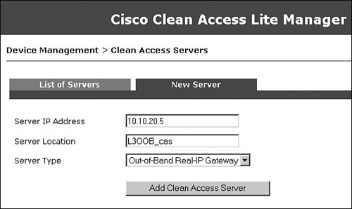
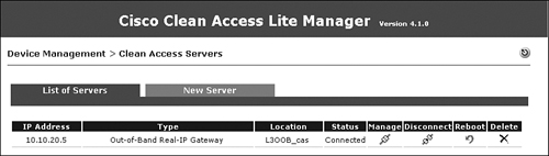
Figure 10-38 shows that NAC Appliance Server has been added in OOB Real-IP Gateway mode, and its status is connected.
Figure 10-38. Server List
Step 6: Editing Network Settings on NAC Appliance Server
In Figure 10-39, notice that Set Management VLAN ID is not enabled. This is because the switch ports to which NAC Appliance Server is connected are access ports, not 802.1q trunk ports. Therefore, you don't want NAS to tag any packets. In addition, the check box next to Enable L3 Support is checked. This allows NAC Appliance Server to communicate with clients that are Layer 2 adjacent or multiple routing hops away.
Figure 10-39. Server Network Configuration Page

Step 7: Configuring Static Routes
In this example, you don't have to configure any managed subnets. However, you will configure static routes. This is one difference between a Layer 2 OOB deployment and a Layer 3 OOB deployment.
Think of managed subnets as directly connected subnets for routers. So, for user subnets directly connected to NAC Appliance Server, you configure managed subnets.
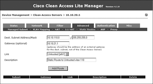
NAC Appliance Server does not support routing protocols. Therefore, for user subnets that are one or more hops away from NAC Appliance Server, you have to configure static routes. NAC Appliance Server communicates with the user device when the user is in the untrusted VLAN. So, you will configure static routes for the subnets associated with the untrusted VLANs, as shown in Figure 10-40. In this example, VLAN 110 (10.10.110.0/24) is the untrusted VLAN.
Figure 10-40. Adding a Static Route on NAC Appliance Server
Step 8: Configuring a Switch Group
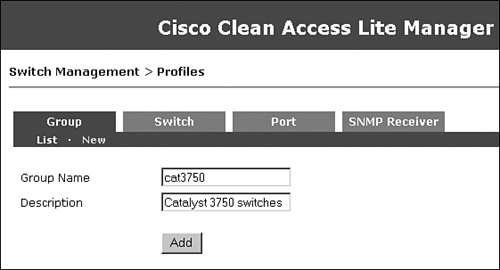
This step is optional. A preconfigured Default group is already present. When you add switches to be managed by the NAC Appliance Manager, they are added to the Default group. You can configure additional groups and then add the switches in a particular group. By doing this, when you list the switches, you can list them by group. This step is useful if you have a large number of switches to be managed by NAC Appliance. In this example, you will configure a group called cat3750, as shown in Figure 10-41.
Figure 10-41. Adding a Switch Group
Step 9: Configuring a Switch Profile
A switch profile is configured to define how NAC Appliance Manager communicates with the switches. When you add the switches to be managed by NAC Appliance Manager, you will configure which profile the switch belongs to. You must add a switch profile for each model of Cisco switch you manage. Figure 10-42 shows the switch profile configuration page.
Figure 10-42. Adding a Switch Profile

Make sure that you configure the switch model, the SNMP port, and the SNMP read/write community strings to match the configuration on each switch.
Step 10: Configuring a Port Profile
A port profile is applied to a port to determine whether it is controlled by NAC Appliance. You can configure the authentication VLAN, default access VLAN, and VLAN assignment method using port profiles. Remember that the authentication VLAN is the same as the untrusted VLAN or quarantine VLAN. The access VLAN is the trusted side VLAN. In the configuration (see Figure 10-35) for the Access VLAN field, User Role VLAN has been chosen from the drop-down menu. This means that when the user is authenticated and healthy, the VLAN to which the user is moved is determined by user role. Figure 10-43 shows the port profile configuration page.
Figure 10-43. Port Profile Configuration Page
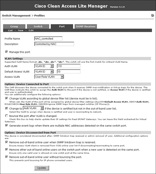
The Generate Event Logs When There Are Multiple MAC Addresses Detected on the Same Switch Port option is enabled so that you will know if an end user has connected a hub or an unmanaged switch behind the NAC-controlled switch.
The Remove Out-of-Band Online User When SNMP Linkdown Trap Is Received option is enabled so that if the user machine is disconnected from the switch port, the user will be logged off from NAC Appliance.
In a scenario in which a user connects his machine from behind an IP phone, when the user disconnects, the switch will not detect a linkdown and therefore will not log off the user from NAC Appliance. The Remove Other Out-of-Band Online Users on the Switch Port When a New User Is Detected on the Same Port option is enabled so that if a new user is detected on a port, NAC Appliance will automatically log off the old user. In addition, the Remove Out-of-Band Online User Without Bouncing the Port option is checked. This is required if clients will be behind IP phones.
Step 11: Configuring the SNMP Receiver
The SNMP receiver configuration must match the SNMP configuration on the NAC-controlled switches. The SNMP receiver receives and responds to SNMP traps sent by switches. Figure 10-44 shows the SNMP receiver configuration for the sample topology.
Figure 10-44. SNMP Receiver Configuration Page

Advanced settings with which you can tweak different timers are also available, as shown in Figure 10-45. Tweaking the timers is not required unless there is unexpected latency in the switch and the NAC Appliance Manager communication.
Figure 10-45. SNMP Receiver Advanced Settings
Step 12: Adding the Switch to NAC Appliance Manager
For NAC Appliance to manage a switch, the switch must first be added (see Figure 10-46). This page can be found by navigating to Switch Management > Devices > New.
Figure 10-46. Add a New Switch Configuration Page

You must choose the appropriate switch profile and switch group. Make sure that you choose Default Port Profile as Uncontrolled. Put in the IP address of the switch and click Add.
Step 13: Configuring Ports to Be Managed by NAC Appliance
Now that the switch has been added, NAC Appliance dynamically learns all its ports. To view them, click the Ports icon for the switch, as shown in Figure 10-47. Doing so lists all the ports available on that switch, as shown in Figure 10-48.
Figure 10-47. Switches List

Figure 10-48. Port List

Because the user PC is connected on Fa1/0/5, change the profile for port Fa1/0/5 to the NAC_controlled port profile and click Update. When you click the Setup button, NAC Appliance Manager adds the command snmp trap mac-notification added to the Fa1/0/5 interface configuration. This configuration change is made to the running configuration of the switch. To save it to the startup-config, click the Save button.
Step 14: Configuring User Roles
For the sample topology, you will configure three user roles: Guest, Consultant, and Employee. In the user role page, you will define the OOB user role VLAN. This is the VLAN to which the switch port will be assigned when a user belonging to the user role completes the NAC process. See Figure 10-35 for a list of these VLAN assignments. Remember that all references to roaming, IPsec, and VPN on the user role configuration page should be ignored because they are deprecated features. Figure 10-49 shows the user role creation for Guest.
Figure 10-49. Adding a User Role—Guest
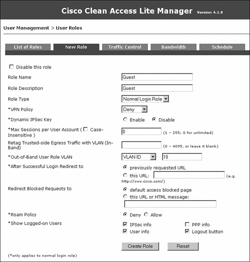
Figure 10-50 shows the user role creation for Consultant.
Figure 10-50. Adding a User Role—Consultant
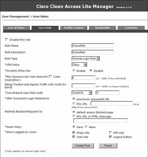
Figure 10-51 shows the user role creation for Employee.
Figure 10-51. Adding a User Role—Employee

Figure 10-52 shows all the user roles.
Figure 10-52. User Role List
Step 15: Configuring User Authentication on the Local Database
Add two local users to the NAC Appliance local database: an employee and a consultant. These local user accounts will be used for testing purposes. In a production environment, you should configure an LDAP, Kerberos, or RADIUS server instead of a local user database. Local users should generally be used only for testing and guest access. Figure 10-53 shows the creation of a Consultant user.
Figure 10-53. Adding a Local User—Consultant
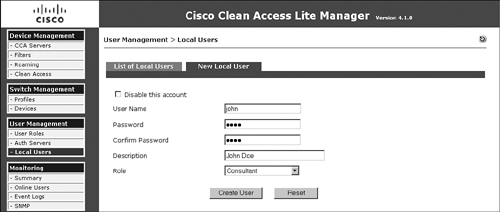
Figure 10-54 shows the creation of an Employee user.
Figure 10-54. Adding a Local User—Employee

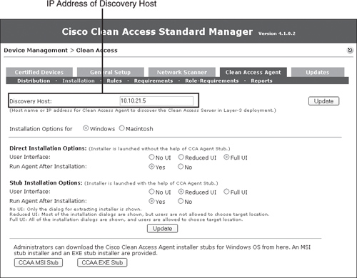
Step 16: Changing the Discovery Host
NAC Appliance Agent sends discovery packets to discover the NAC Appliance Server so that it can start communicating with it and begin the NAC process. These packets are sent on UDP port 8905 and 8906.
NAC Appliance Server listens on the UDP ports 8905 and 8906. So, when it receives packets from NAC Appliance Agent on these ports, it knows that a new host has connected to the network and instructs NAC Appliance Agent to pop up and challenge the user for authentication. The NAC Appliance Server doesn't forward these packets out on the trusted network.
The packets on UDP 8905 are sent to the default gateway of the user device. Therefore, if a NAC Appliance Server is Layer 2 adjacent to the user, the NAC Appliance Agent packets will reach NAS.
NAC Appliance Agent sends the discovery packets on port 8905 to the discovery host configured on NAC Appliance Manager. By default, the discovery host is the IP address of NAM. This is because NAM always exists on the trusted network, and for a user on the untrusted network to reach a host on the trusted network, it has to go through NAS and therefore will discover NAS.
In this design, you are not forcing all user traffic to reach NAC Appliance Server. Adding a technology such as policy-based routing, virtual routing and forwarding, or generic routing encapsulation would force traffic through NAC Appliance Server. You are using VLAN ACLs that do not force traffic back to NAC Appliance Server, but only restrict where it can go. Therefore, you must change the discovery host from NAC Appliance Manager (the default) to be the untrusted port IP of NAC Appliance Server, as shown in Figure 10-55. Doing so ensures that the NAC Appliance Agent discovery packets will reach NAC Appliance Server.
Figure 10-55. Changing Discovery Host
Step 17: Configuring the Web Login Page
You have to configure the web login page for users who don't use NAC Appliance Agent. The Login Page edit screen is shown in Figure 10-56.
Figure 10-56. Login Page Edit Screen

This design uses ActiveX and Java applet controls for the following two purposes:
- To obtain the MAC address of the user device. This is required for OOB Layer 3 mode to operate. The client's MAC address is used to find the switch port the client is connected to.
- To trigger an IP release/renew when the user is moved from the untrusted VLAN to the trusted VLAN.
Be sure to enable the web client and check or enable each of the options below it.
Step 18: Testing Whether OOB and User Role–Based VLAN Assignment Works
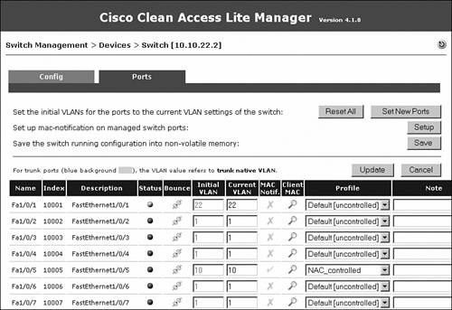
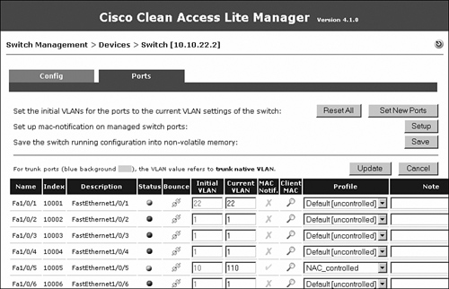
If you navigate to Switch Management > Device > Switches > List > 10.10.30.1 > Ports, you will see that interface Fa1/0/5 is not connected and is currently on VLAN 10 (Initial VLAN). This is shown in Figure 10-57.
Figure 10-57. Ports List—Before Connection
Now connect a laptop to interface Fa1/0/5. You will see that the port was immediately moved to the untrusted VLAN 110. This was triggered by the switch sending an SNMP MAC-notification trap to NAC Appliance Manager. The port was moved to VLAN 110 because the port profile had the auth (untrusted) VLAN set to VLAN 110. See Figure 10-58 for details.
Figure 10-58. Ports List—After Connection

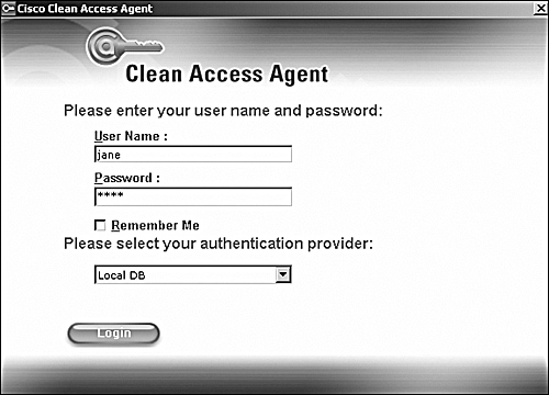
On the user PC, you will see that NAC Appliance Agent has popped up. Put in the credentials for the user jane, as shown in Figure 10-59.
Figure 10-59. Clean Access Agent Authentication Popup
When you click Login, NAC Appliance determines that the user jane belongs to the Employee user role. NAC Appliance looks at the OOB user role VLAN configured under the Employee user role and moves the user's switch port, Fa1/0/5, to VLAN 12. This is shown in Figure 10-60.
Figure 10-60. Ports List—After Authentication

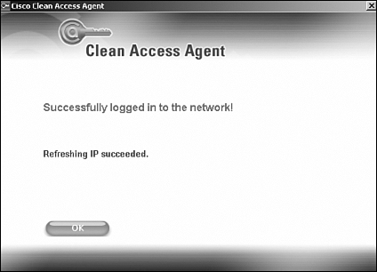
Because you changed the VLAN of the user from VLAN 110 to VLAN 12 in this process, you will also trigger a DHCP release/renew on the user's machine. As a result, during the login process, you will see the NAC Appliance agent screens shown in Figure 10-61 and Figure 10-62.
Figure 10-61. Agent Refreshing IP

Figure 10-62. Agent Refreshing IP Successful
The user appears in the OOB online user list, as shown in Figure 10-63. If the user is put in the Temporary role for remediation, it shows up in the in-band users list until it becomes clean.
Figure 10-63. Online Users List—OOB

Now if the user disconnects from the switch port, NAC Appliance removes the user from the online users list. This is triggered by the switch sending an SNMP linkdown trap to NAC Appliance Manager. The port VLAN, however, is not changed—it remains in VLAN 12.
Now another user, John, connects to the same switch port. The switch sends a new SNMP MAC-notification trap to NAC Appliance Manager. The port will immediately move to the auth (untrusted) VLAN 110, as shown in Figure 10-64, so that the new user can log in.
Figure 10-64. Ports List—Next User
On the user's machine, Clean Access Agent pops up, as shown in Figure 10-65. Put in the credentials for the user John and click Login.
Figure 10-65. Clean Access Agent Authentication Popup

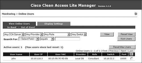
After the user is authenticated, NAC Appliance Manager determines that this user is a consultant and moves the user to VLAN 11, which is the VLAN configured for the OOB user role VLAN for the Guest role. The user shows up in the out-of-band online user list as a Consultant, as shown in Figure 10-66.
Figure 10-66. Online Users List—OOB
Additional Out-of-Band Considerations
Here is a list of other considerations worth noting in regard to the sample setup you just ran through:
- The previous steps covered a scenario in which users have NAC Appliance Agent and the agent is able to discover NAC Appliance Server.
Users who don't have NAC Appliance Agent have to be given a URL to which they can go for authentication. That URL should resolve to the untrusted port IP of NAC Appliance Server. Therefore, guest users who want to get network access can be given a URL, for example: http://hotspot.cisco.com/. You can put an entry into the DNS server to make this DNS name resolve to 10.10.21.5, which is the untrusted port IP of the NAS. - If you want to perform NAC Appliance Server load balancing in a Layer 3 OOB environment, you have several choices:
— Use a server load-balancing device, such as a Cisco ACE module.
— Use a discovery host IP address that points to a client that is reachable only by going through the servers. Then configure the network to load balance this address via routing.
— Use DNS round-robin to load balance the servers. Be careful with this method because it might not deal well with failures, depending on your environment. To use it, you can configure the DNS host name to resolve to the different servers and make the DNS server load balance between them. If you are using NAC Appliance Agent, you can configure the discovery host to be a DNS name instead of an IP, make the DNS server resolve that DNS name to the different servers, and load balance between them.
- In Out-of-Band mode, use SNMP traps to trigger the NAC process and SNMP sets to change the VLAN on the switch port. If configuring out-of-band in a Layer 3 environment, you must ensure that the network is reliable and will not drop the SNMP packets. You should consider this factor if you deploy Layer 3 OOB for remote sites where the SNMP traffic might traverse an unreliable or congested WAN link. You might consider prioritizing SNMP traffic on the WAN link using QoS mechanisms. Doing so will help ensure good SNMP communication between the switches at the remote site and NAC Appliance Manager at the central site. A future release of NAC Appliance will use SNMP informs to help with this issue.
Summary
In this chapter, you examined how to configure NAC Appliance using the Out-of Band deployment mode. You covered several of the design considerations for OOB as well as how it works. Two detailed, step-by-step OOB sample setups were given. The first setup used OOB with Layer 2 client adjacency, whereas the second setup used OOB with Layer 3 client adjacency. Each example provided instructions on how to configure each of the relevant devices in the solution. This includes the Cisco switches, routers, NAC Appliance Manager and NAC Appliance Server, and VLAN access lists where appropriate. These sample configurations are intended as guides to help you build your own NAC Appliance OOB solution that fits your environment.