
Chapter 6. Implement workload-specific security
Windows Server 2016 has a variety of features that can help administrators create working environments that are protected against attacks. Nano Server is a new Windows Server installation option that creates an operating system with a tiny resource footprint that greatly reduces the possible attack vectors. Containers are virtual instances of the operating system that provide software developers with a clean installation environment in seconds. Dynamic Access Control (DAC) is an Active Directory-based methodology for automatically assigning permissions to users, based on their roles in the organization.
Skills in this chapter:
![]() Secure application development and server workload infrastructure
Secure application development and server workload infrastructure
![]() Implement a secure file services infrastructure and Dynamic Access Control
Implement a secure file services infrastructure and Dynamic Access Control
Skill 6.1: Secure application development and server workload infrastructure
The Nano Server installation option and the two implementations of containers in Windows Server 2016 Windows Containers and Hyper-V Containers are intended to provide server and application environments that are more isolated and therefore more resistant to attack than standard Windows Server installations. Nano Server is isolated by its reduced overhead of processes, services, and open ports, and containers provide a separate operating system environment for an application that is unaffected by other services and applications running on the same physical computer.
![]() Determine usage scenarios, supported server workloads, and requirements for Nano Server deployments
Determine usage scenarios, supported server workloads, and requirements for Nano Server deployments
![]() Install and configure Nano Server
Install and configure Nano Server
![]() Implement security policies on Nano Servers using Desired State Configuration
Implement security policies on Nano Servers using Desired State Configuration
![]() Determine usage scenarios and requirements for Windows Server and Hyper-V containers
Determine usage scenarios and requirements for Windows Server and Hyper-V containers
![]() Install and configure Hyper-V containers
Install and configure Hyper-V containers
Determine usage scenarios, supported server workloads, and requirements for Nano Server deployments
In the Windows Server 2008 release, Microsoft introduced Server Core, a scaled-down installation option with reduced memory, storage, and maintenance requirements and a minimized attack surface. Server Core has no Windows Explorer shell, so the system is administered using the command and PowerShell prompts, and by remote management. In Windows Server 2016, Microsoft released Nano Server, another operating system installation option that is scaled down even further. Nano Server is headless; it has no local user interface, no 32-bit application support, and only the most basic configuration controls. There is no support for Remote Desktop; to administer the system, you use remote PowerShell, Windows Remote Management, and Windows Management Interface (WMI) tools.
Nano Server is designed to provide cloud-based infrastructure services with a minimal resource, management, and attack footprint. The two basic scenarios for Nano Server deployments are as follows:
![]() Server cloud infrastructure services, such as Hyper-V, Failover Clustering, Scale-Out File Servers, DNS, and Internet Information Services (IIS)
Server cloud infrastructure services, such as Hyper-V, Failover Clustering, Scale-Out File Servers, DNS, and Internet Information Services (IIS)
![]() Born-in-the-cloud applications running on virtual machines, containers, or physical servers, using development platforms that do not require a graphical interface
Born-in-the-cloud applications running on virtual machines, containers, or physical servers, using development platforms that do not require a graphical interface
Nano Server’s extremely small footprint enables the server to boot dramatically faster than Windows Server or Server Core, requires fewer updates, and provides a much smaller attack surface. By default, Nano Server runs less than half as many services and processes as a full Windows Server installation, and far fewer than Server Core, as well as maintaining fewer open ports.
Microsoft’s commitment to cloud-based services—whether public, private, or hybrid—has led to the need for highly-efficient servers dedicated to specific tasks. One of the largest obstacles in this pursuit was the relatively large size of the Windows Server resource footprint, even in Server Core. Nano Server is designed to provide a more efficient virtual machine-based infrastructure with lower memory and storage requirements, minimal downtime, and simplified maintenance.
When running as a Hyper-V virtual machine, Nano Server is remarkably efficient. By empirical standards, a Nano Server VM uses much less than half the assigned memory of a lightly loaded member server running the full Windows Server Desktop Experience, and less than a Server Core system as well. For demonstration purposes, Microsoft was able to run over 3,400 128 MB VMs on a single computer with eight 20-core processors and 1 terabyte of RAM.
The headless nature of the Nano Server design does not mean that administrators are limited to PowerShell and Command Prompt management tools, although these are certainly available. You can connect to a Nano Server remotely using the standard Windows graphical tools, if desired, including Hyper-V Manager and other Microsoft Management Console (MMC) snap-ins, Server Manager, and even System Center.
The main shortcoming of the Nano Server design, at least at this point in its development, is its relatively limited utility. The server supports only a small subset of the roles and features in the full Windows Server product. However, the roles that are supported in Nano Server are particularly well-suited to cloud deployments. You can run IIS web servers, file servers, and Hyper-V servers, and, with the clustering and container support provided, these services are both resilient and highly scalable.
Install and configure Nano Server
There is no wizard for installing Nano Server, as there is for Windows Server and Server Core. You install the operating system by creating a Virtual Hard Disk (VHD) on another computer, from the PowerShell command line. Then you use the VHD to create a Hyper-V virtual machine or a boot drive for a physical server.
Windows Server 2016 includes a Nano Server directory on its installation disk or image file, which contains the Nano Server image, a PowerShell module, and a subdirectory containing the package files for the roles and features the operating system supports. Importing the PowerShell module provides the cmdlets you use to create and edit Nano Server images. The package files contain specially-created versions of the roles and features you can install directly to the VHD file. Despite their similarity to the versions used by Windows Server and Server Core, the roles are not interchangeable. You cannot install roles from the full Windows Server product on a Nano Server system.
Creating a Nano Server image
To create a new Nano Server image, open a PowerShell session with administrative privileges on a computer with the Windows Server 2016 installation media loaded or mounted. Then, switch to the NanoServer folder on the installation disk and import the Windows PowerShell module required to provide the cmdlets for Nano Server, using the following command:
Import-Module .NanoServerImageGenerator -Verbose
Importing the module provides you with access to the New-NanoServerImage cmdlet, which you use to create a Nano Server VHD file.
To run the New-NanoServerImage cmdlet, use the following basic syntax:
new-nanoserverimage -deploymenttype guest|host -edition standard|datacenter -mediapath
root -targetpath pathfilename -computername name
The required parameters for the New-NanoServerImage cmdlet are as follows:
![]() DeploymentType Specifies whether the image file is used on a Hyper-V virtual machine (Guest) or a physical server (Host).
DeploymentType Specifies whether the image file is used on a Hyper-V virtual machine (Guest) or a physical server (Host).
![]() Edition Specifies whether to install the Standard or Datacenter edition of Nano Server.
Edition Specifies whether to install the Standard or Datacenter edition of Nano Server.
![]() MediaPath Specifies the path to the root of the Windows Server 2016 installation disk. or mounted image.
MediaPath Specifies the path to the root of the Windows Server 2016 installation disk. or mounted image.
![]() BasePath Specifies a path on the local system where the cmdlet creates a copy of the installation files from the location specified in the -MediaPath parameter. Once the copy is created, you can use the BasePath parameter only for future NewNanoServerImage commands and omit the MediaPath parameter. This parameter is optional.
BasePath Specifies a path on the local system where the cmdlet creates a copy of the installation files from the location specified in the -MediaPath parameter. Once the copy is created, you can use the BasePath parameter only for future NewNanoServerImage commands and omit the MediaPath parameter. This parameter is optional.
![]() TargetPath Species the full path and filename of the new image to be created. The filename extension (.vhd or .vhdx) specifies whether the new image should be Generation 1 or Generation 2.
TargetPath Species the full path and filename of the new image to be created. The filename extension (.vhd or .vhdx) specifies whether the new image should be Generation 1 or Generation 2.
![]() ComputerName Specifies the computer name that should be assigned to the new image.
ComputerName Specifies the computer name that should be assigned to the new image.
An example of the command to create a standard, Generation 2 Nano Server image with the computer name Nano1, for use on a virtual machine, would be as follows:
new-nanoserverimage -deploymenttype guest -edition standard -mediapath d: -targetpath
c: emp
anoserver1.vhdx -computername nano1
As the command runs, it prompts you for a password that is applied to the Administrator account in the Nano Server image. The output generated by the cmdlet appears as shown in Figure 6-1.

After the cmdlet creates the VHD file, it adds any packages you specified in the command. For example, the Guest drivers specified by the DeploymentType parameter are provided as a package, which the cmdlet installs to the VHD file. To install additional packages provided with Nano Server, you can add optional parameters to the NewNanoServerImage command line.
The optional parameters for the NewNanoServerImage cmdlet are as follows:
![]() Compute Installs the Hyper-V role on the image specified by the TargetPath variable.
Compute Installs the Hyper-V role on the image specified by the TargetPath variable.
![]() Clustering Installs the Failover Clustering role on the image specified by the TargetPath variable.
Clustering Installs the Failover Clustering role on the image specified by the TargetPath variable.
![]() OEMDrivers Add the basic drivers included in Server Core to the image specified by the TargetPath variable.
OEMDrivers Add the basic drivers included in Server Core to the image specified by the TargetPath variable.
![]() Storage Installs the File Server role and other storage components on the image specified by the TargetPath variable.
Storage Installs the File Server role and other storage components on the image specified by the TargetPath variable.
![]() Defender Installs Windows Defender on the image specified by the TargetPath variable.
Defender Installs Windows Defender on the image specified by the TargetPath variable.
![]() Containers Installs host support for Windows Containers on the image specified by the TargetPath variable.
Containers Installs host support for Windows Containers on the image specified by the TargetPath variable.
![]() Packages Installs one or more Nano Center packages from among the following:
Packages Installs one or more Nano Center packages from among the following:
![]() MicrosoftNanoServerDSCPackage Installs the Desired State Configuration (DSC) package on the image specified by the TargetPath variable.
MicrosoftNanoServerDSCPackage Installs the Desired State Configuration (DSC) package on the image specified by the TargetPath variable.
![]() MicrosoftNanoServerDNSPackage Installs the DNS Server role on the image specified by the TargetPath variable.
MicrosoftNanoServerDNSPackage Installs the DNS Server role on the image specified by the TargetPath variable.
![]() Microsoft-NanoServer-IIS-Package Installs the IIS role on the image specified by the TargetPath variable.
Microsoft-NanoServer-IIS-Package Installs the IIS role on the image specified by the TargetPath variable.
![]() Microsoft-NanoServer-SCVMM-Package Installs the System Center Virtual Machine Manager agent on the image specified by the TargetPath variable.
Microsoft-NanoServer-SCVMM-Package Installs the System Center Virtual Machine Manager agent on the image specified by the TargetPath variable.
![]() Microsoft-NanoServer-SCVMM-Compute-Package Installs the Hyper-V role on the image specified by the TargetPath variable, so that is it manageable with System Center Virtual Machine Manager. Do not use with the Compute parameter.
Microsoft-NanoServer-SCVMM-Compute-Package Installs the Hyper-V role on the image specified by the TargetPath variable, so that is it manageable with System Center Virtual Machine Manager. Do not use with the Compute parameter.
![]() Microsoft-NanoServer-NPDS-Package Installs the Network Performance Diagnostics Service on the image specified by the TargetPath variable.
Microsoft-NanoServer-NPDS-Package Installs the Network Performance Diagnostics Service on the image specified by the TargetPath variable.
![]() Microsoft-NanoServer-DCB-Package Installs Data Center Bridging on the image specified by the TargetPath variable.
Microsoft-NanoServer-DCB-Package Installs Data Center Bridging on the image specified by the TargetPath variable.
![]() Microsoft-NanoServer-SecureStartup-Package Installs Secure Startup on the image specified by the TargetPath variable.
Microsoft-NanoServer-SecureStartup-Package Installs Secure Startup on the image specified by the TargetPath variable.
![]() Microsoft-NanoServer-ShieldedVM-Package Installs the Shielded Virtual Machine package on the image specified by the TargetPath variable (Datacenter edition only).
Microsoft-NanoServer-ShieldedVM-Package Installs the Shielded Virtual Machine package on the image specified by the TargetPath variable (Datacenter edition only).
Joining a Domain
To create a new Nano Server image that is a member of a domain, you are essentially performing an offline domain join. To do this, you must have access to the domain the Nano Server joins so that you can harvest a domain provisioning file (called a blob) and apply it to the newly created VHD file.
The NewNanoServerImage cmdlet supports a DomainName parameter, which you can use when you are creating the image on a computer that is a member of the domain, and you are logged on using an account that has the privileges needed to create domain computer accounts. You specify the DomainName parameter on the NewNanoServerImage command line with the name of the domain the new image joins, as in the following example:
new-nanoserverimage -deploymenttype guest -edition standard -mediapath d: -targetpath
c: emp
anoserver2.vhdx -computername nano2 -domainname contoso
Once the command processing completes and the new image is created, a new Computer object appears in Active Directory, as shown in Figure 6-2.

Note Reusing A Domain Computer Name
If a computer account with the name specified in the ComputerName parameter already exists in Active Directory, you can configure a Nano Server image to reuse that account by adding the ReuseDomainNode parameter to the NewNanoServerImage command line.
It is possible to join a new Nano Server image to a domain when creating it on a computer that is not a domain member, but the process is more complicated. In this case, you have to harvest the blob file on a domain member computer, and then copy it to the computer where you intend to run New-NanoServerImage.
You create a blob file with the Djoin.exe tool included with Windows Server 2016, using the following syntax:
djoin /provision /domain domainname /machine computername /savefile filename.txt
An example of a Djoin provisioning command would be as follows:
djoin /provision /domain contoso /machine nano3 /savefile nano3blob.txt
Provisioning the computer in this way creates the computer account in the domain and creates a text file using the name you specified in the Djoin command. Although the blob is a text file, the information it contains is encoded, as shown in Figure 6-3.

After you copy the blob file to the computer where you create the new Nano Server image, you run the NewNanoServerImage cmdlet with the DomainBlobPath parameter, specifying the location of the blob file, as in the following example:
new-nanoserverimage -deploymenttype guest -edition standard -mediapath d: -targetpath
c: emp
anoserver2.vhdx -computername nano2 -domainblobpath c: emp
ano3blob.txt
Creating a Nano Server VM
Once you have created a Nano Server VHD or VHDX image file, using the NewNanoServerImage cmdlet, you can proceed to deploy it. In the case of a virtual machine (for which you specified Guest in the DeploymentType parameter), you create a new VM in Hyper-V, using the Nano Server VHD or VHDX image file instead of creating a new one.
If you create the VM using the New Virtual Machine Wizard in Hyper-V Manager, you select the Use an Existing Virtual Hard Disk option on the Connect Virtual Hard Disk page, and select the Nano Server image file you created, as shown in Figure 6-4.

If you use the New-VM PowerShell cmdlet to create the virtual machine, you use the VHDPath parameter to specify the name and location of the Nano Server image file, as in the following example:
new-vm -name "Nano2" -generation 2 -memorystartupbytes 1GB -vhdpath "f:hyper-vvirtual
hard disks
ano2.vhdx"
Note Creating the Correct Generation VM
As mentioned earlier, the file extension you supply in the TargetPath parameter specifies whether the NewNanoServerImage cmdlet creates a Generation 1 or Generation 2 image. When creating the new virtual machine in Hyper-V, be sure to specify a Generation 1 VM for a VHD file or a Generation 2 VM for a VHDX file.
Logging on to a Nano Server
Once you have deployed the VHD image in a virtual machine and started the Nano Server system, a simple, character-based authentication screen appears, as shown in Figure 6-6.

After you log on, the Nano Server Recovery Console screen appears, as shown in Figure 6-6. This screen provides only the minimal controls you might need to configure the system’s remote administration client capabilities.

You can configure the network interfaces, set Windows Firewall rules, and configure Windows remote Management (WinRM). Once the system is ready to listen for calls from remote management tools, there is nothing more to do from the Nano Server console. All subsequent administration occurs remotely.
Configuring a Nano Server IP address
As with the other Windows Server installation options, Nano Server has its Dynamic Host Configuration Protocol (DHCP) client enabled by default. If you have a DHCP server on your network, Nano Server obtains an IP address from it and configure the system’s network adapter. If no DHCP server is available, you can configure the network adapter manually, using parameters in the NewNanoServerImage command line, or using one of the few functions available in the Nano Server Recovery Console.
You can configure a network adapter in a Nano Server as you create the VHD image file, by specifying the IP configuration settings on the NewNanoServerImage command line. The parameters to use are as follows:
![]() InterfaceNameOrIndex Identifies the network adapter in the Nano Server to which the settings in the following parameters should be applied. In a machine with a single network interface adapter, the value Ethernet should be sufficient.
InterfaceNameOrIndex Identifies the network adapter in the Nano Server to which the settings in the following parameters should be applied. In a machine with a single network interface adapter, the value Ethernet should be sufficient.
![]() Ipv4Address Specifies the IPv4 address to be assigned to the network adapter identified by the InterfaceNameOrIndex parameter.
Ipv4Address Specifies the IPv4 address to be assigned to the network adapter identified by the InterfaceNameOrIndex parameter.
![]() Ipv4SubnetMask Specifies the Subnet Mask value associated with the IP address specified in the Ipv4Address parameter.
Ipv4SubnetMask Specifies the Subnet Mask value associated with the IP address specified in the Ipv4Address parameter.
![]() Ipv4Gateway Specifies the IP address of a router on the local network where the IP address specified in the Ipv4Address parameter is located, that provides access to other networks.
Ipv4Gateway Specifies the IP address of a router on the local network where the IP address specified in the Ipv4Address parameter is located, that provides access to other networks.
![]() Ipv4Dns Specifies the IP address of the DNS server that the system should use to locate resources.
Ipv4Dns Specifies the IP address of the DNS server that the system should use to locate resources.
An example of the NewNanoServerImage command line including these parameters would be as follows:
new-nanoserverimage -deploymenttype guest -edition standard -mediapath d: -targetpath c: emp
anoserver4.vhdx -computername nano4 -domain contoso.com -interfacenameorindex ethernet -ipv4address 192.168.10.41 -ipv4subnetmask 255.255.255.0 -ipv4gateway
192.168.10.1 -ipv4dns 192.168.10.2
To manually configure the network adapter to use a static IP address from the Nano Server Recovery Console, after the image has been created and deployed, use the following procedure:
1. Select the Networking item and press Enter.
Note Using the Nano Server Recovery Console Interface
The Nano Server Recovery Console has no support for the mouse, and even its keyboard support is limited. Number pads are not supported, nor are CapsLk and NumLk keys. To navigate the interface, you use the cursor keys or the Tab key to highlight an option and press Enter to select it. The legend at the bottom of the screen specifies additional key combinations.
2. On the Network Settings screen, select a network adapter and press Enter.
3. On the Network Adapter Settings screen, shown in Figure 6-7, press F11 to configure the IPv4 settings for the adapter.

4. On the IP Configuration screen, press F4 to toggle the DHCP client to Disabled, as shown in Figure 6-8.

5. Press the Tab key to advance to the IP Address field and type an IP address for the adapter.
6. Press the Tab key to advance to the Subnet Mask field and type the mask associated with the IP address.
7. Press the Tab key to advance to the Default Gateway field and type the address of a router on the network.
8. Press Enter to save your settings.
9. Press Enter again to confirm the Save.
10. Press Esc to return to the Network Adapter Settings screen.
11. Press F12 to configure IPv6 Settings or F10 to modify the routing table, if necessary.
12. Press Esc twice to return to the Nano Server Recovery Console.
Note Configuring A DNS Server Address
Unusually, there is no way to specify a DNS server address in the Nano Server Recovery Console interface. To configure the DNS server address for an initial Nano Server configuration, you must use the Ipv4Dns parameter on the NewNanoServerImage command line or use DHCP to supply the address.
Configuring Firewall rules
Depending on what remote tools you intend to use to manage Nano Server, you might have to work with Windows Firewall rules to provide appropriate access to the computer. The local interface on Nano Server enables you to enable or disable existing firewall rules, both inbound and outbound, to open and close ports as needed.
On the Nano Server Recovery Console screen, when you select Inbound Firewall Rules or Outbound Firewall Rules, you see a scrollable screen containing all of the default rules on the system, as shown in Figure 6-9.

Selecting a rule displays a Firewall Rule Details screen containing information about the rule, including the port affected by the rule and whether it is currently enabled, as shown in Figure 6-10. You can then press the F4 key to enable or disable the rule.

This interface does not provide full administrative access to Windows Firewall. It is intended only to provide you with sufficient control to gain remote access to the Nano Server. You can activate or deactivate an existing rule, but you cannot modify rules themselves or create new ones. Once you have remote access to the Nano Server, you can use standard tools, such as the Windows Firewall with Advanced Security console or the Windows PowerShell cmdlets, to exercise complete control over the firewall.
Configuring Windows Remote Management
The WinRM entry on the Nano Server Recovery Console screen provides only a single function, the ability to reset the WinRM service and firewall to their default settings, in the event that the Nano Server’s configuration is preventing you from establishing a connection with a remote management tool.
Connecting to a Nano Server using PowerShell
In most cases, a newly-installed Nano Server with a proper network adapter configuration should be ready to listen for incoming connection requests from remote management tools. For example, to connect to a Nano Server using Windows PowerShell, you create a PowerShell session using the NewPSSession cmdlet, using following basic syntax:
new-pssession -computername name -credential domainusername
The values you use for the ComputerName and Credential parameters in this command depend on whether the Nano Server is already a member of a domain. For a domain-joined Nano Server, you should be able to connect by specifying the fully-qualified domain name of the Nano Server and a domain account name, as in the following example:
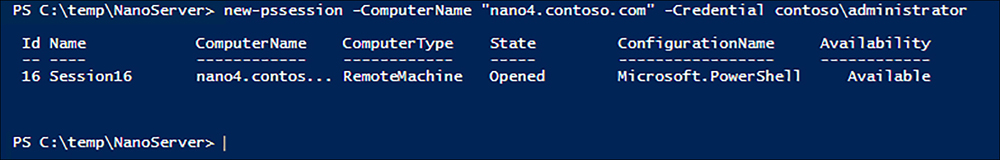
new-pssession -computername nano4.contoso.com -credential contosoadministrator
The cmdlet prompts for a password for the administrator account and creates a new session, as shown in Figure 6-11. The output from the cmdlet specified the ID for the session, which you use to connect to it.
When the Nano Server is not joined to a domain, the process of creating a new session can be more complicated. First, you must consider whether or not the computer name of the Nano Server can be resolved. If the network adapter has been configured by DHCP, you can probably use the computer’s name in the ComputerName parameter, as in the following example:
new-pssession -computername nano4 -credential -administrator
Omitting the domain name from the Credential parameter causes the cmdlet to prompt you for the local account password.
If you have manually configured the network adapter, you might have to use the Nano Server’s IP address instead of its computer name, as in the following example:
new-pssession -computername 192.168.10.41 -credential -administrator
Second, you have to add the Nano Server to the computer’s Trusted Hosts list in the Windows Remote Management implementation. Otherwise, the cmdlet tries to use Kerberos to authenticate the session, which fail in the case of a non-domain-joined host.
To add a computer to the Trusted Hosts list using PowerShell, you specify its name or IP address in the Set-Item cmdlet, as in the following example:
set-item wsman:localhostclient rustedhosts "192.168.10.41"
You can also use the Winrm.exe tool from the command prompt, as follows:
winrm set winrm/config/client @{TrustedHosts="192.168.10.41"}
Once you have successfully created a PowerShell session, you can connect to it using the EnterPSSession cmdlet, specifying the ID displayed in the New-PSSession output, as in the following example:
enter-pssession -id 16
When you successfully connect to the session, the command prompt changes to include the remote computer name, as shown in Figure 6-12.

Once you have connected to the session, you are working with the Nano Server’s PowerShell resources. The Windows PowerShell 5.1 version included in Windows Server 2016 now exists in two editions: Desktop and Core. The full version of Windows Server 2016 and Server Core both include the Desktop edition. Nano Server includes the PowerShell Core edition, as displayed in the $PSVersionTable variable, shown in Figure 6-13.

PowerShell Core is a subset of PowerShell Desktop, omitting many of its features. Administrators and developers with existing PowerShell code should test it on a PowerShell Core implementation.
Need More Review? Powershell Core Feature Omissions
For a list of the features not included in PowerShell Core, see https://technet.microsoft.com/en-us/windows-server-docs/compute/nano-server/powershell-on-nano-server.
To disconnect from a connected session, you can use the ExitPSSession cmdlet, or just type Exit. The command prompt returns to its original form, and you are back working with the host computer.
Implement security policies on Nano Servers using Desired State Configuration
As discussed earlier, remote management is an essential part of maintaining Nano Server installations, and it is possible for administrators to use most of their familiar tools—graphical and textual—to connect to a Nano Server and access its functions. However, Nano Server is particularly well-suited to high-density installations. Microsoft has created test deployments with thousands of Nano Server virtual machines running on a single Hyper-V host. In an environment like this, administering each VM individually would be an enormous task. One possible solution is to use the Windows PowerShell Desired State Configuration (DSC) feature to deploy standardized configurations to multiple Nano Servers.
As mentioned in Chapter 4, “Manage Privileged Identities,” Desired State Configuration (DSC) is a Windows PowerShell feature that uses script files to apply, monitor, and maintain a specific system configuration. DSC consists of three components, as follows:
![]() Configurations PowerShell scripts that contain node blocks specifying the names of the computers to be configured and resource blocks specifying the property settings to be applied
Configurations PowerShell scripts that contain node blocks specifying the names of the computers to be configured and resource blocks specifying the property settings to be applied
![]() Resources The individual building blocks that specify settings or components and the values that the configuration should assign to them
Resources The individual building blocks that specify settings or components and the values that the configuration should assign to them
![]() Local Configuration Manager (LCM) The engine running on the local system that receives configurations and applies them to the computer
Local Configuration Manager (LCM) The engine running on the local system that receives configurations and applies them to the computer
To use DSC, administrators create configuration script files containing resource blocks, compile them into modules, and deploy them on a central file or web server. The LCM then receives the configuration modules from the server, using a push or pull relationship, and applies them to the system. The LCM also maintains the system configuration by monitoring the system, ensuring that the required resource settings are maintained and reapplying them if necessary. DSC configurations are idempotent, meaning that the scripts can be applied to a system repeatedly without generating errors or other undesirable results.
The Nano Server product in Windows Server 2016 includes a DSC package that you can install from the New-NanoServerImage command line by adding the Packages Microsoft-NanoServer-DSC-Package parameter. As with most of Nano Server’s components, the DSC implementation is a subset of the full featured one in Windows Server 2016.
For example, you can configure a Nano Server to pull configurations from a DSC server, or receive configurations pushed from a server, but a Nano Server cannot function as a pull server for other clients. The Nano Server DSC implementation does include all of the cmdlets from the full version.
Need More Review? Nano Server DSC Capabilities
For a complete list of what the Nano Server Desired State Configuration feature can and cannot do, see https://msdn.microsoft.com/en-us/powershell/dsc/nanodsc.
Creating DSC Configuration Scripts
A simple DSC configuration script to configure the DNS server address might appear as shown in Listing 6-1.
LISTING 6-1 Sample DSC Configuration Script
Configuration DnsClient
{
Import-DscResource -ModuleName "xNetworking"
Node ("ServerA","ServerB")
{
xDnsServerAddress DnsServer
{
Address = 10.0.0.1
AddressFamily = "Ipv4"
InterfaceAlias = "Ethernet"
}
}
}
In this script, the configuration, called DnsClient, ensures that the two computers, ServerA and ServerB, have their DNS Server Address setting configured. The Import-DscModule command loads a module called xNetworking. The Node block specifies the names of the computers. The xDnsServerAddress statement specifies the resource in the module to be configured, and Address, containing the DNS server address, is the property for that resource. When the configuration is applied to a client, its LCM checks to see if the Ipv4 DNS Server Address for the specified network adapter is configured correctly. If it is, then nothing happens. If it is not, then the LCM configures it.
This particular script is appropriate for a Nano Server, because of the issues with DNS server configuration discussed earlier in this chapter. However, this is only the basic model for a configuration. Configuration scripts are often vastly more complicated than this. To configure security settings on a Nano Server, you can create a configuration that specifies registry key values to be applied, or that uses any of the hundreds of DSC resources available in modules downloadable from Microsoft’s PowerShell Gallery (at http://powershellgallery.com). The xNetworking module used in the sample script is available there.
Compiling DSC configurations
When you run the configuration script, PowerShell creates a Management Object Format (MOF) file for each computer specified in the Node block. The output created by running the sample script shown earlier appears in Figure 6-14.

The MOF files are the actual scripts that are distributed to the DSC clients.
Deploying DSC configurations
To deploy a DSC configuration module, the administrator must decide between implementing a pull or a push architecture. In a pull architecture, the MOF files are stored on a Pull Server, which is an SMB server or an IIS web server with an OData interface, set up with its own DSC configuration.
Once you have published the MOF files on the Pull Server, you must configure the LCM on the client computers with a local configuration script that provides the URL of the Pull Server and creates a scheduled task. When both the DSC server and the client are properly configured, the LCM on the client periodically checks the Pull Server for configurations and examines the local system for compliance. When necessary, the LCM downloads configuration files from the Pull Server and applies them to the local system.
In a push architecture, the administrator runs the Start-DscConfiguration cmdlet on the server, specifying the location where the MOF files are stored in the -Path parameter. By default, the cmdlet pushes the specified configuration to all of the clients that have MOF files in the specified path. However, you can also select individual computers for deployment, using the -ComputerName parameter, as in the following example:
start-dscconfiguration -path cdscdnsclient -computername servera -credential contosoadministrator -wait -verbose
Determine usage scenarios and requirements for Windows Server and Hyper-V containers
Hyper-V enables you to create virtual machines with processor, memory, and storage resources that appear to be isolated from the host computer and from other virtual machines. Windows Server installation options, such as Server Core and Nano Server, are designed to make these virtual machines smaller and more efficient. Containers are another form of virtualization, which provide multiple, isolated instances of the operating system on a single physical computer.
Like virtual machines, containers provide what appear to be separate instances of the operating system, each with its own processor, memory, and storage resources. Unlike virtual machines, however, which run completely separate copies of the operating system, containers actually share the operating system of the host system. There is no need to install a separate instance of the operating system for each container, nor does the container have to perform a boot sequence, load libraries, or devote memory to the operating system files. Containers start in seconds, and you can create more containers on a host system than you can virtual machines.
To users working in containers, what they appear to see is a clean operating system installation, ready for applications. The environment is completely separated from the host, and from other containers, using namespace isolation and resource governance.
Namespace isolation means that each container only has access to the resources that are available to it. Files, ports, and running processes all appear to be dedicated to the container, even when they are being shared with the host and with other containers. The working environment appears similar to that of a virtual machine, but unlike a virtual machine, which maintains separate copies of all of the operating system files, a container is actually sharing these files with the host, not copying them. It is only when a user or application in a container modifies a file that a copy is made in the container’s file system.
Resource governance means that a container has access only to a specified amount of processor cycles, system memory, network bandwidth, and other resources, and no more. An application running in a container has a clean sandbox environment, with no access to resources allocated to other containers or to the host.
The ability to create new containers in seconds, and the isolated nature of each container, make an ideal platform for application development and software testing.
Two flavors of containers
Windows Server 2016 supports two types of containers: Windows Server Containers and Hyper-V containers. The difference between the two is in the degree of container isolation they provide. Windows Server Containers share everything with the host computer, including the operating system kernel and the system memory.
Because of this, it is conceivable that an application, whether accidentally or deliberately, might be able to escape from the confines of its container and affect other processes running on the host or in other containers. This option is therefore presumed to be preferable when the applications running in different containers are basically trustworthy.
Hyper-V provide an additional level of isolation by using the hypervisor to create a separate copy of the operating system kernel for each container. The containers also have their own memory assigned to them and isolated storage and network I/O. This provides a container environment that is suitable for what Microsoft calls “hostile multi-tenant” applications, such as a case in which a business provides containers to clients for running their own code, which might not be trustworthy. Thus, with the addition of Hyper-V containers, Windows Server 2016 provides three levels of isolation, ranging from the separate operating system installation of Hyper-V virtual machines, to the separate kernel and memory of Hyper-V containers, to the shares kernel and other resources of Windows Server Containers.
Windows Server 2016 and Docker
Windows Server 2016 includes a Containers, which you must install before you can create either type of container in Windows. However, the tool you use to create and manage containers is a third-party product called Docker. Docker consists of APIs, a Windows service, and a client program, which enable you to create containers out of existing image files.
Docker is an application that was originally created for the creation and management of containers on Linux systems. Now ported to Windows, you use Docker to create and manage both Windows Server Containers and Hyper-V containers. In fact, the two types of containers are interchangeable. You can create an image for a Windows Server Container and later run it in a Hyper-V container without modification.
Note Container Portability
While Windows-based containers are interchangeable between Windows Server Containers and Hyper-V containers, Windows containers are not interchangeable with Linux containers. You cannot run a Linux container in Windows, nor can you run a Windows container on a Linux machine. This is because the kernel APIs of the two operating systems are not compatible.
Install and configure Hyper-V containers
To install support for containers in Windows Server 2016, you must first add the Containers feature, either by running the Add Roles and Features Wizard in Server Manager, or by using the Install-WindowsFeature cmdlet in a Windows PowerShell session with administrative privileges, as follows:
install-windowsfeature -name containers -restart
The Containers feature provides operating system support for both Windows Server Containers and Hyper-V containers, but it does not include the Docker application. You must download and install this yourself.
Docker consists of two files, as follows:
![]() Dockerd.exe The Docker service, which runs in the background on the Windows computer
Dockerd.exe The Docker service, which runs in the background on the Windows computer
![]() Docker.exe The Docker client, a command line tool that you use to create and manage containers
Docker.exe The Docker client, a command line tool that you use to create and manage containers
There is no automatic installer for these files. You must create a folder on your computer called C:Program FilesDocker and use the following two Invoke-WebRequest commands in PowerShell to download them.
invoke-webrequest -uri https://aka.ms/tp5/b/dockerd -outfile "c:program filesdocker
dockerd.exe"
invoke-webrequest -uri https://aka.ms/tp5/b/docker -outfile "c:program filesdocker
docker.exe"
With the Docker program files in place, you can then register the Dockerd program as a service by performing the following command from a Command Prompt with administrative privileges:
dockerd --register-service
Note Performing Docker Commands
Note that this, and other, Docker commands sometimes use double hyphens to proceed command line parameters.
Finally, start the docker service using the PowerShell Start-Service cmdlet, as follows:
start-service -name docker -force
With the docker service running, you can now use the docker client to download the images needed to create a new container. For example, the following command downloads the latest Nano Server container image from the Docker repository.
docker pull microsoft/windowsservercore
Once the download is complete, it is time to create a new container from the image. The following docker command creates a new Windows Server Container from the Nano Server image
docker run -it microsoft/windowsservercore cmd
This command creates a container from the windowsservercore image you downloaded and executes the cmd command in the container, opening a command prompt window. If you examine the files displayed by the dir command, you can see that you are interacting with a clean OS installation inside the container, not the host computer.
Type exit to return to the PowerShell session on the host computer, and you can use the following command to display the containers running on the system, as shown in Figure 6-15.
docker ps

To create a Hyper-V container, you must have the Hyper-V role installed on the host computer. Then, you execute the same command, with the addition of the isolation parameter, as in the following example:
docker run -it --isolation=hyperv microsoft/windowsservercore cmd
Once you have created a container, you can use the following Docker commands to manage it. The commands typically take the form of a keyword, followed by the container ID, and then any other necessary parameters. To display the help screen for a command, run the command with the help parameter.
![]() Docker stop Stops a running container
Docker stop Stops a running container
![]() Docker start Starts a stopped container
Docker start Starts a stopped container
![]() Docker restart Restarts a container
Docker restart Restarts a container
![]() Docker exec Executes a command in a running container
Docker exec Executes a command in a running container
![]() Docker commit Creates a new image from a modified container
Docker commit Creates a new image from a modified container
![]() Docker cp Copies files between the container operating system and the host operating system
Docker cp Copies files between the container operating system and the host operating system
Skill 6.2: Implement a Secure File Services infrastructure and Dynamic Access Control
File sharing is one of the primary functions of the data network. While Windows has provided file system security since its inception, in the form of permissions, it is only relatively recently that Windows has gone beyond that, to provide a more secure and more flexible file services infrastructure. File Server Resource Manager is a tool that administrators can use to apply storage quotas to users, screen files, and generate reports on storage use.
Dynamic Access Control (DAC) is a system by which administrators can assign permissions to users based on predefined sets of rules. For example, a user in a management role might be granted access to files that other users cannot. In addition, that same user might be able to access the files from an office computer, but not from a home computer. By creating rules of this type, you can build a self-sustaining system of permission assignments, to accommodate users as they change jobs and files as their security requirements change.
This section covers how to:
![]() Install the File Server Resource Manager role service
Install the File Server Resource Manager role service
![]() Configure file management tasks
Configure file management tasks
![]() Configure File Classification Infrastructure using FSRM
Configure File Classification Infrastructure using FSRM
![]() Configure user and device claim types
Configure user and device claim types
![]() Create and configure resource properties and lists
Create and configure resource properties and lists
![]() Create and configure Central Access rules and policies
Create and configure Central Access rules and policies
![]() Implement policy changes and staging
Implement policy changes and staging
![]() Configure file access auditing
Configure file access auditing
![]() Perform access-denied remediation
Perform access-denied remediation
Install the File Server Resource Manager role service
File Server Resource Manager (FSRM) is a Microsoft Management Console (MMC) snap-in that enables administrators to monitor and regulate the storage resources consumed by network users. Although the price of hard disk storage continues to decrease, network users still have a tendency to consume all of the storage space that administrators allocate to them. In addition, the increasingly common use of high definition audio and video files means that single files can be several gigabytes in size, adding to rapid disk space consumption.
In an enterprise environment, it is important for administrators to monitor and regulate the amount of storage space consumed by users, so that server resources are not overwhelmed by irresponsible user storage practices.
When you install the File Server Resource Manager role service in the File and Storage Services role, Windows Server 2016 installs a graphical tool that enables file server administrators to monitor and regulate their server storage, by performing the following tasks:
![]() Establish quotas that limit the amount of storage space allotted to each user
Establish quotas that limit the amount of storage space allotted to each user
![]() Create screens that prevent users from storing specific types of files on server drives
Create screens that prevent users from storing specific types of files on server drives
![]() Create templates that simplify the process of applying quotas and screens
Create templates that simplify the process of applying quotas and screens
![]() Automatically send notifications to users and/or administrators when quotas are exceeded or nearly exceeded
Automatically send notifications to users and/or administrators when quotas are exceeded or nearly exceeded
![]() Generate reports providing details of users’ storage activities
Generate reports providing details of users’ storage activities
To install File Server Resource Manager, you can use the Add Roles and Features Wizard in Server Manager. By default, Windows Server 2016 installs the File Server and Storage Services role services, which are part of the File and Storage Services role, as shown in Figure 6-16. File Server Resource Manager is another role service in that role, which you can add using the wizard by selecting the appropriate checkbox.

To install File Server Resource Manager using Windows PowerShell, you can open a PowerShell session with administrative privileges and run the Install-WindowsFeature cmdlet, specifying the role service using the -Name parameter, as in the following example:
install-windowsfeature -name fs-resource-manager
The resulting output of a successful installation is shown in Figure 6-17.

Note Displaying Powershell Feature Names
To display the PowerShell names for the Windows roles and features that are available for installation, run the Get-WindowsFeature cmdlet.
Configure quotas
Quotas, in File Server Resource Manager, are settings that can warn administrators of trends in excessive storage utilization, or they can apply hard restrictions on the storage available to user accounts. A quota is simply a limit on the storage space a user is permitted to consume in a particular volume or folder.
Quotas are based on file ownership. Windows automatically makes a user the owner of all files that he or she creates on a server volume. The quota system tracks all of the files owned by each user and calculates their total size. When the total size of a given user’s files reaches the quota specified by the server administrator, the system takes action, also specified by the administrator.
The actions the system can take when a user approaches or reaches a quota are highly configurable. For example, administrators can configure quotas to be hard or soft. A hard quota prohibits users from consuming any storage space beyond the allotted amount, while a soft quota allows the user additional storage space and just sends a notification to the user and/or administrator. Administrators can specify the thresholds at which the system should send notifications and configure the server to generate event log entries and reports in response to quota thresholds.
Creating quota templates
While it is possible to create a quota from scratch for each individual user, this is not a practical solution for an enterprise networks. Instead, FSRM enables you to create quota templates, to manage quota assignments on a large scale. A quota template is a collection of settings that defines the following:
![]() Whether a quota should be hard or soft
Whether a quota should be hard or soft
![]() What thresholds FSRM should apply to the quota
What thresholds FSRM should apply to the quota
![]() What actions FSRM should take when a user reaches a threshold
What actions FSRM should take when a user reaches a threshold
The File Server Resource Manager console includes several predefined templates, which you can use to create your own template. To create a quota template, use the following procedure.
1. Using an account with administrator privileges, open File Server Resource Manager from the Tools menu in Server Manager. The File Server Resource Manager console appears, as shown in Figure 6-18.

2. Expand the Quota Management node and select Quota Templates to display the predefined templates included with FSRM, as shown in Figure 6-19.

3. Right-click the Quota Templates node and, from the context menu, select Create Quota Template. The Create Quota Template dialog box appears, as shown in Figure 6-20.

4. To create a new quota template based on the settings in one of the existing templates, select the template in the Copy Properties from Quota Template drop-down list and click Copy. The settings from the template appear in the dialog box, so that you can modify them as needed.
5. In the Template Name text box, type the name you use to identify the template. Type additional identifying information in the Description text box, if desired.
6. In the Space Limit box, specify the amount of storage space you want to allocate to each individual user and select the Hard Quota or Soft Quota option.
7. In the Notification Thresholds box, click Add. The Add Threshold dialog box appears.
8. In the Generate Notifications When Usage Reaches (%) text box, specify a threshold in the form of a percentage of the storage quota you specified.
9. Use the controls on the following tabs to specify the actions you want taken when a user reaches the specified threshold:
![]() Email Message Select the appropriate checkboxes to specify whether you want the system to send an email message to an administrator, to the user, or both, as shown in Figure 6-21. For administrators, you can specify the email addresses of one or more persons separated by semicolons. For the user, you can modify the text of the default email message.
Email Message Select the appropriate checkboxes to specify whether you want the system to send an email message to an administrator, to the user, or both, as shown in Figure 6-21. For administrators, you can specify the email addresses of one or more persons separated by semicolons. For the user, you can modify the text of the default email message.

Note Displaying Powershell Feature Names
To send email messages, the Windows Server 2016 computer must be running the Simple Mail Transfer Protocol (SMTP) service. To install SMTP, you can use Server Manager to add the SMTP Server feature or use PowerShell to install the SMTP-Server feature with the InstallWindowsFeature cmdlet.
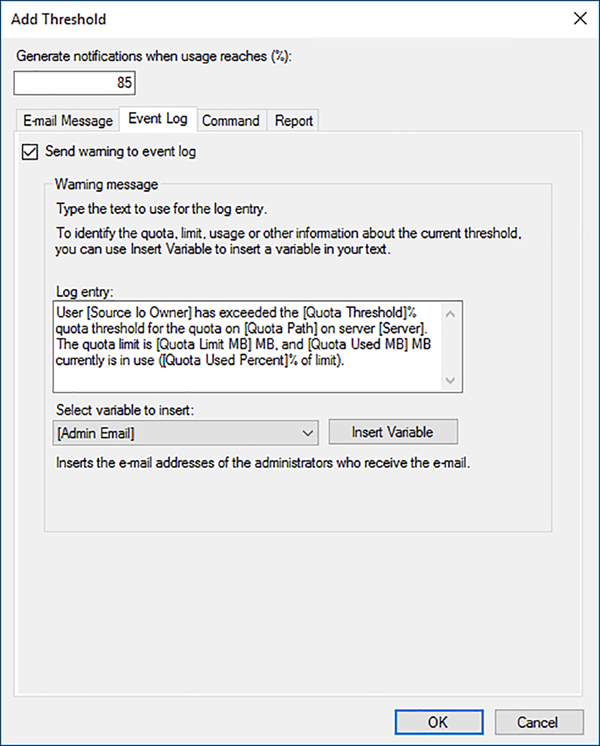
![]() Event Log Select the Send Warning to Event Log checkbox to create a log entry when a user reaches the threshold, as shown in Figure 6-22. You can modify the wording of the log entry in the text box provided.
Event Log Select the Send Warning to Event Log checkbox to create a log entry when a user reaches the threshold, as shown in Figure 6-22. You can modify the wording of the log entry in the text box provided.
![]() Command Select the Run This Command or Script checkbox to specify a program or script file that the system should execute when a user reaches the threshold, as shown in Figure 6-23. You can also specify command arguments, a working directory, and the type of account the system should use to run the program or script.
Command Select the Run This Command or Script checkbox to specify a program or script file that the system should execute when a user reaches the threshold, as shown in Figure 6-23. You can also specify command arguments, a working directory, and the type of account the system should use to run the program or script.

![]() Report Select the Generate Reports checkbox, and then select the checkboxes for the reports you want the system to generate, as shown in Figure 6-24. You can also specify that the system email the selected reports to an administrator or to the user who exceeded the threshold.
Report Select the Generate Reports checkbox, and then select the checkboxes for the reports you want the system to generate, as shown in Figure 6-24. You can also specify that the system email the selected reports to an administrator or to the user who exceeded the threshold.

10. Click OK to close the dialog box and add the new threshold to the Notification Thresholds list on the Create Quota Template dialog box.
11. Repeat steps 7–10 to create additional thresholds, if desired. When you have created all of the thresholds you need, click OK to create the quota template.
12. Close the File Server Resource Manager console.
Using quota templates simplifies the process of managing quotas, in much the same way as assigning permissions to groups, rather than users. If you use a template to create quotas, and you want to change the properties of all of your quotas at once, you can simply modify the template, and the system applies the changes to all of the associated quotas automatically.
Creating quotas
After you have created your quota templates, you can create the quotas themselves. To create a quota, use the following procedure.
1. In the FSRM console, expand the Quota Management node, right-click the Quotas folder and, from the context menu, select Create Quota. The Create Quota dialog box appears, as shown in Figure 6-25.

2. In the Quota Path text box, type or browse to the name of the volume or folder for which you want to create a quota.
3. Select one of the following application options.
![]() Create quota on path Creates a single quota for the specified volume or folder.
Create quota on path Creates a single quota for the specified volume or folder.
![]() Auto apply template and create quotas on existing and new subfolders Causes FSRM to automatically create a quota, based on a template, for each subfolder in the designated path, and for every new subfolder created in that path.
Auto apply template and create quotas on existing and new subfolders Causes FSRM to automatically create a quota, based on a template, for each subfolder in the designated path, and for every new subfolder created in that path.
4. Select one of the following properties options:
![]() Derive properties from this quota template Configures the quota using the settings of the template you select from the drop-down list.
Derive properties from this quota template Configures the quota using the settings of the template you select from the drop-down list.
![]() Define custom quota properties Enables you to specify custom settings for the quota. Clicking the Custom Properties button opens a Quota Properties dialog box for the selected volume or folder, which contains the same controls as the Create Quota Template dialog box.
Define custom quota properties Enables you to specify custom settings for the quota. Clicking the Custom Properties button opens a Quota Properties dialog box for the selected volume or folder, which contains the same controls as the Create Quota Template dialog box.
5. Click Create. The new quota appears in the console’s details pane.
Even if you do not install the File Server Resource Manager role service, a different type of quota is available on NTFS volumes. However, these NTFS quotas are limited to controlling storage on entire volumes, on a per-user basis. When you create FSRM quotas for volumes or folders, they apply to all users. NTFS quotas are also limited to creating event log entries only, while FSRM quotas can also send email notifications, execute commands, and generate reports, as well as log events.
Configure file screens
FSRM, in addition to creating storage quotas, enables administrators to create file screens, which restrict access to storage by preventing users from saving specific types of files on a server drive. Administrators typically use file screening to keep large audio and video files off of server drives because they can consume a lot of space and most users do not need them to complete their work. Obviously, in an organization that utilizes these types of files, screening them would be inappropriate, but you can configure FSRM to screen files of any type.
The process of creating file screens is similar to that of creating storage quotas. You choose the types of files you want to screen and then specify the actions you want the server to take when a user attempts to store a forbidden file type. As with quotas, the server can send emails, create log entries, execute commands, and generate reports. Administrators can also create file screen templates that simplify the process of deploying file screens throughout the enterprise.
To create a file screen, use the following procedure.
1. In FSRM, expand the File Screening Management node and select File Screens. Then, right-click the File Screens container and, from the context menu, select Create File Screen. The Create File Screen dialog box appears, as shown in Figure 6-26.

2. In the File Screen Path text box, type or browse to the name of the volume or folder you want to screen.
3. Select one of the following properties options:
![]() Derive properties from the file screen template Configures the file screen using the settings of the template you select from the drop-down list.
Derive properties from the file screen template Configures the file screen using the settings of the template you select from the drop-down list.
![]() Define custom file screen properties Enables you to specify custom settings for the file screen. Clicking the Custom Properties button opens a File Screen Properties dialog box for the selected volume or folder, which contains the Settings tab shown in Figure 6-27, plus the same Email Message, Event Log, Command, and Report tabs as the Quota Properties dialog box.
Define custom file screen properties Enables you to specify custom settings for the file screen. Clicking the Custom Properties button opens a File Screen Properties dialog box for the selected volume or folder, which contains the Settings tab shown in Figure 6-27, plus the same Email Message, Event Log, Command, and Report tabs as the Quota Properties dialog box.

4. Click Create. The new file screen appears in the console’s details pane.
You can also create file screen exceptions, which override the file screening rules inherited from a parent folder. For example, if you are screening out audio and video files from a particular volume, and you need to store these types of files in one folder, you can create an exception only for that folder.
Configure Storage Reports
Reporting is one of the most important tools for efficient storage management. File Server Resource Manager can generate a variety of reports that enable administrators to examine the state of their file server volumes and identify transgressors of company storage policies.
FSRM can create the following report types:
![]() Duplicate Files Creates a list of files that are the same size and have the same last modified date.
Duplicate Files Creates a list of files that are the same size and have the same last modified date.
![]() File Screening Audit Creates a list of the audit events generated by file screening violations for specific users during a specific time period.
File Screening Audit Creates a list of the audit events generated by file screening violations for specific users during a specific time period.
![]() Files By File Group Creates a list of files sorted by selected file groups in the File Server Resource Manager console.
Files By File Group Creates a list of files sorted by selected file groups in the File Server Resource Manager console.
![]() Files By Owner Creates a list of files sorted by selected users that own them.
Files By Owner Creates a list of files sorted by selected users that own them.
![]() Files by Property Creates a list of files sorted by the values of a specified classification property
Files by Property Creates a list of files sorted by the values of a specified classification property
![]() Folders By Property Creates a list of folders sorted by the values of a specified secure classification property
Folders By Property Creates a list of folders sorted by the values of a specified secure classification property
![]() Large Files Creates a list of files conforming to a specified file spec that are a specified size or larger.
Large Files Creates a list of files conforming to a specified file spec that are a specified size or larger.
![]() Least Recently Accessed Files Creates a list of files conforming to a specified file spec that have not been accessed for a specified number of days.
Least Recently Accessed Files Creates a list of files conforming to a specified file spec that have not been accessed for a specified number of days.
![]() Most Recently Accessed Files Creates a list of files conforming to a specified file spec that have been accessed within a specified number of days.
Most Recently Accessed Files Creates a list of files conforming to a specified file spec that have been accessed within a specified number of days.
![]() Quota Usage Creates a list of quotas that exceed a specified percentage of the storage limit.
Quota Usage Creates a list of quotas that exceed a specified percentage of the storage limit.
Using the FSRM console, you can generate reports on the fly or schedule their creation on a regular basis. To schedule a report, use the following procedure.
1. Select the Storage Reports Management node. Then right-click Storage Reports Management and, from the context menu, select Schedule a New Report Task. The Storage Reports Task Properties dialog box appears, as shown in Figure 6-28.
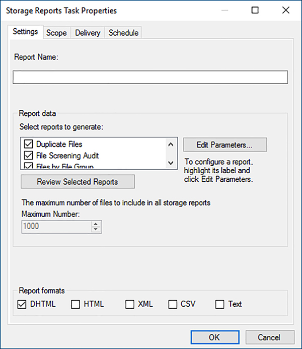
2. On the Settings tab, in the Report Data box, select the reports that you want to generate. When you select a report and click Edit Parameters, a Report Parameters dialog box appears, in which you can configure the parameters for that specific report.
3. In the Report Formats box, select the checkboxes for the formats you want FSRM to use when creating the reports.
4. On the Scope tab, select the checkboxes corresponding to the data types you want the report to include.
5. Click Add and, in the Browse For Folder dialog box that appears, select the volume or folder on which you want a report. Repeat this step to select multiple volumes or folders, if desired.
6. If you want FSRM to send the reports to administrators via email, click the Delivery tab and select the Send Reports To The Following Administrators checkbox. Then enter one or more email addresses (separated by semicolons) in the text box.
7. Click the Schedule tab and select the time when you want FSRM to run the reports. Then, select the frequency of the reports by selecting Weekly or Monthly, and/or the days of the week to run the report.
8. Click OK to close the Storage Reports Task Properties dialog box and add the new report to the schedule, as shown in Figure 6-29.

The report is now added to the schedule. The system generates it at the specified time.
Configure File Management Tasks
The File Management Tasks folder in FSRM enables administrators to schedule actions to occur on specific files and folders based on specific criteria. For example, you can create a task that cause all files in a specific folder that have not been accessed in six months to be moved to an archive location. FSRM calls this File Expiration. You can also configure selected files to be encrypted, or execute a custom task on them.
To create a file management task, use the following procedure.
1. In FSRM, select the File Management Tasks node. Then right-click File Management Tasks and, from the context menu, select Create File Management Task. The Create File Management Task dialog box appears.
2. On the General tab, specify a Task Name and (optionally) a Description. Make sure the Enabled checkbox is selected.
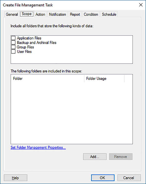
3. On the Scope tab, shown in Figure 6-30, specify the files or folders you want to manage, by selecting from the file type checkboxes and/or clicking Add to add files or folders to the list.
4. On the Action tab, use the Type drop-down list to select one of the following actions to be taken on the files in the scope. Each selection presents a different set of the controls on the tab.
![]() File Expiration Causes the files in the scope to be moved to a specified location when they meet the selected conditions.
File Expiration Causes the files in the scope to be moved to a specified location when they meet the selected conditions.
![]() Custom Enables you to configure an external program to run against the files in the scope when they meet the selected conditions. The dialog box supplies controls (shown in Figure 6-31) that enable you to specify an executable to run and command line arguments, as well as select the account the system should use to execute the program.
Custom Enables you to configure an external program to run against the files in the scope when they meet the selected conditions. The dialog box supplies controls (shown in Figure 6-31) that enable you to specify an executable to run and command line arguments, as well as select the account the system should use to execute the program.

![]() RMS Encryption Causes FSRM to encrypt the files in the scope when they meet the selected conditions. The dialog box supplies controls that enable you to grant access control permissions to specific users.
RMS Encryption Causes FSRM to encrypt the files in the scope when they meet the selected conditions. The dialog box supplies controls that enable you to grant access control permissions to specific users.
5. On the Notification tab, you can specify who should be notified of impending file management actions, using email messages, event log entries, or external commands.
6. On the Report tab, you specify the types of logs and reports FSRM should maintain on the file maintenance task.
7. On the Condition tab, shown in Figure 6-32, you specify the criteria the system uses to select files in the scope for management. You can create conditions based on classification properties you have created in FSRM; file creation, modification, and last accessed dates; or file name patterns using wildcard characters.

8. On the Schedule tab, you select the time when you want FSRM to execute the file maintenance task and the frequency when the task should be repeated, by selecting Weekly or Monthly, and/or the days of the week.
9. Click OK to close the dialog box and create the new file management task.
The task appears in the File Management Tasks pane, and execute according to the schedule you specified.
Configure File Classification Infrastructure using FSRM
Since long before Windows, files have had properties that contain information about them, such as who created them and the date they were created and last modified. The File Classification Infrastructure (FCI) in FSRM enables administrators to create additional properties for files, based on the specific needs of the organization. You can, for example, create a classification property called Security Level and assign it the values High, Medium, and Low. By classifying your files using these property values, you can run a file management task in FSRM to encrypt all documents with a High Security Level.
FCI is more than just additional properties that you can manually configure on individual files, however. It would hardly be practical for administrators to have to set the Security Level property value on thousands of files individually. FCI also includes classification rules, which can automatically assign values to specific properties based on the contents of a file. For example, you can create a rule that scans document files for the word “confidential” and, if it appears more than five times, assigns the file the High value for the Security Level property.
The process of implementing FCI in File Server Resource Manager consists of two steps: creating classification properties and creating classification rules.
Creating classification properties
When you create a classification property in FSRM, you specify the type of data that the property contains and, in some cases, the possible values for the property.
Note Local Classification Properties
When you create classification properties in FSRM, they are stored and applied locally on the server. If you move a classified file to a server that does not have the same properties configured, then any classification information in the file is lost. In Windows Server 2016, it is also possible to create domain-wide properties that are stored in Active Directory, making them available to all of the Windows servers in the domain. This option is discussed later in the chapter.
To create a local classification property in FSRM, use the following procedure:
1. In FSRM, expand the Classification Management node and select Classification Properties. Three default properties appear in the console.
2. Right-click Classification Properties and, from the context menu, select Create Local Property. The Create Local Classification Property dialog box appears.
3. Specify a Name and Description for the new property, and use the Property Type drop-down list (shown in Figure 6-33) to select from the following types:

![]() Yes/No Indicates that the property value contains only the value Yes or the value No.
Yes/No Indicates that the property value contains only the value Yes or the value No.
![]() Date-time Indicates that the property value contains only a timestamp specifying the date and time of an event.
Date-time Indicates that the property value contains only a timestamp specifying the date and time of an event.
![]() Number Indicates that the property value contains only a simple number.
Number Indicates that the property value contains only a simple number.
![]() Multiple Choice List Specifies a list of values that the property can contain, with the ability to choose multiple values, such as a list of file types, several of which can apply to a single file.
Multiple Choice List Specifies a list of values that the property can contain, with the ability to choose multiple values, such as a list of file types, several of which can apply to a single file.
![]() Ordered List Specifies a list of values that the property can contain, with priorities established by a specific order, such as High, Medium, and Low for a property indicating a security level.
Ordered List Specifies a list of values that the property can contain, with priorities established by a specific order, such as High, Medium, and Low for a property indicating a security level.
![]() Single Choice Specifies a list of values that the property can contain, with the ability to choose only one value, such as a list of countries of origin, only one of which can apply to a single file.
Single Choice Specifies a list of values that the property can contain, with the ability to choose only one value, such as a list of countries of origin, only one of which can apply to a single file.
![]() String Indicates that the property contains only a specified text string, such as the contact email address of the person responsible for the security of the file.
String Indicates that the property contains only a specified text string, such as the contact email address of the person responsible for the security of the file.
![]() Multi-String Indicates that the property contains a list of specified text strings, such as multiple email addresses.
Multi-String Indicates that the property contains a list of specified text strings, such as multiple email addresses.
4. Depending on the Property Type you choose, you might have to enter the possible values for the property. For example, in the Ordered List property type, you enter the range of values in the array provided, as shown in Figure 6-34.

5. Click OK to create the property and add it to the console.
Creating classification rules
Creating classification properties specifies the type of data that the new file properties contain and, in some cases, the property values themselves. However, that process does not specify how the system determines what property value (or values) it should assign to a particular file. For this to occur, you must create classification rules in FSRM.
To create a classification rule, use the following procedure.
1. In FSRM, select the Classification Rules node. Right-click Classification Rules and, from the context menu, select Create Classification Rule. The Create Classification Rule dialog box appears.
2. Specify a Rule Name and Description for the new rule.
3. On the Scope tab, specify the files or folders to which you want to apply the rule, by selecting from the file type checkboxes and/or clicking Add to add files or folders to the list.
4. On the Classification tab, you select a Classification Method. Then, you specify the property, and the value for that property, that you want to apply with the rule, as shown in Figure 6-35.

5. Click Configure to open the Classification Parameters dialog box. This is where you specify how the system should identify a file as conforming with the property value you selected. In this example, the organization always inserts the word Confidential in the header and footer on each page of all sensitive documents. Therefore, this rule uses the Content Classifier method to scan the files in the scope for the word Confidential. If the word appears five or more times in a file, the Security Level property is assigned the value High.
6. In the Parameters area, in the Expression text box, type the word Confidential and set the Minimum Occurrences value to 5, as shown in Figure 6-36. Then click OK to close the Classification Parameters dialog box.

7. Click OK to create the rule and close the Create Classification Rule dialog box.
Once you have created your properties and rules, you can select Configure Classification Schedule in the FSRM console’s Action pane to specify when the classification should occur. You can also select Run Classification With All Rules Now to execute the classification process immediately.
Once the classification is completed, every file in the scope should list the properties you created on the classification tab of its Properties sheet. For files that conform to the parameters of the rule you created, the Security Level property is assigned the value High, as shown in Figure 6-37.

![]() Quick check
Quick check
You have created a set of classification properties in File System Resource Manager on one of your file servers, and assigned the properties to server files using classification rules. Now that the process is running successfully, you want to implement it on your other file servers. How can you do this?
![]() Quick check answer
Quick check answer
The Classification Management tools in FSRM operate on the local server only. To create and deploy properties on multiple servers, you must use Dynamic Access Control to create resource properties in Active Directory Administrative Center, package them as resource property lists, and deploy them to your file servers using Windows PowerShell.
Implement Work Folders
Work Folders is a Windows Server 2016 role service that enables users to synchronize their work documents with a central server. This enables the users to access their files from any device, anywhere, and enables administrators to protect the server copies of the files from accidental deletion or other damage.
A simple Work Folders deployment consists of a single file server running the Work Folders role server, on which you have created a sync share, which is where the users’ work files are located. Onsite users configure their workstations to access the sync share, or administrators configure the workstations remotely using Group Policy.
In a more complex deployment, there might be multiple Work Folders servers at different sites, in which case you must see to it that each user is directed to the one server that contains his or her files. You can do this with Group Policy settings, or have users search for the correct server by supplying their email addresses. You might also have users that want to access their work files from home or while traveling, in which case you must set up a reverse proxy, so that they can connect to the Work Folders server from the Internet.
Installing the Work Folders role service
To install the Work Folders role service, you use the Add Roles and Features Wizard in Server Manager. Work Folders is part of the File and Storage Services role, and is located under File and iSCSI Services. The installation prompts you to install the IIS Hostable Web Core feature, which is a minimal version of Internet Information Services (IIS).
To use Work Folders in a production environment, you have to obtain a Secure Sockets Layer (SSL) certificate for the server and bind it to the Default Web Site created by the IIS Hostable Web Core. You do this using the Internet Information Services (IIS) Manager console on another computer to connect to the Web Folders server.
To install Work Folders using PowerShell instead, you use the Install-WindowsFeature cmdlet, as follows:
install-windowsfeature -name fs-syncshareservice
Creating Work Folders Groups
Work folders requires dedicated domain security groups, as follows:
![]() User groups For each sync share you plan to create, create a domain security group whose members are the users that are permitted to use that share
User groups For each sync share you plan to create, create a domain security group whose members are the users that are permitted to use that share
![]() Administrator group If you plan to deploy multiple Work Folders servers on your network, create a domain security group whose members are the Work Folders administrators. The members of this group are able to modify a user object attribute specifying the server that each user uses.
Administrator group If you plan to deploy multiple Work Folders servers on your network, create a domain security group whose members are the Work Folders administrators. The members of this group are able to modify a user object attribute specifying the server that each user uses.
You can create the groups using Active Directory Administrative Center, Active Directory Users and Computers, or the New-ADGroup cmdlet in Windows PowerShell.
Creating sync shares
Once you have installed the Work Folder role service, you can create a sync share on the server using Server Manager. To create a sync share, use the following procedure.
1. On the Server Manager Dashboard, click File and Storage ServicesWork Folders. The Work Folders pane appears.
2. From the Task menu, select New Sync Share. The New Sync Share Wizard appears.
3. On the Server and Path page, select the local server. Under Location, select Enter a Local Path and type the path to the folder on a local drive where you want to create the work folders.
4. On the User Folder Structure page, select one of the following options to specify the format of the folders that Work Folders creates for each user:
![]() User Alias Creates folder named for the user account only. This provides compatibility with other data storage solutions, such as Folder Redirection.
User Alias Creates folder named for the user account only. This provides compatibility with other data storage solutions, such as Folder Redirection.
![]() User Alias@domain Creates folder named for the user account with the domain name. This eliminates problems caused by duplicate account names in different domains.
User Alias@domain Creates folder named for the user account with the domain name. This eliminates problems caused by duplicate account names in different domains.
5. On the Sync Share Name page, specify a Name and Description for the sync share.
6. On the Sync Access page, add the user groups you created that contain the individuals who use Work Folders.
7. On the PC Security Policies page, specify whether you want to encrypt the Work Folders and whether you want to secure users’ devices by locking their screens after fifteen minutes and requiring a six-character password unlock it again. This setting also implements a device lockout after ten unsuccessful unlock attempts.
8. Review your settings on the Confirmation page and click Create.
9. When the sync share is created, click Close.
You can also create a sync share using the NewSyncShare cmdlet in Windows PowerShell, as in the following example:
new-syncshare "work" c:work –user "domain users"
Configuring Work Folders clients
Once the Work Folders server is configured, you can set up the client half of the application on your workstations. The Windows workstation operating systems include a Work Folders application in the Control Panel, which users can employ to set up Work Folders themselves. To perform a mass deployment, administrators can use Group Policy settings.
Note Allowing Unsecured Connections
Before your production clients can connect to the Work Folders server and begin syncing, you must obtain an SSL certificate and bind it to the Default Web Site on the Work Folders server. To evaluate Work Folders in a lab environment, you can configure a client workstation to allow an unsecured connection to the server by modifying the registry with the following command:
Reg add HKLMSOFTWAREMicrosoftWindowsCurrentVersionWorkFolders /v
AllowUnsecureConnection /t REG_DWORD /d 1
To configure Work Folders client manually, use the following procedure:
1. Open Control Panel and, in System and Security, launch the Work Folders application.
2. Click Set Up Work Folders. The Enter Work Email page appears, as shown in Figure 6-38.

3. Type the email address of a user that is a member of the users group you created earlier. Alternatively, you can click the Enter a Work Folders URL Instead link and type the URL of the Work Folders server to use. The format for the server’s URL is https://servername.domain.com.
4. After authenticating as the user, on the Introducing Work Folders page, you can click Change to modify the default location of the Work Folders directory on the local drive.
5. The Security Policies page lists the changes that administrators can make to the PC through the Work Folders feature. Select the I Accept These Policies On My PC checkbox.
6. Click Set Up Work Folders. The Work Folders Has Started Syncing With This PC page appears.
The setup process creates a folder on both the client and the server, the contents of which are synchronized. At this point, when there are no changes to the files in the client’s Work Folders directory, the client attempts to sync with the server every ten minutes, seeking modifications to its folder on the server. Adding or modifying a file in the client Work Folder directory triggers an immediate sync. When the client initiates a sync with the server, the server informs the client of any changes to files in the server folder, and transfers them as needed.
A user can then log on from any workstation, set up Work Folders, and establish a sync relationship with the Work Folders server. The folders on the servers and the workstations and then remain synchronized.
Configure user and device claim types
File Server Resource Manager enables you to classify the files stored on a server by creating classification properties and applying property values using classification rules. Dynamic Access Control (DAC) is an Active Directory technology that take this concept farther. Using DAC you can configure Active Directory to automatically assign access control permissions based on more complex scenarios than were ever possible using just NTFS and share permissions, and which extend to an entire domain, rather than a single server.
DAC components
DAC is based on three components that work together to define these scenarios: resource properties, claim types, and central access rules.
For example, you might have confidential files stored on a server that are flagged as such using resource properties. These are similar to the classification properties in FSRM, except that they are stored in Active Directory. Windows Server 2016 includes a large collection of resource properties that you can assign to files, or you can create your own. You then deploy them to your file servers using Windows PowerShell.
These confidential files are to be accessible only by corporate users at the director level or above. Those users are identified by user claims, which are attributes that specify characteristics of the network users, such as their ranks in the corporate hierarchy.
The confidential files must also be accessible only by users working in the corporate home office in Chicago. The company workstations, therefore, can be identified by device claims that specify their locations. User and device claims are Active Directory attributes associated, in this case, with the user and computer objects. You can create claim types based on existing object attributes, or you can extend the Active Directory schema to create new ones.
The third component, central access rules, ties the DAC components together by defining the conditional statements that govern the access control assignments. To define the conditions for access to the confidential files mentioned earlier, you might create a central access rule that states that access to the confidential files is to be granted only when the following conditions are met:
![]() File resource property: Security = High
File resource property: Security = High
![]() User claim: Rank = Director
User claim: Rank = Director
![]() Computer claim: Location = Chicago
Computer claim: Location = Chicago
In other words, the central access rule states that when the Security resource property of a file is High, access is granted only when the Rank user claim is at least Director and the Location computer claim is Chicago.
This is a simple example of the types of scenarios you can define using DAC. You can create any number of resource properties, user claims, and device claims, and combine them in central access rules that are far more complex than this one. A collection of central access rules is called a central access policy (CAP), which you deploy using Group Policy settings.
 Exam Tip
When preparing for the 70-744 exam, be sure to remain conscious of the differences in scope between the local properties and rules that you create in File Server Resource Manager and the domain-based Dynamic Access Control elements that you create in Active Directory Administrative Center, such as claim types, resource properties, and central access rules. The DAC elements are global and available to all of the file servers in the domain. The FSRM rules and properties affect only the local file system. If you want to deploy FSRM rules and properties throughout your network, you must create them on each file server individually.
Creating claim types
To create claim types, and the other DAC elements, you use the Active Directory Administrative Center console, as in the following procedure.
1. Open the Active Directory Administrative Center from Server Manager’s Tools menu.
2. In the left pane, click the Dynamic Access Control arrow and select Claim Types. The Claim Types pane appears, with only a single claim type listed.
3. In the Tasks pane, click New | Claim Type. The Create Claim Type dialog box appears.
4. Under Source Attribute, select an Active Directory attribute from the list, using the Filter search box to locate one, if necessary, as shown in Figure 6-39.

5. In the Display Name text box, specify a friendly name for the claim type.
6. Select the User or Computer checkbox to specify the object type to associate with the claim.
7. In the left pane, click Suggested Values and select the The Following Values Are Suggested option.
8. Click Add. The Add a Suggested Value dialog box appears.
9. In the Value text box, type one of the possible values for the attribute you selected. In the Display Name text box, type the name by which you want the value to appear. For example, if you are creating a claim type from the Department attribute, you might want to add suggested values such as Sales, Marketing, and IT.
10. Click OK to add the suggested value and repeat steps 8 to 9 to create additional values.
11. Click OK to close the dialog box and create the claim type.
Create and configure resource properties and lists
Resource properties are similar in function to the classification properties you can create in File Server Resource Manager. They contain metadata that you can add to files and folders. The primary difference is that resource properties are stored in Active Directory, and are therefore available to any file server in the domain. This prevents you from having to create the same classification properties in FSRM on every file server.
Later, you can create central access rules that associate user and device claims with resource properties, to determine what permissions should be applied to the files.
As with claim types, you create resource properties in Active Directory Administrative Center. Then, you package the resource properties into resource property lists, which you deploy to your file servers.
Creating resource properties
To create resource properties, use the following procedure.
1. Open the Active Directory Administrative Center from Server Manager’s Tools menu.
2. In the left pane, click the Dynamic Access Control arrow and select Resource Properties. The Resource Properties pane appears, with a list of 16 predefined properties.
3. In the Tasks pane, click New | Resource Property. The Create Resource Property dialog box appears, as shown in Figure 6-40.

4. In the Display Name text box, type a name for a property.
5. In the Value Type drop-down list, select an option that controls the nature of the property’s values. The Value Type options are essentially the same as the Property Types in FSRM.
6. In the Suggested Values box, click Add. The Add a Suggested Value dialog box appears.
7. In the Value text box, type one of the possible values for the property. In the Display Name text box, type the name by which you want the value to appear. For example, if you are creating a resource property called Security Level, you might want to add suggested values such as High, Medium, and Low.
8. Click OK to add the value to the property.
9. Repeat steps 6 to 8 to create additional property values
10. Click OK to create the new resource property and add it to the list.
Newly-created resource properties are enabled by default, however, the predefined resource properties are not. To use one of the existing properties in the list, select it and click Enable in the Tasks list. You can also click Properties to open the Properties sheet for the selected resource property and modify it, such as by adding values.
For example, if you enable the Department resource property and examine its properties, you find that is already populated with a list of standard department names as values. To use this resource property, you might want to modify this list by adding or removing department name values.
Creating resource property lists
All of the resource properties you create are stored in the Active Directory database. To propagate them to the File Server Resource Manager console on your file servers, you must package them into resource property lists.
To create a new resource property list, use the following procedure.
1. Open the Active Directory Administrative Center from Server Manager’s Tools menu.
2. In the left pane, click the Dynamic Access Control arrow and select Resource Property Lists. The Resource Property Lists pane appears, with one predefined list.
3. In the Tasks pane, click New | Resource Property List. The Create Resource Property List dialog box appears, as shown in Figure 6-41.

4. In the Name text box, type a name for the list.
5. Click Add. A Select Resource Properties dialog box appears.
6. In the list provided, select each property you want to add to the list and click the right arrow to add it to the Add the Following Resource Properties box.
7. Click OK to add the selected properties to the list.
8. Click OK to close the Create Resource Property List dialog box and create the new list.
Once you have created a resource property list, you can deploy it to a file server by opening a Windows PowerShell session with administrative privileges on the file server and running the following cmdlet, with no parameters.
Update-FSRMClassificationPropertyDefinition
Now, if you open FSRM and look at the Classification Properties pane, you see that the resources properties you created in Active Directory Administrative Center appear on the file server with a Global scope, as shown in Figure 6-42. You can now use these properties as you would the local ones you created in FSRM, assigning them to files and folders manually or by using local classification rules.

Create and configure central access rules and policies
Once you have created claim types and resource properties and have classified your files and folders, you can create central access rules that tie these elements together. A central access rule (CAR) has two primary functions, as follows:
![]() Selects the classified files and folders to which access control lists are applied
Selects the classified files and folders to which access control lists are applied
![]() Selects the users to be authorized, based on their claim types
Selects the users to be authorized, based on their claim types
To deploy CARs to your file servers, you must package them into central access policies (CAPs), which you add to Group Policy Settings.
1. Open the Active Directory Administrative Center from Server Manager’s Tools menu.
2. In the left pane, click the Dynamic Access Control arrow and select Central Access Rules. The Central Access Rules pane appears.
3. In the Tasks pane, click New | Central Access Rule. The Create Central Access Rule dialog box appears, as shown in Figure 6-43.

4. In the Name text box, type a name for the rule.
5. In the Target Resources box, click Edit to open a Central Access Rule dialog box.
6. Click Add a Condition. Five drop-down lists appear, in which you select the criteria by which the rule selects the files and folders to which it assigns permissions. These drop-down lists are populated with the resource properties you have created and their values.
7. Select criteria from the drop-down lists to define an expression identifying the resources you want the rule to modify. For example, if you select the Security Level property in the second drop-down list, the values you defined for that property appear in the fifth drop-down list, as shown in Figure 6-44. If you select the value High, you are creating an expression that says “If the file’s Security Level property value is equal to High, then select that resource.”

8. Optionally, you can click Add a Condition again to create another expression, and select a Boolean operator, as shown in Figure 6-45. This example creates an expression that says, “If the file’s Security Level property value is equal to High and the file exists in the Administration department, then select that resource.”

9. Click OK to close the dialog box and add the expression to Target Resources box.
10. In the Permissions box, select the Use the Following Permissions as Current Permissions option.
11. Click Edit to open the Advanced Security Settings for Permissions dialog box.
12. Click Add to add users or groups and specify the permissions they should receive to the files or folders selected by the target resources expression. For example, you might grant the Managers group the Allow Read and Allow Write permissions, and the Directors group the Allow Full Control permission, as shown in Figure 6-46.

13. Click OK to add the permissions you created to the Permissions list.
14. Click OK to close the dialog box and add the new rule to the Central Access Rules pane.
Creating central access policies
A central access policy (CAP) is simply a package that contains one or more central access rules for deployment. To create a CAP, use the following procedure.
1. Open the Active Directory Administrative Center from Server Manager’s Tools menu.
2. In the left pane, click the Dynamic Access Control arrow and select Central Access Policies. The Central Access Policies pane appears.
3. In the Tasks pane, click New | Central Access Policy. The Create Central Access Policy dialog box appears, as shown in Figure 6-47.

4. In the Name text box, type a name for the policy.
5. In the Member Central Access Rules box, click Add to open a Create Central Access Policy dialog box.
6. Select the rules you want to add to the policy and click the right arrow to add them to the Add the Following Central Access Rules list.
7. Click OK to add the rules you selected to the Member Central Access Rules box.
8. Click OK to close the dialog box and create the CAP.
Deploying central access policies
As with claim types and resource properties, central access rules and central access policies are stored in Active Directory. To deploy the CAPs you have created to the file servers in your domain, you use Group Policy settings.
The select the CAPs for deployment, use the following procedure:
1. Open a Group Policy object in the Group Policy Object editor console and browse to the Computer Configuration/Policies/Windows Settings/Security Settings/File System/Central Access Policy folder.
2. Right-click the folder and, from the context menu, select Manage Central Access Policies. The Central Access Policies Configuration dialog box appears.
3. In the Available Central Access Policies list, select the CAPs you want to deploy and click the Add button, as shown in Figure 6-48.

4. Click OK to create settings for the CAPs you selected.
5. Link the GPO to appropriate domain, site, or organizational unit objects, so that it is deployed to all of your file servers.
6. In the Default Domain Controllers GPO, browse to the Computer Configuration/Policies/Administrative Templates/System/KDC folder.
7. Open the Properties sheet for the KDC Support for Claims, Compound Authentication and Kerberos Armoring policy setting.
8. Select the Enabled option, and in the drop-down list, select Supported and click OK.
9. Run the gpupdate /force command on your domain controllers and your file servers, to apply the Group Policy objects.
To confirm that your selected CAPs have been applied to your file servers, do the following:
1. On your file server, open the Properties sheet for a file which the CAR should have selected.
2. Click the Security tab.
3. Open the Advanced Security Settings dialog box.
4. Click the Central Policy tab. Your CAP should be available in the Central Policy drop-down list, as shown in Figure 6-49.

Implement policy changes and staging
Creating and managing all of the different elements required for a DAC implementation can be complicated, and any system that automatically manipulates access control lists has the potential for disaster if it is incorrectly configured. For this reason, DAC includes a staging capability, which enables you to deploy central access policies without actually modifying the permissions involved.
When you create a central access rule, the default option in the Permissions section is Use Following Permissions as Proposed Permissions. Leaving this option selected in your CARs causes the resulting CAPs to generate access requests for the targeted resources and log them in the system’s event logs. You can then examine the logs in Event Viewer to determine whether the correct resources have been targeted and the correct permissions proposed.
In addition to leaving the staging option selected in your CARs, you must also enable auditing for the proposed permissions by configuring Group Policy settings in a GPO deployed to your file servers. In the GPO, browse to the Computer Configuration/Policies/Windows Settings/Security Settings/Advanced Audit Policy Configuration/Audit Policies/Object Access container and enable Success and Failure auditing for the following two policies:
![]() Audit Central Access Policy Staging
Audit Central Access Policy Staging
![]() Audit File System
Audit File System
Once the auditing policies are in place, and you have enabled auditing of the files or folders on the Auditing tab of their Advanced Security Settings dialog boxes, you should monitor the Security event log for Auditing Event 4818: Proposed Central Access Policy Does Not Grant the Same Access Permissions as the Current Central Access Policy.
Configure file access auditing
Monitoring resource usage, and attempted usage, is a critical part of maintaining a secure workplace, and the auditing capabilities of Windows Server 2016 enable administrators to configure granular targets for resource monitoring. This prevents the need for administrators to pore over thousands of event log entries looking for the ones that indicate a potential problem.
You have already studied the process of enabling specific audit policies in Group Policy objects elsewhere in this book. However, Dynamic Access Control can contribute to these auditing capabilities. You can use the claim types and resource properties you create in Active Directory Administrative Center to control the circumstances under which file system resources generate auditing events.
To audit file access activities, you must first enable the Audit File System setting in the Computer Configuration/Policies/Windows Settings/Security Settings/Advanced Audit Policy Configuration/Audit Policies/Object Access container of a Group Policy object. Then, you must enable auditing in the properties of the files and folders that you want to monitor.
You enable auditing of a file or folder by opening its Properties sheet, clicking the Security tab, and opening the Advanced Security Settings dialog box. On the Auditing tab of this dialog box, you create auditing entries in which you select a security principal—that is, a user or group—that you want to audit, specify whether you want to audit success or failure or both, and select the specific permissions that you want to audit for that principal.
Beneath the Basic Permissions list, however, is an often-ignored box that enables you to add a condition that limits the scope of the auditing entry. These conditions take the form of expressions that you create, much as you did when creating central access rules, as described earlier in this chapter. Clicking the Add a Condition link causes a series of drop-down lists to appear that, as in Active Directory Administrative Center, are populated with the DAC claim types, resource properties, and values you have created.
For example, the first drop-down list enables you to select Device, Resource, or User, as shown in Figure 6-50. When you select one of these, the other drop-down lists are populated with the values of the element you select. For example, when you select Resource in the first list, the second list contains the resource properties you have created. When you select a resource property, the last list contains the values you configured for that property.

This enables you to create expressions that specifically define the elements that the system audits. Instead of auditing all file accesses to a particular folder by everyone in the Managers group, for example, you can create an expression that audits only members of the Managers group that have the value High in their Security Level claim type. As with central access rules, you can also create multiple conditions and join them with Boolean operators, to create compound expressions.
Perform access-denied remediation
When a user attempts to open a file and is denied access because of insufficient permissions, there was a time when he or she had no recourse but to give up or try to locate an administrator responsible for that file. Windows Server 2016 includes a feature called access-denied remediation (also called access-denied assistance) that addresses this issue by enabling administrators to customize the message displayed to users when they are denied access.
To enable access-denied remediation, you can use File Server Resource Manager to configure a single file server, or use Group Policy settings for a domain-wide solution. To configure access-denied remediation on a single server with FSRM, use the following procedure.
1. Open File Server Resource Manager and, in the Actions pane, click Configure Options. The File Server Resource Manager Options dialog box appears.
2. Click the Access-Denied Assistance tab, as shown in Figure 6-51.

3. Select the Enable Access-Denied Assistance checkbox.
4. Optionally, modify the Access Denied message that appears, to provide users with specific instructions for gaining access to the resource.
5. If you want to enable users to request assistance by generating emails, Click Configure Email Requests. The Access-Denied Assistance dialog box appears.
6. Select the Enable Users to Request Assistance checkbox.
7. Enter email addresses in the Recipient List text box and select or clear the Folder Owner and Administrator checkboxes, to specify who should receive the emails.
8. Optionally, modify the message included in the emails.
9. Click OK to close the Access-Denied Assistance dialog box.
10. Click OK to close the File Server Resource Manager Options dialog box.
To configure access-denied assistance for multiple file servers, you must enable settings in a Group Policy object, as in the following procedure.
1. Open a GPO in the Group Policy Management Editor.
2. Browse to the Computer ConfigurationPoliciesAdministrative TemplatesSystemAccess-Denied Assistance folder.
3. Open the Enable Access-Denied Assistance On Client For All File Types dialog box and enable the policy setting.
4. Open the Customize Message For Access-Denied Errors dialog box and enable the policy setting, as shown in Figure 6-52.

5. Enter text to be displayed in the Access Denied message that users receive.
6. To allow users to send emails from the Access Denied message, select the Enable Users To Request Assistance checkbox.
7. Optionally, modify the message included in the emails.
8. Enter email addresses in the Additional Recipients List text box and select or clear the Folder Owner and File Server Administrator checkboxes, to specify who should receive the emails.
9. Click OK to close the dialog box.
10. Deploy the GPO to domain, site, or organizational unit objects containing your file servers.
Chapter summary
![]() Nano Server is a Windows Server 2016 installation option that creates a server with a smaller footprint than Server Core, designed for cloud and virtual machine use.
Nano Server is a Windows Server 2016 installation option that creates a server with a smaller footprint than Server Core, designed for cloud and virtual machine use.
![]() Nano Server has no user interface beyond a rudimentary network configuration capability; you install it by creating a VHD file from a Nano Server image and deploying it on a virtual or physical machine.
Nano Server has no user interface beyond a rudimentary network configuration capability; you install it by creating a VHD file from a Nano Server image and deploying it on a virtual or physical machine.
![]() Containers are virtual operating system environments that enable software developers and other users to create clean installation environment in seconds, using resources shared with the host system.
Containers are virtual operating system environments that enable software developers and other users to create clean installation environment in seconds, using resources shared with the host system.
![]() Windows Server 2016 includes two container implementations: Windows Server Containers, which share the host system kernel; and Hyper-V containers, which have individual kernels provided by the hypervisor, making them more secure.
Windows Server 2016 includes two container implementations: Windows Server Containers, which share the host system kernel; and Hyper-V containers, which have individual kernels provided by the hypervisor, making them more secure.
![]() Using File Server Resource Manager, you can create quotas, to limit user storage space; file screens, to prevent users from storing specific file types; storage reports, to track storage-based activities; and file management tasks, to take action on files based on their contents.
Using File Server Resource Manager, you can create quotas, to limit user storage space; file screens, to prevent users from storing specific file types; storage reports, to track storage-based activities; and file management tasks, to take action on files based on their contents.
![]() The File Classification Infrastructure enables you to assign properties values to files and folders based on rules that evaluate their contents.
The File Classification Infrastructure enables you to assign properties values to files and folders based on rules that evaluate their contents.
![]() Using Work Folders, you can configure user workstations to sync files to file servers, enabling users to access their files from any device and administrators to protect the files with server-based backup and encryption.
Using Work Folders, you can configure user workstations to sync files to file servers, enabling users to access their files from any device and administrators to protect the files with server-based backup and encryption.
![]() Dynamic Access Control is an Active Directory-based technology that enables administrators to define claim types and resource properties, and use them to create central access rules that automatically assign file system permissions.
Dynamic Access Control is an Active Directory-based technology that enables administrators to define claim types and resource properties, and use them to create central access rules that automatically assign file system permissions.
![]() Access-Denied Remediation enables administrators to customize Access Denied messages, to provide users with assistance in accessing files to which they lack permissions.
Access-Denied Remediation enables administrators to customize Access Denied messages, to provide users with assistance in accessing files to which they lack permissions.
Thought experiment
In this thought experiment, demonstrate your skills and knowledge of the topics covered in this chapter. You can find answer to this thought experiment in the next section.
The Human Resources department at Tailspin Toys has a great many documents containing employee Social Security numbers on their file server. You have been asked by your director to implement a solution that encrypts the files.
How can you do what the director asks?
To do as the director asks, you must locate the document files that contain social security numbers and then encrypt them. You can do all of this using File Server Resource Manager on the file server.
1. Install the File Server Resource Manager role service on the file server.
2. In the FSRM console, create a Yes/No classification property called SSN. This property indicates files that contain Social Security numbers.
3. Create a classification rule with the following parameters:
![]() Specifies a scope that includes all of the document folders on the file server
Specifies a scope that includes all of the document folders on the file server
![]() Uses the Content Classifier method to assign the Yes value to the SSN property of a file when it contains the regular expression d{3}-d{2}-d{4}. This is the standard regular expression for a string containing 3 digits, then 2 digits, then 4 digits, separated by hyphens.
Uses the Content Classifier method to assign the Yes value to the SSN property of a file when it contains the regular expression d{3}-d{2}-d{4}. This is the standard regular expression for a string containing 3 digits, then 2 digits, then 4 digits, separated by hyphens.
4. Create a classification schedule that runs weekly and allows continuous classification for new files.
5. Create a file management task with the following parameters:
![]() Specifies a scope that includes all of the document folders on the file server.
Specifies a scope that includes all of the document folders on the file server.
![]() Uses the RMS Encryption action.
Uses the RMS Encryption action.
![]() Contains the condition that the SSN property has the value Yes.
Contains the condition that the SSN property has the value Yes.
![]() Contains a schedule that runs weekly and runs continuously on new files.
Contains a schedule that runs weekly and runs continuously on new files.