
Chapter 10 – Platform Security and Trust
We will bankrupt ourselves in the vain search for absolute security.
—Dwight D. Eisenhower
The Unified Extensible Firmware Interface (UEFI) and Platform Initialization (PI) specifications describe the platform elements that take control of the system across the various restart events. These elements are also responsible for ceding control to hypervisors, operating systems, or staying in the UEFI boot services environment as the “runtime.” These modules and drivers can provide support for various secure boot and trusted computing scenarios.
Beyond the feature drivers and boot flow, the UEFI and PI specifications describe interfaces and binary image encoding of executable modules for purposes of interoperability. This allows for business-to-business engagements, such as a chipset or CPU vendor providing drivers to a system board vendor for purposes of building a whole solution. This is the positive side of the extensibility. The darker side of extensibility, though, entails the need to have some assurance that the final system board design meets various security goals, such as integrity, availability, and confidentiality. In other words, how can the platform manufacturer who ships a system board have confidence that the UEFI and PI modules have been safely composed?
This chapter describes some of the security and trusted computing capabilities. Then it discusses how to construct and integrate elements.
Trust Overview
We begin the discussion of trusted platforms with some background on trust—specifically, the definition of trust, and some related concepts, measurement and security:
![]() Trust. An entity can be trusted if it always behaves in the expected manner for the intended purpose.
Trust. An entity can be trusted if it always behaves in the expected manner for the intended purpose.
![]() Measurement. The process of obtaining the identity of an entity.
Measurement. The process of obtaining the identity of an entity.
![]() Security. Maintenance that ensures a state of inviolability from hostile acts or influences (from http://www.thefreedictionary.com/security).
Security. Maintenance that ensures a state of inviolability from hostile acts or influences (from http://www.thefreedictionary.com/security).
In fact, trust is an amalgam of several elements of the platform that span the enterprise to consumer, including reliability, safety, confidentiality, integrity, and availability, as illustrated in Figure 10.1.

Where should the solution reside, given the problems to be solved and some of the capabilities like security, trust, and measurement to help effect the solution?
In fact, the implementation of trust and security entail a security architecture that spans the entire system, starting at the base with hardware and spanning all of the way to the end-user application.
Figure 10.2 shows all of the layers of a security architecture. The network layer is broken out with a few examples, such as protocols (SSL, IPSec); this chapter does not delve too deeply into this layer. The firmware layer is highlighted to show that a single-layer of security is not sufficient.

In fact, the scope of this chapter largely addresses firmware. Some description of hardware elements and interaction are provided. Figure 10.3 highlights the area that this chapter discusses in more depth.

As seen in Figure 10.3, all layers are important, but if you do not have firmware/ hardware assurance, you cannot have a security architecture. As the logicians would say, it’s “necessary but not sufficient” to have appropriate design in these layers. And as will be described later, the layer of hardware and firmware provide a “root of trust” for the rest of the security architecture.
So now that we have trust, security, measurement, and a layered picture of the security architecture, the goals of the security architecture and assets that are protected are as follows.
The first security goal is integrity, and this entails the protection of content and information from unauthorized modification. The next goal is authenticity, and this provides guarantee or assurance in the source of the code or data. Another important goal is availability, or the ability to ensure behavior and the responsiveness of the system. Availability also protects from destruction or denial of access. And finally, another goal is confidentiality, or the protection of information from unauthorized access.
Through the subsequent discussion of trusted platforms and UEFI, some of these integrity, authenticity, and availability goals will be discussed in more detail.
It is outside the scope of this chapter to describe confidentiality since this is typically a concern of higher-level applications, but errors in lower layers of the trusted platform may imperil this goal. Specifically, this relates to the introduction of vulnerability via a flaw in integrity or authenticity implementations of a layer that wants to provide confidentiality (say an application) when the hardware or firmware or network underneath is errant.
A final item that will be discussed in this chapter is a final goal that spans all of the above, namely assurance. By assurance we mean having some guarantee of the correctness of an implementation. And for this study, assurance will be treated in detail for the case when platform firmware and trusted computing hardware elements are the embodiment of the platform.
And given the trust definition above, we see that these features are especially important in the enterprise, such as a high-end server, where reliability and safety goals are co-equal to the other concerns like integrity and confidentiality.
Trusted Platform Module (TPM) and Measured Boot
In building out the hardware layer of the security architecture, one problem with open platforms is that there hasn’t been a location on the system to have a root of trust. The trusted platform module (TPM) and the infrastructure around this component are an industry attempt to build a series of roots of trust in the platform.
The maintenance and evolution of the capabilities of the TPM are managed through an industry standards body known as the Trusted Computing Group (TCG). The TCG members include systems manufacturers, TPM manufacturers, CPU and chipset vendors, operating system vendors, and other parties that contribute hardware and software elements into a trusted platform. HP and IBM are examples of vendors that span many of these categories. Intel also participates in the TCG as CPU and chipset vendor.
To begin, what is a trusted platform module? It features a series of protected regions and capabilities. Typically, a TPM is built as a microcontroller with integrated flash/ storage that is attached to the LPC bus on PC, but it can also be a virtual device or more deeply integrated in the platform chipset complex. The TPM interacts with system through a host interface. The TPM Interface Specification (TIS) in the TCG PC Client working group describes the memory-mapped I/O interfaces; the TIS is just one such interface. The TPM main specification describes the ordinals or the byte stream of commands that are sent into the TPM. These commands are the required actions that a TPM must carry out in service of the host. Figure 10.4 shows some of the specifications that describe the TPM and its integration into the platform.

The interoperability of the Trusted Computing elements is managed through the Trusted Computing Group (TCG) and a series of specifications. For purposes of this review, the TPM main specification, platform design guides, protection profiles, and the UEFI collateral will be of interest, as highlighted above.
Figure 10.6 shows an instance of a TPM diagrammatically. Given the existence of the specifications mentioned earlier, multiple vendors can provide conformant instances of this technology with the ability to differentiate their implementations.

Figure 10.6 is a picture of the elements that are typically found within a TPM. The protected execution and storage of the TPM allow for hosting the RSA asymmetric key pairs, such as the endorsement key (EK), the attestation identity key (AIK), and storage root keys (SRKs). Recall that in RSA cryptography, the public key can be known to all, but the private key must be shrouded from users. The TPM and its isolated execution can both host the key-pairs and keep the private RSA keys away from attacks/errant agents on the host. In today’s platforms without a TPM, only a custom hardware security module (HSM) or other additional hardware can be used for hosting key-pairs. But in these latter solutions, there is no guarantee on construction of platform, surety of the host interface, and so on. The Trusted Computing Group attempts to both describe the requirements on the TPM and the binding into the platform in order to have a trusted building block (TBB) via design guides, protection profiles, conformance tests, and so on.

What Is a Trusted Building Block (TBB)?
The TBB includes the components that make up the platform. These can include the TPM, how the TPM is bound to the platform, flash with the system board firmware, and portions of the firmware that must be trusted. The TBB goes beyond TPM ordinals. It leads into prescriptions on the construction of the physical platform. As such, it is not just an issue at one layer of the stack.
A S-CRTM is a “static core root of trust for measurement.” The S-CRTM is the portion of the platform firmware that must be “implicitly trusted.” The S-CRTM makes the first measurements, starts TPM, and detects physical presence per the TCG privacy model.
And it is where the S-CRTM portion of the TBB intersects with the platform firmware and other roots-of-trust in the platform. S-CRTM, CRTM, and SRTM are used interchangeably later in the section.
Following is a quick overview to clarify the roots-of-trust in the platform and which business entity delivers them.
Taxonomy of terms in the platform:
![]() RTM
RTM
–Generic term for “Root of Trust for Measurement”
–SRTM is the static root of trust for measurement (SRTM) – CRTM + unbreakable measurement chain to OS
–DRTM is the dynamic root of trust for measurement (DRTM)
![]() CRTM
CRTM
–Static CRTM (S-CRTM) or CRTM. Portion of platform firmware that must be implicitly trusted.
![]() RTR
RTR
–Root of trust for reporting
–These are the Platform Configuration Registers (PCRs) in the TPM
–20-byte non-resettable registers to store the state or measurements of code + data
–Typically SHA1 (new info || former PCR value), where “||” is the catenation of data
![]() RTS
RTS
–Root of trust for storage
–Endorsement key (EK) – unique per TPM
–Storage root keys (SRKs) – used by OS and others to build key hierarchies
![]() TPM Owner
TPM Owner
–Applies the authentication value
–Several commands are “owner authorized”
![]() SRTM
SRTM
–Static root of trust for measurement
–CRTM (CRTM) + platform firmware measuring all code and data prior to boot
–Records information into non-resettable or “static” PCRs (0-15); these static PCRs zeroed only across platform reset
–Described by TCG BIOS and UEFI specifications
![]() DRTM
DRTM
–Dynamic root of trust for measurement
–Initiative the measurement later in boot. Includes resettable PCRs 16 and above; these resettable PCRs zeroed upon initiation of the DRTM launch
![]() Physical presence
Physical presence
–Administrative model of the TPM. Assertion by operator of presence in order to perform privacy or administrative activities with the TPM.
In general, a hardware instantiation of the trusted platform module (TPM) is a passive hardware device on the system board. It serves as the root of trust for storage (RTS) and root of trust for reporting (RTR). The former is the use of the storage root key (SRK) and the Platform Configuration Registers (PCRs). Figure 10.7 shows the synthesis of the various roots in the platform.

The active agent on the platform is the root of trust for measurement (RTM). The RTM can be either static or dynamic (SRTM versus DRTM, respectively). The SRTM, on the other hand, entails a trust chain from the platform reset vector going forward.
The definition of the SRTM for UEFI is defined in the UEFI TCG Protocol Specification and the TCG UEFI Platform Specification. The flow of the SRTM into the operating system is shown in Figure 10.8.

There needs to be UEFI APIs available so that the UEFI OS loader can continue to measure the operating system kernel, pass commands to the TPM to possibly unseal a secret, and perform other TPM actions prior to the availability of the OS TPM driver. In addition, this API can be installed at the beginning of DXE to enable measurement of the DXE and UEFI images. Figure 10.9 shows where the UEFI TCG APIs would appear relative to the other interfaces.

The UEFI specifications are cross-listed in the TCG PC and Server Working Groups such that both consumer and enterprise-class operating systems can participate in this boot flow behavior.
The UEFI TCG Platform specification describes which objects to measure in an UEFI system, such as the images, on-disk data structures, and UEFI variables. Figure 10.10 shows which objects in a UEFI system correspond to measures in PCRs.

Prior to the UEFI phase of platform execution, the PI describe the PEI and DXE phases. In these phases the CRTM is mapped to the PEI phase and what is thought of as BIOS POST is mapped to DXE. There are interfaces in PEI (namely, the PEIM-to-PEIM interface, or PPI) to allow for fine-grain measurement in that phase of execution, too. Figure 10.11 shows one possible PEI-based CRTM and the flow into the operating system.

What Is the Point of Measurements?
The process of measurements records the state of the platform, for both executable code and data hashes, into the TPM’s platform configuration registers (PCRs). These PCRs are write-only and cleared upon a platform reset (at least the static PCRs for SRTM). The PCRs reflect the platform state. They are used such that software, when installed upon the platform, can “seal” some information to the platform. A Seal operation is like an encryption that also includes PCRs. There is a corresponding Unseal operation, which is a decryption that also uses the PCRs
What this means practically is that if the state of the platform changes between the installation of some software (and the Seal operation) and successive invocations of software on later restarts (and the use of Unseal operation), unauthorized changes to the platform in the interim will be detected (that is, PCRs changed).
This is sort of the Resurrecting Duckling security model wherein the initial state of the platform (that is, PCR values upon installing application) is considered safe or acceptable.
UEFI offers an opportunity here. PI and UEFI have specification-based components written in a high-level language (for example, C). The software development lifecycle (SDL) for drivers and other system software can be applied, as can static analysis tools (such as Klockwork† and Coverity†). Later in the chapter we’ll talk about additional practices to complement the SDL that address domain-specific issues with platform firmware.
With all these elements of security and protections in place how the CRTM is updated becomes critical and much more challenging. Since the CRTM is the root, and is itself inherently trusted, it must be a very controlled and secure process. The TCG describes CRTM maintenance in the Trusted Building Block (TBB) protection profile. Either the CRTM is immutable, or never changed in the field, or appropriate cryptographic techniques need to be employed in order to update the CRTM.
Regarding the cryptographic-based update, Figure 10.12 shows a possible implementation where the firmware volume (FV) update is enveloped using an RSA-2048/SHA-256-based update. This is just one possible UEFI PI implementation that leverages the UEFI PI-based firmware volume construct and the WIN_CERT that can be found in the UEFI 2.0 specification.

As noted above, a signed capsule is one implementation path. The system flash is not directly updated by a flash utility but instead the CRTM update capsule is stored in a staging area. The next time the CRTM gains control of the system (at reset), it will check for any pending updates. If updates are found, they will be validated and then cryptographically verified. If they are valid, the CRTM update can be applied. It’s important to note that when validating the update this all must be done by using only CRTM code and data. Code or data outside the CRTM cannot be trusted until verified.
UEFI Secure Boot
There are several terms that will be introduced in the context of UEFI and trust. These include executable verification, driver signing, user identification, network authentication, and network security.
To begin, the UEFI evolution described below appear as elements of the UEFI main specification in version 2.6. These features entail updates to the boot behavior and the features briefly treated will include image verification, networking enhancements such as IPSec, and user identification.
Figure 10.13 shows where in the stack the emergent UEFI features described in this chapter exist, namely in the UEFI Services and boot manager.

UEFI Executable Verification
The first feature from UEFI to discuss is driver signing or executable verification. Driver signing:
![]() Expands the types of signatures recognized by UEFI
Expands the types of signatures recognized by UEFI
–SHA-1, SHA-256, RSA2048/SHA-1, RSA2048/SHA-256 and Authenticode
![]() Standard method for configuring the “known-good” and “known-bad” signature databases.
Standard method for configuring the “known-good” and “known-bad” signature databases.
![]() Provides standard behavior when execution is denied to provide policy-based updates to the lists.
Provides standard behavior when execution is denied to provide policy-based updates to the lists.
One evolution beyond the SRTM described in earlier chapters, is that UEFI can provide “verification.” Recall that the SRTM records the state of the code and data in the platform such that a later entity may assess the measurements. For verification, or enforcement, of some policy, the UEFI firmware can act as a root-of-trust-for-enforcement (RTE) or root-of-trust-for-verification (RTV) wherein the boot process can change as part of policy. This policy can include the UEFI image verification using Authenticode-signed images, for example.
Figure 10.14 shows the steps necessary for signing of UEFI images. The signing can include RSA asymmetric encryption and the hash function a member of the security hash algorithm family.

This preparation would happen at the manufacturer facility or could be facilitated by a third party, such as VeriSign† Certificate Authority (CA).
Once the signed images are deployed in the field, whether loaded across the network, from a host-bus adapter card, or via the UEFI system partition, the UEFI 2.6 firmware verifies the image integrity, as illustrated in Figure 10.15.

The figure above shows a single logical firmware volume from the system board manufacturer. The characters on the left can either be the manufacturer provisioning and enrolling the keys during system constructor, or the platform owner updating the database (DB) of the keys during the one-touch provisioning.
The UEFI Secure boot flow has the DB and DBX for the allowed and disallowed UEFI images, respectively, but it does not talk about boot time verification of the underlying PEI and DXE FV. For that a hardware verifier that runs prior to the PEI FV can be used. This logically maps to the PI SEC phase. One embodiment of this hardware verification of the system board vendor PI code is shown below.

This flow above shows the UEFI 2.6 chapter 30 UEFI Secure boot flow on the right hand side, along with a hardware verification of the initial block on the left hand side, including reference to Intel® Device Protection with Boot Guard Technology. There are many other hardware implementations beyond Intel Boot Guard for Intel ® Atom® class SOC’s and other vendor SOC’s. The ‘middle’ of the diagram shows how the verification action must be continued, with one embodiment including signed firmware volumes.
The combination of robust UEFI implements and interoperable trust infrastructure will allow for evolving the extensibility of UEFI in a safe, robust fashion.
UEFI Networking
Another element that appears in UEFI entails additional network security, including IPsec support. Trusted hardware like the TPM can be used to help store the IPsec credentials, but to be stronger, assurance around the UEFI firmware implementation of the IPsec cryptography and the networking code will need to follow the guidelines in the preceding chapter. IPSec can be used for platform network boot to harden scenarios such as ISCSI-based provisioning.
Figure 10.17 shows the EFI IPsec implementation using the UEFI IPsec protocol and IPV6 network stack, including a pre-deployed security association (SA).

IPsec in the platform will allow for performing both an IPV4 and IPV6-based ISCSI boot and provisioning. Figure 10.18 shows an iSCSI layering on top of the UEFI network stack, for example.

Beyond the IP6 and IPsec UEFI interfaces, the wire-protocol for network booting has commensurate evolution to the UEFI APIs. Specifically, in the DHCPv6 extensions for IPV6 network booting, the boot file information is sent as a Uniform Resource Locator (URL); the network boot option details are described in both the UEFI 2.6 specification and in IETF Request For Comment (RFC) 5970. As such, the UEFI client machine and the boot server can negotiate various types of downloads, including TFTP, FTP, HTTP, NFS, or ISCSI. This allows the network capabilities to track the needs of the market and the machine’s firmware capabilities.
Beyond IPSec, the Transport Layer Security (TLS) has been added to the UEFI Specification. A layering of this new protocol for purposes of secured HTTP, namely HTTP-S, is shown below.

TLS allows for confidentiality on HTTP boot via HTTP-S, but it can be used for other usages. These other usages include support for EAP-TLS for a WIFI supplicant, as shown in the following diagram of the UEFI 2.6 WIFI stack.

Wherein the ‘supplicant driver’ would produce the EFI_EAP_CONFIGURATION_PROTOCOL, with the embodiment can include EAP-TLS.
More details on the EFI_TLS_PROTOOCL can be found in chapter 27 of the UEFI 2.6 specification. More details on the UEFI WIFI support can be found in chapter 25 of the UEFI 2.6 specification, too.
UEFI User Identification (UID)
A final ingredient in UEFI includes the user identity support. This is infrastructure that allows for loading drivers from token vendors to abstract authentication of the user, including many factors, and a policy engine to assign rights to certain users. This can include limiting service access for certain users. Figure 10.21 shows this capability.

Implementation of these UEFI features would also build upon and require the assurance/best practices in firmware discussed earlier. More information on the UEFI-based features can be found in the UEFI main specification.
Hardware Evolution: SRTM-to-DRTM
As a final element getting introduced into the platform going forward is the dynamic root of trust for measurement, or D-RTM. The D-RTM provides platform hardware capabilities to support a measured launch environment (MLE). An S-RTM and D-RTM feature set can exist on the same platform, or each feature can exist independently. Figure 10.22 compares the two RTMs and their temporal evolution and features.
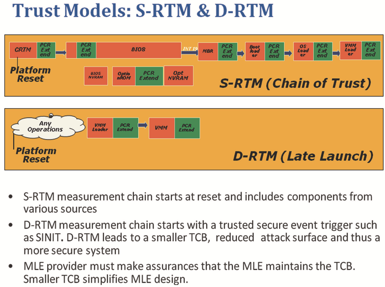
A DRTM implementation can also include a root-of-trust for verification (RTV), too. More information on Intel’s D-RTM implementation can be found in the following book by David Grawrock, Dynamics of a Trusted Platform from Intel Press.
Platform Manufacturer
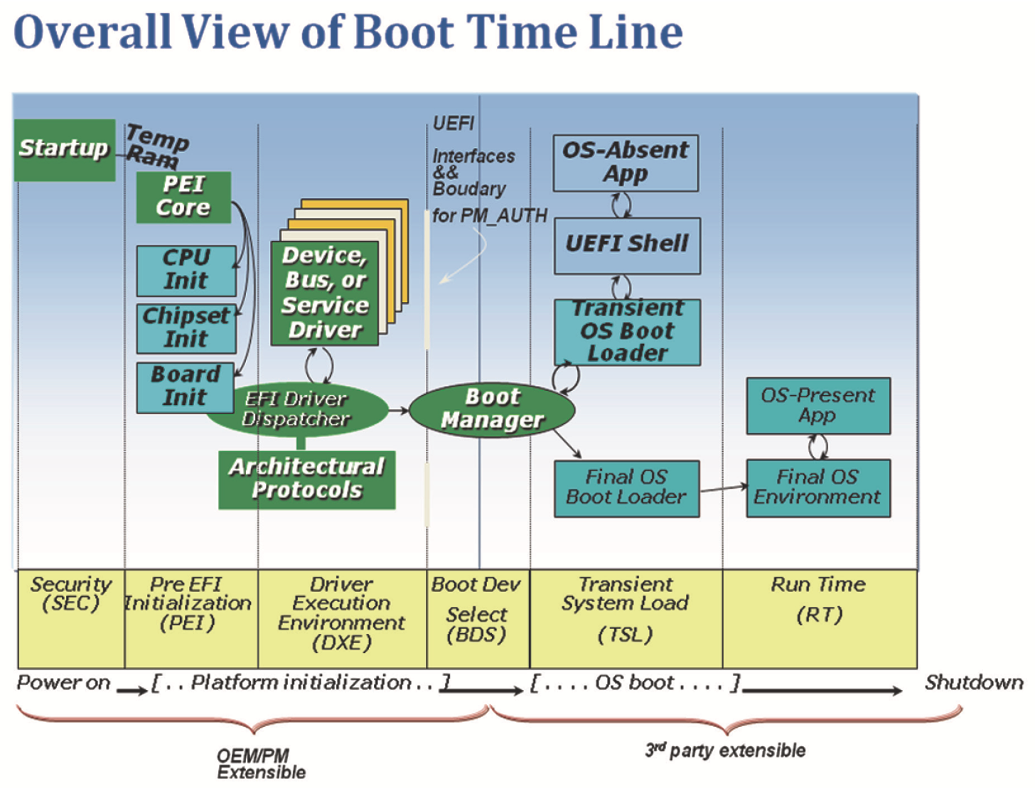
There are several terms that will be introduced in order to facilitate the following discussion. The first includes the entity that produces the final system board that includes the collection of UEFI and PI modules shown in Figure 10.23. This will be called the platform manufacturer or PM. The authority to perform updates or changes to the configuration of the UEFI and PI modules that ship from the factory are mediated by PM_AUTH or Platform Manufacturer Authority. PM_AUTH essentially describes the administrative roles that an entity who authenticates or proves itself to be the PM or delegate of the PM can perform. These actions can include but are not limited to the update of modules, firmware, or early PI settings. PM_AUTH typically is used to ensure the integrity of the PI and UEFI modules, and this integrity, or ensuring that the modules came from the manufacturer, can be accomplished via cryptographic updates of modules or signed UEFI capsules, for example.
As noted above, integrity forms one of the key security goals of the platform. If a third party can replace or impersonate a PI module without the PM’s knowledge, there is an opportunity to introduce a vulnerability into the system.
When we refer to PM_AUTH, we mean “components that are under the authority of the Platform manufacturer.” This can include provenance of the PI code and data at rest (in the system board ROM container) and also the temporal state of the code in memory during system boot and runtime. The PM_AUTH can include the PEI and DXE driver dispatch responsive to an S5 restart, the SMM code running during the operating system runtime x64, and data at rest in the ROM after field updates.
The PM_AUTH really means that we do not have arbitrary third party extensibility. Arbitrary third party code could include an operating system loader deposited on the EFI System Partition during a post-ship OS install or upgrade, a PC/AT option ROM from a host bus adapter plugged into a system.
So for this model of integrity analysis, PM_AUTH = {SEC, PEI Core, PEIMs, DXE core, DXE drivers, firmware volumes, UEFI variables used only by PEI + DXE, BDS, PMI, SMM, UEFI runtime, ACPI tables, SMBIOS tables}.
Non-PM_AUTH is non-signed UEFI drivers from a host-bus adapter (HBA), nonsigned UEFI OS loaders.
Vulnerability Classification
There are several terms that will be introduced in this section. These include spoofing, tampering, repudiation, information disclosure, denial of service, and elevation of privilege.
In order to talk about platform security, some terms will be introduced. Specifically, a vulnerability in a software or firmware product can subject the computer on which it is running to various attacks. Attacks may be grouped in the following categories:
![]() Spoofing. An attacker pretends that he is someone else, perhaps in order to inflict some damage on the person or organization impersonated.
Spoofing. An attacker pretends that he is someone else, perhaps in order to inflict some damage on the person or organization impersonated.
![]() Tampering. An attacker is able to modify data or program behavior.
Tampering. An attacker is able to modify data or program behavior.
![]() Repudiation. An attacker, who has previously taken some action, is able to deny that he took it.
Repudiation. An attacker, who has previously taken some action, is able to deny that he took it.
![]() Information Disclosure. An attacker is able to obtain access to information that he is not allowed to have.
Information Disclosure. An attacker is able to obtain access to information that he is not allowed to have.
![]() Denial of Service. An attacker prevents the system attacked from providing services to its legitimate users. The victim may become bogged down in fake workload, or even shut down completely.
Denial of Service. An attacker prevents the system attacked from providing services to its legitimate users. The victim may become bogged down in fake workload, or even shut down completely.
![]() Elevation of Privilege. An attacker, who has entered the system at a low privilege level (such as a user), acquires higher privileges (such as those of an administrator).
Elevation of Privilege. An attacker, who has entered the system at a low privilege level (such as a user), acquires higher privileges (such as those of an administrator).
Roots of Trust/ Guards
When discussing integrity, a more formal model helps define some of the terms. A popular commercial integrity model includes that defined by Clark-Wilson (CW). In the CW model, there are controlled data items (CDIs) and uncontrolled data items (UDIs). The former must have some administrative control for changes, whereas the latter do not.
An example of a UDI can include a UEFI variable like the language code, whereas a CDI can include authenticated variables such as the signature data base used for managing the x509V3 certificates. Figure 10.24 shows an example of a CDI, such as UEFI variables, and the Guard. Typically the caller would be a UEFI or OS application, the “request” would be the “set variable,” the Guard would be the UEFI implementation of the variable services, and the variable itself could include the EFI_VARIA-BLE_AUTHENTICATED_WRITE_ACCESS bit set.

Summary
This chapter has reviewed the static root of trust for measurement, or trusted boot, and the associated trusted computing hardware, including the TPM. It then described other preventive security technology, such as UEFI secure boot.
This chapter then described some background and guidance on how to prepare and integrate components that meet the platform assurance goals and also realize the purported capabilities of the security and trusted computing elements. This includes the concepts of trust and security. It also reviewed trusted computing technology, such as the Trusted Platform Module, SRTM, CRTM, and the TBB. Finally, the technology in the UEFI 2.6 specification for security, such as driver signing, network authentication, and user identification was treated.