
Chapter 9 – Some Common UEFI and PI Functions
Never let the future disturb you. You will meet it, if you have to, with the same weapons of reason which today arm you against the present.
—Marcus Aurelius Antoninus
UEFI provides a variety of functions that are used for drivers and applications to communication with the underlying UEFI components. Many of the designs for interfaces have historically been short-sighted due to their inability to predict changes in technology. An example of such shortsightedness might be where a disk interface assumed that a disk might never have more than 8 gigabytes of space available. It is often hard to predict what changes technology might provide. Many famous statements have been made that fret about how a personal computer might never be practical, or assure readers that 640 kilobytes of memory would be more than anyone would ever need. With these poor past predictions in mind, one can attempt to learn from such mistakes and design interfaces that are robust enough for common practices today, and make the best attempt at predicting how one might use these interfaces years from today.
This chapter describes a selection of common interfaces that show up in UEFI as well as the PI specifications:
![]() Architectural Protocols: These are a set of protocols that abstract the platform hardware from the UEFI drivers and applications. They are unusual only in that they are the protocols that are going to be used by the UEFI compatible firmware implementation. These protocols in their current form were introduced into the PI specifications.
Architectural Protocols: These are a set of protocols that abstract the platform hardware from the UEFI drivers and applications. They are unusual only in that they are the protocols that are going to be used by the UEFI compatible firmware implementation. These protocols in their current form were introduced into the PI specifications.
![]() PCI Protocols: These protocols abstract all aspects of interaction with the underlying PCI bus, enumeration of said bus, as well as resource allocation. These interfaces were introduced for UEFI, and would be present in both UEFI and PI implementations.
PCI Protocols: These protocols abstract all aspects of interaction with the underlying PCI bus, enumeration of said bus, as well as resource allocation. These interfaces were introduced for UEFI, and would be present in both UEFI and PI implementations.
![]() Block I/O: This protocol is used to abstract mass storage devices to allow code running in the EFI Boot Services environment to access them without specific knowledge of the type of device or controller that manages the device. This interface was introduced for UEFI, and would be present in both UEFI and PI implementations.
Block I/O: This protocol is used to abstract mass storage devices to allow code running in the EFI Boot Services environment to access them without specific knowledge of the type of device or controller that manages the device. This interface was introduced for UEFI, and would be present in both UEFI and PI implementations.
![]() Disk I/O: This protocol is used to abstract the block accesses of the Block I/O protocol to a more general offset-length protocol. The firmware is responsible for adding this protocol to any Block I/O interface that appears in the system that does not already have a Disk I/O protocol. File systems and other disk access code utilize the Disk I/O protocol. This interface was introduced for UEFI, and would be present in both UEFI and PI implementations.
Disk I/O: This protocol is used to abstract the block accesses of the Block I/O protocol to a more general offset-length protocol. The firmware is responsible for adding this protocol to any Block I/O interface that appears in the system that does not already have a Disk I/O protocol. File systems and other disk access code utilize the Disk I/O protocol. This interface was introduced for UEFI, and would be present in both UEFI and PI implementations.
![]() Simple File System: This protocol allows code running in the EFI Boot Services environment to obtain file-based access to a device. The Simple File System protocol is used to open a device volume and return an EFI_FILE handle that provides interfaces to access files on a device volume. This interface was introduced for UEFI, and would be present in both UEFI and PI implementations.
Simple File System: This protocol allows code running in the EFI Boot Services environment to obtain file-based access to a device. The Simple File System protocol is used to open a device volume and return an EFI_FILE handle that provides interfaces to access files on a device volume. This interface was introduced for UEFI, and would be present in both UEFI and PI implementations.
Architectural Protocol Examples
A variety of architectural protocols exist in the platform. These protocols function just like other protocols in every way. The only difference is that these protocols are consumed by the platform’s core services and the remainder of the drivers and applications in turn call these core services to act on the platform in various ways. Generally, the only users of the architectural protocols are the core services themselves. The architectural protocols abstract the hardware and are the only agents in the system that would typically talk directly to the hardware in the pre-boot environment. Everything else in the system would communicate with a core service to communicate any sort of requests to the hardware. Figure 9.1 illustrates this high-level software handshake.

To show more clearly how some of these architectural protocols are designed and how they operate, several key examples will be examined in further detail. Note that the following examples are not the full set of architectural protocols but are used to illustrate some of their functionality. For the full set, please refer to the appropriate DXE specifications.
CPU Architectural Protocol
The CPU Architectural Protocol is used to abstract processor-specific functions from the DXE Foundation. This includes flushing caches, enabling and disabling interrupts, hooking interrupt vectors and exception vectors, reading internal processor timers, resetting the processor, and determining the processor frequency. This protocol must be produced by a boot service or runtime DXE driver and may only be consumed by the DXE Foundation and DXE drivers that produce architectural protocols. By allowing this protocol to be produced by a boot service driver, it is evident that this abstraction will not persist when the platform has the boot services terminated by launching a boot target such as an operating system.
The GCD memory space map is initialized by the DXE Foundation based on the contents of the HOB list. The HOB list contains the capabilities of the different memory regions, but it does not contain their current attributes. The DXE driver that produces the CPU Architectural Protocol is responsible for maintaining the current attributes of the memory regions visible to the processor.
This means that the DXE driver that produces the CPU Architectural Protocol must seed the GCD memory space map with the initial state of the attributes for all the memory regions visible to the processor. The DXE Service SetMemorySpaceAttributes() allows the attributes of a memory range to be modified. The Set-MemorySpaceAttributes() DXE Service is implemented using the SetMemoryAttributes() service of the CPU Architectural Protocol.
To initialize the state of the attributes in the GCD memory space map, the DXE driver that produces the CPU Architectural Protocol must call the DXE Service Set-MemorySpaceAttributes() for all the different memory regions visible to the processor passing in the current attributes. This, in turn, will call back to the SetMemoryAttributes() service of the CPU Architectural Protocol, and all of these calls must return EFI_SUCCESS, since the DXE Foundation is only requesting that the attributes of the memory region be set to their current settings. This forces the current attributes in the GCD memory space map to be set to these current settings. After this initialization is complete, the next call to the DXE Service GetMemorySpaceMap() will correctly show the current attributes of all the memory regions. In addition, any future calls to the DXE Service SetMemorySpaceAttributes() will in turn call the CPU Architectural Protocol to see if those attributes can be modified, and if they can, the GCD memory space map will be updated accordingly.
The CPU Architectural Protocol uses the following protocol definition:

![]() FlushDataCache - Flushes a range of the processor’s data cache. If the processor does not contain a data cache, or the data cache is fully coherent, then this function can just return EFI_SUCCESS. If the processor does not support flushing a range of addresses from the data cache, then the entire data cache must be flushed. This function is used by the root bridge I/O abstractions to flush data caches for DMA operations.
FlushDataCache - Flushes a range of the processor’s data cache. If the processor does not contain a data cache, or the data cache is fully coherent, then this function can just return EFI_SUCCESS. If the processor does not support flushing a range of addresses from the data cache, then the entire data cache must be flushed. This function is used by the root bridge I/O abstractions to flush data caches for DMA operations.
![]() EnableInterrupt - Enables interrupt processing by the processor. See the Enable-Interrupt() function description. This function is used by the Boot Service RaiseTPL() and RestoreTPL().
EnableInterrupt - Enables interrupt processing by the processor. See the Enable-Interrupt() function description. This function is used by the Boot Service RaiseTPL() and RestoreTPL().
![]() DisableInterrupt - Disables interrupt processing by the processor. See the Disable-Interrupt() function description. This function is used by the Boot Service RaiseTPL() andRestoreTPL().
DisableInterrupt - Disables interrupt processing by the processor. See the Disable-Interrupt() function description. This function is used by the Boot Service RaiseTPL() andRestoreTPL().
![]() GetInterruptState - Retrieves the processor’s current interrupt state.
GetInterruptState - Retrieves the processor’s current interrupt state.
![]() Init - Generates an INIT on the processor. This function may be used by the Reset Architectural Protocol depending upon a specified boot path. If a processor cannot programmatically generate an INIT without help from external hardware, then this function returns EFI_UNSUPPORTED.
Init - Generates an INIT on the processor. This function may be used by the Reset Architectural Protocol depending upon a specified boot path. If a processor cannot programmatically generate an INIT without help from external hardware, then this function returns EFI_UNSUPPORTED.
![]() RegisterInterruptHandler - Associates an interrupt service routine with one of the processor’s interrupt vectors. This function is typically used by the EFI_TIMER_ARCH_PROTOCOL to hook the timer interrupt in a system. It can also be used by the debugger to hook exception vectors.
RegisterInterruptHandler - Associates an interrupt service routine with one of the processor’s interrupt vectors. This function is typically used by the EFI_TIMER_ARCH_PROTOCOL to hook the timer interrupt in a system. It can also be used by the debugger to hook exception vectors.
![]() GetTimerValue - Returns the value of one of the processor’s internal timers.
GetTimerValue - Returns the value of one of the processor’s internal timers.
![]() SetMemoryAttributes - Attempts to set the attributes of a memory region.
SetMemoryAttributes - Attempts to set the attributes of a memory region.
![]() NumberOfTimers – Gives the number of timers that are available in a processor. The value in this field is a constant that must not be modified after the CPU Architectural Protocol is installed. All consumers must treat this as a read-only field.
NumberOfTimers – Gives the number of timers that are available in a processor. The value in this field is a constant that must not be modified after the CPU Architectural Protocol is installed. All consumers must treat this as a read-only field.
![]() DmaBufferAlignment – Gives the size, in bytes, of the alignment required for DMA buffer allocations. This is typically the size of the largest data cache line in the platform. This value can be determined by looking at the data cache line sizes of all the caches present in the platform, and returning the largest. This is used by the root bridge I/O abstraction protocols to guarantee that no two DMA buffers ever share the same cache line. The value in this field is a constant that must not be modified after the CPU Architectural Protocol is installed. All consumers must treat this as a read-only field.
DmaBufferAlignment – Gives the size, in bytes, of the alignment required for DMA buffer allocations. This is typically the size of the largest data cache line in the platform. This value can be determined by looking at the data cache line sizes of all the caches present in the platform, and returning the largest. This is used by the root bridge I/O abstraction protocols to guarantee that no two DMA buffers ever share the same cache line. The value in this field is a constant that must not be modified after the CPU Architectural Protocol is installed. All consumers must treat this as a read-only field.
Real Time Clock Architectural Protocol
The Real Time Clock Architectural Protocol provides the services required to access a system’s real time clock hardware. This protocol must be produced by a runtime DXE driver and may only be consumed by the DXE Foundation.
The DXE driver that produces this protocol must be a runtime driver. This driver is responsible for initializing the GetTime(), SetTime(), GetWakeupTime(), and SetWakeupTime() fields of the EFI Runtime Services Table. See the section “Time Services” in Chapter 5 for details on these services. After the four fields of the EFI Runtime Services Table have been initialized, the driver must install the Real Time Clock Architectural Protocol on a new handle with a NULL interface pointer. The installation of this protocol informs the DXE Foundation that the real time clock-related services are now available and that the DXE Foundation must update the 32-bit CRC of the EFI Runtime Services Table.
Timer Architectural Protocol
The Timer Architectural Protocol provides the services to initialize a periodic timer interrupt and to register a handler that is called each time the timer interrupt fires. It may also provide a service to adjust the rate of the periodic timer interrupt. When a timer interrupt occurs, the handler is passed the amount of time that has passed since the previous timer interrupt. This protocol enables the use of the SetTimer() Boot Service. This protocol must be produced by a boot service or runtime DXE driver and may only be consumed by the DXE Foundation or DXE drivers that produce other DXE Architectural Protocols. By allowing this protocol to be produced by a boot service driver, it is evident that this abstraction will not persist when the platform has the boot services terminated by launching a boot target, such as an operating system.

![]() RegisterHandler - Registers a handler that is called each time the timer interrupt fires. TimerPeriod defines the minimum time between timer interrupts, so TimerPeriod is also the minimum time between calls to the registered handler.
RegisterHandler - Registers a handler that is called each time the timer interrupt fires. TimerPeriod defines the minimum time between timer interrupts, so TimerPeriod is also the minimum time between calls to the registered handler.
![]() SetTimerPeriod - Sets the period of the timer interrupt in 100 nanosecond units. This function is optional and may return EFI_UNSUPPORTED. If this function is supported, then the timer period is rounded up to the nearest supported timer period.
SetTimerPeriod - Sets the period of the timer interrupt in 100 nanosecond units. This function is optional and may return EFI_UNSUPPORTED. If this function is supported, then the timer period is rounded up to the nearest supported timer period.
![]() GetTimerPeriod - Retrieves the period of the timer interrupt in 100 nanosecond units.
GetTimerPeriod - Retrieves the period of the timer interrupt in 100 nanosecond units.
![]() GenerateSoftInterrupt - Generates a soft timer interrupt that simulates the firing of the timer interrupt. This service can be used to invoke the registered handler if the timer interrupt has been masked for a period of time.
GenerateSoftInterrupt - Generates a soft timer interrupt that simulates the firing of the timer interrupt. This service can be used to invoke the registered handler if the timer interrupt has been masked for a period of time.
Reset Architectural Protocol
The Reset Architectural Protocol provides the service required to reset a platform. This protocol must be produced by a runtime DXE driver and may only be consumed by the DXE Foundation. This driver is responsible for initializing the ResetSystem() field of the EFI Runtime Services Table. After this field of the EFI Runtime Services Table has been initialized, the driver must install the Reset Architectural Protocol on a new handle with a NULL interface pointer. The installation of this protocol informs the DXE Foundation that the reset system service is now available and that the DXE Foundation must update the 32-bit CRC of the EFI Runtime Services Table.
Boot Device Selection Architectural Protocol
The Boot Device Selection (BDS) Architectural Protocol transfers control from DXE to an operating system or a system utility, as illustrated in Figure 9.2. This protocol must be produced by a boot service or runtime DXE driver and may only be consumed by the DXE Foundation. By allowing this protocol to be produced by a boot service driver, it is evident that this abstraction will not persist when the platform has the boot services terminated by launching a boot target such as an operating system.
If not enough drivers have been initialized when this protocol is used to access the required boot device(s), then this protocol should add drivers to the dispatch queue and return control back to the dispatcher. Once the required boot devices are available, then the boot device can be used to load and invoke an OS or a system utility.


![]() Entry - The entry point to BDS. See the Entry() function description. This call does not take any parameters, and the return value can be ignored. If it returns, then the dispatcher must be invoked again, if it never returns, then an operating system or a system utility have been invoked.
Entry - The entry point to BDS. See the Entry() function description. This call does not take any parameters, and the return value can be ignored. If it returns, then the dispatcher must be invoked again, if it never returns, then an operating system or a system utility have been invoked.
Variable Architectural Protocol
The Variable Architectural Protocol provides the services required to get and set environment variables. This protocol must be produced by a runtime DXE driver and may be consumed only by the DXE Foundation. This driver is responsible for initializing the GetVariable(), GetNextVariableName(), and SetVariable() fields of the EFI Runtime Services Table. See the section “Variable Services” in Chapter 5 for details on these services. After the three fields of the EFI Runtime Services Table have been initialized, the driver must install the Variable Architectural Protocol on a new handle with a NULL interface pointer. The installation of this protocol informs the DXE Foundation that the read-only and the volatile environment variable related services are now available and that the DXE Foundation must update the 32-bit CRC of the EFI Runtime Services Table. The full complement of environment variable services is not available until both this protocol and Variable Write Architectural Protocol are installed. DXE drivers that require read-only access or read/write access to volatile environment variables must have this architectural protocol in their dependency expressions. DXE drivers that require write access to nonvolatile environment variables must have the Variable Write Architectural Protocol in their dependency expressions.
Watchdog Timer Architectural Protocol
The Watchdog Timer Architectural Protocol is used to program the watchdog timer and optionally register a handler when the watchdog timer fires. This protocol must be produced by a boot service or runtime DXE driver and may be consumed only by the DXE Foundation or DXE drivers that produce other DXE Architectural Protocols. If a platform wishes to perform a platform-specific action when the watchdog timer expires, then the DXE driver containing the implementation of the BDS Architectural Protocol should use this protocol's RegisterHandler() service.
This protocol provides the services required to implement the Boot Service SetWatchdogTimer(). It provides a service to set the amount of time to wait before firing the watchdog timer, and it also provides a service to register a handler that is invoked when the watchdog timer fires. This protocol can implement the watchdog timer by using the event and timer Boot Services, or it can make use of custom hardware. When the watchdog timer fires, control will be passed to a handler if a handler has been registered. If no handler has been registered, or the registered handler returns, then the system will be reset by calling the Runtime Service ResetSystem().

![]() RegisterHandler - Registers a handler that is invoked when the watchdog timer fires.
RegisterHandler - Registers a handler that is invoked when the watchdog timer fires.
![]() SetTimerPeriod - Sets the amount of time in 100 nanosecond units to wait before the watchdog timer is fired. If this function is supported, then the watchdog timer period is rounded up to the nearest supported watchdog timer period.
SetTimerPeriod - Sets the amount of time in 100 nanosecond units to wait before the watchdog timer is fired. If this function is supported, then the watchdog timer period is rounded up to the nearest supported watchdog timer period.
![]() GetTimerPeriod - Retrieves the amount of time in 100 nanosecond units that the system will wait before the watchdog timer is fired.
GetTimerPeriod - Retrieves the amount of time in 100 nanosecond units that the system will wait before the watchdog timer is fired.
PCI Protocols
This section describes a series of protocols that are all related to abstracting various aspects of PCI related interaction such as resource allocation and I/O.
PCI Host Bridge Resource Allocation Protocol
The PCI Host Bridge Resource Allocation Protocol is used by a PCI bus driver to program a PCI host bridge. The registers inside a PCI host bridge that control configuration of PCI root buses are not governed by the PCI specification and vary from chipset to chipset. The PCI Host Bridge Resource Allocation Protocol implementation is therefore specific to a particular chipset.
Each PCI host bridge is composed of one or more PCI root bridges, and hardware registers are associated with each PCI root bridge. These registers control the bus, I/O, and memory resources that are decoded by the PCI root bus that the PCI root bridge produces and all the PCI buses that are children of that PCI root bus.
The PCI Host Bridge Resource Allocate Protocol allows for future innovation of the chipsets. It abstracts the PCI bus driver from the chipset details. This design allows system designers to make changes to the host bridge hardware without impacting a platform independent PCI bus driver.
Figure 9.3 shows a platform with a set of processors (CPUs) and a set of core chipset components that produce n host bridges. Most systems with one PCI host bus controller contain a single instance of the PCI Host Bridge Allocation Protocol. More complex systems may contain multiple instances of this protocol.

Figure 9.4 shows how the PCI Host Bridge Resource Allocation Protocol is used to identify the associated PCI root bridges. After the steps shown in Figure 9.4 are completed, the PCI Host Bridge Resource Allocation Protocol can then be queried to identify the device handles of the associated PCI root bridges.

Sample Desktop System with One PCI Root Bridge
Figure 9.5 shows an example of a PCI host bus with one PCI root bridge. This PCI root bridge produces one PCI local bus that can contain PCI devices on the motherboard and/ or PCI slots. This setup would be typical of a desktop system. In this system, the PCI root bridge needs minimal setup. Typically, the PCI root bridge decodes the following:
![]() The entire bus range on Segment 0
The entire bus range on Segment 0
![]() The entire I/ O space of the processor
The entire I/ O space of the processor
![]() All the memory above the top of system memory
All the memory above the top of system memory
The firmware for this platform would produce the following:
![]() One instance of the PCI Host Bridge Resource Allocation Protocol
One instance of the PCI Host Bridge Resource Allocation Protocol
![]() One instance of PCI Root Bridge I/O Protocol
One instance of PCI Root Bridge I/O Protocol

Sample Server System with Four PCI Root Bridges
Figure 9.6 shows an example of a larger server with one PCI host Bus with four PCI root bridges (RBs). The PCI devices that are attached to the PCI root bridges are all part of the same coherency domain, which means they share the following:
![]() A common PCI I/O space
A common PCI I/O space
![]() A common PCI memory space
A common PCI memory space
![]() A common PCI pre-fetchable memory space
A common PCI pre-fetchable memory space
As a result, each PCI root bridge must get resources out of a common pool. Each PCI root bridge produces one PCI local bus that can contain PCI devices on the motherboard or PCI slots. The firmware for this platform would produce the following:
![]() One instance of the PCI Host Bridge Resource Allocation Protocol
One instance of the PCI Host Bridge Resource Allocation Protocol
![]() Four instances of the PCI Root Bridge I/ O Protocol
Four instances of the PCI Root Bridge I/ O Protocol

Sample Server System with 2 PCI Segments
Figure 9.7 shows an example of a server with one PCI host bus and two PCI root bridges (RBs). Each of these PCI root bridges is on a different PCI segment, which allows the system to have up to 512 PCI buses. A single PCI segment is limited to 256 PCI buses. These two segments do not share the same PCI configuration space, but they do share the following, which is why they can be described with a single PCI host bus:
![]() A common PCI I/O space
A common PCI I/O space
![]() A common PCI memory space
A common PCI memory space
![]() A common PCI pre-fetchable memory space
A common PCI pre-fetchable memory space
The firmware for this platform would produce the following:
![]() One instance of the PCI Host Bridge Resource Allocation Protocol
One instance of the PCI Host Bridge Resource Allocation Protocol
![]() Two instances of the PCI Root Bridge I/O Protocol
Two instances of the PCI Root Bridge I/O Protocol


Figure 9.8 shows a server system with two PCI host buses and one PCI root bridge (RB) per PCI host bus. Like the server system with 2 PCI segments, this system supports up to 512 PCI buses, but the following resources are not shared between the two PCI root bridges:
![]() PCI I/O space
PCI I/O space
![]() PCI memory space
PCI memory space
![]() PCI pre-fetchable memory space
PCI pre-fetchable memory space
The firmware for this platform would produce the following:
![]() Two instances of the PCI Host Bridge Resource Allocation Protocol
Two instances of the PCI Host Bridge Resource Allocation Protocol
![]() Two instances of the PCI Root Bridge I/O Protocol
Two instances of the PCI Root Bridge I/O Protocol
PCI Root Bridge I/O
The interfaces provided in the PCI Root Bridge I/O Protocol are for performing basic operations to memory, I/O, and PCI configuration space. The system provides abstracted access to basic system resources to allow a driver to have a programmatic method to access these basic system resources.
The PCI Root Bridge I/O Protocol allows for future innovation of the platform. It abstracts device-specific code from the system memory map. This allows system designers to make changes to the system memory map without impacting platform-independent code that is consuming basic system resources.
PCI Root Bridge I/O Protocol instances are either produced by the system firmware or by an UEFI driver. When a PCI Root Bridge I/O Protocol is produced, it is placed on a device handle along with an EFI Device Path Protocol instance. The PCI Root Bridge I/O Protocol does not abstract access to the chipset-specific registers that are used to manage a PCI Root Bridge. This functionality is hidden within the system firmware or the UEFI driver that produces the handles that represent the PCI Root Bridges.

![]() ParentHandle – Gives the EFI_HANDLE of the PCI Host Bridge of which this PCI Root Bridge is a member.
ParentHandle – Gives the EFI_HANDLE of the PCI Host Bridge of which this PCI Root Bridge is a member.
![]() PollMem - Polls an address in memory mapped I/O space until an exit condition is met, or a timeout occurs.
PollMem - Polls an address in memory mapped I/O space until an exit condition is met, or a timeout occurs.
![]() PollIo - Polls an address in I/O space until an exit condition is met, or a timeout occurs.
PollIo - Polls an address in I/O space until an exit condition is met, or a timeout occurs.
![]() Mem - Allows reads and writes for memory mapped I/O space.
Mem - Allows reads and writes for memory mapped I/O space.
![]() Io - Allows reads and writes for I/O space.
Io - Allows reads and writes for I/O space.
![]() Pci - Allows reads and writes for PCI configuration space.
Pci - Allows reads and writes for PCI configuration space.
![]() CopyMem - Allows one region of PCI root bridge memory space to be copied to another region of PCI root bridge memory space.
CopyMem - Allows one region of PCI root bridge memory space to be copied to another region of PCI root bridge memory space.
![]() Map - Provides the PCI controller–specific addresses needed to access system memory for DMA.
Map - Provides the PCI controller–specific addresses needed to access system memory for DMA.
![]() Unmap - Releases any resources allocated by Map().
Unmap - Releases any resources allocated by Map().
![]() AllocateBuffer - Allocates pages that are suitable for a common buffer mapping.
AllocateBuffer - Allocates pages that are suitable for a common buffer mapping.
![]() FreeBuffer – Frees pages that were allocated with AllocateBuffer().
FreeBuffer – Frees pages that were allocated with AllocateBuffer().
![]() Flush - Flushes all PCI posted write transactions to system memory.
Flush - Flushes all PCI posted write transactions to system memory.
![]() GetAttributes - Gets the attributes that a PCI root bridge supports setting with SetAttributes(), and the attributes that a PCI root bridge is currently using.
GetAttributes - Gets the attributes that a PCI root bridge supports setting with SetAttributes(), and the attributes that a PCI root bridge is currently using.
![]() SetAttributes - Sets attributes for a resource range on a PCI root bridge.
SetAttributes - Sets attributes for a resource range on a PCI root bridge.
![]() Configuration - Gets the current resource settings for this PCI root bridge.
Configuration - Gets the current resource settings for this PCI root bridge.
![]() SegmentNumber - The segment number that this PCI root bridge resides.
SegmentNumber - The segment number that this PCI root bridge resides.
PCI I/O
The interfaces provided in the PCI I/O Protocol are for performing basic operations to memory, I/O, and PCI configuration space. The system provides abstracted access to basic system resources to allow a driver to have a programmatic method to access these basic system resources. The main goal of this protocol is to provide an abstraction that simplifies the writing of device drivers for PCI devices. This goal is accomplished by providing the following features:
![]() A driver model that does not require the driver to search the PCI busses for devices to manage. Instead, drivers are provided the location of the device to manage or have the capability to be notified when a PCI controller is discovered.
A driver model that does not require the driver to search the PCI busses for devices to manage. Instead, drivers are provided the location of the device to manage or have the capability to be notified when a PCI controller is discovered.
![]() A device driver model that abstracts the I/O addresses, Memory addresses, and PCI Configuration addresses from the PCI device driver. Instead, BAR (Base Address Register) relative addressing is used for I/O and Memory accesses, and device relative addressing is used for PCI Configuration accesses. The BAR relative addressing is specified in the PCI I/O services as a BAR index. A PCI controller may contain a combination of 32-bit and 64-bit BARs. The BAR index represents the logical BAR number in the standard PCI configuration header starting from the first BAR. The BAR index does not represent an offset into the standard PCI Configuration Header because those offsets will vary depending on the combination and order of 32-bit and 64-bit BARs.
A device driver model that abstracts the I/O addresses, Memory addresses, and PCI Configuration addresses from the PCI device driver. Instead, BAR (Base Address Register) relative addressing is used for I/O and Memory accesses, and device relative addressing is used for PCI Configuration accesses. The BAR relative addressing is specified in the PCI I/O services as a BAR index. A PCI controller may contain a combination of 32-bit and 64-bit BARs. The BAR index represents the logical BAR number in the standard PCI configuration header starting from the first BAR. The BAR index does not represent an offset into the standard PCI Configuration Header because those offsets will vary depending on the combination and order of 32-bit and 64-bit BARs.
![]() The Device Path for the PCI device can be obtained from the same device handle that the PCI I/O Protocol resides.
The Device Path for the PCI device can be obtained from the same device handle that the PCI I/O Protocol resides.
![]() The PCI Segment, PCI Bus Number, PCI Device Number, and PCI Function Number of the PCI device if they are required. The general idea is to abstract these details away from the PCI device driver. However, if these details are required, then they are available.
The PCI Segment, PCI Bus Number, PCI Device Number, and PCI Function Number of the PCI device if they are required. The general idea is to abstract these details away from the PCI device driver. However, if these details are required, then they are available.
![]() Details on any nonstandard address decoding that are not covered by the PCI device’s Base Address Registers.
Details on any nonstandard address decoding that are not covered by the PCI device’s Base Address Registers.
![]() Access to the PCI Root Bridge I/O Protocol for the PCI Host Bus for which the PCI device is a member.
Access to the PCI Root Bridge I/O Protocol for the PCI Host Bus for which the PCI device is a member.
![]() A copy of the PCI Option ROM if it is present in system memory.
A copy of the PCI Option ROM if it is present in system memory.
![]() Functions to perform bus mastering DMA. This includes both packet based DMA and common buffer DMA.
Functions to perform bus mastering DMA. This includes both packet based DMA and common buffer DMA.

![]() PollMem - Polls an address in PCI memory space until an exit condition is met, or a timeout occurs.
PollMem - Polls an address in PCI memory space until an exit condition is met, or a timeout occurs.
![]() PollIo - Polls an address in PCI I/O space until an exit condition is met, or a timeout occurs.
PollIo - Polls an address in PCI I/O space until an exit condition is met, or a timeout occurs.
![]() Mem - Allows BAR relative reads and writes for PCI memory space.
Mem - Allows BAR relative reads and writes for PCI memory space.
![]() Io - Allows BAR relative reads and writes for PCI I/O space.
Io - Allows BAR relative reads and writes for PCI I/O space.
![]() Pci - Allows PCI controller relative reads and writes for PCI configuration space.
Pci - Allows PCI controller relative reads and writes for PCI configuration space.
![]() CopyMem - Allows one region of PCI memory space to be copied to another region of PCI memory space.
CopyMem - Allows one region of PCI memory space to be copied to another region of PCI memory space.
![]() Map - Provides the PCI controller–specific address needed to access system memory for DMA.
Map - Provides the PCI controller–specific address needed to access system memory for DMA.
![]() Unmap - Releases any resources allocated by Map().
Unmap - Releases any resources allocated by Map().
![]() AllocateBuffer - Allocates pages that are suitable for a common buffer mapping.
AllocateBuffer - Allocates pages that are suitable for a common buffer mapping.
![]() FreeBuffer - Frees pages that were allocated with AllocateBuffer().
FreeBuffer - Frees pages that were allocated with AllocateBuffer().
![]() Flush - Flushes all PCI posted write transactions to system memory.
Flush - Flushes all PCI posted write transactions to system memory.
![]() GetLocation - Retrieves this PCI controller’s current PCI bus number, device number, and function number.
GetLocation - Retrieves this PCI controller’s current PCI bus number, device number, and function number.
![]() Attributes - Performs an operation on the attributes that this PCI controller supports. The operations include getting the set of supported attributes, retrieving the current attributes, setting the current attributes, enabling attributes, and disabling attributes.
Attributes - Performs an operation on the attributes that this PCI controller supports. The operations include getting the set of supported attributes, retrieving the current attributes, setting the current attributes, enabling attributes, and disabling attributes.
![]() GetBarAttributes - Gets the attributes that this PCI controller supports setting on a BAR using SetBarAttributes(), and retrieves the list of resource descriptors for a BAR.
GetBarAttributes - Gets the attributes that this PCI controller supports setting on a BAR using SetBarAttributes(), and retrieves the list of resource descriptors for a BAR.
![]() SetBarAttributes - Sets the attributes for a range of a BAR on a PCI controller.
SetBarAttributes - Sets the attributes for a range of a BAR on a PCI controller.
![]() RomSize – Gives the size, in bytes, of the ROM image.
RomSize – Gives the size, in bytes, of the ROM image.
![]() RomImage – Returns a pointer to the in memory copy of the ROM image. The PCI Bus Driver is responsible for allocating memory for the ROM image, and copying the contents of the ROM to memory. The contents of this buffer are either from the PCI option ROM that can be accessed through the ROM BAR of the PCI controller, or from a platform-specific location. The Attributes() function can be used to determine from which of these two sources the RomImage buffer was initialized.
RomImage – Returns a pointer to the in memory copy of the ROM image. The PCI Bus Driver is responsible for allocating memory for the ROM image, and copying the contents of the ROM to memory. The contents of this buffer are either from the PCI option ROM that can be accessed through the ROM BAR of the PCI controller, or from a platform-specific location. The Attributes() function can be used to determine from which of these two sources the RomImage buffer was initialized.
Block I/O
The Block I/O Protocol is used to abstract mass storage devices to allow code running in the UEFI boot services environment to access them without specific knowledge of the type of device or controller that manages the device. Functions are defined to read and write data at a block level from mass storage devices as well as to manage such devices in the UEFI boot services environment.
The Block interface constructs a logical abstraction of the storage device. Figure 9.9 shows how a typical device that has multiple partitions will have a variety of Block interfaces constructed on it. For example, a partition that is a logical designation of how a disk might be apportioned will have a block interface for it. It should be noted that a particular storage device will have a block interface that has a scope that spans the entire storage device, and the logical partitions will have a scope that is a subset of the device. For instance, in the example shown in Figure 9.8, Block I/ O #1 has access to the entire disk, while Block I/ O #2 has its first LBA starting at the physical location of the partition it is associated with.


–Revision - The revision to which the block IO interface adheres. All future revisions must be backward compatible. If a future version is not backward compatible it is not the same GUID.
–Media - A pointer to the EFI_BLOCK_IO_MEDIA data for this device. Type EFI_BLOCK_IO_MEDIA is defined in the next code sample.
–Reset - Resets the block device hardware.
–ReadBlocks - Reads the requested number of blocks from the device.
–WriteBlocks - Writes the requested number of blocks to the device.
–FlushBlocks - Flushes and cache blocks. This function is optional and only needs to be supported on block devices that cache writes.

Disk I/O
The Disk I/O protocol is used to abstract the block accesses of the Block I/O protocol to a more general offset-length protocol. The firmware is responsible for adding this protocol to any Block I/O interface that appears in the system that does not already have a Disk I/O protocol. File systems and other disk access code utilize the Disk I/O protocol.
The disk I/O functions allow I/O operations that need not be on the underlying device’s block boundaries or alignment requirements. This is done by copying the data to/from internal buffers as needed to provide the proper requests to the block I/O device. Outstanding write buffer data is flushed by using the Flush() function of the Block I/O protocol on the device handle.
The firmware automatically adds a Disk I/O interface to any Block I/O interface that is produced. It also adds file system, or logical block I/O, interfaces to any Disk I/O interface that contains any recognized file system or logical block I/O devices. UEFI compliant firmware must automatically support the following required formats:
![]() The UEFI FAT12, FAT16, and FAT32 file system type.
The UEFI FAT12, FAT16, and FAT32 file system type.
![]() The legacy master boot record partition block. (The presence of this on any block I/O device is optional, but if it is present the firmware is responsible for allocating a logical device for each partition).
The legacy master boot record partition block. (The presence of this on any block I/O device is optional, but if it is present the firmware is responsible for allocating a logical device for each partition).
![]() The extended partition record partition block.
The extended partition record partition block.
![]() The El Torito logical block devices.
The El Torito logical block devices.
![]() The Disk I/O interface provides a very simple interface that allows for a more general offset-length abstraction of the underlying Block I/O protocol.
The Disk I/O interface provides a very simple interface that allows for a more general offset-length abstraction of the underlying Block I/O protocol.

![]() Revision - The revision to which the disk I/O interface adheres. All future revisions must be backwards compatible. If a future version is not backwards compatible, it is not the same GUID.
Revision - The revision to which the disk I/O interface adheres. All future revisions must be backwards compatible. If a future version is not backwards compatible, it is not the same GUID.
![]() ReadDisk - Reads data from the disk.
ReadDisk - Reads data from the disk.
![]() WriteDisk - Writes data to the disk.
WriteDisk - Writes data to the disk.
Simple File System
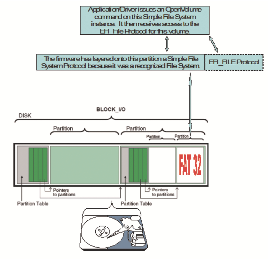
The Simple File System protocol allows code running in the UEFI boot services environment to obtain file-based access to a device. The Simple File System protocol is used to open a device volume and return an EFI File Handle that provides interfaces to access files on a device volume. This protocol is a bit different from most, since its use exposes a secondary protocol that will directly act on the device on top of which the Simple File System was layered. Figure 9.10 illustrates this concept.

![]() Revision - The version of the EFI Simple File System Protocol. The version specified by this specification is 0x00010000. All future revisions must be backward compatible. If a future version is not backward compatible, it is not the same GUID.
Revision - The version of the EFI Simple File System Protocol. The version specified by this specification is 0x00010000. All future revisions must be backward compatible. If a future version is not backward compatible, it is not the same GUID.
![]() OpenVolume - Opens the volume for file I/O access.
OpenVolume - Opens the volume for file I/O access.
EFI File Protocol
On requesting the file system protocol on a device, the caller gets the instance of the Simple File System protocol to the volume. This interface is used to open the root directory of the file system when needed. The caller must Close() the file handle to the root directory and any other opened file handles before exiting. While open files are on the device, usage of underlying device protocol(s) that the file system is abstracting must be avoided. For example, when a file system is layered on a DISK_IO / BLOCK_IO protocol, direct block access to the device for the blocks that comprise the file system must be avoided while open file handles to the same device exist.
A file system driver may cache data relating to an open file. A Flush() function is provided that flushes all dirty data in the file system, relative to the requested file, to the physical medium. If the underlying device may cache data, the file system must inform the device to flush as well.

![]() Revision - The version of the EFI_FILE interface. The version specified by this specification is 0x00010000. Future versions are required to be backward compatible to version 1.0.
Revision - The version of the EFI_FILE interface. The version specified by this specification is 0x00010000. Future versions are required to be backward compatible to version 1.0.
![]() Open - Opens or creates a new file.
Open - Opens or creates a new file.
![]() Close - Closes the current file handle.
Close - Closes the current file handle.
![]() Delete - Deletes a file.
Delete - Deletes a file.
![]() Read - Reads bytes from a file.
Read - Reads bytes from a file.
![]() Write - Writes bytes to a file.
Write - Writes bytes to a file.
![]() GetPosition - Returns the current file position.
GetPosition - Returns the current file position.
![]() SetPosition - Sets the current file position.
SetPosition - Sets the current file position.
![]() GetInfo - Gets the requested file or volume information.
GetInfo - Gets the requested file or volume information.
![]() SetInfo - Sets the requested file information.
SetInfo - Sets the requested file information.
![]() Flush - Flushes all modified data associated with the file to the device.
Flush - Flushes all modified data associated with the file to the device.
Configuration Infrastructure
The modern UEFI configuration infrastructure that was first described in the UEFI 2.1 specification is known as the Human Interface Infrastructure (HII). HII includes the following set of services:
![]() Database Services. A series of UEFI protocols that are intended to be an inmemory repository of specialized databases. These database services are focused on differing types of information:
Database Services. A series of UEFI protocols that are intended to be an inmemory repository of specialized databases. These database services are focused on differing types of information:
–Database Repository – This is the interface that drivers interact with to manipulate configuration related contents. It is most often used to register data and update keyboard layout related information.
–String Repository – This is the interface that drivers interact with to manipulate string-based data. It is most often used to extract strings associated with a given token value.
–Font Repository – The interface to which drivers may contribute font-related information for the system to use. Otherwise, it is primarily used by the underlying firmware to extract the built-in fonts to render text to the local monitor. Note that since not all platforms have inherent support for rendering fonts locally (think headless platforms), general purpose UI designs should not presume this capability.
–Image Repository – The interface to which drivers may contribute image-related information for the system to use. This is for purposes of referencing graphical items as a component of a user interface. Note that since not all platforms have inherent support for rendering images locally (think headless platforms), general purpose UI designs should not presume this capability.
![]() Browser Services. The interface that is provided by the platform’s BIOS to interact with the built-in browser. This service’s look-and-feel is implementation-specific, which allows for platform differentiation.
Browser Services. The interface that is provided by the platform’s BIOS to interact with the built-in browser. This service’s look-and-feel is implementation-specific, which allows for platform differentiation.
![]() Configuration Routing Services. The interface that manages the movement of configuration data from drivers to target configuration applications. It then serves as the single point to receive configuration information from configuration applications, routing the results to the appropriate drivers.
Configuration Routing Services. The interface that manages the movement of configuration data from drivers to target configuration applications. It then serves as the single point to receive configuration information from configuration applications, routing the results to the appropriate drivers.
![]() Configuration Access Services. The interface that is exposed by a driver’s configuration handler and is called by the configuration routing services. This service abstracts a driver’s configuration settings and also provides a means by which the platform can call the driver to initiate driver-specific operations.
Configuration Access Services. The interface that is exposed by a driver’s configuration handler and is called by the configuration routing services. This service abstracts a driver’s configuration settings and also provides a means by which the platform can call the driver to initiate driver-specific operations.
Using the Configuration Infrastructure
The overview introduced the components of the UEFI configuration infrastructure. This section discusses with a bit more detail how one goes about using aspects of this infrastructure. The following steps are initiated by a driver that is concerned with using the configuration infrastructure:
![]() Initialize hardware. The primary job of a device driver is typically to initialize the hardware that it owns. During this process of physically initializing the device, the driver is also responsible for establishing the proper configuration state information for that device. These typically include doing the following:
Initialize hardware. The primary job of a device driver is typically to initialize the hardware that it owns. During this process of physically initializing the device, the driver is also responsible for establishing the proper configuration state information for that device. These typically include doing the following:
–Installing required protocols. Protocols are interfaces that will be used to communicate with the driver. One of the more pertinent protocols associated with configuration would be the Configuration Access protocol. This is used by the system BIOS and agents in the BIOS to interact with the driver. This is also the mechanism by which a driver can provide an abstraction to a proprietary nonvolatile storage that under normal circumstances would not be usable by anyone other than the driver itself. This is how configuration data can be exposed for add-in devices and others can send configuration update requests without needing direct knowledge of that device.
–Creating an EFI device path on an EFI handle. A device path is a binary description of the device and typically how it is attached to the system. This provides a unique name for the managed device and will be used by the system to refer to the device later.
![]() Register Configuration Content. One of the latter parts of the driver initialization (once a device path has been established) is the registration of the configuration data with the underlying UEFI-compatible BIOS. The configuration data typically consists of sets of forms and strings that contain sufficient information for the platform to render pages for a user to interact with. It should also be noted that now that the configuration data is encapsulated in a binary format, what was previously an opaque meaningless set of data is now a well-known and exportable set of data that greatly expands the configurability of the device by both local and remote agents as well as BIOS and OS-present components.
Register Configuration Content. One of the latter parts of the driver initialization (once a device path has been established) is the registration of the configuration data with the underlying UEFI-compatible BIOS. The configuration data typically consists of sets of forms and strings that contain sufficient information for the platform to render pages for a user to interact with. It should also be noted that now that the configuration data is encapsulated in a binary format, what was previously an opaque meaningless set of data is now a well-known and exportable set of data that greatly expands the configurability of the device by both local and remote agents as well as BIOS and OS-present components.
![]() Respond to Configuration Event. Once the initialization and registration functions have completed, the driver could potentially remain dormant until called upon. A driver would most often be called upon to act on a configuration event. A configuration event is an event that occurs when a BIOS component calls upon one of the interfaces that the driver exposed (such as the Configuration Access protocol) and sends the driver a directive. These directives typically would be something akin to “give me your current settings” or “adjust setting X’s value to a 5”.
Respond to Configuration Event. Once the initialization and registration functions have completed, the driver could potentially remain dormant until called upon. A driver would most often be called upon to act on a configuration event. A configuration event is an event that occurs when a BIOS component calls upon one of the interfaces that the driver exposed (such as the Configuration Access protocol) and sends the driver a directive. These directives typically would be something akin to “give me your current settings” or “adjust setting X’s value to a 5”.
Much more detail on this particular infrastructure is covered later in the book.
Driver Model Interactions
The drivers that interact with the UEFI configuration infrastructure are often compliant with the UEFI driver model, as the examples shown in Figure 9.11 and Figure 9.12. Since driver model compliance is very common (and highly recommended) for device drivers, several examples are shown below that describe in detail how such a driver would most effectively leverage the configuration infrastructure.

![]() Step 1. During driver initialization, install services on the controller handle.
Step 1. During driver initialization, install services on the controller handle.
![]() Step 2. During driver initialization, discover the managed device. Create a device handle and then install various services on it.
Step 2. During driver initialization, discover the managed device. Create a device handle and then install various services on it.
![]() Step 3. During driver initialization, configuration data for the device is registered with the HII database (through the NewPackageList() API) using the device’s device handle. A unique HII handle is created during the registration event.
Step 3. During driver initialization, configuration data for the device is registered with the HII database (through the NewPackageList() API) using the device’s device handle. A unique HII handle is created during the registration event.
![]() Step 4. During system operation, when a configuration event occurs, the system addresses (through the Configuration Access protocol) the configuration services associated with the device.
Step 4. During system operation, when a configuration event occurs, the system addresses (through the Configuration Access protocol) the configuration services associated with the device.

![]() Step 1. During driver initialization, install services on the controller handle.
Step 1. During driver initialization, install services on the controller handle.
![]() Step 2. During driver initialization, discover the managed device(s). Create device handle(s) and then install various services on them.
Step 2. During driver initialization, discover the managed device(s). Create device handle(s) and then install various services on them.
![]() Step 3. During driver initialization, configuration data for each device is registered with the HII database (through the NewPackageList() API) using each device’s device handle. A unique HII handle is created during the registration event.
Step 3. During driver initialization, configuration data for each device is registered with the HII database (through the NewPackageList() API) using each device’s device handle. A unique HII handle is created during the registration event.
![]() Step 4. During system operation, when a configuration event occurs, the system addresses (through the Configuration Access protocol) the configuration services associated with the driver. In this example, the configuration services will be required to disambiguate references to each of its managed devices by the passed in HII handle.
Step 4. During system operation, when a configuration event occurs, the system addresses (through the Configuration Access protocol) the configuration services associated with the driver. In this example, the configuration services will be required to disambiguate references to each of its managed devices by the passed in HII handle.
Provisioning the Platform
Figure 9.13 is an illustration that builds on the previously introduced concepts and shows how the remote interaction would introduce the concept of bare-metal provisioning (putting content on a platform without the aid of a formal operating system). This kind of interaction could be used in the manufacturing environment to achieve the provisioning of the platform or in the after-market environment where one is remotely managing the platform and updating it.

![]() Step 1. Remote administrator sends a query to a target workstation. This query could actually be a component of a broadcast by the administrator to all members of the network.
Step 1. Remote administrator sends a query to a target workstation. This query could actually be a component of a broadcast by the administrator to all members of the network.
![]() Step 2. Request received and an agent (possibly a shell-based one) proxies the request to the appropriate device.
Step 2. Request received and an agent (possibly a shell-based one) proxies the request to the appropriate device.
![]() Step 3. The agent responds based on interaction with the platform’s underlying configuration infrastructure.
Step 3. The agent responds based on interaction with the platform’s underlying configuration infrastructure.

Summary
In conclusion, this chapter describes a series of the common protocols one would encounter in a UEFI enabled platform, and also highlights the common scenarios where one would leverage their use. With these protocols, one should be armed well for the future environments (both hardware and software) that will be encountered as the platform ecosystem evolves.