Chapter 8. Trusting the Traffic
Authenticating and authorizing network flows is a critical aspect of a zero trust network. In this chapter, we’re going to discuss how encryption fits into the picture, how to bootstrap flow trust by way of secure introduction, and where in your network these security protocols best fit.
Zero trust is not a complete departure from everything we know. Traditional network filtering still plays a significant role in zero trust networks, though its application is nontraditional. We’ll explore the role filtering plays in these networks toward the end of this chapter.
Encryption Versus Authentication
Encryption and authenticity often go hand in hand, yet serve distinctly separate purposes. Encryption ensures confidentiality—the promise that only the receiver can read the data you send. Authentication enables a receiver to validate that the message was sent by the thing it is claiming to be.
Authentication comes with another interesting property. In order to ensure that a message is in fact authentic, you must be able to validate the sender and that the message is unaltered. Referred to as integrity, this is an essential property of message authentication.
Encryption is possible without authentication, though this is considered a poor security practice. Without validation of the sender, an attacker is free to forge messages, possibly replaying previous “good” messages. An attacker could change the ciphertext and the receiver would have no way of knowing. There are a number of vectors opened by the omission of authentication, so the recommendation is pretty much the same across the board: use it.
Additionally, it is important to consider the following aspects when discussing encryption and authentication in the context of a zero-trust network:
Secure Key Management: In modern encryption practices, secure key management plays a crucial role. It involves the secure generation, storage, and distribution of encryption keys. Techniques such as the use of hardware security modules (HSMs) or key management services (KMS) ensure the protection of encryption keys from unauthorized access or compromise.
Forward Secrecy: Forward secrecy is a critical property of encryption protocols, such as Transport Layer Security (TLS). It ensures that the compromise of a single encryption key does not compromise the confidentiality of past or future communications. Forward secrecy relies on using ephemeral keys discarded after a single session, making it harder for attackers to decrypt previously recorded encrypted traffic.
Multi-Factor Authentication (MFA): In the context of trusting traffic in a zero-trust network, incorporating multi-factor authentication adds an added layer of security since MFA requires users to provide multiple forms of authentication, such as a password, a fingerprint scan, or a security token, before gaining access to resources or transmitting data. Implementing MFA at the authentication level strengthens the trust in the network.
Post-Quantum Cryptography: With the rise of quantum computers, traditional cryptographic algorithms currently considered secure may become vulnerable to attacks. Post-quantum cryptography focuses on developing encryption algorithms that can withstand attacks from quantum computers. Research and standardization efforts are underway to identify and deploy post-quantum cryptographic algorithms that can replace or augment existing algorithms to ensure long-term security in the face of quantum computing advancements.
Authenticity Without Encryption?
Message authenticity is a stated requirement of a zero trust network, and it is not possible to build one without it. But what about encryption?
Encryption brings confidentiality, but it can also be an occasional nuisance. Troubleshooting becomes harder when you can’t read packet captures without complicated decryption processes. Intrusion detection becomes difficult to impossible if the network traffic can’t be inspected. There are, in fact, some legitimate reasons to avoid encryption.
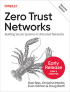
That said, be absolutely certain that you do not care about data confidentiality if you choose to not use encryption. While keeping data unencrypted is convenient for administrators, it is never legitimate if the data actually requires confidentiality. For instance, consider the scenario shown in Figure 8-1.
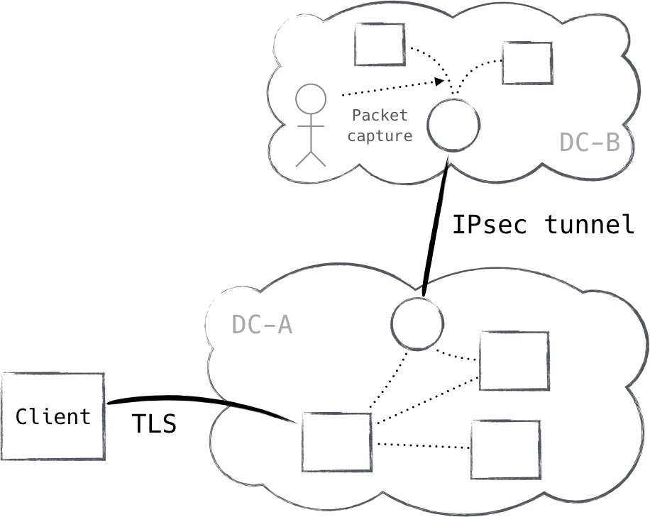
Figure 8-1. Confidentiality within the datacenter is just as important as outside the datacenter
This is an exceedingly common architecture. Note that it only encrypts traffic in certain areas, leaving the rest open (perhaps for the benefit of system administrators). Clearly, however, this data requires confidentiality, as it is encrypted in transit between sites.
This is a direct contradiction of the zero trust architecture, as it creates privileged zones in the network. Thus, citing good reasons to not encrypt traffic is a very slippery slope. In practice, systems that truly do not require confidentiality are rare. In addition to all of this, authentication is still required. There are few network protocols
which provide strong authentication but not encryption, and all of the transport protocols we discuss in this book provide authentication as well as encryption. If you look at it this way, encryption is attained “for free,” leaving few good reasons to exclude it.
Bootstrapping Trust: The First Packet
The first packet in a flow is oftentimes an onerous one. Depending on the type of connection, or point of the device lifecycle, this packet can carry with it very little trust.
We generally know what flows to expect inside the datacenter, but in client-facing systems, it’s anyone’s guess. These systems must be widely reachable, which greatly increases risk. We can use protocols like mutually authenticated TLS to authenticate the device before it is allowed to access the service; however, the attack surface in this scenario is still considerable, and the resources are also publicly discoverable.
So how do you allow only trusted connections, silently dropping all others, without answering a single unauthenticated packet? This is known as the first packet problem, and it is mitigated through a method called pre-authentication (Figure 8-2).
Pre-authentication can be thought of as the authorizing of an authentication request by setting an expectation for it. It is often accomplished by encrypting and/or signing a small piece of data and sending it to the resource as a UDP packet. The use of UDP for pre-authentication is important because UDP packets do not receive a response by default. This property allows us to “hide,” exposing ourselves only once we passively receive a packet encrypted with the right key.
Upon the passive receipt of a properly encrypted pre-authentication packet, we know we can expect the sender to begin authentication with us, and we can poke granular firewall holes allowing only the sender the ability to speak with our TLS server. This mode of pre-authentication operation is also known as Single Packet Authorization (SPA).
SPA is not a fully suited device authentication protocol. It merely helps to mitigate the first packet problem. Without downplaying the importance of the properties we gain by using pre-authentication, it must not be substituted for a more robust mutually authenticating protocol like TLS or IKE.
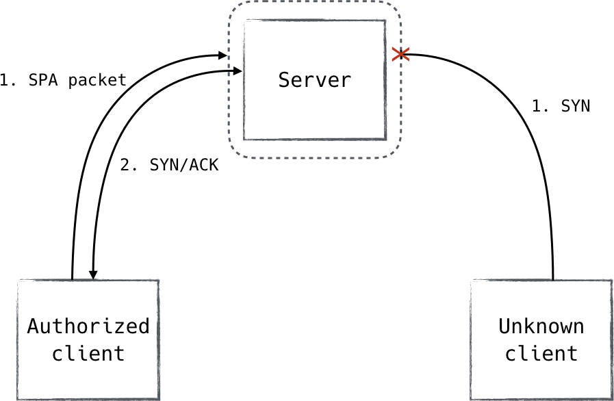
Figure 8-2. A client in possession of the pre-authorization key can send a signed packet in order to set an expectation for a TCP connection. Without it, no acknowledgments are sent.
FireWall KNock OPerator ( fwknop )
fwknop is an open-source tool that stands for “FireWall KNock OPerator” and uses Single Packet Authorization (SPA) for authorization.1 It is compatible with multiple operating systems and directly integrates with host firewalls to create temporary exceptions tightly scoped to specific needs.
Short-lived exceptions
When fwknop receives a valid SPA packet, its contents are decrypted and inspected. The decrypted payload includes protocol and port numbers which the sender is requesting access to. fwknop uses this to create firewall rules permitting traffic from the sender to those particular ports—rules that are removed after a configurable period of time. The default value is 30 seconds, but in practice, you may only need just a few seconds.
As mentioned, the rule which fwknop creates is tightly scoped. It permits only the sender’s IP address and only the destination ports requested by the sender. The destination ports which may be requested can be restricted via policy on a user-by-user basis. Additionally, it is possible for the sender to specify a source port, restricting the scope of the rule even further.
SPA payload
The fwknop SPA implementation has seven mandatory fields and three optional fields included in its payload. Among these are a username, the access request itself (which port, etc.), a timestamp, and a checksum:
-
16 bytes of random data
-
Local username
-
Local timestamp
-
fwknop version
-
SPA message type
-
Access request
-
SPA message digest (SHA-256 by default)
Once the client has generated the payload, it is encrypted, an optional HMAC is added, and the SPA packet is formed and transmitted.
Payload encryption
Two modes of encryption are supported: AES and GnuPG. The former being symmetric and the latter being asymmetric, two options are provided in order to cater to multiple use cases and preferences.
Personal applications or small installations might prefer AES since it does not require any GnuPG tooling. AES is also more performant with regard to data volume and computational overhead. It does have some downsides though, practically all of which originate from the fact that it is a symmetric algorithm.
Symmetric encryption comes with difficult key distribution problems, and beyond a certain scale, these challenges can grow to be untenable. Leveraging the GnuPG encryption mode solves most of these problems and is the recommended mode of operation, despite being less performant than its counterpart.
HMAC
fwknop can be configured to add an HMAC to the end of its payload. A hashed message authentication code (HMAC) prevents tampering by guaranteeing that the message is authentic. This is important because otherwise an attacker could arbitrarily modify the ciphertext, and the receiver would be forced to process it.
You may have noticed that there is a message digest which is calculated and stored along with the plain text. This digest helps to mitigate attacks in which the ciphertext is modified, but is also less than ideal, as this method (known as authenticate-then- encrypt or AtE) is vulnerable to a few niche classes of attacks. Adding an HMAC to the encrypted payload prevents these attacks from being effective.
In addition, decryption routines are generally much more complex than HMAC routines, meaning they are more likely to suffer from a vulnerability. Applying an HMAC to the ciphertext allows the receiver to perform a lightweight integrity check, helping to ensure that we are only sending trusted data to the decryption routines. It is strongly recommended to configure fwknop to use HMAC.
A Brief Introduction to Network Models
Networking stacks have many different responsibilities in transmitting data over a network. As such, it would be easy for a networking stack to become a jumbled mess of code. Therefore, the industry long ago decided to spend the effort to clearly define a set of standardized layers in a networking stack. Each layer is responsible for some portion of the job of transmitting data over the wire. Lower layers deliver functionality and guarantees to higher layers in the stack.
Building up these layers isn’t just useful for organizing code. These layer definitions are often used to describe where new technology operates in the stack. For example, you might have heard of a layer 7 or layer 4 load balancer. A load balancer distributes traffic load across a set of backend machines, but the layer at which it operates greatly determines its capabilities. A layer 7 load balancer, for example, can make decisions about where to route traffic based on details in an HTTP request like the requested
path or a particular header. HTTP operates at layer 7, so this data is available to inspect. A layer 4 load balancer, by contrast, does not consider layer 7 data and therefore can only pass traffic based on simpler connection details like the source IP and port.
There are many different network models. Most of these models can be roughly mapped to equivalents in other network models, but sometimes the boundaries can be a bit fuzzy. For this book, we will only focus on two network models: the OSI network model and the TCP/IP network model. Understanding the boundaries of these two models will help in later discussions about where zero trust responsibilities should be handled in the network model.
Network Layers, Visually
The idea of a layer might be strange at first, though a simplistic way to understand the concept is by comparing them to Russian nesting dolls. Each layer typically contains the next, encapsulated by it in a section known as the payload (Figure 8-3).
Figure 8-3. Lower network layers transport higher-layer traffic in their payload fields, creating a nested structure inside a single packet
OSI Network Model
The OSI network model was published in 1984 after being merged from two separate documents started several years earlier. The model is published by two separate standards bodies: the International Organization for Standardization (ISO) published ISO 7498, while the Telecommunications Standardization Sector of the International Telecommunication Union (ITU-T) published X.200.
The model itself is extracted from the experiences building several networks at the time, ARPANET being the most well known. The model defines seven distinct layers (explained in the following sections), each of which owns a portion of the responsibilities for transmitting data.
Layer 1—Physical Layer
The physical layer is defined as the interface between a network device and the physical medium over which network transmission occurs. This can include things like pin layout, line impedance, voltage, and frequency. The parameters of the physical layer (sometimes referred to as a PHY) depend on the kind of medium used. Twisted pair, coaxial cabling, and radio waves are examples of mediums in common use today.
Layer 2—Data Link Layer
The data link layer is responsible for the transmission of data over the physical layer. This layer only considers data transmission between directly connected nodes. There is no concept of transmission between interconnected networks. Ethernet (802.3) is the most well-known protocol operating at this layer.
Layer 3—Network Layer
The network layer is responsible for transmitting data packets between two interconnected nodes. At this layer, packets might need to transverse multiple layer 2 segments to reach their destination, so this includes concepts to allow routing data to its destination by inspecting a destination address. IP is often said to operate at this layer, but the boundaries can be a bit fuzzy, as we will explore later.
Layer 4—Transport Layer
The transport layer builds upon the simple packet transmission capabilities of layer 3, usually as an intermediary protocol designed to augment layer 3 with many desirable services:
-
Stateful connections
-
Multiplexing
-
Ordered delivery
-
Flow control
-
Retransmission
These services might look similar to the services that a protocol like TCP provides. In fact, TCP is a layer 4 protocol; however, in a way similar to IP, this association can be a bit awkward.
Not all of these services need to be provided by a protocol operating at this level. UDP, for example, is a layer 4 protocol which offers only one of these services (multiplexing). It remains a layer 4 protocol because it is an intermediary protocol which is directly encapsulated by layer 3.
Layer 5—Session Layer
The session layer isn’t commonly discussed in most networks. This layer provides an additional layer of state over connections, allowing for a communication resumption and communication through an intermediary. Several VPN (PPTP, L2TP) and proxy protocols (SOCKS) operate at this layer.
Layer 6—Presentation Layer
The presentation layer is the layer that application developers will most commonly interact with. This layer is responsible for handling the translation between application data (often represented as structural data) and transmittable data streams. In addition to this serialization responsibility, this layer is often responsible for crosscutting concerns like encryption and compression. TLS is a well-known protocol operating at this layer, though it operates at layer 6 only after the session is established (which happens at layer 5—the process of changing from a lower layer to a higher layer is sometimes referred to as an upgrade).
Layer 7—Application Layer
The application layer is the highest layer in the OSI model. This layer provides the high-level communication protocols that an application uses to communicate on the network. Some common protocols at this layer are DNS, HTTP, and SSH.
TCP/IP Network Model
The TCP/IP network model is another important network model. This model deals with the protocols most often found on the internet today.
Unlike the OSI model, the TCP/IP model does not try to define strict layers with clear boundaries. In fact, RFC 3439 (https://www.ietf.org/rfc/rfc3439.txt), which documents the “philosophical guidelines” that internet architects use has a section entitled “Layering Considered Harmful.” Still, the model is said to define the following rough layers, from lowest to highest:
-
Link layer
-
Internet layer
-
Transport layer
-
Application layer
These layers can be roughly mapped to the OSI model, but the mappings are only best effort. The application layer roughly covers layers 5–7 in the OSI model. The transport layer roughly maps to layer 4, though its introduction of the concept of a port gives it some layer 5 characteristics. The internet layer is similarly generally associated with layer 3. The abstraction is leaky, however, as higher-level protocols like ICMP (which are transmitted via IP) concern themselves with details of how traffic is routed around the internet.
Where Should Zero Trust Be in the Network Model?
With a better understanding of network layer models, we can now take a look at where to best apply zero trust controls in the network stack.
There are two predominant network security suites: TLS and IPsec. TLS (Transport Layer Security, to which SSL is a predecessor) is the most common of the two. Many application layer protocols support TLS to secure traffic. IPsec is an alternative protocol, more commonly used to secure things like VPNs.
Despite having “transport” in its name, TLS does not live in the transport layer of the TCP/IP model. It is found in the application layer (somewhere between layer 5 and 6 in the OSI model), and as such, is largely an application concern.
TLS as an Infrastructure Concern
Perimeter networks frequently abstract TLS away from applications, shifting the responsibility from the application to the infrastructure. In this mode, TLS is “terminated” by a dedicated device
at the perimeter, forwarding the decrypted traffic to a backend service. While this mode of operation is not possible in a zero trust network, there remain a handful of strategies for deploying TLS as an infrastructure concern while still conforming to the zero trust model. More on that later.
IPsec, by contrast, is generally considered part of the internet layer in the TCP/IP model (layer 3 or 4 in the OSI model, depending on interpretation). Being further down the stack, IPsec is usually implemented in a host’s kernel. IPsec was developed for the IPv6 specification. It was originally a requirement for IPv6, but was eventually downgraded to a recommended status.
With two alternatives to secure network transit, the question becomes, is one preferred over the other? Zero trust’s goal is secure communication for all traffic. The best way to accomplish this goal is to build systems that provide secure communication by default. IPsec, being a low-level service, is well positioned to provide this service.
Using IPsec, host-to-host communication can be definitively secured. Being integrated deep in the network stack, IPsec can be configured to only allow packet transmission once a secure communication channel has been established. Furthermore, the receiving side can be configured to only process packets that have been sent securely. In this system, we have essentially created a “secure virtual wire” between two hosts over which only secured traffic can flow. This is a huge benefit over traditional security initiatives that add secure communication one application at a time. Simply securing communications between two devices is not sufficient to build a zero trust network. We need to ensure that each individual network flow is authorized. There are several options for meeting this need:
-
IPsec can use a unique security association (SA) per application (see RFC 4301, section 4.4.1.1 (https://tools.ietf.org/html/rfc4301#section-4.4.1.1)). Only authorized flows are then allowed to construct these security policies.
-
Filtering systems (software firewalls) can be layered on top of IPsec. We will discuss the role of filtering in zero trust later in this chapter.
-
Application-level authorization should be used to ensure that communications are authorized. This could use standard authorization techniques, such as access tokens or X.509 certificates, while delegating strong encryption and authentication responsibilities to the IPsec stack.
-
For a truly “belt and suspenders” system, mutually authenticated TLS could be layered on top of the existing IPsec layer. This defense-in-depth approach provides two layers of encryption (mTLS and IPsec), protecting communication should one of them become compromised, at the expense of complexity and increased overhead.
Client and Server Split
While IPsec has a number of beneficial properties, its lack of popularity presents real world obstacles for its use in systems today. The issues one will see can be broken down into three areas:
-
Network support issues
-
Device support issues
-
Application support issues
Network support issues
Network support can hamper the use of IPsec in the wild. IPsec introduces several new protocols, two of which (ESP and AH) are new IP protocols. While these protocols are fully supported in simple LAN networks, on some networks, getting these packets transmitted can be quite a challenge. This could be due to misconfigured firewalls, NAT traversal, or routers being purposefully configured to not allow traffic to flow. For example, Amazon Web Services, a large public cloud provider, does not allow ESP or AH traffic to be transmitted on its networks. Public hotspots like those found at businesses or libraries also often have spotty support for IPsec traffic. To mitigate these issues, IPsec includes support for encapsulating traffic in a UDP frame (depicted in Figure 8-4). This encapsulation allows an inhospitable network to transmit the traffic, but it adds extra complexity to the system.
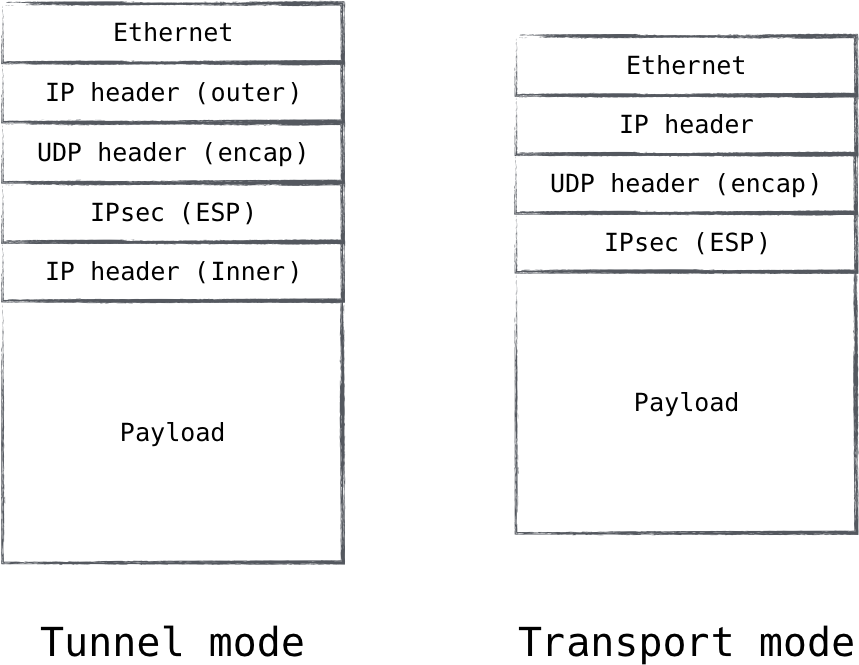
Figure 8-4. IPsec supports encapsulating ESP packets in a UDP packet, making it look like normal UDP traffic
Device support issues
Device support can also be a major factor in rolling out an IPsec-protected network. The IPsec standard is complex, with many configuration options and cipher suites. Both hosts in the relationship need to agree to a common protocol and cipher suite before communication can flow. Cipher suites in particular frequently need to be adjusted as compromises are revealed. Finding that a stronger cipher suite has not
been implemented is a real issue in IPsec systems. To be fair, TLS needs to handle these same issues; but due to the nature of having IPsec implemented in the system’s kernel, progress on newer protocols and cipher suites is naturally slower.
IPsec also requires active configuration of the devices in the relationship. In a client/server system with varying device capabilities, configuring the client devices can be rather challenging. Desktop operating systems can usually be configured to support the less popular protocol. Mobile operating systems, however, are less likely to fully support IPsec in a way that conforms to the zero trust model.
Application support issues
IPsec places additional requirements on the system configuration versus typical TLSbased security. A system wanting to make use of IPsec needs to configure IPsec policy, enable kernel support for the desired cipher suites, and run an IKE daemon to facilitate the negotiation of IPsec security associations. When compared to a library-based approach for TLS, this extra complexity can be daunting. This is doubly so when many applications already come with built-in TLS support, which seemingly offers a turnkey solution for network security.
It should be noted that while the library approach seems more attractive at first glance, in practice it presents quite a bit of hidden complexity. Being a library, applications need to expose configuration controls to the TLS library. Applications frequently support the more common server TLS, but neglect to expose configuration for presenting a client certificate that is required to create a mutually authenticated TLS connection. Additionally, system administrators may need to adjust configuration in reaction to recently exposed vulnerability. With a large set of applications, finding the application-specific configuration that needs to be adjusted can hamper the rollout of a critical fix.
The web browser is frequently the common access point into organizational systems. Its support for modern TLS is generally very good (assuming organizations stay up to date on the latest browser versions). This common access point mitigates the issue of configuration, as there is a small set of target applications that need to be adjusted. On the server side, many organizations are turning toward a model where network communication is secured via a local daemon. This approach centralizes configuration in a single application and allows for a base layer of network security to be supplied by the system administrator. In a way, it looks very similar to the IPsec model, but implemented using TLS instead.
A pragmatic approach
Given all the pluses and minuses of the two approaches, a pragmatic solution seems available to system administrators.
For client/server interactions, mutually authenticated TLS seems to be the most reasonable approach to network security. This approach would typically involve configuring a browser to present client certificates to server-side access proxies which will ensure that the connection is authenticated and authorized. Of course, this restricts the use of zero trust to browser-based applications.
For server/server interactions, IPsec seems more approachable. The server fleet is generally under more controlled configuration, and the network environment is more well known. For networks which don’t support IPsec, UDP encapsulation can be used to avoid network transit issues.
Microsoft Server Isolation
For environments which fully employ Microsoft Windows with Active Directory, a feature called server isolation is particularly attractive. By leveraging Windows Firewall, Network Policy, and Group Policy, server isolation provides a framework through which IPsec configuration can be automated. Furthermore, server isolation can be tied to Active Directory security groups, providing fine-grained access control which is backed by strong IPsec authentication. While complications surrounding IPsec transit over public networks still exist, server isolation is perhaps the most pragmatic approach for obtaining zero trust semantics in a Windows-based environment.
Since the IPv6 standard includes IPsec, the authors hope that it will become a more viable solution for both types of network communication as network adoption progresses.
The Protocols
We learned about mutually authenticated TLS and IPsec in the previous section, as well as when you might use one versus the other. In this section, we’ll discuss the two protocols in detail. It is very important to understand the inner workings of these protocols as you deploy them, since there are many configuration controls in them. Both are complicated in their own right, and insecure configurations are common.
IKE/IPsec
Internet Key Exchange (IKE) is a protocol which performs the authentication and key exchange components of IPsec. It is typically implemented as a daemon and uses a pre-shared key or an X.509 certificate to authenticate a peer and create a secure session. Inside this secure session, another key exchange is made. The results of this second key exchange are then used to set up an IPsec security association, the parameters of which are leveraged for bulk data transfer. Let’s take a closer look.
IKEv1 Versus IKEv2
There are two versions of IKE, and most software suites support both. For all new deployments, it is strongly recommended to use IKEv2. It is both more flexible and more reliable than its predecessor, which was overly complicated and less performant. For the purposes of this book, we will be talking about IKEv2 exclusively.
IKE and IPsec
There is frequent confusion around the relationship between IKE and IPsec. The reality is that IPsec is not a single protocol; it is a collection of protocols. IKE is often considered part of the IPsec protocol suite, though its design makes it feel complimentary as opposed to a core component. IKE can be thought of as the control plane of IPsec. It handles session negotiation and authentication, using the results of the negotiation to configure the endpoints with session keys and encryption algorithms.
Since the core IPsec protocols are embedded in the IP stack, IPsec implementations are typically found in the kernel. With key exchange being a relatively complex mechanism, IKE is implemented as a user space daemon. The kernel holds state defining active IPsec security associations, and traffic selectors defining which packets IPsec policy should be applied to. The IKE daemon handles everything else, including the negotiation of the IPsec security association (SA) itself (which is subsequently installed into the kernel for use).
Authentication credentials
IKEv2 supports both pre-shared keys and X.509 public/private key pairs. In addition, it supports the Extensible Authentication Protocol (EAP). Supporting EAP means that IKEv2 supports a bevy of other authentication methods (including support for multifactor authentication) by proxy. We will avoid analyzing EAP directly, however, as the ecosystem is very large.
It goes without saying that X.509 certificates are the preferred method of authentication for IKE. While pre-shared keys are supported, we strongly recommend against them. They present major distribution and generation challenges, but most importantly, they are meant for humans to remember.
X.509 certificates are not meant for humans; they’re meant for devices. They carry with them not only proof of trust, but also signed metadata and a way to strongly encrypt data using its identity. These are powerful properties, and the reason certificates are the undisputed champion of device authentication credentials.
IKE SA_INIT and AUTH
All IKEv2 exchanges begin with a pair of packets named IKE_SA_INIT. This initial exchange handles cryptographic suite selection, as well as a Diffie–Hellman exchange. The Diffie–Hellman key exchange provides a method for two systems to negotiate a session key without ever transmitting it.
The resulting session key is used to encrypt fields in the next pair of messages: the IKE_AUTH packets. In this step, the endpoints exchange certificates and generate what is known as a CHILD_SA. The CHILD_SA contains the IPsec parameters for a security association between the two endpoints, and the IKE daemon then programs these parameters into the kernel. From this point forward, the kernel will encrypt all traffic matching the selectors.
Cipher suite selection
Cipher choice with IPsec is slightly less trivial than TLS. This is because IPsec is implemented in the kernel, making cipher support a little more stringent than it would be if it were simply a software package. As a result, a wide variety of devices and operating system versions will complicate IPsec deployments.
RFC 6379 (https://tools.ietf.org/html/rfc6379) sets forth what is known as the Suite B Cryptographic Suite. It was authored by the US National Security Agency, and is (at the time of this writing) a widely accepted standard when it comes to selecting IPsec cipher suites.
Much like TLS, IKE cipher suites include algorithms for key exchange, bulk encryption, and integrity. Unlike TLS, it does not include authentication, as IKE takes care of that outside of the crypto suite selection.
RFC 6379 is fairly prescriptive with regard to these choices. All of the suites defined in Suite B leverage varying strengths of the AES encryption algorithm and the ECDH key agreement protocol. They leverage GCM and SHA for integrity. For the majority of use cases, Suite B is recommended.
There are a couple instances in which Suite B might not be appropriate. The first is that not all IPsec implementations support elliptic curve cryptography, which is mandated. The second is concern around the security of popularized elliptic curve implementations, as many believe that state actors have interfered with them in order to subvert the security they aim to provide.
In consideration of either of these cases, equivalent-strength DH is recommended as a good alternative.
IPsec security associations
IPsec security associations (SAs) are the end result of an IKE negotiation and describe what is sometimes referred to as a “relationship” with the remote endpoint. They are unidirectional, so for a relationship between two endpoints, you will normally find two SAs (inbound and outbound).
An IPsec SA is uniquely identified by an SPI (Security Parameter Index, not to be confused with an IKE SPI) and has a limited lifetime. As traffic traverses the IP stack, the kernel finds packets matching the selector(s) and checks to see if there is an active security association for the selector in question. If there is an entry, the kernel encrypts the packet according to the parameters defined in the SA, and transmits it. If there is no entry, the kernel will signal the IKE daemon to negotiate one.
An IPsec SA has four distinct states in its lifecycle: larval, mature, dying, and dead. A larval SA is one that is still being negotiated by the IKE daemon and has only part of its state installed. Once the negotiation is complete, the SA progresses to the mature state, in which it begins encrypting traffic. As the SA nears the end of its lifetime, a new SA is negotiated and installed with the same policy. The original SA progresses to the dying state, and all relevant traffic switches over to the new SA. After some time, the old SA expires and is marked as dead.
IPsec tunnel mode versus transport mode
IPsec supports two modes of operation, tunnel mode and transport mode (Figure 8-5). Tunnel mode is by far the most widely deployed variant. When IPsec operates in tunnel mode, an SA is formed with the remote endpoint which is used to encapsulate IP packets and secure it en route to the endpoint. This encapsulation covers the entirety of the IP packet, including the IP header. This means that in tunnel mode, the IPsec endpoint can be different than the endpoint for which the IP traffic is destined, since a new IP header will be exposed once the protected traffic is unpacked.
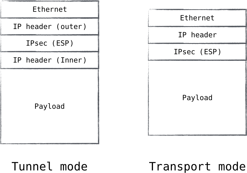
Figure 8-5. IPsec tunnel mode allows traffic from one network to be tunneled into another
This is why it is called tunnel mode. It is frequently used in VPNs, where one wishes to make a secure connection to a remote network, enabling administrators to tunnel flows destined for that network through the secure channel. This brings an interesting realization though in the world of zero trust networks: tunnel mode, by its very nature, strongly implies that the traffic will become unprotected at some point in time. Security is ensured between the sender and a network intermediary, but after that all bets are off. It is the opinion of the authors that, for this reason, the use of tunnel mode contradicts the zero trust architecture.
Transport mode, on the other hand, offers practically identical security guarantees, just minus the tunnel part. Instead of encapsulating an entire IP packet, it encapsulates only the IP payload. This is useful for direct host-to-host IP communication. Rather than establishing a security association with an intermediary network device, transport mode establishes a security association directly with the endpoint to which the traffic is addressed, ensuring security is applied end to end. This property allows transport mode to fit nicely into the zero trust model.
While transport mode is the obvious choice for a full-blown zero trust datacenter architecture, it is important to remain realistic. Zero trust migrations are difficult, and IPsec tunnel mode is still a tool which can be leveraged along the journey to a homogeneous zero trust architecture.
IKE/IPsec for device authentication
When it comes to device security in a zero trust network, we are looking to provide not only authentication for the device, but also device-to-device transport security. This is exactly what IPsec is designed to do, and the reason that it is perhaps the best protocol for the job.
Since IPsec is implemented directly on top of IP, it can handle most application traffic, not just TCP or UDP. Additionally, since it is implemented in the kernel, the applications being protected need no knowledge of the underlying security. They simply run as they would normally, and the traffic gets encrypted “for free.” This encryption and authenticity may come “for free” from the perspective of the application, but that is certainly not the case for the device! As you can see, the configuration of IPsec is nontrivial, and managing the multitude of policies can be challenging (or impossible without automation).
Another consideration is how widely supported IPsec is as a network protocol. Not all public networks (e.g., coffee shops) support IPsec and may even actively block it. Difficulty in configuration and lack of universal support make IPsec less desirable for client-side zero trust networks. However, those pain points don’t typically exist inside the datacenter, where IPsec remains a front contender with regard to device security protocols.
Mutually Authenticated TLS
Commonly referred to by the name of its predecessor, Transport Layer Security (TLS) is the protocol most commonly used to secure web traffic. It is a mature and well understood protocol, is widely deployed and supported, and is already trusted with some of the most sensitive tasks, like banking transactions. It is the “S” in HTTPS.
When TLS is used to secure web sessions, the client validates that the server certificate is valid, but the server rarely validates the client. In fact, the client rarely presents a certificate at all! The “mutual” prefix for TLS is meant to denote a TLS configuration in which client certificate validation is required (and thus, mutually authenticated). While a lack of client authentication may be acceptable for services that are being published to the general public, it is not acceptable for any other use case. Mutual authentication is a requirement for security protocols conforming to the zero trust model, and TLS is no exception.
The basics of a TLS handshake are fairly straightforward, as shown in Figure 8-6. A client initiates the session with a ClientHello message sent to the server, which includes a compatibility list for things like cipher suites and compression methods. The server chooses parameters from the compatibility list and replies with a Server‐Hello defining the selections it made, followed by the server’s X.509 certificate. It also requests the client’s certificate at this time.
The client then generates a secret key and uses the server’s public key to encrypt it. It sends the server this encrypted secret key, as well as its client certificate, and a small bit of proof that it is in fact the owner of that certificate. The secret key generated by the client is ultimately used to derive several additional keys, including one which acts as a symmetric session key. So, once the client sends these details off, it has enough information to set up its side of the encrypted session. It signals the server that it is switching to session encryption, the server validates the client, sends a similar message in return, and the session is fully upgraded.
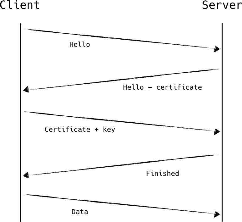
Figure 8-6. A simplified diagram showing a mutually authenticated TLS handshake using RSA key exchange
Cipher suite negotiation and selection
TLS supports many different kinds of authentication and encryption. A cipher suite is a named combination of these components. There are four primary components in a TLS cipher suite:
-
Key exchange
-
Authentication
-
Bulk encryption
-
Message authenticity
Choosing the right set of supported cipher suites is important in ensuring your TLS deployments remain secure. Many cipher suites are known to be weak. At the same time, the strongest cipher suites are poorly supported among clients in the wild.
Who gets to say.
During the TLS handshake, the client presents its list of supported cipher suites in order of preference. The server gets to choose one from this list, assuming that there is shared support at all, in which case the session will fail to establish. While the client gets to communicate its cipher preferences to the server, it is ultimately the server which is allowed to choose. This is important because it preserves the client/server, consumer/operator relationship.
With this, the overall security of the system is limited to the strongest negotiable cipher suite of the weakest client. Historically, many online resources support weak cipher suites in a bid to maintain backward compatibility with older clients. Knowing this, there have been many attacks against cipher suite negotiation, including downgrade attacks which enable an attacker to actively weaken the encryption algorithm used by a client.
As a result, it is recommended that servers support only the strongest set of cipher suites that is reasonable. In the case of datacenter deployments, this list might be limited to only a few approved suites, as there is strict control over the “clients.” This is not always reasonable for true client-facing deployments, however.
Negotiation as a Weakness
Cipher suite negotiation is, for the stated reasons, considered an anti-pattern in modern cryptographic protocols. Newer protocols and frameworks such as Noise aim to eliminate protocol negotiation. Work in this area is highly active at the time of this writing, and the authors look forward to widespread adoption of cryptographic protocols which lack weaknesses such as this one.
Key exchange.
The TLS key exchange describes the process for securely generating an encryption key over an insecure channel. Sometimes described as a key agreement or exchange protocols, these protocols use mathematical functions to agree on keys without ever transmitting them in the clear (or in most cases, at all).
There are three primary key exchange/agreement protocols in popular use with TLS. They are, in rough order of preference: ECDHE, DHE, and RSA.
ECDHE is based on a Diffie–Hellman exchange, using elliptic curves to agree on a key. Elliptic curve cryptography is very strong, efficient, and is based on a mathematical problem which remains difficult to solve. It is the ideal choice for security and performance considerations.
DHE is also based on a Diffie–Hellman exchange, except it uses modular arithmetic to agree on a key, rather than elliptic curves. In order for these exchanges to be strong, they require larger keys than ECDHE. This is because the math involved for regular DHE is well solved, and we are getting better and better at solving those problems. So, while DHE can provide security similar to that of ECDHE, it is less performant in doing so.
RSA key exchange is based on the same asymmetric operations that prove identity for digital signatures (e.g., X.509 certificates). It uses the public key of the server to encrypt the shared secret for transmission. This key exchange protocol is widely supported, although it has two primary limitations: it requires use of RSA-based authentication, and it does not provide perfect forward secrecy.
Quantum Vulnerability
The security of practically all public key cryptography in popular use today is based on the assumption that factoring large numbers is a hard, computationally expensive problem. This assumption, however, is invalid when considering quantum computation. Classical computing must rely on a technique known as the general number field sieve in order to derive the factors of large numbers. It’s an algorithm that is relatively inefficient. Shor’s algorithm, on the other hand, is a quantum algorithm that is exponentially more efficient than the general number field sieve. It can be used to rapidly break most asymmetric key exchanges, given a sufficiently powerful quantum computer.
Quantum-resistant protocols are under active development at the time of this writing. While none is quite ready for production, the looming quantum threat should not deter one from implementing public key cryptography today. It remains the best tool we have, and cryptographers are working hard to define a clear path forward. For more information, check out the Post-Quantum Cryptography conference (https://pqcrypto.org/).
Perfect Forward Secrecy.
PFS, or perfect forward secrecy, is a cryptographic property in which the disclosure of a private key does not result in the compromise of previously negotiated sessions. This is a valuable property because it ensures that an eavesdropper cannot record your session data for later decryption. The RSA key exchange does not support PFS because the session key is directly encrypted and transmitted using the private key. DHE or ECDHE must be used in order to obtain PFS.
Mind Your Curves.
Cryptography experts have called into question the security of many elliptic curve-based key agreement implementations. While the math and fundamental principles are sound, a standardized set of curves are typically used as the input for these functions. These standard curves rely on a set of constants, which must remain secure in order to maintain the integrity of cryptographic operations performed with the resulting curves.
It is these constants which have been questioned. It is believed by some of the brightest minds in the industry that the constants which are widely available for these purposes have been manipulated by state actors and are compromised. If this is true, it stands to reason that any elliptic curve crypto implementation leveraging these well known constants has in fact been secretly subverted.
For this reason, some experts recommend use of DHE key agreement over ECDHE, despite its better math and performance properties. This is problematic in some places, since not all clients fully support DHE (most famously, Internet Explorer does not support DHE in combination with RSA authentication). The recommended course of action in this case is to curate server-side cipher suites to prefer DHE negotiation where available, falling back to ECDHE when necessary.
Authentication.
There are three common authentication methods, one of which is on its way out: RSA, DSA, and ECDSA.
RSA authentication is overwhelmingly the most common, in use in over 99% of web based TLS resources. Generally speaking, RSA is a safe bet so long as a sufficiently sized key is used. This caveat raises the concern that we are getting better at solving the mathematical problem at the heart of the RSA algorithm, requiring key sizes to increase in order to keep up with advances. Despite this, RSA remains the most popular and most often recommended authentication method.
DSA authentication is no longer recommended. While it is (for the most part) a sound technology at its core, a series of other problems have artificially weakened it, including adoption and opinionated standardization. ECDSA, on the other hand, is the newer cousin of DSA and uses elliptic curves to facilitate public/private key pairs. ECDSA is frequently touted as the future. It applies all the benefits of elliptic curve cryptography to the authentication component, including smaller key size and better
performance and mathematical properties. It is presumed, however, that ECDSA authentication is susceptible to the use of malicious elliptic curves, as described in “Mind Your Curves” on page [XX].
When making a decision between RSA and ECDSA authentication, the brokenness of widely published elliptic curves should be carefully considered. Identity compromise can be catastrophic. Additionally, ECDSA is not nearly as widely supported as RSA is. With the acknowledgment of these two points, it is fair to say that RSA authentication is still a good choice at the time of this writing, despite the existence of a technologically superior algorithm (ECDSA).
Separation of duty
For the purposes of a zero trust network, it is a good idea to separate the encryption duties from the application itself (Figure 8-7). The resource we are securing in this case is the device, and as such, it makes a lot of sense for this piece to be independent of the workload itself.
Doing this also alleviates a number of pain points, including zero-day mitigation, performance penalties, and auditing. For protocols like IPsec, this separation of duty is part of the design, but this is not the case for TLS. Historically, applications speak TLS directly, loading and configuring shared TLS libraries for remote communication. We have seen this pattern’s rough spots time and time again. Shared libraries become littered throughout the infrastructure, being consumed by a multitude of projects, all with independent versions and configurations. Some languages have more flexible libraries than others, limiting your ability to enforce the latest and greatest. Above all, it is very difficult to ensure that all these applications are indeed consuming TLS the right way, and remain up to date with regard to known vulnerabilities.
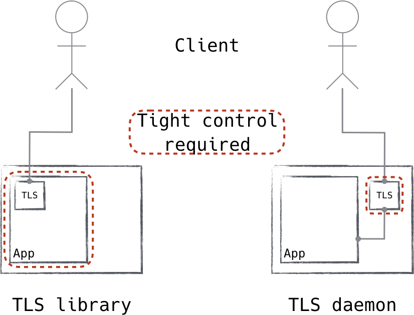
Figure 8-7. Traditional applications include TLS libraries and perform those duties themselves. Using a local TLS daemon instead means better control and consistent performance.
To address the problem, it is useful to move the handling of TLS configuration to the control plane. Connections to the service are brokered by the TLS daemon then locally forwarded to the application. The TLS daemon is configured with system certificates, trust authorities, and endpoint information—that’s about it.
In this way, we can ensure that all software receives device authentication and security with TLS, regardless of its support for it. Additionally, since zero trust networks whitelist flows, we can ensure that application traffic is protected by limiting whitelisted flows to known TLS endpoints.
Bulk encryption
All the TLS intricacies and components discussed up to this point apply primarily to the initial TLS handshake. The TLS handshake serves two primary purposes: authentication and the creation of session keys.
TLS handshakes are computationally expensive due to the mathematical operations required to make and validate them. This is a distinct trade-off between security and performance. While we strongly desire this level of security, the performance impact is prohibitively expensive if we apply these operations to all communications.
Asymmetric cryptography is extraordinarily important in the process of secure introduction and authentication, but its strength can be matched by symmetric cryptography so long as identity or authentication is not a concern. Symmetric encryption uses a single secret key instead of a public/private key pair, and is less computationally expensive than asymmetric cryptography by orders of magnitude. This is where the concept of a TLS handshake and session keys comes in.
Some very smart mathematicians and cryptographers realized that we can use the strong yet expensive operations to securely generate a single secret—one which can be shared between the parties (Figure 8-8). The key exchange component of TLS is that which generates this shared key and ensures that both parties have knowledge of it.
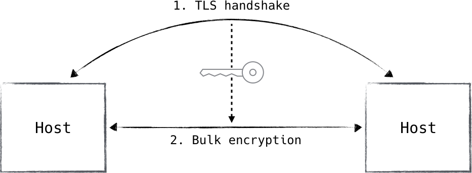
Figure 8-8. TLS handshake generates a symmetric encryption key for bulk transfer. IPsec uses a similar mechanism.
This shared key is then used as the input for a symmetric encryption algorithm, which is applied to all session traffic following the handshake. This methodology ensures that the entire session benefits from the strength of asymmetric cryptography without inheriting any of the performance implications associated with asymmetric encryption schemes.
When it comes to choices for bulk encryption algorithms, TLS supports many, but the recommendation is pretty well aligned across the board: just use AES. It checks all the desirable boxes, including the fact that it is unpatented, widely implemented in hardware, and practically universally implemented in software. It is very performant, heavily vetted/scrutinized, and remains unbroken to the best of public knowledge.
Many people say “AES is good enough,” and while that might be a tough pill to swallow when it comes to security protocols, such a statement has never been so close to the truth.
Message authenticity
When communicating securely, message authenticity is an important if not required property. Encryption provides confidentiality, but without message authenticity, how do you ensure the integrity of that message? Without an error during decryption, it is difficult or impossible to distinguish a tampered message from an authentic one. Some encryption modes (such as AES-GCM) provide message confidentiality and authenticity guarantees simultaneously. However, these guarantees are only applicable during bulk encryption; there are several TLS exchanges which are not protected by the bulk transfer specifications, and the message authenticity scheme protects those as well.
Explicit Authenticity Sometimes Required
Since some bulk encryption algorithms provide message integrity assurances, it is not always necessary to perform explicit authenticity checks on every packet. Instead, TLS will prefer built-in assurances for bulk transfers and rely on explicit authenticity checks for all packets not associated with the bulk transfer (for instance, TLS control messages).
As far as choice goes, the options are limited to MD5 and the SHA family of hashes. The former has been cryptographically broken for quite some time now, leaving the SHA family as the only reasonable choice for ensuring message integrity under TLS. There are even concerns when using the weaker SHA variant, SHA-1, as it is now considered vulnerable in the face of ever-increasing compute power. As such, it is recommended to choose the strongest SHA hash which can be reasonably deployed, given hardware and software constraints.
It is additionally recommended to use bulk encryption with built-in authenticity wherever possible, as it is generally more performant and secure than relying on a disjoint authenticity mechanism. TLS version 1.3 mandates the use of authenticated encryption.
Mutually authenticated TLS for device authentication
Just like any other protocol used for device authentication, TLS comes with its ups and downs.
The first is that, due to its position in the network stack, TLS is protocol-dependent. It is most commonly implemented as a TCP-based protocol, though a UDP-based variant dubbed DTLS is also available. The presence of DTLS highlights the deficiency of the position of TLS in the stack. With this, TLS suffers diminishing returns when used to secure IP protocols other than those which it natively supports, like TCP or UDP.
Another thing to consider is the automation requirement. TLS is commonly deployed as an infrastructure service in perimeter networks by leveraging intermediaries which are typically positioned at the perimeter. This mode of operation, however, is unsuitable for a zero trust network as long as the intermediary and the upstream endpoint are separated by a computer network. In a zero trust network, applications leveraging a TLS-speaking intermediary must be on the same host as the intermediary itself. As a result, protecting datacenter zero trust networks with TLS requires additional automation to configure applications to speak through this layer of external security. It does not come “for free” like other protocols such as IPsec.
All of that said, it remains today’s best choice for protecting client-facing zero trust networks. TLS is very widely supported in both software and transit (i.e., intermediary networks worldwide), and can be relied upon for straightforward and trustworthy operation. Most web browsers support mutually authenticated TLS natively, which means that resources can be protected using zero trust principles without the immediate need for specialized client-side software.
Trusting Cloud Traffic: Challenges and Considerations
The cloud has opened up a world of possibilities for organizations, allowing businesses to scale quickly and access unlimited resources. However, this newfound freedom also comes with challenges, particularly around trusting traffic from the cloud environments. There are several challenges when transitioning to cloud systems, which include maintaining compliance and security standards, securing against cyber threats, ensuring network visibility, navigating the variety of cloud providers available, and keeping costs reasonable.
Compliance and Security: One of the primary concerns of trusting cloud traffic is ensuring compliance with regulations and security best practices. Organizations moving their infrastructure to the cloud must ensure their data is secure and not shared with unauthorized parties, which can be a challenge in multi-tenant public cloud environments, as the data of multiple organizations are often stored on the same physical server. Keeping up-to-date with the latest regulations and security protocols is crucial to avoid data leakage, compliance violations, and other severe consequences.
Cyber Threats: Cloud environments are vulnerable to a range of cyber threats, including malicious actors targeting the platform itself (e.g., distributed denial-of-service attacks) and threats that target individual users and their data (e.g., phishing scams or ransomware). Additionally, cloud providers have become increasingly attractive targets for state-sponsored actors due to the large amounts of data stored in these environments, making it essential to have robust security measures.
Network Visibility: Traditional on-premise solutions are often limited by physical constraints, whereas cloud networks are often more flexible and expansive. Organizations must know that they will lose some visibility into their cloud-based networks and must be mindful of network monitoring capabilities to ensure sufficient visibility into their systems.
Diversity of Cloud Providers: there are a variety of cloud providers out there, each with its unique offerings and security protocols. Understanding the differences between cloud providers is important because it allows organizations to make informed decisions about which ones they trust. Different providers provide different levels of security and services, and understanding these differences is key to making the right decision for an organization’s specific needs. Switching between providers can be expensive and time-consuming, so choosing the right provider from the start is important.
Cost: Cost is often a significant factor as organizations must be willing to invest in the appropriate security controls and monitoring tools to ensure data security. Switching between providers can also be an expensive and time-consuming process. Those opting for a multi-cloud or hybrid cloud solution must be aware of the additional costs of managing multiple providers, considering the complexity of managing a multi-cloud or hybrid environment and the potential for increased latency due to data traveling across different regions and providers.
Despite these challenges, organizations can still take various measures to ensure the trustworthiness of their traffic, both in the cloud and otherwise. These can include but are not limited to:
-
Ensuring that compliance and security standards are being adhered to
-
Monitoring cloud-based networks for suspicious activity, maintaining network visibility, and ensuring that data is encrypted at rest and in transit
-
Using the latest security protocols, such as mutual TLS (mTLS)
-
Using Multi-factor authentication (MFA) for added security
-
Conducting regular vulnerability scans and penetration tests
-
The use of intrusion detection/prevention systems (IDS/IPS). Training staff on best security practices
-
Implementing access control policies
-
Regularly patching and updating systems
-
Monitoring for unauthorized cloud access
-
Implementing a security incident management plan
The zero trust network paradigm is especially useful for trusting traffic originating from cloud environments. By leveraging mutual authentication, access control, logging, and monitoring of all inbound/outbound traffic, organizations can ensure that only verified endpoints are sending and receiving data across systems. In addition, encryption techniques such as TLS and IPsec can protect data integrity as it traverses external networks, further helping to ensure a secure transport medium.
Authentication and authorization mechanisms for cloud-based flows
Authentication and authorization mechanisms play a crucial role in ensuring secure and controlled access to resources in the cloud. These mechanisms are built on the principle of least privilege access, where users are granted only the permissions necessary for their specific tasks.
Authentication is the initial step in this process and involves verifying the identities of both users and devices seeking access. The process begins with a user or device initiating access, by attempting to access a corporate resource (ie. an application, a tool, an internal website etc). The context of the user or device requesting access is then evaluated to assess the legitimacy of the access request. Policy evaluation is conducted to determine whether the requested access aligns with the defined security policies. Finally, the authorization and access control stage grants or denies access based on the authentication and policy evaluation outcomes. Throughout this process, monitoring and analysis is performed to detect any anomalous behavior or potential security threats.
Let’s examine each step more closely:
User or device initiation:
The authentication process begins when a user or device attempts to access a resource within the network. It could be a user logging into a system or a device connecting to the network.
Identity Verification:
The user or device’s identity is verified to ensure they are who they claim to be. This verification is typically based on a combination of factors, including usernames, passwords, biometrics, and multi-factor authentication (MFA) methods.
Identity Context Evaluation:
In a zero-trust network, the context of the user or device requesting access is also considered and can include the user’s role, device type, location, and security posture. The purpose is to evaluate whether the user or device meets the necessary security requirements to access the requested resource.
Continuous Authentication:
Because ZT networks emphasize continuous authentication rather than one-time authentication, the user’s or device’s identity and context are monitored throughout the session to ensure access remains authorized. Any changes in the user’s behavior or the device’s security posture may trigger additional authentication challenges or access restrictions.
Policy Evaluation:
Once the user or device identity and context are verified, the network’s security policies are evaluated to determine the level of access they should be granted. These policies are typically based on the principle of least privilege, ensuring that users or devices have access only to the specific resources necessary to perform their tasks.
Authorization and Access Control:
After successful authentication and policy evaluation, the user or device is granted access to the authorized resources within the network. Access control mechanisms, such as role-based access control (RBAC) or attribute-based access control (ABAC), are typically used to enforce fine-grained permissions and restrictions based on the user or device authenticated identity and attributes.
Monitoring and Analysis:
The user and device’s behavior, network traffic, and security events are monitored and analyzed throughout this authentication process and subsequent access requests. This allows for real-time threat detection and response, enabling prompt actions to mitigate potential security risks.
Once the user has been authorized, they can access only the resources that have been explicitly granted and authorized for.
Scenario
Imagine you are working for a large multinational company that uses cloud services for its day-to-day operations. The company has departments such as Human Resources, Finance, and Research & Development, each with specific roles and responsibilities. In this scenario, the company implements the least privilege access principle to ensure the security of its network (Figure 8-9).
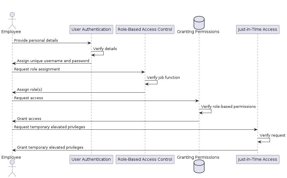
Figure 8-9. [caption]
Let’s put this all together.
Employees are given a unique username and password to authenticate themselves when accessing the company’s cloud-hosted resources or SaaS applications. [User Authentication]
The company defines roles such as “HR Manager,” “Finance Analyst,” and “Developer” to align with the different departments. These roles are associated with specific permissions and privileges based on the tasks and responsibilities of each role function. [Role-Based Access Control]
Employees who join the company are assigned to one or more roles based on their job function. For example, a new HR manager is assigned the “HR Manager” role, which grants them access to HR-related applications and data. [Granting Permissions]
In some instances, temporarily elevated privileges may be granted to users requiring additional access to specific tasks. For example, during system maintenance, the admin might temporarily receive elevated privileges to perform necessary updates. The company implements just-in-time access, where additional privileges beyond the standard role-based permissions are granted temporarily and only when needed. [Just-in-Time Access]
The company also conducts periodic access reviews to ensure user permissions are up-to-date and aligned with their current roles and responsibilities. Any unnecessary privileges are promptly revoked to minimize the attack surface and maintain the principle of least privilege. [Regular Access Reviews]
The authentication process is designed to provide granular control over access and minimize the trust placed on users and devices. By continuously verifying identities, evaluating context, and enforcing access policies, zero-trust networks enhance security by reducing the potential attack surface and minimizing the impact of potential breaches.
Cloud Access Security Brokers (CASBs) and Identity federation
Cloud Access Security Brokers (CASBs) provide an additional layer of security when accessing cloud resources. CASBs are usually deployed as a cloud-based proxy between the organization’s network and the provider, providing visibility and monitoring of all traffic transiting to and from the cloud. Some of the capabilities of a cloud access security broker include, but are not limited to:
-
Data Loss Prevention (DLP), preventing data leakage via the cloud by detecting and blocking sensitive information
-
Threat Detection and Remediation, monitoring for malicious activity such as malware, ransomware, phishing attacks, etc., and taking action to prevent the threat from spreading
-
Encryption & Data Integrity, ensuring that internal data is encrypted in transit and at rest and that data integrity is maintained
-
Enforcing authentication policies, such as multi-factor authentication (MFA) and role-based access control (RBAC), making it harder for attackers to gain unauthorized access to an organization’s resources
In addition to the discussed capabilities, CASBs can also apply and maintain network security policies like access control lists (ACLs) and network segmentation. They also offer monitoring and logging functions that enable organizations to detect suspicious or potentially harmful activity.
Identity federation is yet another key component of establishing trust for cloud traffic. Federated identity services like SAML and OAuth are important tools for establishing trust as they allow organizations to establish single sign-on (SSO) capabilities across multiple cloud applications.
By limiting resources to verified users, the risk of unauthorized access can be significantly reduced.
Filtering
Filtering is the process by which packets are admitted or rejected by systems on a network. When most people think of filtering, they typically envision a firewall, a service or device which sits between the network and application to filter traffic going to or coming from that device. Firewalls do provide filtering, but they can provide other services like network address translation (NAT), traffic shaping, and VPN tunnel services. Filtering can be provided by other systems not traditionally considered, like routers or managed switches. It’s important to remember that filtering is a simple service which can be applied at many points in a networked system.
Filtering can be quite frustrating for users without a security mindset since it blocks desired network communication. Wouldn’t it be better to get rid of that nuisance and assume the user knows what they want? Unfortunately, well-meaning users can trivially expose services that on further inspection they would rather not expose. During the early days of always-on internet connections, users’ computers routinely made the accident of exposing file sharing and chat services on the public internet.
Filtering provides a type of checks and balances for network communication, forcing users to consider whether a particular connection should really cross a sensitive boundary.
Many of the zero trust concepts so far have focused on advanced encryption and authentication systems. This is because these aspects of network security are not nearly as pervasive in network designs as they should be. However, we should not downplay the importance of network filtering. It is still a critical component of a zero trust architecture, and so we will explore it in three parts:
Host filtering
Filtering of traffic at the host
Bookended filtering
Filtering of traffic by a peer host in the network
Intermediary filtering
Filtering of traffic by devices in between two hosts
Host Filtering
Host filtering deputizes a network endpoint to be an active participant in its own security. The goal is to ensure that every host is configured to filter its own network traffic. This is different than traditional network design, where filtering is delegated to a centralized system away from the host.
Centralized filtering is most often implemented using a hardware firewall. These firewalls make use of application-specific integrated circuits (ASICs) to efficiently process packets flowing through the device. Since the device is often a shared resource for many backend systems, these ASICs are critical for it to accomplish the task of filtering the aggregate traffic of all those systems. Using ASICs brings raw performance at the expense of flexibility.
Software firewalls, like those found in modern operating systems, are much more flexible than their hardware counterparts. They offer a rich set of services like defining policies based on time of day and arbitrary offset value. Many of these software firewalls can be further extended with new modules to offer additional services. Unlike the early days of the internet, all modern desktop and server operating systems now offer some form of network filtering via a host-based firewall:
- Linux
-
IPtables
- BSD systems
-
Berkley Packet Filter (BPF)
- macOS
-
Application firewall and additional host firewalls available via the command line
- Windows
-
Windows Firewall service
Perhaps surprisingly, neither iOS or Android ships with a host-based firewall. Apple’s iOS Security Guide notes that it considers a firewall unnecessary since the attack surface area is reduced on iOS “by limiting listening ports and removing unnecessary network utilities such as telnet, shells, or a web server.” Google does not publish an official security guide. Android, perhaps owing to its ability to run non- Play Store approved software, does have third-party firewalls available to install if a user chooses to do so.
Zero trust systems assume the network is hostile. As a result, they filter network traffic at every point possible, often using on-host firewalls. Adding an on-host firewall reduces the attack surface of a host by filtering out undesirable network traffic. While software-based firewalls don’t have the same throughput capabilities as hardware based systems, the fact that the filtering is distributed across the system (and therefore sees a portion of the aggregate traffic) often results in little performance degradation in practice.
Using on-host filtering is simple to get started with. Configuration management systems have very good support for managing on-host firewalls. When writing the logic to install services, it’s easiest to capture the allowed connections right alongside its installation and configuration routines. Filtering in a remote system, conversely, is more difficult since the exceptions are separated from the application that needs them.
On-host firewalls also offer opportunities for novel uses of programmable filtering. Single packet authorization (SPA), which we discussed earlier in this chapter, is a great example of this idea. SPA programmatically manages the on-host firewall to reduce the attack surface of a service on a host. This is advantageous because on occasion, carefully crafted malicious packets can be constructed to exploit a weakness in network services. For example, a service might require authentication and authorization before processing a request, but the authentication logic could have a buffer overflow error which an attacker can use to implement a remote code execution vulnerability. By introducing a filtering layer, we can hide the more complex service interface behind a simpler system which manages firewall rules.
There are of course issues when using on-host firewalls exclusively for network filtering. One such issue is the chance for a co-located firewall to be rendered meaningless should a host become compromised. An attacker who is able to gain access to a host and elevate their privilege could remove the on-host firewall or adjust its configuration. Needless to say, this is a big deal, as it removes a layer of defense in the system. This concern is why filtering has traditionally been handled by a separate device, away from potentially risky hosts.
This approach highlights the benefits of isolation in security design, which on-host filtering could benefit from. As the industry moves toward isolation techniques like virtualization and containerization, it becomes clear that these technologies present an opportunity to further isolate on-host filtering. Without these technologies, the only form of isolation that is available is local user privilege. On a Unix-based system, for example, only the root user is able to make adjustments to the firewall configuration. In a virtualized system, however, one could implement filtering outside the virtual machine, which provides strong guarantees against attacks on the filtering system. In fact, this is how Amazon’s security group feature is implemented, as shown in Figure 8-10.
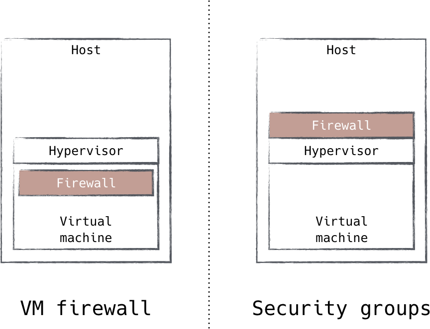
Figure 8-10. EC2 Security Groups move filtering outside the virtual machine to improve isolation
Another issue with on-host filtering is the cost associated with pushing filtering deep into the network. Imagine a scenario where a large percentage of traffic is filtered away by on-host filtering. By applying filtering nearest to the destination system, the network incurs extra cost to transmit those packets, only for them to be ultimately thrown away. This situation also raises the possibility of a denial-of-service attack forcing internal network infrastructure to route large volumes of useless traffic, as well as overwhelming the comparatively weaker software firewalls. For this reason, while on-host firewalls are the best place to start thinking about filtering, they present a risk if they are the only place filtering occurs. We will discuss ways to push filtering out into the network in “Intermediary Filtering” on page XX [173].
Bookended Filtering
Bookended filtering is the act of applying policy not just on the receipt of a packet, but while sending them too. This mode of filtering is not commonly found in traditional networks. It brings some interesting advantages to network design, which we will now explore.
Egress (the opposite of ingress) is a term used to describe network traffic that is leaving a host. This type of filtering is commonly used to manage communication from a private network out to public networks, but it is rarely used within a private network. There are a few reasons this is the case:
-
Ingress filtering is easier to reason about, since listening services can be enumerated when building firewall rules. Egress filtering requires more bookkeeping to capture how hosts intend to communicate.
-
Ingress filtering is generally considered good enough to stop undesirable communication in the network.
-
Egress filtering requires knowledge of every expected flow, something not usually found in traditional networks.
Bookended filtering uses egress filtering within the zero trust network to further harden the system. We can see how this hardening is beneficial with the example shown in Figure 8-11. Let’s consider a system where a database server has ingress filter rules set up to allow access from application servers. A well-meaning administrator is investigating some network connectivity issues. In the process of their investigation, the admin loosens the database’s ingress filtering to rule out the possibility that it was causing the issue. Crucially, this administrator forgets to revert their change after disproving that theory. This error removes a layer of defense in the system for some time. Worse yet, discovering this lost defense can be difficult because the expected communication (from the app servers to the database server) continues to work.
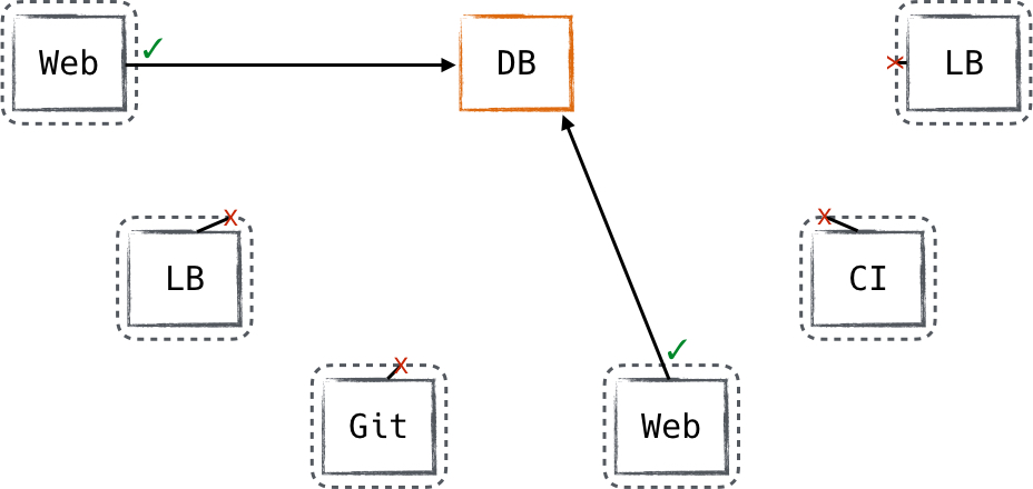
Figure 8-11. Bookended filtering can provide protection in unexpected circumstances
In this scenario, a network that has pervasive bookended filtering is protected even when this critical misconfiguration is in the system. In a way, it’s similar to herd immunity—the collective benefit that a community provides to unvaccinated members when the vast majority of members are vaccinated against a disease. Instead of preventing illness, bookended filtering protects misconfigured systems from the potential impact of that misconfiguration.
Building bookended filtering into a system isn’t as hard as it might seem, given the right conditions. Communication flows need to be captured in a way that can be consumed programmatically. The best way to capture these flows is by defining fine grained ingress rules. These ingress rules should allow access to a service based on each client’s server role instead of broadly opening access to a service. By capturing this detail, we have constructed a dependency graph from which egress rules can be calculated and applied throughout the system.
Like we discussed in host filtering, egress filtering is best applied when it is isolated from the applications running within the system. The same insights apply here: prefer implementing filtering on the other side of a virtualized or containerized environment to have the most robust filtering mechanisms. Looking beyond the filtering implementation, it’s important to consider the isolation of the data used to build egress filtering rules. It might seem attractive to calculate that data from a dynamic data source such as a service discovery system, but bookended filtering is most effective when the flow database is isolated from the running system. Instead use a slowly changing database, especially one that requires a human to review changes.
Intermediary Filtering
Intermediary filtering is the idea that devices other than the sender or receiver can and should participate in filtering traffic in a zero trust network. This at a minimum means perimeter filtering can play a role in a zero trust network, and at the maximum, intermediary devices within the network’s fabric.
As we discussed in “Host Filtering” on page [XX], filtering traffic only at the destination incurs an extra cost on the network when the ratio of undesirable traffic is very high. High throughput filtered traffic will most often originate from internet ingress traffic. Ideally, we want to filter traffic as soon as possible to reduce the impact and the cost of filtering. For this application, filtering at the perimeter systems that sit between the zero trust network and the internet is ideal. These devices typically need to be hardware based to efficiently filter the packets coming into the system. Perimeter filters can also be an important check and balance in a zero trust network. The perimeter filters should be a combination of global rules and coarse-grained host policy. By keeping global rules separate from host policy, invariants about the external network configuration are defined.
Exceptions to this policy should be traceable back to host infrastructure that relies on those exceptions, and the actions taken to instantiate them. The best implementation derives these exceptions from the host policies themselves. By tying the host policy to the exception policy, the system will be more consistent as hosts come and go from the network. These exceptions, however, must be verified to be as narrowly scoped as possible. A review process should be exercised for all policy changes in order to guard against overly broad exceptions which can compromise the system’s security.
UPnP Considered Harmful
Deriving perimeter policies from host policies should not be conflated with UPnP, a technology used to reconfigure consumer firewalls. UPnP is rightly criticized because any application on the network can reconfigure the perimeter. In the zero trust model, there is a chain of trust between the host policies and the exceptions that are created at the perimeter.
It might seem odd that we’re discussing perimeter filtering in such a positive light, given the failings of the perimeter model. The key detail to understand here is that zero trust networks don’t throw out all perimeter concepts. Instead, they encourage administrators to start at the host and work their way outward. Perimeter devices eventually play a role in this way, with denial-of-service mitigation being by far the most notable application.
An exciting idea in zero trust networks is to use the host policy database to dynamically program the network fabric itself. This would result in a software-defined network (SDN) that does not blindly route packets to the destination, but actively manages switching and routing policy based on which flows are expected and allowed. This results in a couple of benefits:
-
Potentially malicious traffic is kept away from hosts, reducing the attack surface.
-
Software firewalls on the hosts are augmented by the network itself, adding additional layers of defense in the network.
Like the perimeter filtering discussed earlier, filtering in the network fabric should be seen as an enhancement to the base layer of host-based filtering. It must not act as a replacement for it.
Summary
This chapter focused on how traffic gains trust in a zero trust network. We teased apart the distinctions between encryption and authenticity—two concepts that are related but distinct. Zero trust networks require authenticity in communication, and most networks also gain value in having their traffic encrypted.
We explored the first packet problem in network communications. Modern authentication systems are fairly complicated systems, which results in a large surface area for attacks. We talked about hiding those services behind a single packet authorization system, which is a relatively simple service that can be used to hide a more complex authentication system like TLS.
We then talked about two competing protocols for encryption and authentication of network traffic: TLS and IPsec. We discussed how these systems differ and gave clear guidance that mutually authenticated TLS is best suited for client/server interactions or in heterogeneous environments, while IPsec seems well suited inside the datacenter (particularly so when Network Address Translation is not present).
We also covered cloud traffic and the fact that cloud-based services present additional challenges to trusting traffic. We talked about some of the challenges, leveraging authentication and authorization mechanisms for cloud-based flows, and cloud native security tools to apply access control policies and enforce the principles of least privilege.
Zero trust networks still need packet filtering capabilities, which they deploy throughout the network. We described three types of filtering that can be deployed in such a network: host, bookended, and intermediary filtering. Each type of filtering adds additional robustness to the network and can be deployed in the network using system automation and a shared database of expected network communication.
The next chapter takes all the concepts we have learned thus far and lays out a plan for creating your own zero trust network.
1 https://www.cipherdyne.org/fwknop/