There is a tradition in the world of programming for the first program you write to display the words "Hello World!" on the screen. In keeping with tradition, I'm going to show you how to create a simple version of this program for SPOT. This will allow me to demonstrate one of the simplest blocks included with the NXT software—the DISPLAY block. Once you've taken care of tradition, I'll show you the rest of the DISPLAY block's features.
In Chapter 2, I explained to you the concept of pseudo-code. Let me now give some pseudo-code to SPOT:
SPOT, I'd like you to display the words "Hello World!" on your LCD screen.
Pseudo-code doesn't get much simpler than this. All I want SPOT to do for now is put the words "Hello World!" on his LCD screen. To convert this pseudo-code to an NXT-G program, I'm going to use the DISPLAY block.
Let's start by launching the NXT software and entering HelloWorld in the Create New Program text box (see Figure 3-1). Click the Go button, and the HelloWorld program is open and ready.
Note
Many of the figures used in this book show screens from version 1.0 of the NXT-G retail version of the software. In some instances, the figures are from version 2.0 of the retail software. If you're like me, you're going to have a hard time spotting the differences. In most cases, the workspace, buttons, menus, and other tools are identical between versions. Where the differences are substantial, I'll include images from both versions. In either case, when something is specific to either version 1.0 or version 2.0, I'll let you know. In most cases, however, the differences are so minor that you shouldn't have any difficulty understanding the figures, no matter which version of the software you are using.
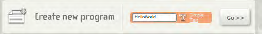
Figure 3-2 shows the new program opened (see the tab called HelloWorld in the upper left corner?) and ready for you to start dropping NXT-G blocks. The word "Start" appears on the work space beam, telling you where your first programming block will be placed.
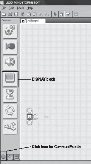
Are you ready for this? I want you to click the DISPLAY block on the Common Palette and hold down the mouse button. Drag and drop the block on the beam where it says "Start" (see Figure 3-3).
Note
If you don't see the Common Palette along the left side of the screen, click on the green dot indicated in Figure 3-2.
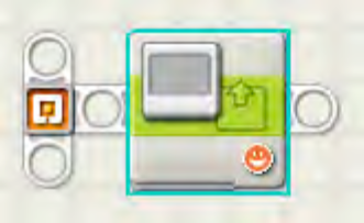
Anytime you drop a block on the work space, the block's configuration panel will be displayed in the lower left corner of the screen. The configuration panel is where you will be doing most of the programming work for your robots. The configuration panel is similar to a car's dashboard. In a car, you can tune to a specific radio station, turn on the windshield wipers, and even find out the car's speed from the speedometer. The configuration panel allows you to turn on and off certain things as well as receive feedback. For example, you can use the DISPLAY block's configuration panel to choose what to put on the LCD screen, but the DISPLAY block can also receive input from items outside your control, just like your car can display a warning light on the dashboard when you need to check the oil or fill up on gasoline. Figure 3-4 shows the configuration panel for the DISPLAY block you just dropped on to the work space. To see the configuration panel for any block that you've dropped into your program, simply click that block using the Pointer tool, and an aqua-colored band will appear around the block that is selected.
Note
If you select multiple blocks, no configuration panel will be displayed.
Now, to have SPOT's LCD screen display the words "Hello World!", make sure you've first selected the DISPLAY block (click it with the Pointer tool).
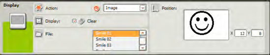
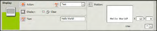
As you can see in Figure 3-4, by default, the DISPLAY block's Action section has a drop-down menu with the Image option selected (there are four options: Image, Text, Drawing, or Reset). Click the drop-down menu, and select Text from the options listed. You will now see a text box with the words "Mindstorms NXT" inside. Change the text to Hello World!, and you'll see the same text displayed in the Position section's preview box on the right side of the configuration panel (see Figure 3-5).
Now, using the File menu, select Save, and use the Browse button to choose a location to save the file on your computer. Click the Save button when you are finished. After saving, connect SPOT to your computer, and upload the HelloWorld program. (If you're not familiar with how to upload a program, consult the Help documentation. Ideally, however, you should have worked through all the Robo Center or Robo Educator projects to familiarize yourself with this function.)
Note
For the remaining chapters in the book, you'll need to remember to save your programs. I won't keep bugging you with instructions to save your programs and upload them to your robots, OK? Just get in a habit of saving often.
After the program is uploaded, select it from the File section, and press the orange button (also called the Enter button) on the Brick to run the program.
Did you see it? The program probably ran so quickly that you didn't even see the text displayed! Why does this happen? Well, when the program runs it is supposed to write "Hello World!" to the LCD screen and then end. And that's exactly what happened—the text displays, and the program ends. This happens so fast that you don't even get to see the text displayed. The good news is that this is very easy to fix, so let me update the pseudo-code before I continue:
SPOT, I'd like you to display the words "Hello World" on your LCD screen for 10 seconds.
There are numerous ways to keep the text on the screen until you have a chance to read it, but I'm only going to show you one method in this chapter. You'll discover other methods as you continue with the book.
To fix this problem, I'd like you to move the mouse pointer over the WAIT block icon on the Common Palette. When you do this, a collection of WAIT blocks will appear on a fly-out menu, as shown in Figure 3-6.
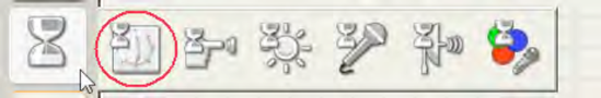
The WAIT block does exactly what it says—it waits. As you can see in Figure 3-6, there are many different types of WAIT blocks, but the one I'm interested in right now is the WAIT block that allows me to specify how many seconds to wait. That would be the TIME WAIT block (the block that is circled on the fly-out menu in Figure 3-6).
Note
For users of the 1.0 version of NXT-G, you won't see the WAIT icon to the far right in Figure 3-6. That WAIT block is for the Color sensor that is included with the 2.0 Retail set.
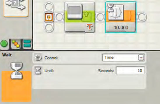
Select the icon for the WAIT TIME block, and place it immediately after the DISPLAY block. In the configuration panel for the WAIT TIME block, select a reasonable time for the text to be displayed—my pseudo-code asked SPOT to wait for 10 seconds, so that is what I will configure (see Figure 3-7).
Now run the program. You should see the text "Hello World!" display on the LCD screen for 10 seconds before the program ends.
You're probably thinking what I'm thinking, "That wasn't that exciting." But remember this: with programming, you have to start somewhere. And, in a few simple steps, you've now figured out how to add text to the LCD screen for any robot you build in the future. Now, let's look at some of the other things you can do with the DISPLAY block.
Note
Every program block has its own unique settings, so each configuration panel is different. Sections for the DISPLAY block, for example, include Action, Display, File, Text, Type, and Position. Sometimes, a section will not be visible until other options are selected. Don't let this worry you; I'll be going over all the unique items for each block throughout the book.
The Display section only has one configurable item—a Clear checkbox. When this box is checked (and the block is executed in a program), the Brick's LCD screen will be cleared of any text or images that are currently on the screen. After the screen is cleared, the DISPLAY block will put what you configured on the screen.
If you leave the box unchecked, any text or graphics you configure the DISPLAY block to put on the LCD will display on the screen along with whatever is currently displayed, instead of replacing it.
This is useful when you want text to appear on multiple lines; you can use multiple DISPLAY blocks to keep adding text to make sentences and even paragraphs. Without clearing the screen, you can create your own simple images using the Drawing option in the Action section, which I'll explain next.
With the Action section, you have four options in the drop-down menu: Image, Text, Drawing, and Reset. By default, the drop-down menu is set to Image for a new DISPLAY block placed on the work space.
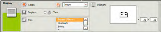
When you select Image in the drop-down menu, the File section is displayed; this section gives you access to a collection of small built-in pictures that can be displayed on the LCD screen (see Figure 3-8).
Note
Version 2.0 of the Retail software now comes with an Image Editor that allows you to make your own images! I'll cover this feature in Appendix C.
By clicking and holding the image in the preview pane on the right side of the configuration panel, you can drag the image around the small pane and place it wherever you wish. You can also use the X and Y coordinates to type in numbers that will place the image at a location of your choosing (see Appendix A for a brief explanation of the X/Y coordinate system if you're unfamiliar with it). You can use this ability to move the image around the preview pane to place multiple images (which require using additional DISPLAY blocks) on the LCD screen.
The next option in the Action drop-down menu is Text. You've already used this in the previous "Hello World!" example, but I'd like to add that you also have the ability to drag the text around the preview pane and place it in a particular location. The LCD screen is broken into eight horizontal lines; you can use the small drop-down box next to the Preview pane to choose a number between 1 and 8 to define the line where text is placed.
The third option in the Action drop-down menu is Drawing (see Figure 3-9). You can choose to draw a line or a circle or to place a single point on the LCD screen, so your artistic talents will be somewhat limited. To create a detailed drawing, you would have to place dozens or more DISPLAY blocks one after the other, and the combination of lines, circles, and points would create the image. A better solution (for owners of the 2.0 retail software) is to use the built-in Image Editor that I cover in Appendix C. But the Drawing options are available to 1.0 and 2.0 software owners and are useful for drawing boxes around other text on the screen, so keep that in mind.
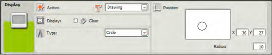
To use the Drawing tool, select Point, Line, or Circle from the Type section (this section only appears if you have selected Drawing in the Action drop-down menu). For the point, you can drag it around the Preview pane and place it anywhere. You can also use the X and Y coordinates to place the point more accurately.
For owners of the 1.0 version of the software, if you choose the Line, the end point of the Line is at position 10,10 (in the lower left corner). Click anywhere in the Preview pane to draw a line from that point to the place where you clicked. You can change the end point (10,10) by entering new coordinates in the X and Y boxes. You can also type in X and Y coordinates for the other end of the line for more accurate control over it.
For 2.0 owners, the Line tool works similarly. A line is added automatically—simply click anywhere in the Preview pane and the line will be redrawn with one of its ends terminating on the spot you clicked. Likewise, you can use the X and Y boxes to manually select a starting point for the line as well as use the End Point X and Y boxes to manually enter an ending point for the line.
Finally, for the circle, you have the option of changing the radius of the circle by typing the number in the Radius text box. Drag the circle around the Preview pane to place it properly. Use the X and Y boxes to manually enter the center point of the circle.
The final option in the Action drop-down menu, Reset, is useful when you would like to clear the LCD screen of any items. The default NXT screen (which shows the name of the program currently running) will appear on the LCD screen.
Before closing out this chapter on the DISPLAY block, I want to cover one additional item briefly: data hubs (this topic will be covered in more detail in Chapter 7). Most programming blocks come with what's called a "data hub." Take a look at Figure 3-10.
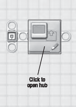
If you click the bottom-left edge of a block, this section will drop down and reveal the data hub (see Figure 3-11). Click the section again, and the data hub will close. It might take some practice to find the correct place to click, so try it a few times until you get used to opening and closing the data hub.
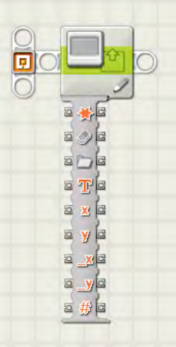
What is this data hub? The data hub allows you to draw data wires from one block to another using data plugs. Data wires and plugs will be covered in much more detail in Chapter 7, but for now, all you really need to know is that wires can connect blocks to share data. Data plugs are places on the block where you will connect wires. So there will be a data plug on one block with a wire going out and another data plug on a different block with a wire coming in. Data wires can carry information such as text, numbers, and other values. Remember all those items you could configure in the DISPLAY block? Well, items such as the text displayed or the radius of a circle can all be configured without using the configuration panel. Instead, you can draw data wires from one block's plugs into plugs on another block. I'll cover this topic in more detail later in the book (in Chapter 7), but right now, I just want you to take a look at Figure 3-12, so I can give you a preview of what's to come.
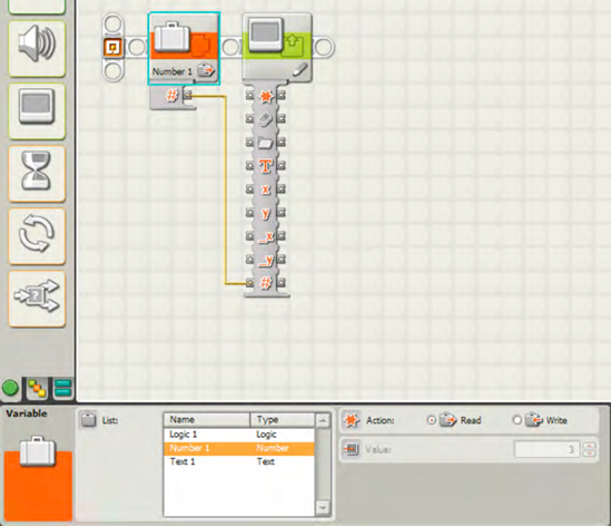
In Figure 3-12, I've placed a VARIABLE block in front of the DISPLAY block. I cover the VARIABLE block in Chapter 18, but for now, all you really need to know is that this type of block can hold text, a number, or what's called a logic value (either True or False). In this example, I've configured the VARIABLE block to hold a number: 3.
Now, here's where it gets fun. Remember that when you draw a circle you can specify the radius of the circle in the configuration panel? Well, this VARIABLE block has only one plug in its data hub. For this block, it's holding the value of 3. I click that plug and draw a line into the last plug of the DISPLAY block's data hub. That last plug corresponds to the radius of a drawn circle (hover your mouse pointer over a plug, and it will tell you what it is). When I drag the wire out of the VARIABLE block plug and into the DISPLAY block plug, the line becomes solid yellow, and I know I've correctly configured the DISPLAY block.
Note
Plugs on the left side of a block's data hub are known as input plugs. Plugs on the right side of the block's data hub are called output plugs.
If the line is dotted, it tells me I've incorrectly connected two plugs. This can happen for many reasons. For example, if I had put text into the VARIABLE block and dragged the wire into the DISPLAY block's Radius plug, I would get a dotted line. This happens because the Radius plug expects a number value to be coming out of the VARIABLE block, not text.
As I mentioned earlier, I'll cover data plugs in more detail in Chapter 7. Before you begin using these data wires for more advanced programming, however, you need to understand the basics of the programming blocks.
Now it's time to get some more practice with the DISPLAY and WAIT TIME blocks that you learned about in this chapter. Below are two exercises for creating new NXT-G programs for SPOT. (If you get stuck, the answers are at the end of this chapter.)
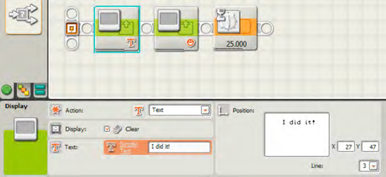
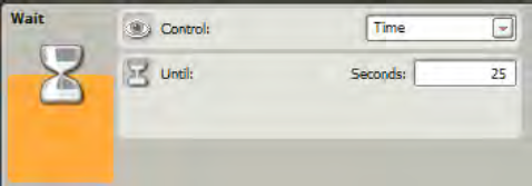
For this exercise, I'd like you to modify the HelloWorld program. For this program, I want you to enter one line of text near the top of the LCD screen, a picture (your choice) below the text, and have both items displayed for 25 seconds before the program ends.
Tip
Keeping both the text and the picture on the screen at the same time requires a special option to be deselected.
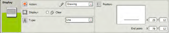
Use four DISPLAY blocks to manually draw a rectangle (or make it more challenging and draw a square) to the LCD screen. After a side of the square is drawn, have the robot pause for 5 seconds before drawing the next side. When the square is completed, have the robot pause for 10 seconds before the program ends.
Tip
Read Appendix A for help with the coordinate system and the starting and end points of each line.
Spot needs to get moving! It's a little dull just watching him sit on the floor, so let's continue learning about blocks in Chapter 4 by giving him somewhere to go. You'll learn all about doing this with the MOVE block.
Following are some possible exercise solutions. Remember, your solutions may be somewhat different. Results are what matter. Very often, there is more than one way to get to the same end result.
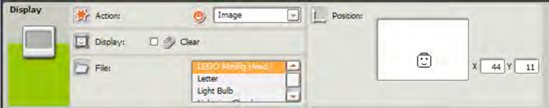
Figure 3-13 shows the program for one possible solution. Figure 3-13 also shows the configuration panel for the first of the three program blocks. Figures 3-14 and 3-15 show the panels for the other two blocks. Notice that the second DISPLAY block (from the left) has its Clear box unchecked (Figure 3-14). Unchecking that box will keep the words "I did it!" on the LCD screen while the image is also displayed. If the Clear box remains checked, the text will be erased and only the image will be displayed.
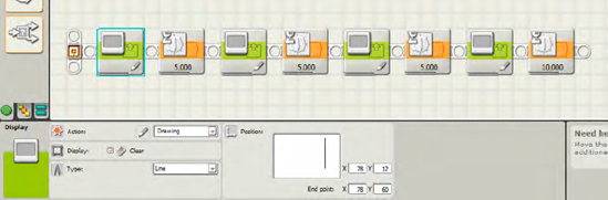
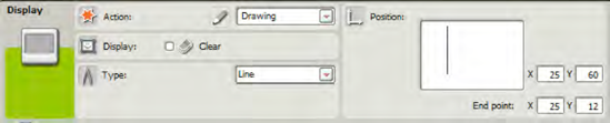
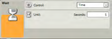
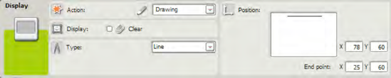
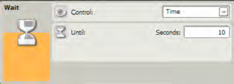
Figures 3-16 through 3-23 show the eight configuration panels for the eight blocks used in the program I wrote as my own solution to Exercise 3-2. Figure 3-16 shows the panel for the first block. Figures 3-17 through 3-23 show the panels for subsequent blocks.
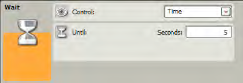
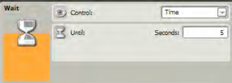
Notice that the first three WAIT TIME blocks (Figures 3-17, 3-19, Figure 3-21) are all configured for 5 seconds; only the last WAIT TIME block (Figure 3-23) is set for 10 seconds. Do you see how the coordinates are manually entered to make the lines all match up perfectly? Try to modify the coordinates to draw a perfect square. Also, remember that the Clear checkbox must be unchecked for the last three DISPLAY blocks (but not the first).