
p.941
7_______________________
Meeting the requirements of the Building Regulations – Buildings other than dwellings
7.0.1 How to use this chapter
This chapter has been designed to help you meet the requirements of the Building Regulations in buildings other than dwelling houses. It follows the same format as Chapter 6 and we have adopted the foundations-up approach putting all the relevant Approved Document requirements that relate to each specific area in buildings other than dwellings into each section of this Chapter.
We described the requirements for ‘Dwellings’ in Chapter 6 and, as a high percentage of the requirements, information and explanations about Building Regulations for dwellings is also applicable to buildings other than dwellings, we have decided that this chapter will only include information specific to non-dwellings. To assist the reader further we have used the same sub-chapter heading in both chapters (e.g. 6.1 and 7.1 are both entitled ‘Foundations’).
When using Chapter 7, you will be advised to refer back to Chapter 6 to see if there are any general purpose requirements or information for your project that they should take account of. Three Approved Documents, B2 (Fire safety), L2A /L2B (Conservation of fuel and power) and M2 (Access to and use of buildings) apply specifically to buildings other than dwellings. Approved Documents P (Electrical Safety) and Q (Security) only apply to dwellings.

p.942
For your assistance (and to avoid you having to constantly refer back), where tables and figures are common for a number of sections we have deliberately duplicated them in each section. We have also used the following symbols to draw attention to certain areas.
• Information in the shaded box is either a paraphrase of the requirement or the requirement itself. |
A 0.2a |
• Each separate row contains a paragraph of the Approved Document as a separate bullet. |
|
|
|
|
A.3 |
7.1.1 Requirements
This section provides the details for buildings other than dwellings only where they differ from the requirements already given in Chapter 6.1.
p.943

![]() Note: Approved Documents B2 (Fire Safety Volume 2) and L2A (Conservation of fuel and power) relate specifically to buildings other than dwellings.
Note: Approved Documents B2 (Fire Safety Volume 2) and L2A (Conservation of fuel and power) relate specifically to buildings other than dwellings.
7.1.2 Meeting the requirement
Basic requirements for stability, site preparation and rainwater drainage are the same as for dwellings and these are contained in Chapter 6.1.
7.1.2.1 Structure
7.1.2.1.1 Small single-storey non-residential buildings
• As shown in Figure 7.1.1, in a small single-storey non-residential buildings the: |
A 2C4b |
![]() height (H) should be less than 3m
height (H) should be less than 3m
![]() width (W) should be less than 9m (the greatest length or width of the building).
width (W) should be less than 9m (the greatest length or width of the building).
p.944

Figure 7.1.1 Proportion and size of small single-storey non-residential buildings
![]() Authors’ note: These dimensions are subject to the limits maximum heights of buildings given in Chapter 6.1 Table 6.1.1 and Figure 6.1.2, which correlate to various site exposure conditions and wind speeds.
Authors’ note: These dimensions are subject to the limits maximum heights of buildings given in Chapter 6.1 Table 6.1.1 and Figure 6.1.2, which correlate to various site exposure conditions and wind speeds.
7.1.2.2 Fire safety
7.1.2.2.1 Portal frames
Portal frames are often used in single-storey industrial and commercial buildings where there is no need for the structure to be fire resistant. This requirement does need not be followed if the building is fitted with a sprinkler system.
The foundation and its connection to the portal frame should transmit any overturning moment while allowing the external wall to continue to perform its structural function. |
B2 12.4 |
7.1.2.3 Conservation of fuel and power
7.1.2.3.1 Swimming pool basins
• The U-value of the basin in a swimming pool (the walls and floor) should be a minimum of 0.25W/m2K (calculated in accordance with BS EN ISO 133705). |
L2B 4.14 |
• The effects of insulation boards not being fully supported or point loading should be considered. |
|
• Thermal bridging around basin wall and floor junctions with foundations should be avoided. |
p.945
In buildings other than dwellings, more sophisticated automatic control systems such as occupancy sensors (using local passive infrared detectors) or indoor carbon dioxide concentration sensors (using electronic carbon dioxide detectors) can be used as an indicator of occupancy level and, therefore, body odour.
7.2.1 Requirements
This section provides the details for buildings other than dwellings only where they differ from the requirements already given in Chapter 6.2.

p.946

![]() Note:
Note:
1. Approved Document B2 (Fire safety) and L2A and L2B (Conservation of fuel and power) apply specifically to buildings other than dwellings.
2. The Workplace (Health, Safety and Welfare) Regulations 1992 apply to most places where people work.
p.947
7.2.2 Meeting the requirement
7.2.2.1 Fire safety
7.2.2.1.1 Air circulation systems in flats with a protected stairway or entrance hall
• If an air circulation system circulates air only within an individual flat with an internal protected stairway or entrance hall: |
B2 2.18 |
|
|
|
|
|
|
|
|
|
|
• A ducted warm air heating system thermostat should be mounted on the living room wall (between 1370mm and 1830mm); its maximum setting should not exceed 27°C. |
7.2.2.1.2 Small single-stair buildings
• Every flat in small single-stair building does not need access to alternative escape routes if: |
B2 2.21 |
|
|
|
|
|
p.948
7.2.2.1.3 Smoke control of common escape routes
• In buildings (other than small ones) the corridor adjoining a stair should have a vent, and: |
B2 2.26 |
|
|
|
|
|
|
• In single-stair buildings smoke vents on the fire floor and at the head of the stair should be actuated by smoke detectors in the common access space. |
|
• In buildings with more than one stair the smoke vents may be actuated manually. |
|
|
|
|
|
• Vents should either: |
|
|
|
|
|
|
|
|
|
|
|
|
|
|
|
|
|
|
|
|
|
|
p.949
• Guidance on mechanical ventilation is available in BS EN 12101-6. |
B2 2.27 |
• If the stair serves an enclosed car park, or place of special fire hazard, lobbies or corridors should have 0.4m2 permanent ventilation or a mechanical smoke-control system. |
B2 2.47 |
• A protected lobby should have not less than 0.4m2 permanent ventilation or have a mechanical smoke-control system. |
B2 4.35 |
7.2.2.1.4 Mechanical ventilation and air-conditioning systems
• Ductwork in mechanical ventilation systems should not transfer fire and smoke through the building. |
|
• Exhaust points should be sited away from final exits, combustible building cladding or roofing materials and openings into the building. |
B2 5.46 |
• Ventilation ducts supplying or extracting air directly to or from a protected escape route should not serve other areas. |
|
• A separate ventilation system should be provided for each protected stairway. |
|
• Where the ductwork system serves more than one part of a subdivided escape route, a fire damper should be provided where ductwork enters each section of the escape route operated by a smoke detector or suitable fire detection system. |
|
• Fire dampers should close when smoke is detected. |
B2 5.47 |
• Ducts passing through the enclosure of a protected escape route should be fire-resisting. |
B2 5.48 |
• Smoke detectors should be fitted in the extract ductwork of a system which recirculates air before the point of separation of the recirculated air and the air to be discharged to the open air and before any filters or other air cleaning equipment. Such detector(s) should: |
B2 5.49 |
|
|
|
|
• Non-domestic kitchens, car parks and plant rooms should have separate and independent extraction systems and the extracted air should not be recirculated. |
B2 5.50 |
• Guidance on the use of mechanical ventilation in a place of assembly is in BS 5588-6. |
B2 5.51 |
• Where a pressure differential system is installed, ventilation and air-conditioning systems in the building should be compatible with it when operating under fire conditions. |
B2 5.52 |
• BS 5720 provides guidance on the design and installation of mechanical ventilation and air-conditioning plant. Guidance on the provision of smoke detectors in ventilation ductwork can be found in BS 5839-1. |
B2 5.53 |
• Rooms containing refuse chutes, or provided for the storage of refuse, should be approached either directly from the open air or by way of a protected lobby provided with not less than 0.2m2 of permanent ventilation. |
B2 5.56 |
p.950
7.2.2.1.5 Openings in compartment walls or in compartment floors
• Ventilation ducts may pass through openings in compartment walls or compartment floors. |
B2 8.34 |
• If ventilation duct passes through or is built into a compartment wall or compartment floor each wall of the duct should have a fire resistance of at least half that of the wall or floor. |
B2 10.16 |
• Any shaft passing directly from one compartment to another should be enclosed in a protected shaft. |
B2 8.35 |
• The construction enclosing a protected shaft (see Figure 7.2.1) should: |
|
|
|
|
|
|
B2 8.37 |
• If a protected shaft contains a stair and/or a lift, it should not also contain a pipe conveying oil (other than in the mechanism of a hydraulic lift) or contain a ventilating duct (other than a duct that ventilates or pressurizes the stairway to keep it smoke free). |
B2 8.40 |
• A protected shaft for piped flammable gas should be ventilated direct to the outside air by ventilation openings at high and low level in the shaft. |
|
• Any extension of a storey floor into a ventilation shaft should not compromise the free movement of air over the entire length of the shaft. |
|
• Guidance on such shafts is in BS 8313. |
B2 8.41 |
• Where air handling ducts pass through fire-separating elements the integrity of those elements should be maintained. |
|
• There are three basic methods of protection: |
|
|
|
|
|
|
|
|
|
|
B2 10.9 |
• Guidance on the design and installation of mechanical ventilation and air-conditioning plant is in BS 5720 and on ventilation and air-conditioning ductwork in BS 5588-9. |
B2 10.14 |
p.951
7.2.2.1.6 Car parks and shopping complexes
• There is a low probability of fire spread between storeys if the car park is well ventilated. |
|
• There are three ventilation methods: |
|
|
B2 11.2b |
|
|
|
B2 11.5 |
|
|
|
|
|
|
|
|
|
|
|
|
|
|
|
|
|
B2 11.6 |
p.952

Figure 7.2.1 Protected shafts
p.953
7.2.2.1.7 Canopies
• Some canopy structures are exempt from the Building Regulations by falling within Class 6 or Class 7 of Schedule 2 to the Regulations (Exempt Buildings and Works). |
B2 13.11 |
• Canopies that do not meet the exemption criteria may find the provisions in Approved Document B2 on limits of unprotected areas onerous. |
|
• Where a canopy is attached to the side of a building, provided that the edges of the canopy are at least 2m from the relevant boundary, the separation distance may be determined from the wall rather than the edge of the canopy. |
|
• In view of the high degree of ventilation and heat dissipation achieved by the open-sided construction of a free-standing canopy structure above a limited risk or controlled hazard (e.g. over petrol pumps), and provided the canopy is 1000mm or more from the relevant boundary, the provisions for space separation could be disregarded. |
p.954
7.2.2.1.8 Provision of information
p.955
• For most buildings, basic information on the location of fire protection measures should be provided showing any smoke-control system(s) (or ventilation system with a smoke-control function), including mode of operation and control systems. |
B2 App G.2g |
p.956
7.2.2.2 Ventilation
7.2.2.2.1 Assumptions used in applying performance criteria for offices
• The pollutant(s) of most importance will vary between building types (e.g. dwelling, office, factory), building uses (e.g. industrial process, shop, commercial kitchen), and from room to room within a building (e.g. kitchen, shower room, conference room, photocopier room). |
F 4.10 |
• In an office building, body odour is often the key pollutant, but there are a number of other pollutant sources including the building itself, furnishings, printers and photocopiers. |
|
• Offices are assumed to have an air permeability of 3m3/ (h.m2) at 50 Pa. |
F App A |
• In large buildings (low ratio of surface area to volume contained), infiltration can be assumed to be negligible compared with the purpose provided ventilation. |
|
• The ventilation effectiveness is 0.9. |
|
• The total outdoor air supply rate for offices is 10 l/s per person. |
|
|
|
|
|
• During the heating season, the surface water activity in a room should not exceed: |
|
|
|
|
|
|
|
• Pollutants from office equipment (ozone and organic compounds) require an extract rate of 20 l/s per machine during use. |
|
• Extract rates for sanitary accommodation are the same as for dwellings. |
|
• Extract rates for food and beverage preparation areas are the same as dwellings. |
|
• It is simpler to remove high concentrations of pollutants from office spaces than from dwellings (e.g. leaving rooms unoccupied until acceptable pollutant levels are achieved). |
p.957
7.2.2.2.2 New buildings other than dwellings
• The following guidance is for the range of building types and uses below: |
F 6.1 |
|
|
|
|
|
|
• The ventilation provisions will not necessarily meet cooling needs. |
F 6.2 |
• Fresh air supplies should be protected from contaminants injurious to health. |
|
• Guidance on the siting of air inlets is provided in Appendix D to Approved Document F. |
F 6.3 |
• Guidance on design measures to avoid legionella contamination, including design features not related to the ventilation of the building, is given in the HSE document Legionnaires’ Disease: The Control of Legionella Bacteria in Water Systems. |
|
• Further guidance may be found in CIBSE TM13 Minimising the Risk of Legionnaires’ Disease and in BSRIA Application Guides AG19/2000, AG20/2000 and AG21/2000. |
F 6.4 |
p.958
• Guidance on recirculated air in air-conditioning and mechanical ventilation systems is given in HSE document L24 Workplace Health, Safety and Welfare, Workplace (Health, Safety and Welfare) Regulations 1992, Approved Code of Practice and guidance. |
F 6.5 |
• Adequate space should be provided in a central plant room for the maintenance of the plant. |
|
• Where no special provision is required, the requirement could be satisfied if 600mm space is provided where access is required between plant and 1100mm where space for routine cleaning is required. |
|
• Additional space may be needed for access doors, withdrawal of filters, etc. |
|
• Guidance for complex situations is in Defence Works Functional Standard, Design and Maintenance Guide 08: Space Requirements for Plant Access Operation and Maintenance. |
|
• Guidance for the cleaning of ducts is provided by CIBSE Ventilation Hygiene Toolkit and HVCA TR/19 – Guide to good practice: Internal Cleanliness of Ventilation Systems. |
F 6.7 |
• There are four ways to comply with the ventilation requirements of the Building Regulations: |
|
|
|
|
|
|
|
|
F 6.8 F 6.9-6.16 |
• Ventilation should provide the air flow rates set out in paragraphs 6.10 to 6.13 (below). |
|
• The air flow rates specified in this Approved Document are for the installed performance. |
F 6.9 |
• Extract to outside is required in all office sanitary accommodation, washrooms and food and beverage preparation areas. |
|
• Printers and photocopiers in substantial use (greater than 30 minutes per hour) should be located in a separate room with extract provision. |
|
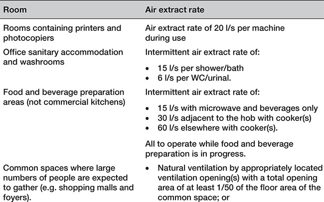
• The extract flow rates should be no less than those specified in Table 7.2.1. |
F 6.10 |
p.959
Table 7.2.1 Extract ventilation rates
p.960

![]() Authors’ note: Table 6.3 of Approved Document F contains extensive details of Regulations and guidance for other buildings and spaces.
Authors’ note: Table 6.3 of Approved Document F contains extensive details of Regulations and guidance for other buildings and spaces.
• The total outdoor air supply rate for offices is 10 l/s per person. |
F 6.11 |
• Purge ventilation is required in each office. |
|
• The total ventilation should be sufficient to reduce pollutants to an acceptable level before the space is occupied. |
|
• The purged air should be taken directly to outside and should not be recirculated to any other part of the building. |
F 6.12 |
• The outdoor air supply rates for offices is based on controlling body odours with low levels of other pollutants. |
|
• Where there are significant levels of other pollutants, adequate outdoor air supply can be achieved by following the calculation method provided in CIBSE Guide A. |
F 6.13 |
• The air flow rates specified in the Approved Document can be provided by a mainly natural ventilation system by following the following guidance: |
|
|
|
|
|
|
|
|
|
|
|
|
|
|
|
|
|
F 6.14 |
|
|
|
|
|
|
|
• A wide range of natural ventilation systems for providing whole building ventilation is given in CIBSE Application Manual AM 10: Natural ventilation in non-domestic buildings. |
|
• The requirement will be satisfied by following: |
|
|
|
F 6.15 |
• An alternative approach can be satisfied by following the recommendations of: |
|
|
|
|
F 6.16 |
• The Workplace (Health, Safety and Welfare) Regulations 1992 apply to most places where people work. |
|
• A short guide, INDG244, is available from the HSE. |
F 6.17 |
p.961
7.2.2.2.3 Car parks
• Enclosed-type and multistorey car parks should have ventilation equipment that limits the carbon monoxide to: |
|
|
|
|
F 6.18 |
• The following would also satisfy the requirement: |
|
|
|
|
|
|
|
|
F 6.20 |
• Further guidance can be found in Code of practice for ground floor, multistorey and underground car parks published by the Association for Petroleum and Explosives Administration (www.apea.org.uk); CIBSE Guide B Section 2.3.23.3. |
F 6.21 |
p.962
7.2.2.3 Conservation of fuel and power
7.2.2.3.1 Controls
• Systems should have controls to enable the achievement of reasonable standards of energy efficiency in use. |
L1A 2.43 |
• Ventilation and air-conditioning system control: |
|
|
|
|
|
|
|
• Central plant should operate only as and when the zone systems require it. The default condition should be off. |
|
• In a naturally ventilated building, this is NOT evidence that the internal environment of the building will be satisfactory. |
L2A 2.52 |
• Central ventilation specific fan power should be 1.8 l/s. |
|
• Demand control (mechanical ventilation) should permit variable speed control of fans via CO2 sensors. |
L2A Table 5 |
• Roof ventilators should have a U-value of 3.5 W/m2K. |
L2A Table 3 L2B Table 3 |
p.963
7.2.2.3.2 Testing
• The approved procedure for pressure testing is given in the Air Tightness Testing and Measurement Association (ATTMA) publication Measuring Air Permeability of Building Envelopes. |
L2A Table 3.9 |
• The preferred test method is that trickle ventilators should be temporarily sealed rather than just closed. |
|
• Building Control Bodies (BCBs) should be provided with evidence that test equipment has been calibrated within the previous 12 months using a UKAS-accredited facility. |
|
• When an incoming occupier does first fit-out work on all or part of the building through the provision or extension of any of the fixed services for mechanical ventilation, then TER/BER submission should be made to the BCB after completion to demonstrate compliance for the part of the building covered by the fit-out work. |
L2A 2.35 |
• In a ventilation system, the replacement of any part which is not a combustion appliance (such as valve or pump) or the addition of an output device or the addition of a control device is not notifiable. |
|
• The work will be notifiable whenever commissioning is possible and necessary to enable a reasonable use of fuel and power. |
L2B 3.30a |
• The installation of a stand-alone, self-contained ventilation service which consists of a single appliance and any associated controls (as long as |
L2B 3.30a |
• they are not connected to any other fixed building service) are non-notifiable, e.g. a mechanical extractor fan in a kitchen or bathroom. |
|
• If a ventilation appliance is installed in a room containing a natural draught open-flued combustion appliance or service, such as a gas fire which uses a chimney as its flue, it will be notifiable. |
|
• Where the work involves the provision or extension of a mechanical ventilation service then the guidance set out in the Non-Domestic Building Services Compliance Guide. The Guide should be followed. |
L2B 4.29 |
p.964
7.3.1 Requirements
This section provides the details for buildings other than dwellings only where they differ from the requirements already given in Chapter 6.3.


![]() Note: Approved Document B2 (Fire safety) applies specifically to buildings other than dwellings.
Note: Approved Document B2 (Fire safety) applies specifically to buildings other than dwellings.
p.965
7.3.2 Meeting the requirement
7.3.2.1 Fire safety
7.3.2.1.1 Openings for pipes
• Pipes which pass through a fire-separating element (unless the pipe is in a protected shaft), should meet the appropriate provisions in alternatives A, B or C below. |
B2 10.5 |
• Alternative A. Provide a proprietary sealing system which maintains the fire resistance of the wall, floor or cavity barrier. |
B2 10.6 |
• Alternative B. Where a proprietary sealing system is not used, fire-stopping may be used around the pipe, keeping the opening as small as possible (the nominal internal diameters of the pipe are given in Table 7.3.1). |
B2 10.7 |
• Alternative C. A pipe of lead, aluminium, aluminium alloy, fibre-cement or uPVC, with a maximum nominal internal diameter of 160mm, may be used with a sleeving of non-combustible pipe as shown in Figure 7.3.1. The specification for non-combustible and uPVC pipes is given in the notes to Table 7.3.1. |
B2 10.8 |
p.966
Table 7.3.1 Maximum nominal internal diameter of pipes passing through compartment walls


Figure 7.3.1 Pipes penetrating structure
p.967
7.3.2.1.2 Fire-stopping
p.968
• Enclosures for drainage and water supply pipes should: |
B2 Diagram 38 |
|
|
|
|
|
|
|
|
• The casing should: |
|
|
|
|
|
|
|
• The opening for a pipe should be as small as possible and fire-stopped around the pipe (see Figure 7.3.2) |
|
• Casing around a drainage system should have an integrity of 30 minutes. |
B2 Able A1 |
p.969

Figure 7.3.2 Enclosure for drainage and water supply pipes
p.970
7.3.2.2 Access to and use of buildings
7.4.1 Requirements
This section provides the details for buildings other than dwellings only where they differ from the requirements already given in Chapter 6.4.

![]() Note:
Note:
1. Approved Document B2 (Fire safety) applies specifically to buildings other than dwellings.
2. Approved Document Q (Security) only applies to dwellings.
p.971
7.4.2 Meeting the requirement
7.4.2.1 Fire safety
7.4.2.1.1 Automatic fire detection and fire alarm systems
p.972
• A fire detection system may be required in an unoccupied part of the premises (e.g. a basement). |
B2 1.36c |
p.973
7.4.2.1.2 Means of escape
• Where the basement storey contains a habitable room, either an external door or window suitable for egress from the basement or protected stairway leading to a final exit should be provided. |
B2 2.6 |
• Special measures should be taken to prevent a basement fire endangering upper storeys. |
B2 2.43 |
• An escape stair that forms part of the only escape route from an upper storey of a building it should not serve any basement storey. |
|
• The basement should be served by a separate stair. |
B2 2.44 |
• If there is more than one escape stair from an upper storey of a building only one of the stairs needs to terminate at ground level. |
|
• Stairs may connect with the basement storey(s) if there is a protected lobby or corridor between the stair(s) and accommodation at each basement level. |
B2 2.45 |
• In the case of small shop, office, industrial or other premises with no storey larger than 280m2 and no more than two storeys plus a basement storey), the guidance in paragraph 3.323 should be followed. |
B2 3.1 |
p.974
• In covered shopping complexes with premises in single occupancy no storey should have a floor area greater than 280m2 |
|
• The premises should not comprise more than a basement, a ground floor and a first storey. |
B2 3.33 |
![]() Note: The distance of travel in small premises with an open stairway is measured to the foot of the stair in a basement or to the head of the stair in a first storey.
Note: The distance of travel in small premises with an open stairway is measured to the foot of the stair in a basement or to the head of the stair in a first storey.
• The maximum distance of travel between basement of first storey in small premises with a protected stair is 18m. |
B2 Table 5 |
• A single escape stair is permitted from a basement. |
B2 4.5a |
• The width of an exit route from a stair which also forms the escape from the ground/basement storeys may need to be increased in accordance with the escape route. |
B2 4.17 |
• Escape based on simultaneous evacuation should be used for all stairs serving basements. |
B2 4.23 |
• Table 7.4.1 shows the capacity of stairs for basements and for simultaneous evacuation of the building. |
p.975
Table 7.4.1 Capacity of a stair for basements and simultaneous evacuation of the building

p.976
7.5.1 Requirements
This section provides the details for buildings other than dwellings only where they differ from the requirements already given in Chapter 6.5.


![]() Note:
Note:
1. Approved Documents B2 (Fire safety), L2A and L2B (Conservation of fuel and power) and M2 (Access to and use of buildings) apply specifically to buildings other than dwellings.
2. Approved Document M4(3) (Access to and use of buildings Volume 1: Dwellings) is an optional requirement for wheelchair-user dwellings.
p.977
7.5.2 Meeting the requirement
7.5.2.1 Structure
• In small single-storey non-residential buildings and annexes, the floor area of the building or annex should not exceed 36m². |
A 2C38a |
• Where the floor area of the building or annexe exceeds 10m², the walls should have a mass of not less than 130kg/m². |
|
• There is no surface mass limitation recommended for floor areas of 10m² or less. |
A 2C38c |
• Provide effective horizontal ties or effective anchorage of suspended floors in the following buildings: |
|
|
|
|
|
|
|
|
|
|
|
|
|
|
A2 5.1c |
p.978
7.5.2.2 Fire safety
7.5.2.2.1 General
• A building containing an atrium passing through compartment floors may need special fire safety measures. |
|
• Guidance on suitable fire safety measures in these circumstances are in BS 5588-7. |
B2 0.28 |
• A fire detection and fire alarm system should be installed in all new habitable rooms above the ground floor level, or in ground floor rooms where there is no final exit from the new room. |
B2 1.6 |
• Smoke alarms should not be fixed over a stair or any other opening between floors. |
B2 1.15 |
• The means of escape from a flat with a floor not more than 4.5m above ground level is relatively simple to provide. |
B2 2.1 |
p.979
7.5.2.2.2 Escape routes
• A gallery should be provided with an alternative exit or, if the gallery floor is not more than 4.5m above ground level, an emergency egress should be provided. |
|
• Where the gallery floor is not provided with an alternative exit or escape window, it should comply with the following: |
|
|
|
|
|
|
|
|
|
|
|
|
B2 2.8 |
• The bottom of the openable area of any window provided for emergency egress should be not more than 1100mm above the floor. |
B2 2.9 |
p.980

Figure 7.5.1 Gallery floors with no alternative exit
• In a flat which has a floor at more than 4.5m above ground level one of the following approaches should be taken: |
|
|
B2 2.13 |
|
|
|
|
• In a multistorey flat that does not have its own external entrance at ground level but has a floor at more than 4.5m above ground level, one of the following approaches should be taken: |
|
|
|
|
B2 2.16 |
p.981

Figure 7.5.2 Multistorey flat exits
|
|
|
p.982
• Transfer grilles should not be fitted in any floor enclosing a protected stairway or entrance hall. |
B2 2.18 |
• A single protected stair may be used, provided that the top floor of the building is no more than 11m above ground level and a high-level openable vent for fire and rescue service use is provided at each floor level. |
B2 2.21 B2 4.5b |
• In single-stair buildings, the smoke vents on the fire floor and at the head of the stair should be actuated by means of smoke detectors in the common access space providing access to the flats. |
B2 2.26 |
• On detection of smoke in the common corridor/lobby, the vent(s) on the fire floor, the vent at the top of the smoke shaft and to the stairway should all open simultaneously. |
|
• If a building has a single access stair, that stair may be external if it serves a floor not more than 6m above ground level. |
B2 2.48 B2 2.49 |
• A single route is acceptable for parts of a floor from which a storey exit can be reached within the travel distance limit for travel in one direction set in Table 7.5.1. |
B2 3.5a |
p.983
• When the number of occupants likely to use a room, tier or storey is not known, the capacity should be calculated on the basis of the appropriate floor space factors. |
B2 3.8 |
• Escape routes should not be prejudiced by openings between floors, such as an escalator. |
B2 3.12 |
p.984
Table 7.5.1 Limitations on travel distance

• Where a ground floor storey exit shares a final exit with a stair via a ground floor lobby, the width of the final exit should be sufficient to enable a maximum evacuation flow rate equal to or greater than that from the storey exit and stair combined. |
|
• Where the number of people entering the lobby from the ground floor is more than 60 then the distance from the foot of the stair, or the storey exit, to the final exit should be a minimum of 2m. |
B2 3.23 |
• Corridor partitions should be carried up to the soffit of the structural floor above, or to a suspended ceiling. |
B2 3.25 |
p.985
7.5.2.2.3 Small premises
• In covered shopping complexes, the size of small units that may be served by a single exit is further restricted (BS 5588-10). |
|
• The premises should be in a single occupancy and should not comprise more than a basement, a ground floor and a first storey. |
|
• No storey should have a floor area greater than 280m2 (see Figure 7.5.3). |
B2 3.33 |
p.986

Figure 7.5.3 Maximum travel distance in small premises with single stairs
• The floor areas should be generally undivided (except for kitchens, ancillary offices and stores) to ensure that exits are clearly visible from all parts of the floor areas. |
B2 3.34 |
• Clear glazed areas should be provided in any partitioning separating a kitchen or ancillary office from an open floor area. |
B2 3.36 |
p.987
7.5.2.2.4 Care homes

p.988
p.989
7.5.2.2.5 External escape routes
• Where the maximum number of people who will use an escape stairs is unknown, the occupant capacity should be calculated on the basis of the appropriate floor space factors. |
B2 4.19 B2 App C |
• The escape stairs in a building designed for simultaneous evacuation should have the capacity to allow all floors to be evacuated simultaneously. |
B2 4.22 |
• In phased evacuation, the first to be evacuated are all those of reduced mobility and those on the storey most immediately affected by the fire. |
|
• If there is a need to evacuate more people, it is done two floors at a time. |
B2 4.26 |
• In a building designed on the basis of phased evacuation: |
|
|
|
|
B2 4.29c |
• The minimum width of stair needed for phased evacuation is given in Section 7.10. |
|
• This assumes a phased evacuation of the fire floor first followed by evacuation of not more than two floors at a time. |
B2 4.30 |
• Additional measures may be required if a protected stairway is also a protected shaft and it penetrates one or more compartment floors. |
B2 4.32 |
• A stair in small premises may be open if it is a single stair if the floor area in any storey is less than 90m2. |
B2 4.33 |
• All doors on escape routes should have a swing that is clear of any change of floor level. |
B2 5.15 |
• Every escape stair flight and landing that serves a floor level more than 18m above ground should be constructed of materials of limited combustibility. |
B2 5.19 |
• The floorings of all escape routes (including the treads of steps and surfaces of ramps and landings) should be chosen to minimize their slipperiness when wet. |
B2 5.27 |
• Any sloping floor should have a maximum pitch of 35° to the horizontal. |
B2 5.28 |
• Lift entrances should be separated from the floor area on every storey by a protected lobby. |
B2 5.42 |
p.990
7.5.2.2.6 Floor linings
• The upper surfaces of floors and stairs are not significantly involved in a fire until well developed and thus do not play an important part in fire spread in the early stages of a fire. |
B2 ii |
• Parts of walls in rooms may be of a poorer performance than specified in the Approved Document provided the total area of those parts in any one room does not exceed one half of the floor area of the room; and subject to a maximum of 20m2 in residential accommodation and 60m2 in non-residential accommodation. |
B2 6.4 |
• A suspended ceiling can contribute to the overall fire resistance of a floor/ceiling assembly. |
B2 6.5 |
• Cavity barriers are needed in some concealed floor or roof spaces. |
B2 6.6 |
p.991
7.5.2.2.7 Elements of structure
• Elements of structure such as floor and gallery structures, should have at least the fire resistance given in Appendix A, Table A1. |
B2 7.2 |
• The following floors are excluded from the definition of an element of structure: |
|
|
|
|
|
|
|
|
B2 7.4 |
• The normal provisions for fire resistance of elements of structure may be onerous if applied to the raised free-standing floors (such as those supported by racking). |
B2 7.7 |
• A structure which does not have the appropriate fire resistance is acceptable provided the following conditions are satisfied: |
|
• the structure has only one tier and is used for storage purposes only |
|
|
|
|
|
|
B2 7.8 |
|
|
• Where an existing building is converted into flats, and has timber floors which are to be retained, the relevant provisions for fire resistance may be difficult to meet. |
B2 7.9 |
![]() Note: Where the lower level is provided with an automatic detection and alarm system that complies with BS 5839-1 then the floor size may be increased to not more than 20m in either width or length. Where the building is fitted throughout with an automatic sprinkler system, there are no limits on the size of the floor.
Note: Where the lower level is provided with an automatic detection and alarm system that complies with BS 5839-1 then the floor size may be increased to not more than 20m in either width or length. Where the building is fitted throughout with an automatic sprinkler system, there are no limits on the size of the floor.
p.992
Table 7.5.2 Specific provisions of test for fire resistance of elements of structure – floors

Table 7.5.3 Minimum periods of fire resistance – floors


p.993
7.5.2.2.8 Compartmentation
• The spread of fire within a building can be restricted by compartmentation using walls and/or floors of fire-resisting construction. |
B2 8.1 |
• The appropriate degree of subdivision depends on the height to the floor of the top storey in the building. |
B2 8.2 |
• Subdivision is achieved using compartment walls and compartment floors. |
B2 8.3 |
• Any floors bounding a protected shaft are considered to be compartment floors. |
B2 8.7 |
• Parts of a building that are occupied mainly for different purposes should be separated from one another by compartment walls and/or compartment floors. |
|
• This does not apply where one of the different purposes is ancillary to the other. |
B2 8.11 |
• Any floors in a place of special fire hazard should be a compartment floor. |
B2 8.12 |
• In buildings containing flats, every floor should be a compartment floor. |
B2 8.13 |
• Blocks of flats with a floor more than 30m above ground level should be fitted with a sprinkler system. |
B2 8.14 |
• All floors in institutional buildings including healthcare should be constructed as compartment floors. |
B2 8.15 |
• All floors in other residential buildings should be constructed as compartment floors. |
B2 8.17 |
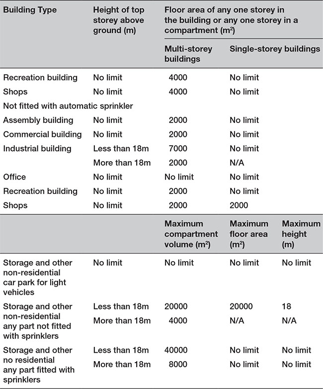
• The following should be constructed as compartment floors in non-residential buildings (i.e. office, shop and commercial, assembly and recreation, industrial, storage): |
|
|
|
|
|
|
|
|
|
|
B2 8.18 |
p.994
Table 7.5.4 Maximum dimensions of building or compartment (non-residential buildings)

• Every compartment floor should form a complete barrier to fire between the compartments they separate. |
|
• Every compartment floor should have the appropriate fire resistance shown in Table 7.5.3 and 7.5.4. |
B2 8.20 |
p.995

Figure 7.5.4 Compartment floors
p.996
• Adjoining buildings should only be separated by walls, not floors. |
B2 8.21 |
• Where a compartment floor meets another compartment wall or an external wall, the junction should maintain the fire resistance of the compartmentation. |
|
• Fire-stopping should meet the provisions of paragraphs 10.17 to 10.19 of Approved Document B2. |
B2 8.25 |
• At the junction of a compartment floor with an external wall that has no fire resistance the external wall should be restrained at floor level to reduce the movement of the wall away from the floor when exposed to fire. |
B2 8.26 |
• Compartment walls should be able to accommodate the predicted deflection of the floor above by either: |
|
|
|
|
B2 8.27 |
• Openings in compartment floors should be limited to those for: |
|
|
|
|
|
|
|
|
|
|
B2 8.34 |
• Any extension of a storey floor into a protected shaft should not compromise the free movement of air over the entire length of the shaft. |
B2 8.41 |
• Cavity barriers should be provided at the junction between an external cavity wall and every compartment floor. |
|
• Cavity barriers should be provided at the junction between an internal cavity wall and every compartment floor. |
B2 9.3 |
• The maximum dimensions of cavities do not apply to the cavities described below: |
|
|
|
|
B2 9.10 |
• Where any single room with a ceiling cavity or underfloor service void exceeds the dimensions given in Table 7.5.5, cavity barriers should be provided on the line of the enclosing walls/ partitions of that room. |
B2 9.11 |
p.997
Table 7.5.5 Maximum dimensions of cavities in non-domestic buildings – any other cavity

p.998
7.5.2.2.9 Pipes
• Pipes which pass through a fire-separating element should have a proprietary sealing system which has been shown by test to maintain the fire resistance of the floor. |
|
• Where sealing is not used then the nominal diameter of a pipe should conform with the requirements for dwellings in 6.5.2. |
B2 10.6 |
• Enclosures for drains or water supply pipes should be bounded by a compartment floor, an outside wall, an intermediate floor, or a casing. |
B2 Diagram 38 |
• If a flue or duct passes through a compartment floor each wall of the flue or duct should have a fire resistance of at least half that of the floor in order to prevent the bypassing of the compartmentation. |
B2 10.16 |
p.999
7.5.2.2.10 Car parks
• In open-sided car park,s each storey should be naturally ventilated by permanent openings at each car parking level, having an aggregate vent area not less than 1/20 of the floor area at that level, of which at least half (1/40) should be equally provided between two opposing walls. |
|
• Any surface finish applied to a floor of the car park need not be non-combustible. |
B2 11.3 |
• Car parks that are not open sided may have some, more limited, natural ventilation. Each storey should be ventilated by permanent openings which have an aggregate free vent area not less than 1/40 of the floor area at that level, of which at least half should be split equally and provided between two opposing walls (1/160 on each side). |
B2 11.5 |
p.1000
7.5.2.2.11 Fire service provision
• Wet fire mains should be provided in buildings with a floor at more than 50m above fire and rescue service vehicle access level. |
|
• In lower buildings where fire mains are provided, either wet or dry mains are suitable. |
B2 15.6 |
• Buildings with a floor at more than 18m above fire and rescue service vehicle access level, or with a basement at more than 10m below fire and rescue service vehicle access level, should be provided with firefighting shafts containing firefighting lifts (see Figure 7.5.5). |
B2 17.2 |
• Smoke outlets, connected directly to the open air, should be provided from every basement storey, except for any basement storey that has: |
|
|
|
|
B2 18.4 |
p.1001
• The combined clear cross-sectional area of all smoke outlets should not be less than 1/40 of the floor area of the storey they serve. |
B2 18.8 |
• The amount of combustible material per unit of floor area will affect the standard of fire resistance specified. |
|
• The height of the top floor above ground will affect the ease of escape and of firefighting operations and the consequences should large scale collapse occur. |
B2 App A.4 |
• Most elements of structure in a single-storey building may not need fire resistance. However, fire resistance will be needed if the element: |
B2 App A.21d |
|
|
|
|
|

Figure 7.5.5 Provision of firefighting shafts
p.1002
7.5.2.3 Conservation of fuel and power
• The Target CO2 Emission Rate (TER) is the minimum energy performance requirement for a new building and is expressed in terms of the mass of CO2 emitted per year per square metre of the total useful floor area of the building. |
L2A 2.2 |
• The limiting standard for the properties of a floor is 0.25W/m2K. |
L2A 2.39 |
• Buildings with a total useful floor area greater than 1000m2 should have automatic energy meter reading and data collection facilities. |
L2A 2.47c L2B 4.35b |
• Buildings with less than 500m2 total useful floor area are exempt from the requirement to be pressure tested. |
L2A 3.12a |
• A factory-made modular building of less than 500m2 floor area, with a planned service life of more than two years at more than one location, and where no site assembly work is needed other than making linkages between standard modules using standard link details, is exempt from the requirement to be pressure tested. |
L2A 3.12b |
• The concurrent notional U-value for a floor is 0.22W/m2K whether side-lit, top-lit or unlit. |
L2A Table 5 |
• Stand-alone buildings other than dwellings with a total useful floor area of less than 50m2 are exempt from the energy efficiency requirements. |
L2B 3.5d |
• Conservatories or porches at ground level, where the floor area is less than 30m2, are exempt from the energy efficiency requirements. |
L2B 3.21 |
• Where a proposed extension has a total useful floor area that is both greater than 100m2, and greater than 25 percent of the total useful floor area of the existing building, the work should be regarded as a new building and the guidance in Approved Document L2A followed. |
p.1003
• The requirement for consequential improvements, if appropriate, should also be met by following the guidance in Section 6 of Approved Document L2B. |
L2B 4.2 |
• Where a swimming pool is provided in a building, the U-value of the basin (walls and floor) should be no worse than 0.25W/m2K, as calculated according to BS EN ISO 133705. |
|
• Care should be taken to avoid thermal bridging, particularly around basin wall and floor junctions with foundations. |
L2B 4.14 |
• Where controlled services or fittings are being provided or extended if the area of openings in the newly created building is more than 25 percent of the total floor area, the area of openings should either be reduced to be not greater than 25 percent, or the larger area should be compensated for in some other way. |
L2B 4.19a |
• Work on fixed internal lighting is not notifiable if the floor area that is to be provided with new fixed lighting is not greater than 100m2. |
|
• The work should still meet the standards set out in the compliance guide. |
L2B 4.29d |
• The U-value for new floors is 0.22W/m2K. |
L2B Table 4 |
• When upgrading thermal elements of floors: |
|
|
|
|
L2B 5.13 |
7.5.2.4 Access to and use of buildings
7.5.2.4.1 Surfaces
• Internal floor surfaces adjacent to the threshold of an accessible entrance should be made of materials that do not impede the movement of wheelchairs, e.g. not coir matting. |
|
• Changes in floor materials in accessible entrance should not create a potential trip hazard. |
|
• Where mat wells are provided, the surface of the mat should be level with the surface of the adjacent floor finish. |
M2 2.7 M2 2.29 |
• The floor surface in an entrance lobby should help to remove rainwater from shoes and wheelchairs. |
M2 2.29f |
• Any manual controls for powered door systems should be located between 750mm and 1000mm above floor level. |
M2 2.21g |
• Any reception desk or counter should be designed to accommodate both standing and seated visitors such that |
M2 3.6e |
p.1004
• at least one section of the counter is at least 1500mm wide, with its surface no higher than 760mm, and there is a knee recess, not less than 700mm, above floor level. |
|
• The floor surface in an entrance hall or reception area should be slip resistant. |
M2 3.6g |
• In order to help people with visual impairment to appreciate the size of a space they have entered, or to find their way around, there should be a visual contrast between the wall and the ceiling, and between the wall and the floor. |
M2 3.12 |
• In corridors: |
|
|
|
|
|
|
|
|
|
|
M2 3.14 |
• Junctions of floor surface materials at the entrance to the lobby area should not create a potential trip hazard. |
M2 3.16e |
p.1005
Table 7.5.6 Limits for ramp gradient


Figure 7.5.6 Relationship of ramp gradient to the going of a flight
7.5.2.4.2 Refreshment facilities
• In refreshment facilities, bars and counters all floor areas, even when located at different levels, should be accessible. |
M2 4.3 |
• In refreshment facilities, changes in floor level are acceptable provided the different levels are accessible. |
M2 4.15 |
• Part of the working surface of a bar or serving counter should be permanently accessible to wheelchair users, and at a level of not more than 850mm above the floor and, where necessary, part at a higher level for people standing. |
M2 4.16b |
• The worktop of a shared refreshment facility (e.g. for tea making) should be at 850mm above the floor with a clear space beneath at least 700mm above the floor (see Figure 7.5.7). |
M2 4.16c |
• A wheelchair-accessible threshold should be located at the transition between an external seating area and the interior of the facility. |
M2 4.16d |

Figure 7.5.7 Example of a shared refreshment facility
p.1006
7.5.2.4.3 Lifting devices, lifts and stair lifts
• In lifting devices and platforms: |
|
|
|
|
M2 3.28 M2 3.43 |
• In passenger lifts: |
|
|
|
|
M2 3.34 |
• People using or waiting for a lifting platform should have audible and visual information to tell them that the platform has arrived, and which floor it has reached. |
M2 3.37 |
7.5.2.4.4 Conference and working facilities
• In audience and spectator facilities the floor of each wheelchair space should be horizontal. |
M2 4.12h |
• Wheelchair spaces at the back of a stepped terraced floor are provided in accordance with Figure 7.5.8 or 7.5.9 (the latter is best suited to entertainment buildings, such as cinemas). |
M 4.12k |
• In lecture/conference facilities, wheelchair users should have access to a podium or stage by means of a ramp or lifting platform. |
|
• There are exceptions to height requirements for some outlets, e.g. those set into the floor in open-plan offices. |
M2 4.25 |
• Patterned walls in lecture/conference facilities, poor interior lighting or very bright natural backlighting should not have a detrimental effect on the ability of people to receive information from a sign language interpreter or a lip speaker. |
M2 4.9 |
p.1007

Figure 7.5.8 Possible location of wheelchair spaces in front of a rear aisle
p.1008

Figure 7.5.9 Example of a wheelchair space provision in a cinema or theatre
p.1009
7.5.2.4.4 Sleeping accommodation
• Where a balcony is provided in a wheelchair-accessible bedroom, the door should have a level threshold and no horizontal transoms between 900mm and 1200mm above the floor. |
4.24 |
• Wall-mounted socket outlets etc. should be between 400mm and 1000mm above the floor. |
|
• Switches for permanently wired appliances should be between 400mm and 1200mm above the floor, unless needed at a higher level for particular appliances. |
|
• Switches or controls that require precise hand movements should be between 750mm and 1200mm above the floor. |
|
• Simple push button controls should not be more than 1200mm above the floor. |
|
• Pull cords for emergency alarm systems should be set at 100mm and another set between 800mm and 1000mm above the floor. |
M2 4.30 |
• Floor, wall and ceiling surface materials should be chosen to help visually impaired people appreciate the boundaries of rooms or spaces and identify access routes. |
M2 4.32 |
• The surface finish of sanitary fittings and grab bars should contrast visually with background wall and floor finishes |
|
• There should be visual contrast between wall and floor finishes. |
M2 5.4k |
p.1010
7.6.1 Requirements
This section provides the details for buildings other than dwellings only where they differ from the requirements already given in Chapter 6.6.

p.1011

![]() Note:
Note:
1. Approved Documents B2 (Fire safety), L2A and L2B (Conservation of fuel and power) and M2 (Access to and use of buildings) apply specifically to buildings other than dwellings.
2. Approved Document P (Electrical Safety) only applies to dwellings.
p.1012
3. Approved Document (Physical infrastructure for high-speed electronic communications networks) applies to dwellings and buildings other than dwellings.
7.6.2 Meeting the requirement
7.6.2.1 Structure
• Where the wall cladding is more than the height of two risers (or 380mm if not part of a stair), or as a vehicle barrier, then account should be taken of the additional imposed loading, as stipulated in Approved Document K. |
A 3.5 |
• External, internal load bearing and parapet walls must extend to the full storey height. |
A 2C2 |
• Walls should comply with BS EN 1996-2 and BSI Published Document PD 6697. |
|
• If a requirement of this part is considered too onerous, in a particular case it may be possible for a minor departure to be made. |
|
|
|
• BS EN 1996-1-1 gives design strengths for walls where the suitability for use of masonry units of other compressive strengths is being considered. |
A 2C3a |
• The single leaf of external walls of small single-storey non-residential buildings and annexes need be only 90mm thick, notwithstanding paragraphs 2C38 of Approved Document A (summarized below). |
A 2C12 |
• Walls of small single-storey non-residential buildings and annexes should be solidly constructed in brickwork or blockwork. |
|
• Where the floor area of the building or annexe exceeds 10m² the walls should have a mass of not less than 130kg/m². |
A 2C38 |
• One or two major openings not more than 2.1m in height are permitted in one wall of the building or annexe only. |
|
• Walls should have a minimum thickness of 90mm. |
|
• Walls which do not contain a major opening but exceed 2.5m in length or height should be bonded or tied to piers for their full height at not more than 3m centres (Figure 7.6.1a). |
|
• Walls with one or two major openings should in addition have piers as shown in Figures 7.6.1b and 7.6.1c. |

Figure 7.6.1 Wall thickness
• Where ties are used to connect piers to walls they should be flat, 20mm x 3mm in cross section, in stainless steel, placed in pairs and be spaced at not more than 300mm centre vertically. |
A 2C38 |
• Walls should be tied horizontally at no more than 2m centres to the roof structure at eaves level, base of gables and along roof slopes as shown in Diagram 19 with straps fixed in accordance with paragraphs 2C35 and 2C36, summarized below. |
|
• Where straps cannot pass through a wall they should be adequately secured to the masonry using suitable fixings. |
|
• Wall ties should comply with BS EN 845-1 and should be material references 1 or 3 in BS EN 845-1 Table A1 austenitic stainless steel. |
A 2C19 |
• Walls should be properly bonded and solidly put together with mortar and constructed of masonry units conforming to: |
|
|
|
|
|
|
|
|
|
|
A 2C20 |

Figure 7.6.2 Lateral restraint at roof level
p.1013
7.6.2.2. Fire safety
7.6.2.1.1 General
• Smoke alarms/detectors should be mounted at least 300mm from walls. |
|
• Units designed for wall-mounting may also be used provided that the units are above the level of doorways opening into the space. |
B2 1.14 |
• Where an air circulation system circulates air only within an individual flat with an internal protected stairway or entrance hall, transfer grilles should not be fitted in any wall enclosing a protected stairway or entrance hall. |
B2 2.18 |
• The wall between each flat and the corridor should be a compartment wall. |
B2 2.24 |
• Smoke-control vents should be located on an external wall with minimum free area of 1.5m2. |
B2 2.26a |
• Storeys may be divided into two refuges by compartment wall. |
B2 Diagram20 |
• The choice of materials for walls and ceilings can significantly affect the spread of a fire and its rate of growth, even though they are not likely to be the materials first ignited. |
B2. i |
• Loadbearing walls and compartment walls are treated as elements of structure although the latter are not necessarily loadbearing. |
|
• External walls, such as curtain walls or other forms of cladding which transmit only self-weight and wind loads and do not transmit floor load, are not regarded as loadbearing. |
B2 B3.iii |
p.1014
7.6.2.1.2 Inner rooms
• The enclosures (walls or partitions) of an inner room should be stopped at least 500mm below the ceiling. |
|
• A suitably sited vision panel not less than 0.1m2 should be located in the door or wall of an inner room. |
B2 3.10 |
7.6.2.1.2 Care homes
• Progressive Horizontal Evacuation (PHE) in a care home requires those areas used for the care of residents to be subdivided into protected areas separated by compartment walls and compartment floors (see Figure 7.6.3) |
B2 3.41 B2 8.16 |
• Each storey, used for the care of residents, should be divided into at least three protected areas by compartment walls. |
B2 3.42 |
p.1015

Figure 7.6.3 Progressive Horizontal Evacuation (PHE) in care homes
p.1016
7.6.2.1.3 External escape routes
• Where an external escape route is beside an external wall of the building, that part of the external wall within 1800mm of the escape route should be of fire-resisting construction, up to a height of 1100mm above the paving level of the route. |
B2 3.30 |
• All walls, partitions and other enclosures that need to be fire-resisting to meet the provisions in this Approved Document (including roofs that form part of a means of escape) should have the appropriate performance given in Tables A1 and A2 of Appendix A. |
B2 5.3 |
• If a protected stairway projects beyond, or is recessed from, or is in an internal angle of, the adjoining external wall of the building then the distance between any unprotected area in the external enclosures to the building and any unprotected area in the enclosure to the stairway should be at least 1800mm (see Figure 7.6.4). |
B2 5.24 |
• Escape routes over flat roofs should be adequately defined and guarded by walls and/or protective barriers which meet the provisions in Approved Document K (Protection from falling, collision and impact). |
B2 5.35 |

Figure 7.6.4 External protection to external stairways
p.1017
7.6.2.1.3 Wall linings
• Surface linings of walls should meet the requirements of Table 7.6.1. |
|
• When a classification includes ‘s3, d2’, this means that there is no limit set for smoke production and/or flaming droplets/particles. |
B2 6.1 |
• Wall coverings which conform to BS EN 15102 (Decorative wallcoverings – roll and panel-form products), which achieve at least Class C-s3, d2 and are bonded to a Class A2-s3, d2 substrate, will also be acceptable. |
|
• For the purpose of the performance of wall linings, a wall includes: |
|
|
|
|
|
• A wall does not include: |
|
|
|
|
|
|
|
|
B2 6.2 |
• Parts of walls in rooms may be of a poorer performance than specified in the Approved Document but not poorer than Class 3 (National class) or Class D-s3, d2 (European class), provided the total area of those parts in any one room does not exceed one half of the floor area of the room; and subject to a maximum of 20m2 in residential accommodation and 60m2 in non-residential accommodation. |
B2 6.4 |
• Any flexible membrane covering a structure (other than an air supported structure) should comply with the recommendations given in Appendix A of BS 7157. |
B2 6.8 |
• Wall and ceiling surfaces exposed within the space above the suspended ceiling (other than the upper surfaces of the thermoplastic panels) should comply with the general provisions of paragraph 6.1 and Table 7.6.1, according to the type of space below the suspended ceiling. |
B2 6.15a |
p.1018
Table 7.6.1 Classification of linings

p.1019
7.6.2.1.3 Compartmentation
• Elements of structure such as structural frames, beams, columns, loadbearing walls (internal and external), floor structures and gallery structures should have at least the fire resistance given in Appendix A, Table A1. |
B2 7.2 |
• A building should be subdivided into compartments separated from one another by walls and/or floors of fire-resisting construction. |
B2 8.1 B2 8.3 |
• Special forms of compartmentation to which particular construction provisions apply, are: |
|
|
|
|
|
|
B2 8.5 |
• Any walls bounding a protected shaft are considered to be compartment walls. |
B2 8.7 |
• A wall common to two or more buildings should be constructed as a compartment wall. |
B2 8.10 |
p.1020
• Parts of a building that are occupied mainly for different purposes should be separated from one another by compartment walls and/or compartment floors. |
|
• This does not apply where one of the different purposes is ancillary to the other. |
B2 8.11 |
• In buildings containing flats, every wall separating a flat from any other part of the building should be constructed as compartment walls. |
|
• Every wall enclosing a refuse storage chamber should be constructed as a compartment wall. |
B2 8.13 |
![]() Note: Any other part of the building does not include an external balcony/deck access.
Note: Any other part of the building does not include an external balcony/deck access.
p.1021
• The following walls should be constructed as compartment walls and compartment floors in buildings of a non-residential purpose group (i.e. office, shop and commercial, assembly and recreation, industrial, storage or other non-residential): |
|
|
|
|
|
|
B2 8.18 |
![]() Note: Store rooms in shops should be separated from retail areas by fire-resisting construction.
Note: Store rooms in shops should be separated from retail areas by fire-resisting construction.
p.1022
Table 7.6.2 Maximum dimensions of building or compartment (non-residential buildings)

p.1023
• Every compartment wall should form a complete barrier to fire between the compartments they separate. |
B2 8.20 |
• Every compartment wall should have the appropriate fire resistance indicated in Table 7.6.3. |
p.1024
Note:
1. Timber beams, joists, purlins and rafters may be built into or carried through a masonry or concrete compartment wall if the openings for them are kept as small as practicable and then fire-stopped.
2. If trussed rafters bridge the wall, they should be designed so that failure of any part of the truss due to a fire in one compartment will not cause failure of any part of the truss in another compartment.
3. Where services are incorporated within the construction that could provide a potential source of ignition, care should be taken to ensure the risk of fire developing and spreading prematurely into adjacent compartments is controlled.
• Any part of an external wall which has less fire resistance than the appropriate amount given in Table 7.6.3 is considered to be an unprotected area. |
B2 13.7 |
p.1025

Figure 7.6.5 Compartment walls and floors
p.1026
Table 7.6.3 Specific provisions of test for fire resistance of elements of structure – walls

p.1027
• Compartment walls that are common to two or more buildings should run the full height of the building in a continuous vertical plane. |
|
• Adjoining buildings should only be separated by walls, not floors. |
B2 8.21 B2 8.23 |
• Compartment walls used to form a separated part of a building should run the full height of the building in a continuous vertical plane. |
|
• The two separated parts can have different standards of fire resistance. |
B2 8.22 B2 8.23 |
• Compartment walls in a top storey beneath a roof should be continued through the roof. |
B2 8.24 |
• Where a compartment wall meets another compartment wall or an external wall, the junction should maintain the fire resistance of the compartmentation. |
B2 8.25 |
• At the junction of a compartment floor with an external wall that has no fire resistance (such as a curtain wall), the external wall should be restrained at floor level to reduce the movement of the wall away from the floor when exposed to fire. |
B2 8.26 |
• Compartment walls should be able to accommodate the predicted deflection of the floor above by either: |
p.1028
|
|
|
B2 8.27 |
![]() Note: Where compartment walls are located within the middle half of a floor between vertical supports, the predicted deflection may be assumed to be 40mm unless a smaller value can be justified by assessment. Outside this area, the limit can be reduced linearly to zero at the supports. For steel beams that do not have the required fire resistance, reference should be made to SCI publication 288 Fire-safe Design.
Note: Where compartment walls are located within the middle half of a floor between vertical supports, the predicted deflection may be assumed to be 40mm unless a smaller value can be justified by assessment. Outside this area, the limit can be reduced linearly to zero at the supports. For steel beams that do not have the required fire resistance, reference should be made to SCI publication 288 Fire-safe Design.
p.1029
• A compartment wall should be taken up to meet the underside of the roof covering or deck, with fire-stopping where necessary at the wall/roof junction. |
|
• The compartment wall should be continued across any eaves cavity. |
B2 8.28 |
• To reduce the risk of fire spread over a roof, a zone of the roof 1500mm wide on either side of the wall should have a covering of designation AA, AB or AC on a substrate or deck of a material of limited combustibility, as set out in Figure 7.6.6 (a). |
B2 8.29 |
Note: Thermoplastic rooflights which are regarded as having an AA (National class) designation or BROOF(t4) (European class) classification are not suitable for use in the zone described above.
• In buildings not more than 15m high, combustible boarding used as a substrate to the roof covering, wood wool slabs, or timber tiling battens, may be carried over the compartment wall provided that they are fully bedded in mortar or other suitable material over the width of the wall (see Figure 7.6.6(b)). This applies to, buildings or compartments in residential use (other than institutional), office buildings, assembly and recreation buildings. |
B2 8.30 |
Note: Double-skinned insulated roof sheeting, with a thermoplastic core, should incorporate a band of material of limited combustibility at least 300mm wide centred over the wall.
• As an alternative to paragraphs 8.29 or 8.30, the compartment wall may be extended up through the roof for a height of at least 375mm above the top surface of the adjoining roof covering. |
|
• Where there is a height difference of at least 375mm between two roofs or where the roof coverings on either side of the wall are AA, AB or AC, this height may be reduced to 200mm (see Figure 7.6.6 (c)). |
B2 8.31 |
• Any openings in a compartment wall which is common to two or more buildings, or between different occupancies in the same building, should be limited to those for: |
|
|
|
|
B2 8.32 |
• Openings in compartment walls (other than those described in paragraph 8.32) should be limited to those for: |
|
|
|
|
B2 8.34 |
|
|
|
|
|
|
• Cavity barriers should be provided at the junction between an external cavity wall and every compartment floor and compartment wall. |
|
• Cavity barriers should be provided at the junction between an internal cavity wall and every compartment floor, compartment wall, or other wall or door assembly which forms a fire-resisting barrier. |
|
• Any compartment wall should be carried up through a ceiling or roof cavity to maintain the standard of fire resistance. |
|
• You should not complete a line of compartmentation by fitting cavity barriers above them. |
B2 9.3 |

Figure 7.6.6 Junction of compartment wall with roof

Figure 7.6.7 Compartment walls with reference to paragraphs in Section 8
• The provisions in Table 7.6.4 do not apply to any cavity described below: |
|
|
|
|
|
|
B2 9.10 |
• Where any single room with a ceiling cavity or underfloor service void exceeds the dimensions given in Table 7.6.4, cavity barriers need only be provided on the line of the enclosing walls/partitions of that room, as long as: |
B2 9.11 |
|
|
|
|
• Cavity barriers in a stud wall or partition, or provided around openings may be formed of: |
|
|
|
|
|
|
|
|
B2 9.13 |
• No more than 25 percent of the length of a compartment wall should consist of door openings. |
B2 AppB.5 |
Table 7.6.4 Maximum dimensions of cavities in non-domestic buildings

p.1030


p.1031

Figure 7.6.8 Cavity wall excluded from provisions for cavity barriers
p.1032
Table 7.6.5 Maximum nominal internal diameter of pipes passing through compartment walls


Figure 7.6.9 Flues penetrating compartment walls
p.1033
7.6.2.1.5 Protected shafts
• An external wall of a protected shaft does not need to have fire resistance. |
|
• Provisions for fire resistance of external walls of firefighting shafts and of external walls to protected stairways are contained in BS 5588-5. |
|
• Openings in other parts of the enclosure to a protected shaft should be limited to the following: |
|
|
|
|
|
|
|
|
|
|
|
|
|
|
|
|
|
|
B2 8.42 |
p.1034
7.6.2.1.6 External walls
• External walls of the building should have sufficient fire resistance to prevent fire spread across the boundary. |
|
• The provisions are closely linked with those for space separation (Section 13 of Approved Document B3 (below)). |
|
• The limits depend on the distance of the wall from the relevant boundary. |
p.1035
• Some or all of the walls may have no fire resistance (unless they are loadbearing). |
|
• The relevant period of fire resistance for external walls depends on the use, height and size of the building concerned. |
|
• If the wall is 1000mm or more from the relevant boundary, a reduced standard of fire resistance is accepted in most cases and the wall only needs fire resistance from the inside. |
B2 12.1 |
• The combustibility of external walls of buildings that are less than 1000mm from the boundary and the external walls of high buildings and those of the assembly and recreation purpose groups should be restricted. |
|
• The surface’s susceptibility to ignition from an external source should be reduced. |
|
• Internal and external loadbearing walls should maintain their loadbearing function in the event of fire. |
B2 12.2 |
• The external walls of the building should have the appropriate fire resistance given in Table 7.6.3 (unless they are an unprotected area). |
B2 12.3 |
• Where a portal-framed building is near a relevant boundary, the external wall near the boundary may need fire resistance to restrict the spread of fire between buildings. |
|
• Where the external wall of the building cannot be wholly unprotected, the rafter members of the frame, as well as the column members, may need to be fire protected. |
B2 12.4 |
• The external envelope should not provide a medium for fire spread if it is likely to be a risk to health or safety. |
|
• External walls should either meet the guidance given in paragraphs 12.6 to 12.9 (below) or meet the performance criteria given in the BRE Report (BR 135). |
|
• The total amount of combustible material may also be limited in practice by the provisions for space separation. |
B2 12.5 |
• The external surfaces of walls should comply with Figure 7.6.10. |
|
• Where a mixed-use building includes assembly and recreation purpose group(s) accommodation, the external surfaces of walls should meet the requirements of Figure 7.6.10. |
B2 12.6 |
p.1036

Figure 7.6.10 Provisions for external surfaces or walls
p.1037
• In a building with a storey 18m or more above ground level, any insulation product, filler material (not including gaskets, sealants and similar) used in the external wall construction should be of limited combustibility. |
|
• This restriction does not apply to masonry cavity wall which complies with Figure 7.6.6. |
B2 12.7. |
• Cavity barriers should be provided. |
B2 12.8 |
• If an external wall of a building where Table 7.6.4 does not apply, the maximum dimensions of cavities and the surfaces which face into cavities should meet the requirements in Figure 7.6.8. |
B2 12.9 |
• A wall is considered to face a boundary if it makes an angle with it of 80° or less (see Figure 7.6.9). |
B2 13.4 |

Figure 7.6.11 Relevant boundary
p.1038
• The boundary which a wall faces, whether it is the actual boundary of the site or a notional boundary, is called the relevant boundary (see Figure 7.6.9, 7.6.10) |
B2 13.5 |
• Any part of an external wall of a stairway in a protected shaft is excluded from the assessment of unprotected area. |
B2 13.8 |

Figure 7.6.12 Notional boundary
• If an external wall has the appropriate fire resistance, but has combustible material more than 1mm thick as its external surface, then that wall is counted as an unprotected area amounting to half the actual area of the combustible material (see Figure 7.6.11). |
|
• A material with a Class 0 rating (National class) or Class B-s3, d2 rating (European class) (see Appendix A, paragraphs 7 and 13) need not be counted as unprotected area. |
B2 13.9 |
• Any part of an external wall of a stairway in a protected shaft is excluded from the assessment of unprotected area. |
B2 13.8 |
• If an external wall has the appropriate fire resistance, but has combustible material more than 1mm thick as its external surface, then that wall is counted as an unprotected area amounting to half the actual area of the combustible materia (see Figure 7.6.11). (A material with a Class 0 rating (National class) or Class B-s3, d2 rating (European class) need not be counted as unprotected area). |
B2 13.9 |

Figure 7.6.13 Status of combustible surface material as unprotected area
p.1039
• Small unprotected areas in an otherwise protected area of wall are considered to pose a negligible risk of fire spread and may be disregarded. |
|
• Figure 7.6.12 shows the constraints that apply to the placing of such areas in relation to each other and to lines of compartmentation inside the building. |
|
• These constraints vary according to the size of each unprotected area. |
B2 13.10 |
• Parts of the external wall of an uncompartmented building which are more than 30m above mean ground level, may be disregarded (see Figure 7.6.14). |
B2 13.12 |
• A wall within 1000mm from any point on the relevant boundary (including a wall coincident with the boundary) will meet the provisions for space separation if: |
p.1040
|
|
|
B2 13.13 |
• A wall at least 1000mm from any point on the relevant boundary will meet the provisions for space separation if: |
|
|
|
|
B2 13.14 |
p.1041
• There are two methods for calculating the acceptable amount of unprotected area in an external wall that is at least 1000mm from any point on the relevant boundary. |
|
|
|
|
B2 13.15 |
• Method 1 applies only to a building intended to be used for block of flats or other residential purposes (not institutional), which is 1000mm or more from any point on the relevant boundary. |
|
• To determine the maximum unprotected area: |
|
|
|
|
|
|
|
|
|
|
|
|
B2 13.19 |
![]() Note: In calculating the maximum unprotected area any areas falling within the limits shown in Figure 7.6.12 can be disregarded.
Note: In calculating the maximum unprotected area any areas falling within the limits shown in Figure 7.6.12 can be disregarded.
p.1042

Figure 7.6.14 Unprotected areas which may be disregarded in assessing the separation distance from the boundary

Figure 7.6.15 Permitted unprotected areas in small residential buildings
p.1043
• Method 2 applies to buildings or compartments for any use and which is not less than 1000mm from any point on the relevant boundary. |
|
|
|
|
|
|
|
|
|
|
B2 13.20 |
p.1044
Note:
1. In any building or compartment more than 10m in height, the methods set out in the BRE report External fire spread: Building separation and boundary distances can be applied.
2. In calculating the maximum unprotected area any areas falling within the limits shown in Figure 7.6.12 can be disregarded.
p.1045
Table 7.6.6 Permitted unprotected areas in small buildings or compartments

p.1046
• If the roof passes over the top of a compartment wall polycarbonate and PVC rooflights with a Class 1 rating may be regarded as having an AA designation. |
B2 14.3 |
• Natural smoke outlets should be at high level in the ceiling or wall of the space they serve. |
B2 18.7 |
• Flame spread over wall surfaces is controlled by providing for the lining materials which meet performance levels in tests appropriate to the materials or products involved. |
B2 App A 10 |
• A thermoplastic material in isolation cannot be assumed to protect a substrate, when used as a lining to a wall. |
B2 App A.18 |
• Most elements of structure in a single-storey building may not need fire resistance. |
|
• Fire resistance will be needed if the element: |
|
|
|
|
|
|
B2 App A.21d |
p.1047
7.6.2.2 Conservation of fuel and power
• The limiting standard for the properties of a wall is 0.35W/m2K. |
L2A 2.39 |
• Where a swimming pool is being provided in a building, the U-value of the basin (walls and floor) should be no worse than 0.25W/m2K, as calculated according to BS EN ISO 133705. |
|
• Care should be taken to avoid thermal bridging, particularly around basin wall and floor junctions with foundations. |
L2B 4.14 |
• The concurrent notional U-value for a wall is 0.26W/m2K, whether side-lit, top-lit or unlit. |
L2A Table 5 |
• New buildings other than dwellings which are roofed constructions having walls and which use energy to condition the indoor climate must comply with the energy efficiency requirements unless they are exempt. |
|
• A building means the whole of a building or parts of a building designed or altered to be used separately. |
|
• The following new buildings or parts of new buildings other than dwellings are exempt: |
|
|
|
|
|
|
|
|
L2A C.1 |
p.1048
• Building work in most existing buildings other than dwellings will need to comply with the energy efficiency requirements of the Building Regulations. |
|
• The following classes of buildings are exempt from this requirement: |
|
|
|
|
|
|
L2B 3.5 |
|
|
|
|
• Special considerations apply to: |
p.1049
|
|
|
|
|
|
• Any changes to the building fabric or fixed building services should comply with Approved Document L2B. |
L2B 3.6 |
• The exemption for conservatory and porch extensions only applies where the existing walls, doors and windows which separate the conservatory from the building are retained or, if removed, are replaced by walls, windows and doors which meet the energy efficiency requirements. |
L2B 3.21 |
p.1050
• Where a conservatory or porch is not exempt from the energy efficiency requirements then reasonable provision would be to provide effective thermal separation between the heated area in the existing building, i.e. the walls, doors and windows between the building and the extension should be insulated and draughtproofed to at least the same extent as in the existing building. |
|
• The overall U-value of curtain walling should be no greater than the better of 1.8W/m2K or a limiting U-value Ulimit given by: |
|
Ulimit = 0.8+ [{1.2+ (FOL x 0.5)} × GF] |
L2B 4.28 |
where FOL is the fraction of opening lights and GF is the glazed fraction.
p.1051
• The U-value for new walls is 0.28W/m2K. |
|
• To avoid the air barrier and the insulation layer being not contiguous, either the insulation layer should be contiguous with the air barrier at all points in the building envelope, or the space between them should be filled with solid material such as in a masonry wall. |
L2B 5.6 |
• Major renovation means the renovation of a building where more than 25 percent of the surface area of the building envelope undergoes renovation. |
|
• When assessing whether the area proportion constitutes a major renovation of a building, the surface area of the whole of the external building envelope should be taken into account i.e. external walls, floor, roof, windows, doors, roof windows and rooflights. |
L2B 5.7A |
• When upgrading thermal elements: |
|
|
|
|
|
|
|
|
|
|
|
|
L2B 5.13 |
p.1052
7.6.2.3 Access to and use of buildings
7.6.2.3.1 Handrails
• A ramped access should have a surface width between walls, upstands etc. of at least 1.5m. |
M2 1.26 |
• A stepped access should have flights with a surface width between enclosing walls, strings or upstands of not less than 1.2m. |
M2 1.33 |
• Handrails should be spaced away from the wall and rigidly supported in a way that avoids impeding finger grip. |
M2 1.35 |
• There should be a clearance of between 50 and 75mm between the handrail and any adjacent wall surface. |
M2 1.37j |
p.1053
7.6.2.3.2 Doors and screens
• A space alongside the leading edge of a door should be provided to enable a wheelchair user to reach and grip the door handle, then open the door without releasing hold on the handle and without the footrest colliding with the return wall. |
M2 2.15 |
• Manually operated non-powered entrance doors should have an opening force at the leading edge of the door of not more than 30N at the leading edge from 0° (the door in the closed position) to 30° open, and not more than 22.5N at the leading edge from 30° to 60° of the opening cycle. |
|
• Manually operated non-powered entrance doors should have an unobstructed space of at least 300mm on the pull side of the door between the leading edge of the door and any return wall. |
M2 2.17 |
• Glazed screens in front of the reception point, or light sources or reflective wall surfaces, should not compromise the ability of a person with a hearing impairment to lip read or follow sign language. |
M2 3.4 |
• Internal doors should have: |
|
|
|
|
|
|
M2 3.10 |
• In order to help people with visual impairment to appreciate the size of a space they have entered, or to find their way around, there should be a visual contrast between the wall and the ceiling, and between the wall and the floor. |
M2 3.12 |
p.1054
7.6.2.3.3 Lifting devices, lifts and stair lifts
• Landing call buttons should be located between 900mm and 1100mm from the floor of the landing and at least 500mm from any return wall. |
|
• Handrails should be provided on at least one wall of the lifting device with its top surface at 900mm (nominal) above the floor and located so that it does not obstruct the controls or the mirror. |
M2 3.28 |
• The use of visually and acoustically reflective wall surfaces should be avoided. |
M2 3.32 |
• Passenger lift car controls should be located between 900mm and 1200mm (preferably 1100mm) from the car floor and at least 400mm from any return wall. |
|
• Landing call buttons are located between 900mm and 1100mm from the floor of the landing and at least 500mm from any return wall. |
|
• Lift landing and car doors should be distinguishable visually from the adjoining walls. |
M2 3.34 |
• The use of visually and acoustically reflective wall surfaces should be minimized within the lifting platform to prevent discomfort for people with visual and hearing impairment. |
M2 3.42 |
• Lifting platform controls should be located between 800mm and 1100mm from the floor of the lifting platform and at least 400mm from any return wall. |
p.1055
• Landing call buttons should be located between 900mm and 1100mm from the floor of the landing and at least 500mm from any return wall. |
|
• Doors should be distinguishable visually from the adjoining walls. |
M2 3.43 |
p.1056
7.6.2.3.4 Conference facilities and sleeping accommodation
• Walls in lecture/conference facilities should not have a detrimental effect on the ability of people to receive information from a sign language interpreter or a lip speaker. |
M2 4.9 |
• Wall-mounted socket outlets, telephone points and TV sockets should be between 400mm and 1000mm above the floor (preferably at the lower end of the range). |
|
• Switches for permanently wired appliances should be between 400mm and 1200mm above the floor, unless needed at a higher level for particular appliances. |
|
• All switches and controls that require precise hand movements should be between 750mm and 1200mm above the floor. |
|
• Simple push button controls should not be more than 1200mm above the floor. |
M2 4.30 |
• The appropriate choice of wall surface materials and finishes should help visually impaired people appreciate the boundaries of rooms or spaces, identify access routes and receive information. |
M2 4.32 |
• The surface finish of sanitary fittings and grab bars should contrast visually with background wall finishes. |
|
• There should be visual contrast between wall and floor finishes. |
M2 5.4k |
• The transfer space in unisex wheelchair accessible toilets should be kept clear to the back wall. |
M2 5.8 |
• In unisex wheelchair accessible toilets, where the horizontal support rail on the wall adjacent to the WC is set with the minimum spacing from the wall, an additional drop-down rail is provided on the wall side at a distance of 320mm from the centre line of the WC. |
|
• Where the horizontal support rail on the wall adjacent to the WC is set so that its centre line is 400mm from the centre line of the WC, there is no additional drop-down rail. |
M2 5.10 |
p.1057
• In WC compartments within separate-sex toilet washrooms, there should be a 450mm diameter manoeuvring space between the swing of the door, the WC pan and the side wall of the compartment. |
|
• There should be a vertical grab bar on the rear wall and space for a shelf and fold-down changing table. |
M2 5.14 |
• Wheelchair-accessible changing and shower facilities should be provided with wall-mounted drop-down support rails and wall-mounted slip-resistant tip-up seats (not spring loaded). |
M2 5.18 |

Figure 7.6.16 Heights of fittings in an accessible toilet
p.1058
7.7.1 Requirements
This section provides the details for buildings other than dwellings only where they differ from the requirements already given in Chapter 6.7.


![]() Note:
Note:
1. Approved Documents B2 (Fire safety), L2B (Conservation of fuel and power) and M2 (Access to and use of buildings) apply specifically to buildings other than dwellings.
2. Approved Document P (Electrical Safety) only applies to dwellings.
The Workplace (Health, Safety and Welfare) Regulations 1992 contain some requirements which affect building design. These Regulations 1992 apply to the common parts of flats and similar buildings if people such as cleaners, wardens and caretakers are employed to work in these common parts.
p.1059
7. 7.2 Meeting the requirement
7.7.2.1 Fire safety
7.7.2.1.1 General
• Smoke alarms/detectors that are ceiling-mounted should be at least 300mm from walls and light fittings. |
|
• The sensor in ceiling-mounted devices should be between 25mm and 600mm below the ceiling (25 to 150mm in the case of heat detectors or heat alarms). |
B2 1.14 |
• The enclosures of an inner room should be stopped at least 500mm below the ceiling. |
B2 3.10g |
p.1060
• The partitions in a means of escape should be carried up to the soffit of the structural floor above, or to a suspended ceiling. |
B2 3.25 |
• The potential for smoke to bypass the subdivision in a corridor should be restricted by enclosing the cavity on the lower side by a fire-resisting ceiling which extends throughout the building, compartment or separated part. |
B2 3.26 |
• The choice of materials for ceilings can significantly affect the spread of a fire and its rate of growth, even though they are not likely to be the materials first ignited. |
B2 B2.i |
7.7.2.1.2 Surface linings
• Subject to the variations and specific provisions described in paragraphs 6.2 to 6.16 of Approved Document B Volume 2 (below), the surface linings of ceilings should meet the classifications in Table 7.7.1. |
B2 6.1 |
Table 7.7.1 Classification of linings

![]() Note:
Note:
p.1061
1. National classifications do not automatically equate with European classifications.
2. A classification that includes ‘s3, d2’ indicates there is no limit set for smoke production and/or flaming droplets/particles.
p.1062
• For the purposes of the performance of ceiling linings, a ceiling includes: |
|
|
|
|
|
|
|
|
|
• A ceiling does not include: |
|
|
|
|
|
|
B2 6.3 |
• A suspended ceiling can contribute to the overall fire resistance of a floor/ceiling assembly. |
|
• Such a ceiling should satisfy paragraph 6.1 of Approved Document B Volume 2 (above). |
|
• It should also meet the provisions of Table 7.7.1 and Table 7.7.2. |
B2 6.5 |
p.1063
Table 7.7.2 Limitations on fire-resisting suspended ceilings

• The need for cavity barriers in concealed floor or roof spaces can be reduced by the use of a fire-resisting ceiling below the cavity. |
|
• Such a ceiling should comply with Figure 7.7.1. |
B2 6.6 |

Figure 7.7.1 Fire-resisting ceiling below concealed space
p.1064
7.7.2.1.3 Thermoplastic materials
• Thermoplastic materials which cannot meet the performance given in Table 7.7.1 can be used in windows, rooflights and lighting diffusers in suspended ceilings if they comply with the provisions described in paragraphs 6.13 to 6.15 of Approved Document B Volume 2 (below). |
|
• Flexible thermoplastic material may be used in panels to form a suspended ceiling if it complies with the guidance in paragraph 6.16 of Approved Document B Volume 2 (below). |
B2 6.10 |
![]() Note: No guidance is currently possible on the performance requirements in the European fire tests as there is no generally accepted test and classification procedure.
Note: No guidance is currently possible on the performance requirements in the European fire tests as there is no generally accepted test and classification procedure.
• Lighting diffusers which form part of a ceiling and are not concerned with diffusers of light fittings which are attached to the soffit of, or suspended beneath, a ceiling are not subject to this requirement. |
|
• Lighting diffusers are translucent or open structured elements that allow light to pass may be part of a luminaire or used below rooflights or other sources of light. |
B2 6.13 |
• Thermoplastic lighting diffusers should not be used in fire-protecting or fire-resisting ceilings, unless they have been satisfactorily tested as part of the ceiling system that is to be used to provide the appropriate fire protection. |
B2 6.14 |
• Ceilings to rooms and circulation spaces (but not protected stairways) may incorporate thermoplastic lighting diffusers if the following provisions are observed: |
p.1065
p.1066
|
|
|
|
|
|
|
B2 6.15 |
|
|
|
|
|
|
|
p.1067
• The ceiling of a room may be constructed either as a suspended or as a stretched skin membrane from panels of a thermoplastic material of the TP(a) flexible classification, provided that it is not part of a fire-resisting ceiling. |
|
• Each panel should not exceed 5m2 in area and should be supported on all its sides. |
B2 6.16 |
p.1068
7.7.2.1.4 Air circulation
• Transfer grilles should not be fitted in any wall, door, floor or ceiling enclosing a protected stairway or entrance hall. |
B2 2.18 |
• The shaft of a vent should extend at least 2.5m above the ceiling of the highest storey served by the shaft. |
7.7.2.2 Ventilation
p.1069
• Extract ventilators should be located as high as practicable and preferably not less than 400mm below the ceiling level. |
F Tables 5.2a |
• PSVs should be located in the ceiling of a room. |
F Tables 5.2b |
p.1070
7.7.2.3 Conservation of fuel and power
• New thermal elements in a pitched roof insulation at ceiling level should be 0.16W/m2K. |
L2B Table 4 |
• Upgraded thermal elements in a pitched roof insulation at ceiling level should have a threshold U-value of 0.35W/m2K and an improved U-value of 0.16W/m2K. |
L2B Table 5 |
p.1071
7.7.2.4 Access to and use of buildings
• In order to help people with visual impairment to appreciate the size of a space they have entered, or to find their way around, there should be a visual contrast between the wall and the ceiling. |
|
• Attention to surface finishes should be coupled with good natural and artificial lighting design. |
M2 3.12 M2 4.32 |
p.1072
7.8.1 Requirements
This section provides the details for buildings other than dwellings only where they differ from the requirements already given in Chapter 6.8.


![]() Note:
Note:
1. Approved Documents B2 (Fire safety), K5.3 and K5.4 (Protection from falling, collision and impact) and L2A and L2B (Conservation of fuel and power) apply specifically to buildings other than dwellings.
2. Approved Documents P(Electrical Safety) and Q (Security) do not apply to buildings other than dwellings.
p.1073
7.8.2 Meeting the requirement
7.8.2.1 Structure
7.8.2.1.1 Small single-storey non-residential buildings and annexes

p.1074
• Straps should be fixed using one of the following methods: |
|
|
A 2C38 A 2C35 |
|
|
|
|
|
|
|
|
|
|
|

Figure 7.8.1 Lateral restraint at roof level
• Gable walls should be strapped to roofs by tension straps (Figure 7.8.3) as described above. |
|
• Vertical strapping at least 1m in length should be provided at eaves level at intervals not exceeding 2m. |
|
• Vertical strapping may be omitted if the roof: |
A 2C38 |
|
|
|
|
|
|
|

Figure 7.8.2 Lateral support by floors

Figure 7.8.3 Lateral support at roof level
p.1075
7.8.2.2 Fire safety
7.8.2.2.1 General
• Portal frames are often used in single-storey industrial and commercial buildings where there may be no need for fire resistance of the structure. |
|
• It is considered technically and economically feasible to design the foundation and its connection to the portal frame so that it would transmit the overturning moment caused by the collapse, in a fire, of unprotected rafters, purlins and some roof cladding, while allowing the external wall to continue to perform its structural function. |
B2 12.4 |
• In a portal framed building there should be some form of roof venting to give early heat release. |
B2 12.4c |
• A ceiling includes the underside of a roof exposed to the room below but does not include the frames of rooflights. |
B2 6.3 |
• Cavity barriers are required in some concealed roof spaces; this requirement can be reduced by the use of a fire-resisting ceiling below the cavity. |
B2 6.6 |
p.1076
7.8.2.2.2 Escape routes over flat roofs
• If more than one escape route is available from a storey, or part of a building, one of those routes may be by way of a flat roof provided that it complies with the provisions: |
|
|
|
|
|
|
|
|
B2 2.31 B2 3.31 B2 5.35 |
• It is not permitted for an escape route from an institutional building, or part of a building intended for use by members of the public to be by way of a flat roof. |
B2 3.31 |
• Where more than one escape route is available from a storey, some of the escape routes from that storey may be by way of an external escape stair (provided that there is at least one internal escape stair from every part of each storey). |
|
• The external stair should serve a floor not more than 6m above a roof or podium which is itself served by an independent protected stairway. |
B2 2.49 |
• An area in the open air such as a flat roof which is sufficiently protected (or remote) from any fire risk and provided with its own means of escape is a satisfactory refuge. |
B2 4.8 |
• Roofs that form part of an escape should have a minimum of 30 minutes fire resistance. |
B2 5.3 |
• A stair connecting ground floor or paving level with a flat roof not more than 6m above or below ground level is not required to be constructed of materials of limited combustibility. |
B2 5.19 |
• Mechanical ventilation exhaust points should be away from combustible roofing materials. |
B2 5.46 |
• Rooftop plant should have the following maximum travel distances: |
|
|
|
|
|
|
|
|
p.1077
7.8.2.2.3 Rooflights
• Plastic rooflights with at least a Class 3 rating may be used provided the limitations in Table 7.8.1, Figure 7.8.4 and Figure 7.8.5 are observed. |
B2 6.7 |
• Guidance on the use of PTFE-based materials for tension-membrane roofs is given in a BRE report Fire Safety of PTFE-Based Materials Used in Buildings (BR 274, BRE 1994). |
B2 6.9 |
• Thermoplastic materials can be used in rooflights in suspended ceilings. |
B2 6.10 |
• Rooflights to rooms and circulation spaces (with the exception of protected stairways) may be constructed of a thermoplastic material if: |
|
|
|
|
B2 6.12 |
• Lighting diffusers may be part of a luminaire or used below rooflights. |
B2 6.13 |
Table 7.8.1 Limitations applied to thermoplastic rooflights and lighting diffusers in suspended ceilings and class 3 plastic rooflights

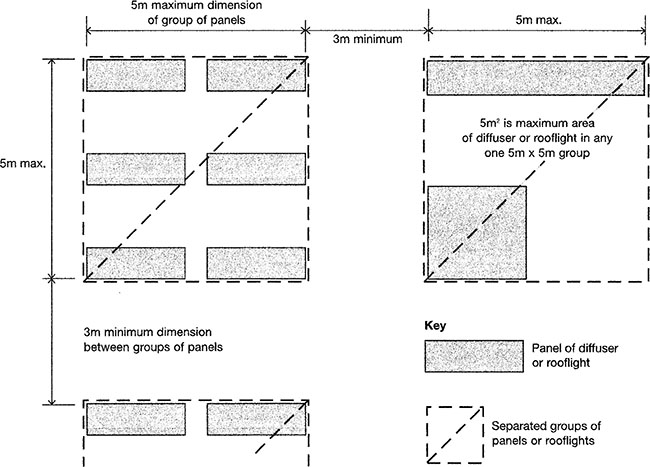
Figure 7.8.4 Layout restrictions for plastic rooflights
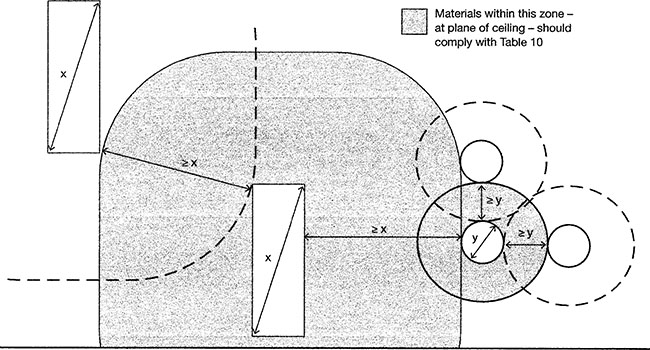
Figure 7.8.5 Layout restrictions on small rooflights
7.8.2.2.4 Compartments
p.1078
• Roofs are not treated as elements of structure unless they serve the function of a floor. |
B3.iii B2 7.4 |
• Compartment walls in a top storey beneath a roof should be continued through the roof space. |
B2 8.24 |
• A compartment wall should meet the underside of the roof covering with fire-stopping at the wall/ roof junction where necessary (see Figure 7.8.6). |
B2 8.28 |
• A zone of the roof 1500mm wide on either side of the wall should have a covering of designation AA, AB or AC on a substrate or deck of a material of limited combustibility (see Figure 7.8.6) |
B2 8.29 |
![]() Note: Thermoplastic rooflights which are regarded as having an AA (National class) designation or BROOF(t4) (European class) classification are not suitable for use in the zone described above.
Note: Thermoplastic rooflights which are regarded as having an AA (National class) designation or BROOF(t4) (European class) classification are not suitable for use in the zone described above.
• Combustible boarding used as a substrate to the roof covering, wood wool slabs, or timber tiling battens, may be carried over the compartment wall provided that they are fully bedded in mortar or other suitable material over the width of the wall in the following buildings: |
|
|
|
|
|
|
B2 8.30 |
![]() Note: Double-skinned insulated roof sheeting, with a thermoplastic core, should incorporate a band of material of limited combustibility at least 300mm wide centred over the wall.
Note: Double-skinned insulated roof sheeting, with a thermoplastic core, should incorporate a band of material of limited combustibility at least 300mm wide centred over the wall.
p.1079
• A compartment wall may be extended up through the roof for a height of at least 375mm above the top surface of the adjoining roof covering (see Figure 7.8.6) |
|
• Where there is a height difference of at least 375mm between two roofs, or where the roof coverings on either side of the wall are AA, AB or AC, this height may be reduced to 200mm. |
B2 8.31 |
• A compartment wall should carry on up through a ceiling or roof cavity to maintain the standard of fire resistance. |
B2 9.3 |
• A cavity that exists above or below any fire-resisting construction on an escape route should either be: |
|
|
|
|
B2 9.4 |
p.1080

Figure 7.8.6 Junction of compartment wall with roof
7.8.2.2.6 Double-skinned corrugated or profiled roof sheeting
• Cavity barriers need not be provided between double-skinned corrugated or profiled insulated roof sheeting if the sheeting is a material of limited combustibility and: |
|
|
|
|
B2 9.5 |
![]() Note: When a classification includes ‘s3, d2’, this means that there is no limit set for smoke production and/or flaming droplets/particles.
Note: When a classification includes ‘s3, d2’, this means that there is no limit set for smoke production and/or flaming droplets/particles.
p.1081

Figure 7.8.7 Cavity barriers in double-skinned insulated roof sheeting
p.1082
7.8.2.2.7 Institutional and other buildings
• In institutional and other residential buildings, a cavity that exists above or below partitions between bedrooms because the enclosures are not carried to full storey height, or, (in the case of the top storey) to the underside of the roof covering, should either be: |
|
|
|
|
B2 9.7 |
Table 7.8.2 Maximum dimensions of cavities in non-domestic buildings

p.1083
7.8.2.2.8 Extensive cavities
• Cavity barriers should be used to sub divide any cavity, including any roof space, so that the distance between cavity barriers does not exceed the dimensions given in Table 7.8.2. |
B2 9.8 |
• Table 7.8.2 sets out maximum dimensions for undivided concealed spaces. |
|
• Extensive concealed spaces should be subdivided to comply with the dimensions given. |
B2 9.9 |
• Table 7.8.2 does not apply to any cavity described below: |
|
|
|
|
|
|
B2 9.10 |
• Any surface finish applied to a roof of a car park, or within any adjoining building, compartment or separated part to the structure enclosing the car park need not be made of non-combustible material if the finish meets the guidance in Approved Document B2. |
11.3ei |
![]() Note: Where cavity barriers are provided in roof spaces, the roof members to which they are fitted are not expected to have any fire resistance, for the purpose of supporting the cavity barrier(s).
Note: Where cavity barriers are provided in roof spaces, the roof members to which they are fitted are not expected to have any fire resistance, for the purpose of supporting the cavity barrier(s).
p.1084
7.8.2.2.9 Fire spread
• The roof of the building shall adequately resist the spread of fire over the roof and from one building to another, having regard to the use and position of the building. |
B4(2) |
• In existing portal framed buildings there may be some form of roof venting to give early heat release. (e.g. PVC rooflights covering some 10 percent of the floor area and evenly spaced over the floor area.) |
B2 12.4c |
• A roof is not subject to the requirements on space separation unless it is pitched at an angle greater than 70° to the horizontal. |
|
• Vertical parts of a pitched roof such as dormer windows would not need to meet the provisions unless the slope of the roof exceeds 70°. |
|
• It is a matter of judgement whether a continuous run of dormer windows occupying most of a steeply pitched roof should be treated as a wall rather than a roof. |
B2 13.1 |
p.1085
7.8.2.2.10 Roof coverings
• Roof coverings near a boundary should protect against the spread of fire over the boundary. |
|
• Roof coverings may consist of one or more layers of material but does not refer to the roof structure as a whole. |
B2 14.1 |
• Fire properties of roofs should meet the requirements of Tables 6.8.3 and 6.8.4. |
B2 14.2 |
p.1086
Table 7.8.3 Specific provisions of test for fire resistance of roofs

p.1087
Table 7.8.4 Mimimum periods of fire resistance


* Increased to 30 minutes for elements protecting the means of escape.
# Reduced to 90 minutes for elements not forming part of the structural frame.
p.1088
• The size and disposition of rooflights should accord with the limits in Table 7.8.5 and with the guidance in Tables 7.8.6 and 7.8.7. |
B2 14.2 |
p.1089
• Table 7.8.6 sets out the limitations on the use of plastic rooflights which have at least a Class 3 (National class) or Class D-s3, d2 (European class) lower surface. |
B2 14.6 |
• When used in rooflights, a rigid thermoplastic sheet product made from polycarbonate or from unplasticised PVC, which achieves a Class 1 (National class) rating for surface spread of flame can be regarded as having an AA (National class) designation or BROOF(t4) (European class) classification, other than for the purposes of Figure 7.8.6. |
B2 14.7 |
Table 7.8.5 Limitations applied to thermoplastic rooflights and lighting diffusers in suspended ceilings and class 3 plastic rooflights

Table 7.8.6 Class 3 Plastic rooflights limitations on use and boundary distances


Table 7.8.7 Plastic rooflights limitations on use and boundary distances


Figure 7.8.8 Limitations on spacing and size of plastic rooflights with Class 3 or Class D-s£ or TP(b) lower surface
p.1090
• Table 7.8.7 sets out the limitations on the use of thermoplastic materials with a TP(a) rigid or TP(b) classification (see also Figure 7.8.8). |
|
• Surrounding roof covering should be a material of limited combustibility for at least 3m distance. |
|
• Rooflights should be at least 1500mm from the compartment wall. |
|
• The method of classifying thermoplastic materials is given in Appendix A to Approved Document B2. |
B2 14.6 |
• Test methods for roof coverings are specified in BS 476-3: or BS EN 13501-5. |
|
• The notional performance of some common roof coverings is given in Table 7.8.8. |
B2 14.3 |
• Rooflights are controlled on a similar basis to plastic rooflights |
B2 14.4 |
p.1091
Table 7.8.8 Notional designs for roof coverings


Notes:
* Lead sheet supported by timber joists and plain edged boarding should be regarded as having a BA designation and is deemed to be designated class CROOF(t4) (European class).
The National classifications do not automatically equate with the equivalent classifications in the European column; therefore, products cannot typically assume a European class unless they have been tested accordingly.
p.1092
• The separation distance is the minimum distance from the roof to the relevant boundary. |
|
• Table 7.8.9 sets out separation distances according to the type of roof covering and the size and use of the building. |
|
|
|
|
B2 14.5 |
• When used in rooflights, unwired glass at least 4mm thick can be regarded as having an AA designation (National class) designation or BROOF(t4) (European class) classification. |
B2 14.8 |
• Thatch and wood shingles should be regarded as having an AD/BD/CD designation or EROOF(t4) (European class) classification in Table 7.8.8 if their performance cannot be established. |
B2 14.9 |
Table 7.8.9 Limitations on roof coverings

7.8.2.2 Protection from falling, collision and impact
• Provision shall be made for any windows, skylights ceilings or roofs to be safely accessible for cleaning. |
K5.4 |
• Windows, skylights and ventilators which can be opened by people in or about the building shall be so constructed or equipped that they may be opened, closed or adjusted safely. |
K5.3 |
![]() Note: The requirement to protect building users from falling, collision and impact with windows in roofs (including skylights, rooflights and glass ceilings) is covered in greater depth in Sections 6.11 and 7.11).
Note: The requirement to protect building users from falling, collision and impact with windows in roofs (including skylights, rooflights and glass ceilings) is covered in greater depth in Sections 6.11 and 7.11).
7.8.2.3 Conservation of fuel and power
• Work in historic buildings that warrants sympathetic treatment, and where advice from others could be beneficial, includes restoring the historic character of a building that has been subject to previous inappropriate alteration, e.g. replacement rooflights. |
L2B 3.12 |
• Installation of thermal insulation in a roof space or loft space is not notifiable as long as this is the only work carried out and the work is carried out voluntarily and not in order to comply with any requirement in the Building Regulations. |
L2B 3.30c |
• A proposed extension should incorporate roof windows/rooflights that meet the standards. |
L2B 4.3a |
• The area of windows and rooflights in an extension should generally not exceed the following values: |
|
|
|
|
|
|
p.1093
p.1094
|
|
|
L2B 4.4 |
• If an existing roof window or rooflight which separates a conditioned space from an unconditioned space or the external environment has a U-value that is worse than 3.3W/m2K, the guidance in paragraphs 4.23 to 4.28 of Approved Document L2B (below) should be followed. |
L2B 4.19d |
• The application of the term controlled fitting to a roof window or rooflight refers to a whole unit, i.e. including the frame. |
|
• Replacing the glazing while retaining an existing frame is not providing a controlled fitting, and so such work is not notifiable. |
L2B 4.23 |
p.1095
• Where roof windows or rooflights are to be provided, reasonable provision in normal cases would be the installation of draughtproofed units whose performance is no worse than: |
|
|
|
|
|
• If a rooflight is enlarged or a new one created, the area of the windows and pedestrian doors and of rooflights expressed as a percentage of the total floor area of the building should not exceed 20 percent or should be compensated for in some other way. |
L2B 4.24 |
• U-values of windows, roof windows, rooflights and doors are calculated using the methods and conventions set out in BRE Report BR 4436, and should be based on the whole unit. |
L2B 4.25 |
• The U-values for roof windows and rooflights given in Table 7.8.10 are based on the U-value having been assessed in the vertical position. |
|
• If a particular unit has been assessed in a plane other than the vertical, the standards given in the Approved Document should be adjusted following the guidance given in BR 443. |
L2A 2.41 L2B 4.26 |
Table 7.8.10 Limiting fabric parameters – roofs existing buildings

• In certain classes of building with high internal gains, a less demanding U-value for glazing may be an appropriate way of reducing overall CO2 emissions. |
|
• If this case can be made the average U-value for rooflights can be relaxed from the values given above (4.24) but the value should not exceed 2.7W/m2K. |
L2B 4.27 |
• Replacing existing roof windows or rooflights which have a U-value worse than 3.3W/m2K following the guidance in paragraphs 4.23 to 4.28 (above) is considered to be practical and economically feasible in ordinary circumstances. |
L2B Table 6 |
• Where the installed capacity per unit area of a heating system is increased existing roof windows or rooflights within the area served and which have U-values worse than 3.3W/m2K should be replaced following the guidance in paragraphs 4.23 to 4.28 (above). |
L2B 6.10 |
• Where the installed capacity per unit area of a cooling system is increased and the area of windows and roof windows within the area served exceeds 40 percent of the façade area, or the area of rooflights exceeds 20 percent of the area of the roof and the design solar load exceeds 25W/m2K, then the solar control provisions should be upgraded. |
L2B 6.11 |
• In existing buildings the Target CO2 Emission Rate (TER) is based on a building of the same size and shape as the actual building, constructed to a concurrent specification. |
p.1096
• If the actual building is constructed entirely to this specification it will meet the TER and therefore pass Criterion 1. |
|
• Table 7.8.11 provides a summary of the concurrent notional building specifications for each category of building. |
|
• More detailed information can be found in the National Calculation Methodology (NCM) modelling guide. |
L2A 5.1 |
Table 7.8.11 Concurrent notional building specification

7.9.1 Requirements
This section provides the details for buildings other than dwellings only where they differ from the requirements already given in Chapter 6.9.

![]() Note: Approved Documents B2 (Fire safety), and L2B (Conservation of fuel and power) apply specifically to buildings other than dwellings.
Note: Approved Documents B2 (Fire safety), and L2B (Conservation of fuel and power) apply specifically to buildings other than dwellings.
7.9.2 Meeting the requirement
7.9.2.1 Fire safety
p.1097
• Openings in compartment walls or compartment floors may be made for chimneys, appliance ventilation ducts or ducts encasing one or more flue pipes that meet the provisions in Section 9 of Approved Document B2. |
B2 8.34 |
7.9.2.2 Conservation of fuel and power
• If a ventilation appliance is installed in a room containing a natural-draught open-flued combustion appliance or service, such as a gas fire which uses a chimney as its flue, the work will remain notifiable building work. |
L2B 3.30biii |
p.1098
7.10.1 Requirements
This section provides the details for buildings other than dwellings only where they differ from the requirements already given in Chapter 6.10.


![]() Note: Approved Documents B2 (Fire safety) and M2 (Access to and use of buildings) apply specifically to buildings other than dwellings. There are separate requirements relating to protection from falling, collision and impact in Approved Document K1which relate specifically to buildings other than dwellings.
Note: Approved Documents B2 (Fire safety) and M2 (Access to and use of buildings) apply specifically to buildings other than dwellings. There are separate requirements relating to protection from falling, collision and impact in Approved Document K1which relate specifically to buildings other than dwellings.
![]() The Workplace (Health, Safety and Welfare) Regulations 1992 contain some requirements which affect building design. These Regulations also apply to the common parts of flats and similar buildings if people such as cleaners, wardens and caretakers are employed to work in these common parts.
The Workplace (Health, Safety and Welfare) Regulations 1992 contain some requirements which affect building design. These Regulations also apply to the common parts of flats and similar buildings if people such as cleaners, wardens and caretakers are employed to work in these common parts.
7.10.2 Meeting the requirement
7.10.2.1 Fire safety
When designing a means of escape, there should be an alternative way for people to flee from most situations. The fire safety requirements relating to stairs in buildings other than dwellings are quite comprehensive and they differ from those for dwellings.
If you are at all unsure which regulation to apply, you should seek advice from your Local Authority or local fire service, which have responsibility for enforcing the Regulatory Reform (Fire Safety) Order 2005.
p.1099
7.10.2.1.1 General
![]() People in wheelchairs may not be able to use stairways without assistance. It may therefore be necessary to provide refuges on escape routes, assistance down (or up) stairways or suitable lifts.
People in wheelchairs may not be able to use stairways without assistance. It may therefore be necessary to provide refuges on escape routes, assistance down (or up) stairways or suitable lifts.
p.1100
• The combustible content of such stairways should be restricted. |
B2 B1.iii B2 2.40 |
• Where direct escape is impossible, it should be possible to reach a place of relative safety, such as a protected stairway, which is on a route to an exit, within a reasonable distance. |
B2 B1.v |
• Protected stairways provide virtually ‘fire sterile’ areas and should lead to places of safety outside the building. |
|
• People inside a protected stairway may be considered to be safe from immediate danger from flame and smoke. |
|
• Flames, smoke and gases must be excluded by using fire-resisting structures or by an appropriate smoke-control system, or by a combination of both these methods. |
B2 B1.ix |
• A stairway or shaft that passes directly from one compartment to another should be enclosed in a protected shaft. |
B2 8.35 |
|
|
|
B2 8.36 B2 8.7 |
• If a basement storey contains a habitable room, either an external exit door or window or a protected stairway leading from the basement to a final exit should be provided. |
B2 2.6 |
7.10.2.1.2 Student accommodation
• A kitchen in student accommodation that is not separated from the stairway by a door should have an interlinked heat detector or heat alarm as well as smoke alarms. |
B2 1.12 |
• Smoke alarms should not be fixed over stairs in student accommodation. |
B2 1.15 |
7.10.2.1.3 Galleries
• The foot of the access stair in a gallery should be no more than 3m from the door to the room containing the gallery. |
B2 2.8b |
• The head of an access stair should be less than 7.5m from any point on a gallery. |
B2 2.8c |
• Any cooking facilities in a room containing a gallery should be remote from the stair to the gallery and positioned such that they do not prejudice the escape from the gallery. |
B2 2.8dii |
p.1101
7.10.2.1.4 Flats
• There should be direct access from all habitable rooms in a multistorey flat to an internal protected stairway leading to a final exit. |
B2 2.12 |
• A multistorey flat (above 4.5m) without its own external entrance at ground level should have a protected stairway. |
B2 2.16 |
• An alternative exit from a flat should lead to a final exit or common stair. |
B2 2.17 |
• Where an air circulation system circulates air within an individual flat and an internal protected stairway, the following precautions should be taken: |
|
|
|
|
|
|
|
|
|
|
B2 2.18 B2 5.47 |
Note: There are separate arrangements for small single-storey non-residential buildings and annexes (Section 7.8.1).
p.1102
p.1103
• Every flat should have access to alternative escape routes. |
|
• A single escape route from a flat entrance door is acceptable if: |
|
|
|
|
B2 2.20 |
• Escape routes in common areas should comply with the following: |
|
|
|
|
|
• People should not have to pass through one stairway enclosure to reach another. |
|
• It is acceptable to pass through a protected lobby of one stairway in order to reach another. |
B2 2.23 |

Figure 7.10.1 Flats served by one common stair
7.10.2.1.5 Small single-stair buildings
• In small single-stair buildings, the escape shown in Figure 7.10.3 may be used provided that: |
|
|
|
|
|
|
B2 2.21 B2 5.43 |
|
|
|

Figure 7.10.2 Flats served by more than one common stair
The distance of travel is measured to the foot of the stair in a basement or to the head of the stair in a first storey. Two or more exits or stairs should afford effective alternative directions of travel from any point.
p.1104
7.10.2.1.6 Ventilation
• There should be some means of ventilating common corridors/lobbies and stairs. |
B2 2.25 |
• In buildings, other than small ones, the corridor adjoining the stair should have a vent. |
|
• The vent from the corridor/lobby should be as high up as practicable with the top edge at least as high as the top of the door to the stair. |
B2 2.26 |
• There should be a vent, with a free area of at least 1.0m2 from the top storey of the stairway to the outside. |
|
• In single-stair buildings smoke vents on the fire floor and at the head of the stair should be actuated by smoke detectors in the access space to the flats. |
|
• In buildings with more than one stair, smoke vents may be actuated manually and the control system should ensure that the vent at the head of the stair opens either before, or at the same time, as the vent on the fire floor. |
|
• On detection of smoke in the common corridor/lobby, the vent(s) on the fire floor, the vent at the top of the smoke shaft and to the stairway should all open simultaneously. |
• Mechanical ventilation may be provided to protect the stair(s) from smoke. |
|
• Guidance on the design of smoke-control systems is available in BS EN 12101-6. |
B2 2.27 |
• Door(s) should be positioned so that smoke will not affect access to more than one stairway. |
B2 2.28 |
• A separate ventilation system should be provided for each protected stairway. |
B2 5.47 |

Figure 7.10.3 Common escape route in a small single-stair building. OV = Openable vent at high level for fire service use. D = Dwelling. fd F= ire door
p.1105
7.10.2.1.7 Common stairs
• A single common stair may be acceptable in some cases. |
|
• Access to more than one common stair is preferred. |
B2 2.32 |
• A stair of acceptable width for everyday use is sufficient for escape purpose. |
B2 2.33 |
p.1106
• Common stairs should have a satisfactory standard of fire protection. |
B2 2.34 |
• A stair may also serve as a firefighting stair. |
|
• A firefighting stair should be at least 1100mm wide. |
B2 2.33 B2 2.35 |
• Every common stair should be within a fire-resisting enclosure. |
B2 2.36 |
• The appropriate level of fire resistance for common stairs is given in Table 7.10.1. |
B2 2.37 |
• If a common stair forms part of the only escape route from a flat, it should not also serve any covered car park, boiler room, fuel storage space or other ancillary accommodation of similar fire risk (except in small buildings). |
B2 2.46 |
• A common stair which does not form part of the only escape route from a flat may also serve ancillary accommodation if it is separated from the ancillary accommodation by a protected lobby or a protected corridor. |
|
• If the stair serves an enclosed (non-open-sided) car park, or place of special fire hazard, the lobby or corridor should have not less than 0.4m2 permanent ventilation or be protected from the ingress of smoke by a mechanical smoke-control system. |
B2 2.47 |
Table 7.10.1 Specific provisions of test for fire resistance of elements of structure – stairs

7.10.2.1.8 Protected stairs
• Every protected stairway should discharge: |
|
|
|
|
B2 2.38 B2 4.36 |
Note: Protected exit passageways should have the same standard of fire resistance and lobby protection as the stairway it serves.
• Two adjacent protected stairways should be separated by an imperforate enclosure. |
B2 2.39 B2 4.37 |
• A protected stairway should be relatively free of potential sources of fire. |
|
• A protected stairway may be used as a lift well or for an electricity meter. |
|
• In single-stair buildings, meters located within the stairway should be enclosed within a secure cupboard which is separated from the escape route with fire-resisting construction. |
B2 2.40 B2 4.38 |
• If a protected stairway projects beyond, or is recessed from, or is in an internal angle of, the adjoining external wall of the building which has little fire resistance, then the distance between an unprotected area in the external enclosures and unprotected area in the enclosure to the stairway should be at least 1800mm (Figure 7.10.4). |
B2 2.41 B2 5.24 |
p.1107
• Gas service and installation pipes or associated meters may only be installed in a protected stairway if they comply with the Pipelines Safety Regulations 1996, SI 1996 No 825 and the Gas Safety (Installation and Use) Regulations 1998 SI 1998 No 2451. |
B2 2.42 B2 4.39 |
• Doors to a protected stairway should be fitted with an automatic release mechanism, otherwise the stairway should not form part of the primary circulation route. |
B2 3.14 |
• Where more than one escape route is available from a storey part of the escape may be via an external escape stair provided that: |
|
|
B2 2.48 B2 2.49 |
|
|
|
|
|
|
• If the building has a single access stair, that stair may be external if it serves a floor less than 6m above ground level. |
|
• All access doors to the stair should be fire-resisting and self-closing. |
|
• Any part of the external envelope of the building within 1800mm of (and 9m vertically below) the flights and landings of an external escape stair should be of fire-resisting construction. |
|
• Any part of the building (including any doors) within 1800mm of the escape route from the stair to a place of safety should be protection by fire-resisting construction unless there is a choice of routes from the foot of the stair. |
|
• Any external stair more than 6m tall should be protected from the effects of adverse weather. |
B2 4.44 B2 4.45 B2 5.25 |
• In buildings with not more than three storeys above the ground storey, stairs may serve both flats and other occupancies, provided that the stairs are separated from each occupancy by protected lobbies at all levels. |
B2 2.50 |
• In buildings with more than three storeys above the ground storey, stairs may serve both flats and other occupancies provided that: |
|
|
|
|
|
|
|
|
B2 2.51 |
• Rooflights in protected stairways may not be constructed of a thermoplastic material. |
B2 6.12 |
• In buildings without sprinklers then every part of every storey that is more than 18m above fire and rescue service vehicle access level should be no more than 45m from a fire main outlet contained in a protected stairway. |
|
• Additional fire mains may be required in escape stairs. |
B2 17.10 |
p.1108
![]() Note:
Note:
1. Additional measures, including increased periods of fire resistance may be required between the flat and any storage area where fuels such as petrol and LPG are present.
2. The stair enclosure should have at least the standard of fire resistance as stipulated in Table 7.10.2.
p.1109

Figure 7.10.4 External protection to protected stairways
p.1110
7.10.2.1.9 Basements
p.1111
• Special measures are needed to prevent a basement fire endangering upper storeys. |
B2 2.43 B2 4.41 |
• An escape stair that is the only escape route from an upper storey of a building should not be continued down to serve any basement storey unless it is a small building. |
|
• The basement should be served by a separate stair. |
B2 2.44 B2 4.42 |
• If an upper storey of a building has more than one escape stair, only one of the stairs need be terminated at ground level. |
B2 2.45 B2 4.43 |
• Other stairs may connect with the basement storey(s) if there is a protected lobby or a protected corridor between the stair(s) and accommodation at each basement level. |
|
• In basements and enclosed (non-open-sided) car parks, the lift should be approached by a protected lobby or corridor, unless it is within the enclosure of a protected stairway. |
B2 5.43 |
• Vents should be provided in stairways from basements. |
B2 B5.iie |
p.1112
Table 7.10.2 Minimum periods of fire resistance


* Increased to 30 minutes for elements protecting the means of escape.
# Reduced to 90 minutes for elements not forming part of the structural frame.
7.10.2.1.10 Live/work units
• Where a flat serves as a workplace for its occupants and for persons who do not live on the premises, the following additional fire precautions will be necessary: |
|
|
|
|
B2 2.528 |
![]() Note: Where the unit is so large that the travel distance cannot be met then the design of the building should be considered on a case-by-case basis.
Note: Where the unit is so large that the travel distance cannot be met then the design of the building should be considered on a case-by-case basis.
7.10.2.1.11 Multistorey buildings
• In multistorey buildings, more than one stair may be needed for escape. |
|
• Every part of each storey will need to have access to more than one stair. |
|
• Where there is a dead end, an alternative stair should be accessible. |
B2 3.3 |
• The escape from any storey which has more than one escape stair should not pass through one stairway to reach another. |
|
• It is acceptable to pass through a protected lobby to reach another stair. |
B2 3.13 |
• If a storey or room has two- or more storey exits, it should be assumed that a fire might prevent the occupants from using one of them. |
|
• The remaining exit(s) need to be wide enough to allow all the occupants to leave quickly. |
B2 3.21 |
• If a ground floor storey shares a final exit with a stair via a ground floor lobby, the width of the final exit should be sufficient to enable a maximum evacuation flow rate equal to or greater than that from the storey exit and stair combined using the following formula: |
|
W = ((N/2.5) + (60S))/80 |
|
where: |
|
W = width of final exit in metres |
|
N = number of people served by ground floor storey exit |
|
S = stair width in metres |
B2 3.23 |
• In a multistorey buildings there should be a sufficient number of adequately sized and protected escape stairs. |
B2 4.1 |
• The number of escape stairs needed in a building will be determined by: |
|
|
|
|
|
|
|
B2 4.2. |
• In larger buildings, provisions the fire and rescue service may be required. |
|
|
|
|
B2 4.3 |
p.1113
7.10.2.1.12 Single escape stairs
Table 7.10.3 shows the limitations on travel distance which must be applied to buildings with single escape stairs.
• A building may be served by a single escape stair if: |
|
|
|
|
B2 4.5 |
• A single escape stair may be used from: |
|
|
|
|
|
|
|
|
|
|
|
|
|
|
|
|
|
|
B2 4.6 |
Table 7.10.3 Limitations on travel distance

p.1114
7.10.2.1.13 Refuges
• Refuges are relatively safe waiting areas for short periods. |
|
• Disabled people should not be left alone indefinitely in a refuge. |
|
• A refuge should be provided for each protected stairway affording egress from each storey, except storeys consisting exclusively of plant rooms. |
B2 4.7 |
• A refuge should be provided for each stairway, but need not be located within the stair enclosure as long as it enables direct access to the stair. |
|
• The following are examples of satisfactory refuges: |
|
|
|
|
B2 4.8 |
• Where a refuge is a protected stairway: |
|
|
|
|
B2 4.9 |
• Where a refuge is in stairway, the sign should be accompanied by an additional blue mandatory sign worded ‘Refuge – keep clear’. |
B2 4.10 |

Figure 7.10.5 Refuge formed by compartmentation
p.1115
7.10.2.1.14 Escape stairs
Suitable escape stairs should be provided. The minimum widths of escape stairs are shown in Table 7.10.4.

Figure 7.10.6 Refuge formed in a protected stairway
Table 7.10.4 Minimum widths of escape stairs

p.1116
• The width of escape stairs should: |
|
|
|
|
|
|
|
• Tall buildings may require additional stairs so that people can stay within reach of a handrail on a prolonged descent. |
B2 4.15 |
• Where a stair wider than 1400mm is provided with a central handrail, then the stair width on each side of the central handrail should be considered separately. |
|
• Stairs in public buildings which are more than 1800mm should have a central handrail. |
B2 4.16 |
• A stair may require an increased width if it also serves the ground and/or basement storey. |
B2 4.17 |
• Every escape stair should be wide enough to accommodate the number of persons needing to use it in an emergency this is dependent on: |
p.1117
p.1118
|
|
|
B2 4.18 |
• Where the maximum number of people needing to use the escape stairs is unknown, the occupant capacity should be calculated on the basis of the appropriate floor space factors. |
B2 4.19 |
• Where two or more stairs are provided it should be assumed that one of them may not be available due to fire. |
|
• To ensure that the capacity of the remaining stair(s) is adequate, each stair should be discounted in turn. |
|
• The stair discounting rule applies to a building fitted with a sprinkler system. |
B2 4.20 |
• The discounting rules do not apply if the escape stairs are: |
|
|
|
|
B2 4.21 |
• The escape stairs in a building designed for simultaneous evacuation should have sufficient capacity to allow all floors to be evacuated simultaneously. |
p.1119
p.1120
p.1121
• Account should be taken of the number of people temporarily housed in the stairways during the evacuation when calculating the width of the stairs. |
B2 4.22 |
• Escape based on simultaneous evacuation should be used for: |
|
|
|
|
|
|
B2 4.23 |
p.1122
![]() Note: BS 5588-7 includes designs based on simultaneous evacuation.
Note: BS 5588-7 includes designs based on simultaneous evacuation.
• The capacity of stairs for simultaneous evacuation is used is given in Table 7.10.5. |
|
• The capacity of stairs serving more than ten storeys should be obtained by using linear extrapolation. |
B2 4.24 |
• As an alternative to using Table 7.10.5 the capacity of stairs 1100mm or wider can be derived from the formula: |
B2 4.25 |

p.1123
Table 7.10.5 Capacity of a stair for basements and simultaneous evacuation of the building

p.1124
or |
|
w = P + 15n − 15 |
p.1125
where: |
|
P = the number of people that can be served |
|
w = the width of the stair, in metres |
|
n =the number of storeys served |
|
Note: Separate calculations should be made for stairs/flights serving basement storeys and those serving upper storeys. |
|
• Escape stairs should have a satisfactory standard of fire protection. |
B2 4.31 |
• Every internal escape stair should be a protected stairway. |
|
• An unprotected stair may be part of an internal route to a storey exit or final exit, provided that the distance of travel and the number of people involved are very limited. |
p.1126
• If the protected stairway is also a protected/firefighting shaft additional measures may be required. |
B2 4.32 |
• A stair in small premises, which is not a bar or restaurant, may be open as long as: |
|
|
p.1127
|
|
|
|
|
|
|
B2 4.33 |
• Fixed ladders should not be used as a means of escape for members of the public but may be used in plant rooms. |
B2 5.22b |
7.10.2.1.15 Phased evacuation
• Stairs in high buildings should be designed on the basis of phased evacuation. |
|
• In phased evacuation, the first people to be evacuated are all those of reduced mobility and those on the storey most immediately affected by the fire. |
|
• Subsequently, evacuation takes place two floors at a time. |
|
• This method is not suitable for every type of building and depends on the provision (and maintenance) of certain supporting facilities such as fire alarms. |
|
• Phased evacuation enables narrower stairs to be incorporated than would be the case if simultaneous evacuation were used. |
|
• Phased evacuation reduces disruption in large buildings. |
B2 4.26 |
• Where a building is designed on the basis of phased evacuation the stairways should be approached through a protected lobby or protected corridor at each storey (except the top). |
B2 4.29 |
• The minimum width of stairs for phased evacuation is given in Table 7.10.6. This table assumes a phased evacuation of the fire floor first, followed by evacuation of not more than two floors at a time. |
B2 4.30 |
Table 7.10.6 Minimum widths of stairs designed for phased evacuation

7.10.2.1.16 Access lobbies and corridors
• An escape stair should have the added protection of a protected lobby/corridor when: |
|
|
|
|
|
|
|
|
B2 4.34 |
• A protected lobby should be provided between an escape stairway and a place of special fire hazard. |
|
• The lobby should have not less than 0.4m2 permanent ventilation, or be protected by a mechanical smoke-control system. |
B2 4.35 |
p.1128
7.10.2.1.17 External escape stairs
• Flights and landings on escape stairs should be made of materials of limited combustibility |
B2 5.319 |
• Single steps should only be used on escape routes where they are prominently marked. |
|
• A single step on the line of a doorway is acceptable. |
|
• Where a final exit is accessed without the need to first traverse steps then a level threshold and, where necessary, a ramp should be provided. |
B2 5.21 B2 5.32 |
• Escape stair lighting should be on a separate circuit from the supply for any other part of the escape route. |
B2 5.33 |
• An external escape stair should meet the following: |
|
|
|
|
|
|
|
|
|
B2 5.25 |
• Refuse chutes and rooms provided for the storage of refuse should be separated from other parts of the building by fire-resisting construction. |
p.1129
• Refuse chutes and rooms provided for refuse storage should not be within protected stairways. |
B2 5.55 |
• An uninsulated glazed screen may be used in the enclosure to a protected shaft between a stair and a lobby or corridor which is entered from the stair if: |
|
|
|
|
|
|
B2 8.38 |
p.1130

Figure 7.10.7 Fire resistance adjacent to external stairs
p.1131
• Protected shaft containing a stair should not also contain a pipe conveying oil. |
B2 8.40 |
• Any part of an external wall of a stairway in a protected shaft is excluded from the assessment of unprotected area. |
B2 13.8 |
• The outlets from fire mains should be located within the protected enclosure of a stairway or a protected lobby where one is provided. |
B2 15.5 |
• A firefighting stair and any firefighting lift should serve all intermediate storeys between the highest and lowest storeys. |
B2 17.5 |
• Every firefighting stair should be approached from the accommodation, through a firefighting lobby (except in blocks of flats). |
B2 17.11 |
p.1132
Table 7.10.7 Limitations on the used on uninsulated glazed elements on escape routes


7.10.2.1.18 Helical and spiral stairs
p.1133
• Helical stairs, spiral stairs and fixed ladders may form part of an escape route subject to the following restrictions: |
|
|
|
|
|
|
|
|
B2 5.22 |
• Guidance on the design of helical and spiral stairs and fixed ladders, from the aspect of safety in use, is given in Section 7.10.2.3. |
B2 5.23 |
p.1134
7.10.2.1.19 Lifts
p.1135

7.10.2.2 Protection from falling, collision and impact
7.10.2.2.1 Construction of steps
The requirements for the construction of steps in buildings other than dwellings is more stringent than the requirements for dwellings.
p.1136
• Risers should not be open. |
K 1.6 |
• The rise and going should be measured in accordance with Figure 7.10.8. |
K 1.2 |
• For buildings other than dwellings and for common access areas in buildings that contain flats all means of escape routes should have a minimum clear headroom of 2m, except in doorways. |
K 1.12 |
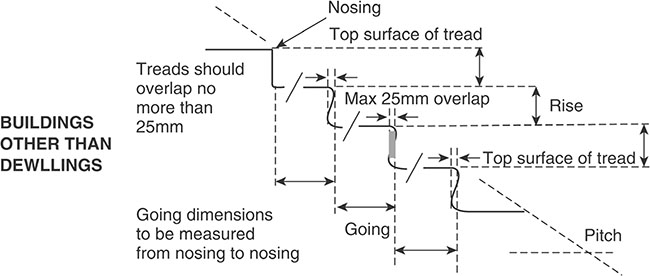
Figure 7.10.8 Measuring the rise and going in buildings other than dwellings
p.1137
• Step nosings should be made apparent. |
|
• Step nosings should be a minimum of 55mm wide on both the tread and the riser. |
|
• Step nosings should not protrude over the tread below (if it does protrude it should be by no more than 25mm). |
K 1.7 |
• If the soffit beneath a stair is less than 2m above floor level then the area beneath the stair should be protected with either guarding and low-level cane detection or a barrier. |
K 1.8 |
• In flights of stairs all of the following should be provided: |
|
|
|
|
|
|
K 1.15 |
• Single steps should be avoided. |
|
• The maximum number of risers on flights between landings should be: |
|
|
p.1138
|
K 1.18 |
• An unobstructed length of 1200mm should be provided on each landing. |
|
• Doors should not swing across landings. |
K 1.23 |
• Suitable continuous handrails should be provided (dimensions are shown in Figure 7.10.9) on each side of the flights and on each side of the landings. |
K 1.35 |
• Handrails should be provided in accordance with all of the following: |
|
|
|
|
|
|
|
|
|
|
|
|
K 1.36 |
• Guarding should be provided at the sides of flights and landings with two or more risers. |
K 1.40 |
• Where stairs or ladders are used to access maintenance areas: |

Figure 7.10.9 Key dimensions for fandrails to stairs in buildings other than dwellings
|
|
|
K 1.42 |
7.10.2.2.2 Ramps
p.1139
• Ramp should be readily apparent or clearly signposted. |
K 2.2 |
• A ramp surface should be selected in accordance with both of the following: |
|
|
|
|
K 2.4 |
• A kerb on the open side of any ramp or landing, in addition to any guarding should be minimum of 100mm high and contrast visually with the ramp or landing. |
K 2.5 |
• Where the change of level is 300mm or more in addition to the ramp there should be two or more clearly signposted steps. |
K 2.6 |
• If the change of level is less than 300mm a ramp should be provided instead of a single step. |
p.1140
• If the soffit beneath any ramp is less than 2m above floor level, the area beneath should be protected with guarding and low-level cane detection or a barrier giving the same degree of protection. |
K 2.7 |
• A ramp that provides access for people should have a minimum width between walls, upstands or kerbs of 1500mm. |
K 2.9 |
• Ramps should be kept clear of permanent obstructions. |
K 2.10 |
• A handrail should be provided on both sides of the ramp and design them to comply with paragraph K 1.36 (above). |
K 2.11 |
• All of the following should be provided: |
|
|
|
|
|
|
|
|
|
|
|
|
|
|
|
|
|
|
|
|
K 2.12 K 2.13 |
7.10.2.3 Access to and use of buildings - Buildings other than dwellings
In order to assist people in to gain access to and use the building and its facilities, a range of accessible stairs or ramps may be required. Alternatively, lifting devices may be required adjacent to stairs and ramps.
• Some people will find a stair is easier to use than a ramp. |
M2 1.3 |
• Ramps are not necessarily safe and convenient for ambulant disabled people. |
|
• Because of the increased risk of slipping on a ramp in bad weather, steps should be provided as well as a ramp. |
M2 1.21 |
• Handrails should be set at heights that are convenient for all users of the building. |
|
• Handrails should extend safely beyond the top and bottom of a flight of steps, or a ramp. |
|
• A second handrail may be required on stairs in a wide range of building types, particularly in schools, for use by children and people of short stature. |
M2 1.36 |
• Handrails should protrude no more than 100mm into a ramped or stepped access. |
M2 1.37 |
p.1141
7.10.2.3.1 Lifting devices and stair lifts
p.1142
• Internal stairs should always be provided as well as a lifting device. |
M2 3.19 |
• A wheelchair platform stairlift may be considered in an existing building provided its installation does not conflict with requirements for means of escape. |
M2 3.23 |
• The illumination in a passenger lift car, lifting platform or wheelchair platform stairlift should minimize glare, reflection, shadows or pools of light and dark. |
M2 3.26 |
• Wheelchair platform stairlifts should: |
|
|
|
|
|
|
|
|
|
|
M2 3.44 M2 3.24d M2 3.49 |
p.1143
|
|
|
|
|
|
|
|
|
|
|
|
|
|
• Wheelchair platform stairlifts: |
|
|
M2 3.45 |
|
M2 3.46 |
|
M2 3.47 |
|
M2 3.48 |
p.1144
7.10.2.3.2 Internal stairs
• A hazard warning surface is not required at the head of internal stairs. |
|
• Stairs should not be directly in line with an access route. |
|
• A going of at least 300mm is preferred for mobility-impaired people. |
M2 3.50 |
p.1145
7.11.1 Requirements
This section provides the details for buildings other than dwellings only where they differ from the requirements already given in Chapter 6.11.

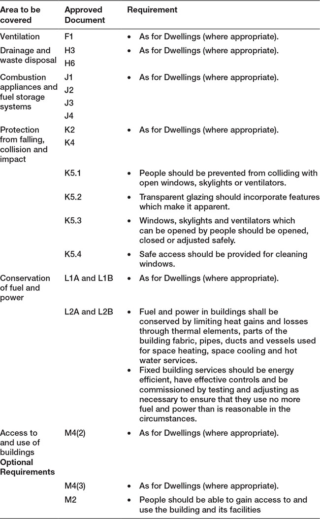
Note:
1. Approved Documents B2 (Fire safety), L2A and L2B (Conservation of fuel and power) and M2 (Access to and use of buildings) apply specifically to buildings other than dwellings.
p.1146
2. Approved Document K 5.1, 5.2, 5.3 and 5.4 apply to buildings other than dwellings.
3. Approved Document Q (Security) only applies to dwellings.
7.11.2 Meeting the requirement
7.11.2.1 Structure
7.11.2.1.1 Small single-storey non-residential buildings and annexes
p.1147
• Window openings are permitted in small single-storey buildings. |
|
• There should be no other openings within 2m of a wall containing a major opening. |
|
• If a wall does to contain a major opening the aggregate size of openings in the wall should not exceed 2.4m2. |
|
• There should not be more than one opening between piers. |
|
• The distance from a window to a corner should be more than 390mm (unless there is a corner pier). |
|
• The size and location of these openings should be in accordance with Figure 7.12.1. |
A 2C38ii |
7.11.2.1 Fire safety
7.11.2.1.1 General
Note: Cavity barriers around openings may be formed by the window or door frame if the frame is constructed of steel or timber.
p.1148
• Locks and child resistant safety stays may be provided on escape windows. |
B2 i,i |
• With increasing height, more complex provisions are needed because emergency egress through upper windows becomes increasingly hazardous. |
B2 2.1 |
• A gallery should be provided with an alternative exit. |
B2 2.8 |
• Where the gallery floor is not more than 4.5m above ground level it may be provided with an emergency egress window. |
|
• Any window provided for emergency egress from a gallery should comply with the following conditions: |
|
|
|
|
|
|
|
|
|
|
|
|
|
|
B2 2.9 |
• All habitable rooms (except for kitchens) should have an external door or window suitable for egress unless the room opens directly onto a hall leading to the entrance or an exit. |
|
• A single window can be accepted as an escape route for two rooms provided both rooms have their own access to the stairs. |
|
• A communicating door between the rooms should be provided so that it is possible to access the window without passing through the stair enclosure. |
B2 2.6 B2 2.11 B2 2.12 |
• Windowless accommodation in the following building types should have escape lighting which illuminates the route if the main supply fails: |
|
|
|
|
|
|
B2 2.52b |
|
|
|
|
|
|
|
|
• Standards for the installation of a system of escape lighting are given in BS 5266-1. |
|
• Access to refuse storage chambers should not be near flat windows. |
B2 5.57 |
• A window frame or frames in which glazing is fitted cannot be categorised as a wall. |
B2 6.2 d |
• The frame of a window or rooflights cannot be categorised as a ceiling. |
B2 6.3 |
• Thermoplastic materials may be used in windows and rooflights in suspended ceilings. |
B2 6.10 |
• External windows to rooms may be glazed with thermoplastic materials, if the material can be classified as a TP(a) rigid product. |
|
• Internal glazing should meet the provisions in Table 7.11.1. |
B2 6.12 |
p.1149
Note: Windows are not acceptable as final exits.
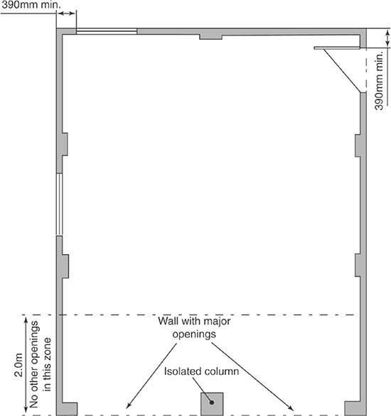
Figure 7.11.1 Size and location of openings
Table 7.11.1 Classification of linings

• Rooflights to rooms and circulation spaces may be made of a thermoplastic material if: |
|
|
|
|
B2 6.12 |
Table 7.11.2 Limitations applied to thermoplastic rooflights and lighting diffusers in suspended ceilings and Class 3 Plastic rooflights

Table 7.11.3 Class 3 Plastic rooflights limitations on use and boundary distances

Table 7.11.4 TP(a) and (b) plastic rooflights limitations on use and boundary distances


• Dormer windows (which taken in isolation might be regarded as a wall), would not need to meet the provisions of space separation unless the slope of the roof exceeds 70°. |
|
• It is a matter of judgement whether a continuous run of dormer windows occupying most of a steeply pitched roof should be treated as a wall rather than a roof. |
B2 13.1 |
• Compartments containing the rooms in basements which have external windows do not need smoke outlets. |
B2 18.6 |
• Concessions are made for thermoplastic materials used for window glazing and rooflights within suspended ceilings. |
B2 App A.19 |
p.1150
7.11.2.2 Protection from falling, collision and impact
![]() Note: For work relating to projecting windows, skylights and ventilators you should also consider Regulation 15(2) of the Workplace (Health, Safety and Welfare) Regulations 1992.
Note: For work relating to projecting windows, skylights and ventilators you should also consider Regulation 15(2) of the Workplace (Health, Safety and Welfare) Regulations 1992.
7.11.2.2.1 Prevention of collision with open windows
• People should be prevented from colliding with open windows, skylights or ventilators. |
K 5.1 |
• Where parts of windows, skylights and ventilators project inside or outside a building, this should be indicated and guarded as shown in Figures 7.11.2 and 7.11.3. |
|
• In spaces which are used infrequently and only for maintenance the projecting part should be clearly marked rather than guarding. |

Figure 7.11.2 Marking by a barrier

Figure 7.11.3 Marking by a surface
7.11.2.2.2 Critical locations
• Critical locations include large uninterrupted areas of transparent glazing which form, or are part of, the internal or external walls and doors of shops, showrooms, offices, factories, public or other non-domestic buildings. |
K 7.1 |
• The risk of collision is greatest when two parts of the building, or the building and its immediate surroundings, are at the same level but separated by transparent glazing and people may think they can walk from one part to the other. |
K 7.2 |
• There are two methods to indicate glazing, permanent and alternative methods. |
K 7.3 |
• Permanent manifestation to make glazing apparent include all of the following: |
|
|
|
|
|
|
|
|
|
|
K 7.4 |
• Alternative indications of glazing include items such as mullions, transoms, door framing or large pull or push handles (see Figure 7.11.5). |
K 7.4 |
p.1151
7.11.2.2.3 Location of controls
• The controls to operate windows and skylights should have one of the following: |
|
|
|
|
K 8.1 |

Figure 7.11.4 Height of manifestation for glass doors and glazed screens

Figure 7.11.5 Examples of door-height glazing not warranting manifestation

Figure 7.11.6 Height of controls
7.11.2.2.4 Safe access methods
• If it is not possible to safely clean a glazed surface standing on the ground, a floor or other permanent stable surface then one of the following methods should be used: |
|
|
|
|
|
|
|
|
|
|
|
|
K 9.1 |

Figure 7.11.7 Safe reaches for cleaning
p.1152
7.11.2.2.5 Ladder access
• Access should be provided as follows: |
|
|
|
|
|
|
|
|
|
|
|
|
|
|
|
|
|
|
|
|
7.11.2.2.6 Robustness
Some glazing materials (such as annealed glass) gain strength through thickness; others such as polycarbonates or glass blocks are inherently strong.
• The maximum dimensions for annealed glass of different thicknesses for use in large areas forming fronts to shops, showrooms, offices, factories and public buildings with four edges supported are shown in Figure 6.213 to a minimum height. |
K 5.5 |
• In an impact test, a breakage is considered ‘safe’ if it creates one of the following: |
|
|
|
|
|
|
K 5.3 |

Figure 7.11.8 Annealed glass thickness and dimension limits
p.1153
7.11.2.3 Conservation of fuel and power
• Some builders may prefer to adopt model design packages rather than to engage in design for themselves. |
|
• Such model packages of window opening allowances should, if suitably robust, help the builder achieve compliance. |
L2A 5.3 |
![]() Note: If a portable building is to be refurbished the guidance in Approved Document L2B should be followed in terms of the standards to be achieved, for replacement windows.
Note: If a portable building is to be refurbished the guidance in Approved Document L2B should be followed in terms of the standards to be achieved, for replacement windows.
7.11.2.3.1 Limiting fabric standards
• U-values should be calculated using the methods and conventions set out in BR 443 Conventions for U-value calculations, and should be based on the whole unit (e.g. in the case of a window, the combined performance of the glazing and the frame). |
|
• The U-value of glazing can be calculated for: |
|
|
|
|
|
|
L2A 2.40 L2B 4.25 |
• The U-values for roof windows and rooflights given in this Approved Document are based on the U-value having been assessed with the roof window or rooflight in the vertical position. |
|
• If a particular unit has been assessed in a plane other than the vertical, the standards given in this Approved Document should be modified by making an adjustment that is dependent on the slope of the unit, following the guidance given in BR 443. |
L2A 2.41 L2B 4.26 |
• The area-weighted average value for windows, roof windows, rooflights, curtain walling and pedestrian doors is 2.2W/m2K |
|
• The area-weighted average value for roof ventilators is 3.5W/m2K |
|
• The true U-value of rooflights based on aperture area can be converted to the U-value based on the developed area of the rooflight. |
|
|
|
• There is no limit on design flexibility for display windows and similar glazing but their impact on CO2 emissions must be taken into account in calculations. |
L2A Table 3 |
• In buildings with high internal heat gains, a less demanding area-weighted average U-value for the glazing may be an appropriate way of reducing overall CO2 emissions and hence the BER. |
|
|
|
|
7.11.2.3.2 Continuity of insulation
• There should be no avoidable thermal bridges in the insulation layers caused by gaps within the elements, at the joints between elements and at the edges of elements such as those around window openings. |
L2A 3.3 |
Table 7.11.5 Summary of concurrent notional building specification – windows

p.1154
7.11.2.3.3 General guidance
• The exemption from the energy efficiency provisions for extensions consisting of a conservatory or porch only applies where existing windows are retained, or replaced. |
L2B 2 L2B 3.21 |
• A display window is an area of glazing, including glazed doors, intended for the display of products or services on sale within the building, positioned at the external perimeter of the building, at an access level and immediately adjacent to a pedestrian thoroughfare. |
|
• There should be no permanent workspace within one glazing height of the perimeter. |
L2B 3.1 |
• Glazing that extends beyond 3m above such an access level is not part of a display window except: |
|
|
|
|
p.1155
|
|
• It is expected that display windows will be found in the following buildings: |
|
|
|
|
|
|
|
|
|
• Windows should be incorporated in an extension. |
L2B 4.3 |
• The area of windows and rooflights in the extension should generally not exceed the values given in Table 7.11.6. |
|
• If a greater proportion of glazing is present in the part of the building to which the extension is attached then proportion of glazing in the extension should be limited so that it is no greater than the proportion that exists in the part of the building to which it is attached. |
L2B 4.4 |
• If the work on a building involves replacing windows, there is no obligation on the contractor to provide details on the operation of the heating system. |
L2B 7.1 |
Table 7.11.6 Opening areas in the extension

p.1156
7.11.2.3.4 Extensions
• Where the extension is a conservatory or porch, effective thermal separation between the heated area in the existing building, i.e. the windows between the building and the extension should be insulated and draughtproofed to at least the same extent as in the existing building |
|
• The limitations on total area of windows, roof windows and doors in Approved Document L2B paragraph 4.4 (above) do not apply. |
L2B 4.12 |
• Where an existing window which separates a conditioned space from an unconditioned space or the external environment has a U-value that is worse than 3.3W/m2K, the guidance in paragraphs 4.23 to 4.28 (below) should be followed. |
|
• For a display window, some lesser provision for energy efficiency may be made. |
L2B 4.19d |
• Where the installed capacity per unit area of a heating system is increased existing windows, roof windows or rooflights within the area served and which have U-values worse than 3.3W/m2K should be replaced following the guidance in paragraphs 4.23 to 4.28 of Approved Document L2B (below). |
L2B 6.10b |
• A controlled fitting in the context of a window, roof window or rooflight refers to a whole unit, i.e. including the frame. |
|
• Replacing the glazing while retaining an existing frame is not providing a controlled fitting, and so such work is not notifiable. |
L2B 4.23 |
• Where windows are to be provided, reasonable provision would be the installation of draughtproofed units with performance no worse than: |
|
|
|
|
|
|
|
|
|
• Insulated cavity closers should be installed where appropriate. |
|
• If a pedestrian door is enlarged or a new one created, then the area of the windows and pedestrian doors and of rooflights expressed as a percentage of the total floor area of the building should not exceed the relevant value from Table 7.11.6. |
p.1157
• Single glazing may be supplemented with low-e secondary glazing. In this latter case the weather stripping should be on the secondary glazing to minimize condensation risk between the primary and secondary glazing. |
|
• Where enhanced performance requirements (e.g. wind load, safety, security or acoustic attenuation) require thicker glass to be used, the window unit with the equivalent standard glazing thickness should be shown to comply. |
L2B 4.24 |
• The overall U-value of curtain walling should be no greater than the better of 1.8W/m2K or a limiting U-value Ulimit given by: |
|
Ulimit = 0.8 + {(1.2 + (FOL × 0.5)) × GF} |
L2B 4.28 |
where FOL is the fraction of opening lights and GF is the glazed fraction.
• In certain classes of building with high internal gains, a less demanding U-value for glazing may be an appropriate way of reducing overall CO2 emissions. |
|
• If this case can be made, then the average U-value for windows and rooflights can be relaxed from the values given in L2B 4.24, but the value should not exceed 2.7W/m2K. |
L2B 4.27 |
p.1158
7.11.2.3.5 Thermal elements
• Thermal bridges should be avoided at the edges of elements such as those around window openings. |
L2B 5.5 |
7.11.2.3.6 Consequential improvements
• Where the installed capacity per unit area of a cooling system is increased and the area of windows, roof windows (but excluding display windows) within the area served exceeds 40 percent of the façade area or the area of rooflights exceeds 20 percent of the area of the roof and the design solar load exceeds 25W/m2, then the solar control provisions should be upgraded such that at least one of the following four criteria is met: |
|
|
|
|
|
|
|
|
|
|
|
|
L2B 6.11 |
7.11.2.4 Access to and use of buildings
• Potential hazards on access routes adjacent to buildings, e.g. open windows, should be avoided. |
M2 1.5 |
• Openable windows and window controls in sleeping accommodation should be: |
|
|
|
|
M2 4.24 |
7.12.1 Requirements
This section provides the details for buildings other than dwellings only where they differ from the requirements already in Chapter 6.12.


![]() Note:
Note:
p.1159
1. Approved Documents B2 (Fire safety), L2A and L2B (Conservation of fuel and power) and M2 (Access to and use of buildings) apply specifically to buildings other than dwellings.
2. Approved Document P (Electrical Safety) and Q (Security) only apply to dwellings.
3. Detailed guidance on door security is given in Paragraphs 5.11 and 5.12 of Approved Document B2.
Unless specified otherwise, all doors should be fire doors.
p.1160
7.12.2 Meeting the requirement
7.12.2.1 Structure
7.12.2.1.1 Small single-storey non-residential buildings and annexes
• There should be no other openings within 2m of a wall containing a major opening. |
|
• The aggregate size of openings in a wall that does not contain a major opening should not exceed 2.4m2. |
|
• There should not be more than one opening between piers. |
|
• A single leaf door is permitted in a small single-storey building. |
|
• Unless there is a corner pier the distance from a door to a corner should not be less than 390mm. |
|
• The size and location of openings should be in accordance with Figure 7.12.1. |
A 2C38ii |
p.1161
7.12.2.2 Fire safety
• Where groups of up to six students share a self-contained flat with its own entrance door, a separate automatic detection system should be provided within each flat. |
B2 1.8 |
• Where a kitchen area is not separated from the stairway or circulation space by a door, there should be a compatible interlinked heat detector or heat alarm in the kitchen. |
B2 1.12 |
• Wall-mounted smoke alarms may be used within circulation spaces provided that the units are above the level of doorways. |
B2 1.14a |
• Manual call points for an electrically operated fire warning system should be sited adjacent to exit doors. |
B2 1.29 |
• Automatic door releases should be provided where a fire detection system is needed. |
B2 1.36 |
• Fire detection and fire alarm systems may be used to initiate the release of electrically held-open fire doors and electronically locked exit doors. |
|
• It is essential that there is a high degree of reliability in the interface between a fire detection and fire alarm system and any other system. |
|
• Particular care should be taken if the interface is via another system, such as an access control system. |
B2 1.38 |
• Performance in terms of the fire resistance may be achieved by doors that comply with national tests – BS 476 – or European tests – Commission Decision 2000/367/EC. |
B2 App A.5 |

Figure 7.12.1 Size and location of openings
7.12.2.2.1 Means of escape
• A room accessed only via an inner room (i.e. those only accessible from an inner room) may have only one door that separates the room from an interlinked smoke alarm |
|
• An inner-inner room should not be accessed through a kitchen. |
B2 2.5 |
• If a basement storey contains any habitable room, an external door or window or protected stairway should be provided. |
B2 2.6a |
• The distance between the foot of an access stair to a gallery and the door to a room containing a gallery should not exceed 3m. |
B2 2.8b |
• If a habitable room (except a kitchen) does not open directly onto a hall leading to the entrance or other suitable exit, it may have a door (or window) for emergency egress. |
B2 2.10 B2 2.12 |
![]() Note: A single window can serve two rooms provided both rooms have their own access to the stairs. In this case a communicating door between the rooms must be provided.
Note: A single window can serve two rooms provided both rooms have their own access to the stairs. In this case a communicating door between the rooms must be provided.
• In a flat that is more than 4.5m above ground level, the travel distance from the entrance door to any point in any of the habitable rooms should not exceed 9m (Figure 7.12.2). |
p.1162
|
B2 2.13 |
• Where a flat has an alternative exit and the habitable rooms do not have direct access to the entrance hall, the bedrooms should be separated from the living accommodation by fire-resisting construction and fire door(s). |
B2 2.14 |
• An alternative exit from a flat should: |

Figure 7.12.2 Flats where all habitable rooms have direct access to an entrance hall

Figure 7.12.3 Flats with restricted travel distance from furthest point to entrance
|
|
|
B2 2.17 |
|
|
|
|
|
p.1163
|
|
|
|
• Transfer grilles should not be fitted in any door in a protected stairway or entrance hall. |
B2 2.18a |
• A single escape route from a flat entrance door is acceptable if the flat is situated in a storey served by a single common stair or the flat is situated in a dead-end part of a common corridor served by two (or more) common stairs and the maximum travel distance complies with the limitations above (7.5m in one direction only). |
B2 2.20 |
• The door between stairs and a lobby should be free from security fastenings. |
B2 Diagram 9 |
• Smoke may enter a common corridor from a fire in a flat when the entrance door is opened. |
B2 2.25 |
• The vent from the corridor/lobby should be located as high as practicable and such that the top edge should be at least as high as the top of the door to the stair. |
B2 2.26 |
• A self-closing fire door in a common corridor should be positioned so that smoke will not affect access to more than one stairway. |
B2 2.28 |
p.1164
• A self-closing fire door should separate the rest of a common corridor from a dead-end. |
B2 2.29 |
• In live/work units the maximum travel distance to the flat entrance door or an alternative means of escape from any part of the working area should not exceed 18m. |
B2 2.52a |
• The door or wall of an inner room should contain a vision panel (minimum size 0.1m2). |
B2 3.10gii |
• The door to a protected stairway and any associated exit passageway should be fitted with an automatic release mechanism. |
B2 3.14 |
• If the door does not have an automatic release mechanism, the stairway or exit passageway should not form part of the primary circulation route between different parts of the building at the same level. |
|
• Openings into rooms from the corridor should have doors (these need not be fire doors). |
B2 3.25 |
• Corridors more than 12m long which connect two or more storey exits should be subdivided by self-closing fire doors. |
|
• Fire door(s) and any associated screen(s) should be positioned approximately midway between the two storey exits. |
B2 3.26 |
• Any door which could provide a path for smoke to bypass the subdivision should be made self-closing (but need not necessarily be fire-resisting). |
B2 3.26 |
• Unless the escape stairway(s) and corridors are protected by a pressurization system every dead-end corridor exceeding 4.5m in length should be separated by self-closing fire doors from any part of the corridor which provides two directions of escape or continues past one storey exit to another. |
B2 3.27 |
7.12.2.2.2 Residential care homes
p.1165
• Each bedroom in a residential care home should have fire-resisting doors. |
B2 3.48 |
• Door-closing devices for fire doors should take account of the needs of residents. |
|
• Self-closing doors should not present an obstacle to the residents of the building. |
|
• The following door hardware would be appropriate: |
|
|
|
|
B2 3.51 |
• Where a sprinkler system is provided, fire doors to bedrooms do not need to be fitted with self-closing devices. |
![]() Remember that a larger number of residents may need assistance to evacuate the building and staff will need to manually close bedroom doors during sleeping hours.
Remember that a larger number of residents may need assistance to evacuate the building and staff will need to manually close bedroom doors during sleeping hours.
7.12.2.2.3 Protection of escape routes
• The use of glass should be limited in fire-resisting doors (see Table 7.12.1). |
B2 5.7 |
• Where integrity and insulation requirements can be met, there is no restriction on the use or amount of glass in a door. |
B2 5.8 |
• Doors on escape routes (both within and from the building) should be readily openable. |
B2 5.10 |
• Lock, latch or bolt fastenings should not be fitted to doors on escape routes unless they have simple fastenings that are readily operated from the side approached when making an escape. |
|
• The operation of any fastenings should be readily apparent easy to manipulate and not require a key. |
|
• Doors may be fitted with hardware to allow them to be locked when the rooms are empty. |
|
• In some situations, such as hotel bedrooms, locks may be fitted that are operated from the outside by a key and from the inside by a knob or lever. |
|
• A secure door operated by a code, combination, swipe or proximity card, biometric data or similar means should also be capable of being overridden from the side approached by people making their escape. |
|
• Electrically powered locks should return to the unlocked position on operation of the fire alarm system, loss of power or system error or on activation of a manual door release unit. |
|
• Where the door provides escape in either direction, a manual door release unit should be installed on both sides of the door. |
B2 5.11 |
• Doors on escape routes from rooms with an occupant capacity of more than 60 in places of assembly, shop and commercial buildings should either not be fitted with lock, latch or bolt fastenings, or be fitted with panic fastenings in accordance with BS EN 1125. |
|
• When a non-residential building is empty final exit doors locks may be used for security. |
B2 5.12 |
• The door of any doorway or exit should be hung to open in the direction of escape. |
B2 514 |
• All doors on escape routes should be hung to open not less than 90 degrees with a swing that is clear of any change of floor level, other than a threshold or single step on the line of the doorway which does not reduce the effective width of any escape route across a landing. |
|
• A single step on the line of a doorway is acceptable. |
B2 5.15 B2 5.21 |
• A door that opens towards a corridor or a stairway should be sufficiently recessed to prevent its swing from encroaching on the effective width of the stairway or corridor. |
B2 5.16 |
• Vision panels are required where doors on escape routes sub divide corridors, or where any doors swing both ways. |
B2 5.17 |
p.1166
![]() Approved Document M also contains information regarding vision panels in doors across accessible corridors and passageways.
Approved Document M also contains information regarding vision panels in doors across accessible corridors and passageways.
• Revolving doors, automatic doors and turnstiles should not be placed across escape routes unless: |
|
|
|
|
|
|
|
|
|
|
B2 5.18 |
• All doors to external escape stairs should be fire-resisting and self-closing. |
|
• A fire-resisting door is not required at the head of any stair leading downwards where there is only one exit from the building onto the top landing. |
B2 5.25a |
• All escape routes should have a clear headroom of not less than 2m. |
|
• There should be no projection below 2m (except for door frames). |
B2 5.26 |
• Openings in a compartment wall or floor, protected shaft or enclosure may be made for a door which provides a means of escape in case of fire and which has the same fire resistance as that required for the wall. |
B2 8.32a B2 8.34a B2 8.42ai B2 8.42bi |
• Every elevation to which fire vehicle access is provided should have a suitable door(s), not less than 750mm wide, that provides access to the interior of the building. |
|
• There should be no more than 60m between each door and the end of that elevation. |
B2 16.5 |
• Firefighting lift landing doors should be less than 7.5m from the door to the firefighting stair. |
B2 17.14 |
• Where basements have external doors or windows, the compartments containing the rooms with these doors or windows do not need smoke outlets. |
B2 18.6 |
Table 7.12.1 Limitations on the used on uninsulated glazed elements on escape routes


7.12.2.2.4 Cavity barriers
• Cavity barriers should be provided at the junction between an internal cavity wall and every compartment door assembly which forms a fire-resisting barrier. |
|
|
B2 9.3b |
• An opening may be made in a cavity barrier for a door which has at least 30 minutes fire resistance. |
B2 9.16 |
7.12.2.2.5 Fire doors
• All fire-resisting doors should have the appropriate performance given in Table 7.12.2. |
B2 5.6 |
• A suffix (S) is added for fire doors where restricted smoke leakage at ambient temperatures is needed. |
B2 App B1.a |
Table 7.12.2 Provision for fire doors

Table 7.12.2 Provision for fire doors (Continued)
• All fire doors should be classified in accordance with BS EN 13501-2. |
B2 App B1. b |
• Tests expose each side of the door separately. |
|
• Lift doors which are tested from the landing side only. |
|
• Any test evidence used to substantiate the fire resistance rating of a door or shutter should be carefully checked. |
|
• Small differences in detail (such as glazing apertures, intumescent strips, door frames and ironmongery) may significantly affect the fire rating. |
B2 App B1 |
• All fire doors should be fitted with a self-closing device except for fire doors to cupboards or service ducts which are normally kept locked shut and fire doors within flats. |
|
• Self-closing devices are required on flat entrance doors. |
B2 App B2 |
• Where a self-closing device would be considered a hindrance to the normal approved use of the building, self-closing fire doors may be held open by: |
|
|
|
|
|
|
B2 App B1 |
• Two fire doors may be fitted in the same opening so that the total fire resistance is the sum of their individual fire resistances, provided that each door is capable of closing the opening. |
|
• If the opening is provided as a means of escape, both doors should be self-closing (one may be fitted with an automatic self-closing device and be held open by a fusible link if the other is capable of being easily opened by hand and has at least 30 minutes’ fire resistance). |
B2 App B4 |
• No more than 25 percent of a compartment wall length should consist of door openings. |
B2 App B5 |
• Any hinge on which a fire door is hung should be made entirely from materials having a melting point of at least 800°C. |
B2 App B7 |
• All fire doors should be marked with the appropriate fire safety sign complying with BS 5499-5 according to whether the door is: |
|
|
|
|
|
|
B2 App B8 |
• Fire doors to cupboards and to service ducts should be marked on the outside. |
|
• All other fire doors should be marked on both sides. |
|
• The following fire doors are not required to comply with the paragraph B8 above: |
|
|
|
|
|
|
B2 App B9 |
• BS 8214 contains recommendations for the specification, design, construction, installation and maintenance of fire doors constructed with non-metallic door leaves. |
B2 App B11 |
• Hardware used on fire doors can significantly affect performance in fire. |
B2 App B12 |
![]() Note:
Note:
1. Guidance on timber fire-resisting doorsets can be found in Timber Fire-Resisting Doorsets: Maintaining Performance under the New European Test Standard, published by TRADA.
2. Guidance for metal doors is given in Code of Practice for Fire-Resisting Metal Doorsets published by the Door and Shutter Manufacturers’ Association (DSMA) in 1999.
3. Guidance on hardware is available in Hardware for Fire and Escape Doors published by the Builders Hardware Industry Federation and Guild of Architectural Ironmongers.
7.12.2.3 Sanitation, hot water safety and water efficiency
• A door should separate a place containing a sanitary convenience and/or associated hand washing facilities from any place used for the preparation of food (including a kitchen). |
G 4.17 |
![]() Note: For workplaces, the Workplace (Health, Safety and Welfare) Regulations 1992 apply to the separation of a place containing a sanitary convenience and/or associated hand washing facilities and a workplace.
Note: For workplaces, the Workplace (Health, Safety and Welfare) Regulations 1992 apply to the separation of a place containing a sanitary convenience and/or associated hand washing facilities and a workplace.
7.12.2.4 Protection from falling, collision and impact
• Doors should not swing across landings. |
K 1.23 |
• At the foot and head of a ramp, the landings should be a minimum of 1200mm long and clear of any door swings or other obstructions. |
K 2.13 |
• Intermediate landings should be a minimum of 1500mm long and clear of any door swings or other obstructions. |
|
• Critical locations include large uninterrupted areas of transparent glazing which form, or are part of, the internal or external walls and doors of shops, showrooms, offices, factories, and public or other non-domestic buildings. |
|
• The risk of collision is greatest when two parts of the building, or the building and its immediate surroundings, are at the same level but separated by transparent glazing and people may think they can walk from one part to the other. |
K 7.1 |
7.12.2.4.1 Safety features
People moving in or around a building might not see door glazing in critical locations and can collide with it. In order to avoid this happening either:
• glazing should be immediately apparent; or |
|
• an alternative method of glazing, such as mullions, transoms, door framing or large pull or push handles should be considered in critical locations (see Figure 7.12.4). |
K 7.3 |
p.1167
An alternative is to provide glass doors and/or glazed screens at two levels (see Figure 7.12.5) so that:

Figure 7.12.4 Examples of door-height glazing not warranting manifestation
p.1168
• they contrast visually with the background seen through the glass; or |
|
• they contain a logo or sign (minimum height 150mm) or a decorative feature; or |
|
• where glazed doors are beside or part of a glazed screen, they are clearly marked with a high-contrast strip at the top and on both sides; or |
|
• where glass doors may be held open, they are protected with guarding. |
K 7.4 |

Figure 7.12.5 Height of manifestation for glass doors and glazed screens
Doors and gates should be constructed so that:
• Door leaves and side panels wider than 450mm are designed to include vision panels towards the leading edge of the door that provide, as a minimum, the zone(s) of visibility shown in Figure 7.12.6. |
K 10.1a |
• Sliding doors and gates are unable to come off the end of the track and a retaining rail is available to prevent them falling if the suspension system fails or the rollers leave the track. |
K 10.1b |
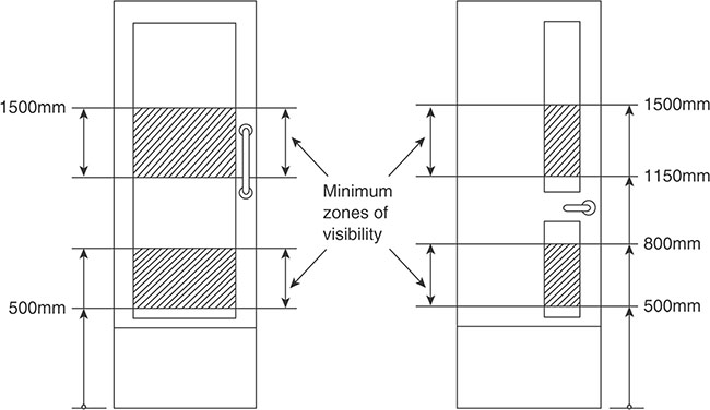
Figure 7.12.6 Visibility requirements of doors
• Upward-opening doors and gates are fitted with a device to stop them falling. |
K 10.1c |
• Power-operated doors and gates include safety features (e.g. a power switch that is operated by a pressure-sensitive door edge). |
|
• The stop switch is readily identifiable and accessible. |
|
• In the event of a power failure, the facility for manual or automatic opening is retained. |
K 10.1d |
6.12.2.4.2 Hazards on access routes
• If, during normal use, any door (other than a fire escape door) swings out by more than 100mm towards an access route, it is protected as shown in Figure 7.12.7. |
K 10.2 |
7.12.2.5 Conservation of fuel and power
p.1169
• Thermal bridges should be avoided around door openings. |
L2A 3.3 |
• The exemption from the energy efficiency provisions for extensions consisting of a conservatory or porch only applies where existing doors are retained, or replaced. |
L2B 2 |
• Doors should be incorporated in an extension. |
L2B 4.3 |
• Where the extension is a conservatory or porch, effective thermal separation between the heated area in the existing building, i.e. the doors between the building and the extension, should be insulated and draughtproofed to at least the same extent as in the existing building |
|
• The limitations on total area of windows, roof windows and doors do not apply. |
L2B 4.12 |
• Where an existing door which separates a conditioned space from an unconditioned space or the external environment has a U-value that is worse than 3.3 W/m2K, the guidance in paragraphs 4.23 to 4.28 (below) should be followed. |
|
• For a high-usage entrance door, some lesser provision for energy efficiency may be made. |
L2B 4.19d |
• Where doors are to be provided their performance should be no worse than: |
|
|
|
|
|
|
|
• If a pedestrian door is enlarged or a new one created, then the area of the windows and pedestrian doors and of rooflights expressed as a percentage of the total floor area of the building should not exceed the relevant value from Table 7.12.3. |
|
• If fully glazed external pedestrian doors are unable to meet the requirements because of the need to maintain the external appearance of the façade or the character of the building, such fittings should meet a centre pane U-value of 1.2W/m2K. |
|
|
L2B 4.24 |
• Where enhanced performance requirements require thicker glass to be used, reasonable provision would be demonstrated if the window unit with the equivalent standard glazing thickness can be shown to comply. |
|
• U-values of doors are calculated using the methods and conventions set out in BSE Report BR 4436, and should be based on the whole unit. |
|
• The U-value of the door can be calculated for the standard size as laid out in BS EN 14351-1 or the specific size and configuration of the actual door. |
L2B 4.25 |

Figure 7.12.7 Avoiding doors on access routes
Table 7.12.3 Opening areas in the extension

7.12.2.6 Access to and use of buildings
• Where door-opening furniture projects beyond the face of the door or otherwise creates enhanced differentiation and shade, a minimum difference in light reflectance value of 15 points is considered adequate. |
|
• Wheelchair users should have adequate space to stop and pass through doors without having to reverse into circulation routes or risk rolling back down slopes. |
M2 1.23 |
• The landing at the foot and head of the ramp should be clear of any door swings. |
M2 1.26h |
• Intermediate landings should be clear of any door swings. |
M2 1.26i |
• No doors should swing across landings. |
M2 1.33e |
• Doors in frequent use should have a level threshold. |
M2 2.6 |
• There should be a level landing at least 1500 x 1500mm, clear of any door swings, immediately in front of the entrance. |
M2 2.7d |
• Any door entry systems should be accessible. |
M2 2.7f |
• Weather protection should be provided at manual non-powered entrance doors. |
M2 2.7g |
p.1170
7.12.2.5.1 Doors to accessible entrances
• Doors to the principal, or alternative accessible, entrance should be accessible to all. |
|
• Entrance doors may be manually operated without powered assistance, or power operated under manual or automatic control. |
|
• Entrance doors should be capable of being held closed when not in use. |
M2 2.8 |
• A non-powered manually operated entrance door, fitted with a self-closing device capable of closing the door against wind forces and the resistance of draught seals, is unlikely to be openable by many people, particularly those in a wheelchair or with limited strength. |
M2 2.9 |
• A powered door opening and closing system, either manually controlled or automatically operated by sensors, is the most satisfactory solution for most people. |
M2 2.10 |
• An automatic sliding door may be used. |
|
• Once open, all doors to accessible entrances should be wide enough to allow unrestricted passage for a variety of users. |
![]() Double buggies are wider than wheelchairs and this should be borne in mind when determining an appropriate effective clear width for an entrance door to certain buildings.
Double buggies are wider than wheelchairs and this should be borne in mind when determining an appropriate effective clear width for an entrance door to certain buildings.
• In some circumstances, in existing buildings it will not be practicable or cost effective to adopt the preferred effective clear widths for new buildings. |
M2 2.11 |
• It should be possible to see someone approaching from the opposite direction (except for reasons of privacy or security). |
M2 2.12 |
• Self-closing doors to accessible entrances should have a power-operated door when it appears that it will not be possible otherwise for a person to open the door. |
|
• Doors to accessible entrances should ensure the effective clear width through a single leaf door, or one leaf of a double leaf door, is in accordance with Table 7.12.3. |
|
• Doors to accessible entrances should be installed in accordance with Approved Document K, Section 10. |
M2 2.13 |
Note: The effective clear width is the width of the opening measured at right angles to the wall in which the door is situated from the outside of the door stop on the door closing side to any obstruction on the hinge side, whether this be projecting door opening furniture, a weather board, the door or the door stop. For specific guidance on the effective clear widths of doors in sports accommodation, refer to Sport England’s ‘Accessible Sports Facilities’ (www.sportengland.org/media/4508/accessible-sports-facilities-2010.pdf).
Table 7.12.4 Minimum effective clear widths of doors

7.12.2.5.2 Internal doors
• If internal doors are required the use of self-closing devices should be minimized. |
M2 3.7 |
• Low energy powered door systems may be used in locations not subject to frequent use or heavy traffic as the opening and closing action is relatively slow. |
|
• The presence of doors, whether open or closed, should be apparent. |
M2 3.8 |
• Internal doors should comply with the following: |
|
|
|
|
|
|
|
|
|
|
|
|
|
|
|
|
M2 3.10 |
|
|
|
|
|
|
|
|
|
|
|
|
|
• The effective clear width through a door should be in accordance with Table 7.12.3. |
M2 3.10 M2 4.24a M2 4.24k |
• Doors which open towards a major access route or an escape route should be recessed so that they do not project into the corridor space (unless they are for minor utility facilities). |
M2 3.14g |
• Doors from unisex wheelchair-accessible toilets may project into a corridor (if it is not a major access or an escape route) provided the corridor is 1800mm wide at that point. |
M2 3.14h |
• On a major access route or an escape route, the wider leaf of a series of double doors with leaves of unequal width should be on the same side of the corridor for its entire length. |
M2 3.14i |
• An internal lobby should allow a wheelchair user, or a person pushing a pram or buggy, to move clear of one door before attempting to open the second door. |
M2 3.15 |
7.12.2.5.3 Manually operated non-powered entrance doors
Self-closing devices on manually operated non-powered swing doors disadvantage many people who have limited upper body strength, are pushing prams or are carrying heavy objects.
• A space alongside the leading edge of a door should be provided to enable a wheelchair user to reach and grip the door handle, then open the door without releasing hold on the handle and without the footrest colliding with the return wall. |
M2 2.15 |
• Door furniture on manually operated non-powered doors should be easy to operate by people with limited manual dexterity, and be readily apparent against the background of the door. |
M2 2.16 |
• Manually operated non-powered entrance doors will satisfy the requirement if: |
|
|
|
|
|
|
|
|
M2 2.17 |
7.12.2.5.4 Powered entrance doors
• Activation (e.g. motion sensors and push buttons), safety features and the time-lapse allowed for entry and exit through powered door systems should be carefully considered to suit the needs of people who cannot react quickly. |
M2 2.18 |
• Manual controls for powered entrance doors should be clearly distinguishable against the background and not located so that a person, having used the control, needs to move to avoid contact with the door as it opens. |
M2 2.19 |
• Revolving doors are not considered accessible. |
|
• If a revolving door is used, an accessible entrance door should be provided immediately adjacent to it and signed to show that it is accessible. |
M2 2.20 |
• Powered entrance doors should: |
|
|
|
|
|
|
|
|
|
|
|
|
|
|
|
|
|
• Powered door manual controls should be: |
|
|
|
|
|
|
|
|
M2 2.21 |
7.12.2.5.5 Glass doors, screens and entrance lobbies
• People with a visual impairment should be in no doubt as to the location of glass doors. |
|
• There should be a different style of manifestation for the door and any glazed screen. |
M2 2.22 |
• The presence of a door should be apparent when it is shut and when it is open. |
|
• Where it can be held open, steps should be taken to avoid people being harmed by walking into the door. |
M2.2.23 |
• Glass doors and glazed screens should comply with Approved Document K, Section 7. |
M2 2.24 |
• A lobby may make it possible for an external door to have a self-closing device with a lower power size rating than might otherwise be the case. |
M2 2.26 |
• The minimum length of the lobby is related to the size, and projection of the chosen door. |
|
• Where both doors of a lobby are automatic sliding doors, the length can be reduced as no door swings are involved, nor is space required for manual operation. |
|
• If ‘reduced swing’ door sets are used, the length can be reduced. |
M2 2.27 |
• A lobby length with single swing doors is should be in accordance with Figure 7.12.8. |
|
• A lobby length with double swing doors is at least (Door Projection 1 (DP1) + Door Projection 2 (DP2) + 1570mm). |
|
• A lobby width (excluding any projections into the space) is at least 1200mm (or Door Leaf 1 (DL1) or Door Leaf 2 (DL2) + 300mm), whichever is the greater when single leaf doors are used, and at least 1800mm when double leaf doors are used. |
M2 2.29a–c |
• Any reception point should be easily identifiable from the entrance doors. |
M2 3.6b |
7.12.2.5.6 Lifts
• Lift door systems should allow time for people to enter or leave the lift without coming into contact with closing doors. |
M2 3.30 |
• Lift cars and lifting platforms may be provided with opposing doors to allow a wheelchair user to leave without reversing out. |
M2 3.33 M2 3.41 |
• Power-operated horizontal sliding doors should provide an effective clear width of at least 800mm (nominal). |
M2 3.34e |
• Doors should be fitted with timing devices and reopening activators. |
M2 3.34f |
• Lift landing and car doors should be distinguishable visually from the adjoining walls. |
M2 3.34i |
• In some cases, it may be more convenient to provide a second door at 90° to the first, in which case a wider platform would be required. |
M2 3.41 |

Figure 7.12.8 Key dimensions for lobbies with single leaf doors
7.12.2.5.7 Wheelchair accessible bedrooms
• If entrance doors to wheelchair-accessible bedrooms are powered opening, there is no need for a 300mm access space adjacent to the leading edge of the door. |
M2 4.18 |
• Wheelchair users should also be able to visit companions in other bedrooms: |
M2 4.21 |
|
|
|
|
• For people with limited manual dexterity, electronic card-activated locks for bedroom entrance doors and lever taps in sanitary accommodation can be an advantage. |
M2 4.23 |
• Swing doors for built-in wardrobes and other storage systems should open through 180o. |
M2 4.24b |
• Handles on hinged and sliding doors should be easy to grip and operate and contrast visually with the surface of the door. |
M2 4.24c |
• The door from the access corridor to a wheelchair-accessible bedroom should comply with the provisions of ‘internal doors’ (Section 7.12.2.5.2), in particular the maximum permissible opening force, and the need for a clear space of 300mm from the leading edge of the door to the side wall. |
M2 4.24j |
• Wide angle viewers should be located at 1050mm and 1500mm above floor level. |
M2 4.24n |
• A balcony should have a door which complies with Table 7.12.3 (Section 7.12.2.5.2) |
|
• The door threshold to the balcony should be level. |
M2 4.24p |
• There should be no permanent obstructions in a zone 1500mm back from any balcony doors. |
M2 4.24p |
• There should be consistent relationship with doorways for people to manipulate switches. |
|
• Socket outlets should be located consistently in relation to doorways . |
|
• Light switches for use by the general public should align horizontally with door handles within the range 900 to 1100mm, for ease of location when entering a room. |
M2 4.26 |
7.12.2.5.8 Sanitary accommodation
• WC cubicle doors should be operable by people with limited strength or manual dexterity. |
|
• Doors to cubicles should be capable of being opened if a person has collapsed against them while inside the cubicle. |
|
• All doors to WC cubicles and wheelchair accessible unisex toilets should open outwards. |
|
M2 5.3 |
• WC compartment doors, and doors to wheelchair-accessible unisex toilets, changing rooms or shower rooms, should be fitted with light-action privacy bolts so that they can be operated by people with limited dexterity and, if required to self-close, can be opened using a force at the leading edge of not more than 30N from 0° (the door in the closed position) to 30° open, and not more than 22.5N from 30° to 60° of the opening cycle. |
|
• Doors to wheelchair-accessible unisex toilets, changing rooms or shower rooms should have an emergency release mechanism so that they can be opened outwards, from the outside, in case of emergency. |
|
• Doors should not obstruct emergency escape routes when they are open. |
M2 5.4 |
• Doors should open outward and have a horizontal closing bar fixed to the inside face. |
M2 5.10g |
• Standard WC compartments should have a minimum manoeuvring space clear of a door swing. |
M2 5.12 |
• Doors to standard WC compartments within separate-sex toilet washrooms should have a 450mm diameter manoeuvring space which is maintained between the swing of the door, the WC pan and the side wall of the compartment (see Figure 7.12.9). |
M2 5.14a |
• Doors to compartments for ambulant disabled people should be outward opening and have a horizontal closing bar fixed to the inside face. |
M2 5.14c |
• In communal shower and changing facilities, subdivisions that have the same configuration of space and equipment as self-contained facilities should be provided but without doors. |
M2 5.18c |
• Doors should be outward opening and fitted with a horizontal closing bar on the inside face. |
M2 5.21e |

Figure 7.12.9 WC cubicle for ambulant disabled people
7.13 Access routes to, from and within buildings
7.13.1 Requirements
This section provides the details for buildings other than dwellings only where they differ from the requirements already given in Chapter 6.13.


Note: Access lobbies and corridors are also covered in Chapter 7.14.
![]() Note: Approved Documents B2 (Fire safety) and M2 (Access to and use of buildings) apply specifically to buildings other than dwellings.
Note: Approved Documents B2 (Fire safety) and M2 (Access to and use of buildings) apply specifically to buildings other than dwellings.
7.13.2 Meeting the requirement
7.13.2.1 Fire safety
7.13.2.1.1 General
• People should be able to gain access to buildings and use their facilities, both as visitors and as people who live or work in them. |
B2 0.19 |
• The fire safety measures incorporated into a building should take account of the needs of all those persons who may have access to the building. |
|
• It is not appropriate to presume that certain groups of people will be excluded from a building because of its use. |
B2 0.19 |
• Access requirements increase with building size and height. |
B2 16.1 |
• The need for easy and rapid evacuation of a building in case of fire may conflict with the control of entry and exit in the interest of security. |
B2.x |
• Measures intended to prevent unauthorised access may hinder entry of the fire and rescue service to rescue people trapped by fire. |
|
• Particular care should be taken with interfaces with access control systems. |
B2 1.38 |
• The head of the access stair should be no further than 7.5m from any point on a gallery. |
B2 2.8c |
• Every part of each storey in a multistorey building should have access to more than one stair. |
B2 3.3 |
• Any measures that restrict access to or within the building should not adversely affect fire safety provisions. |
B2 3.7 |
• An inner room is at risk if a fire starts in its access room this is acceptable if: |
|
|
|
|
Table 7.13.1 Limitations on travel distance


|
B2 3.10 |
• In larger buildings, provision should be made for access by fire and rescue services. |
B2 4.3 |
• All doors providing access to an external escape stair should be fire-resisting and self-closing. |
B2 5.25a |
• Access to refuse storage chambers should not be adjacent to escape routes or final exits, or near to windows of flats. |
B2 5.57 |
• Final exits should provide direct access to a street, passageway, walkway or open space. |
B2 5.31 |
• Final exits should not present an obstacle to users. |
|
• Where a final exit is accessed without the need to first traverse steps then a level threshold and ramp should be provided. |
B2 5.32 |
• All escape routes should have adequate artificial lighting. |
B2 5.36 |
• Roller shutters across a means of escape should only be released by a heat sensor. |
|
• Closure of shutters in such locations should not be initiated by smoke detectors or a fire alarm system, unless the shutter is forms part of a boundary to a smoke reservoir. |
B2 AppB.6 |
7.13.2.1.2 Flats
• All habitable rooms in the upper storey of a multistorey flat should have direct access to an internal protected stairway leading to a final exit. |
|
• A single window may serve two rooms as long as they each have their own access to a stair. |
|
• A communicating door between the rooms must be provided. |
B2 2.12b |
• An inner room is at risk if a fire starts in its access room. This is acceptable if: |
|
|
|
|
|
|
|
• An alternative exit from a flat may lead to a final exit or common stair by way of: |
|
|
|
|
B2 2.17 |
• Flats should have access to alternative escape routes (as shown in Figure 7.13.1 and Section 6.12). |
B2 2.20 |
• Smoke vents in a single-stair building should be actuated by means of smoke detectors in the common access space. |
B2 2.26 |
• The door to a common corridor should be positioned so that smoke will not affect access to more than one stairway. |
B2 2.28 |
• A single access stair may be external if it serves a floor not more than 6m above the ground level and has some means of ventilation. |
B2 2.48 |
• Where there is more than one escape stair, it should not be necessary to pass through one stairway to reach another. |
|
• It is acceptable to pass through a stairway’s protected lobby to reach another stair. |
B2 3.13 |
• A corridor more than 12m long that provides access to alternative escape routes should be subdivided by self-closing fire doors (and any necessary associated screens). |
B2 3.26 |
• A dead-end portion of a corridor that provides access to a point from which alternative escape routes are available should be separated by self-closing fire doors. |
B2 3.27 |
• Refuges should provide an area accessible to a wheelchair of at least 900mm x 1400mm in which a wheelchair user can await assistance. |
|
• If the wheelchair space is within a protected stairway, the wheelchair space should not obstruct the flow of persons escaping (see Figure 7.13.3). |
B2 4.9 |
• Fixed ladders should not be used as a means of escape for members of the public but may be used to access to plant rooms that are not normally occupied. |
B2 5.22b |

Figure 7.13.1 Flats served by one common stair
7.13.2.1.3 Access and facilities for the fire service
• Firefighters will need special access facilities equipped with fire mains for deep basements and tall buildings. |
|
• Fire appliances will need access to entry points near a fire mains. |
B5ii |
• Depending on the size of the building, vehicle access may be required to the perimeter. |
|
• Small buildings should be sufficiently close to a point accessible to fire and rescue service vehicles. The less onerous of the following two options should be selected: |
|
|
|
|
|
• In taller blocks of flats, fire and rescue service facilities are required within the building. |
|
• Products of combustion from basement fires tend to escape via stairways, making access difficult for fire and rescue service personnel. |
|
• Fire mains may be provided in buildings where vehicle access is not provided. |
B2 15.3 |
• Where no piped water supply is available, a spring, river, canal or pond may be used, provided that access, space and a hard standing are available for a pumping appliance. |
B2 15.8 |
• There should be vehicle access for a pump appliance to blocks of flats to within 45m of all points within each dwelling. |
B2 16.3 |
• Buildings that do not have fire mains should provide access for vehicles in accordance with Table 7.13.2. |
B2 16.1 |
Table 7.13.2 Fire and rescue service vehicle access to buildings other than dwellings


Figure 7.13.2 Refuge formed in a protected stairway
7.13.2.1.2 Vehicle access routes
• Every elevation to which there is vehicle access should have a suitable door (no less than 750mm wide) that provides access to the interior of the building. |
B2 16.5 |
• Pumping appliance access should be within 18m of each dry fire main inlet connection point. |
|
|
B2 16.6 |
• Pumping appliance access should be to within 18m and within sight of a suitable entrance giving access to a wet main. |
|
|
B2 16.7 |
• Vehicle access routes should meet the standards in Table 7.13.3. |
B2 16.8 |
• Where access is provided to an elevation in accordance with Table 7.13.2: |
|
|
|
|
|
|
|
B2 16.9 |
• In areas provided for high-reach appliances, overhead obstructions should be avoided in the zone shown in Figure 7.13.3. |
B2 16.10 |
Table 7.13.3 Typical fire and rescue vehicle access route specification


Figure 7.13.3 Relationship between building and hardstanding/access road
• Turning facilities should be provided in any dead-end access route that is more than 20m long (see section 6.13 for more details). |
|
• This can be by a hammerhead or turning circle. |
B2 16.11 |
• In low-rise buildings, a combination of the normal means of escape and measures for vehicle access which facilitate ladder access to upper storeys should be provided. |
B2 17.1 |
7.13.2.1.3 Ventilation
• Access should be provided to allow inspection, testing and maintenance of both the fire damper and its actuating mechanism. |
B2 10.12 |
• Each compartment in a basement should have direct access to venting, without having to open doors etc. into another compartment. |
B2 18.3 |
• If the natural smoke outlet terminates at a point that is not readily accessible, it should be kept unobstructed and should only be covered with a non-combustible grille or louvre. |
B2 18.10 |
7.13.2.2 Conservation of fuel and power
• Vehicle access and similar large doors have a U-value of 1.5W/m2K. |
L2B Table 3 |
7.13.2.3 Access to and use of buildings
• Access routes should not be too narrow as this can make it difficult for people to pass each other. |
M2 1.2 M2 3.11 |
• Potential hazards on access routes adjacent to buildings should be avoided. |
M2 1.5 |
• All access routes to principal, or alternative accessible, entrances should have a surface that people are able to travel along easily without the risk of tripping or falling. |
M2 1.9 |
• If there are different materials on an access route, they should have similar frictional characteristics. |
M2 1.13e |
• Separate pedestrian routes should be provided. |
|
• A buff-coloured blister surface should identify an uncontrolled crossing point across the vehicular route. |
M2 1.13h |
• The surface of a parking bay designated for disabled people should allow the safe transfer of a passenger or driver to a wheelchair and transfer from the parking bay to the access route to the building without undue effort, barriers to wheelchairs or hazards from tripping. |
M2 1.15 |
• Handrails should not project into an access route. |
M2 1.37e |
• Features of a building that obstruct an access route should not present a hazard to building users. |
M2 1.38 |
• Powered doors should not project into any adjacent access route. |
M2 3.14 |
• A door that opens towards a corridor which is a major access route or an escape route should be recessed so that, when fully open, it does not project into the corridor space. |
M2 3.14g |
• A door from a unisex wheelchair-accessible toilet may project when open into a corridor that is not a major access route or an escape route, provided the corridor is at least 1800mm wide at that point. |
M2 3.14h |
• On a major access or escape route, the wider leaf of a series of double doors with leaves of unequal width is on the same side of the corridor throughout the length of the corridor. |
M2 3.14i |
• There should be an unobstructed manoeuvring space of 1500mm × 1500mm, or a straight access route 900mm wide, in front of each lifting device. |
M2 3.28a |
• Stepped access routes to audience seating should be provided with fixed handrails. |
M2 4.12 |
• Floor, wall and ceiling surface materials and finishes should help visually impaired people appreciate the boundaries of rooms or spaces and identify access routes. |
M2 4.33 |
7.14 Corridors and passageways
7.14.1 Requirements
This section provides the details for buildings other than dwellings only where they differ from the requirements already given in Chapter 6.16.


![]() Note:
Note:
1. Approved Documents B2 (Fire safety) and M2 (Access to and use of buildings) apply specifically to buildings other than dwellings.
2. Approved Document P (Electrical Safety) only applies to dwellings.
7.14.2 Meeting the requirement
7.14.2.1 Fire safety
![]() Authors’ note: You should be aware that not all corridors need fire protection. The situations where 30 minutes of fire protection is compulsory in a corridor are where bedrooms are accessed from the corridor or where the corridor is a dead end.
Authors’ note: You should be aware that not all corridors need fire protection. The situations where 30 minutes of fire protection is compulsory in a corridor are where bedrooms are accessed from the corridor or where the corridor is a dead end.
7.14.2.1.1 Protected stairways passages and corridors
• Protected stairways should discharge either directly to a final exit or via a protected exit passageway to a final exit. |
|
• Any protected passageway should have the same standard of fire resistance and protection as the stairway it serves. |
B2 2.38 B2 4.36 |
• Where exit passageways leading to different final exits are adjacent, they should be separated by an imperforate enclosure. |
B2 2.39 B2 4.37 |
• An alternative exit from a flat should: |
|
|
|
|
|
|
|
|
|
|
|
|
|
|
B2 2.17 |
• If there is more than one escape stair from an upper storey of a building (or part of a building), only one of the stairs serving the upper storeys of the building (or part) need be terminated at ground level. |
|
• Other stairs may connect with the basement storey(s) if there is a protected lobby, or a protected corridor between the stair(s) and accommodation at each basement level. |
B2 4.43 |
• A door that opens towards a corridor or a stairway should be sufficiently recessed to prevent its swing from encroaching on the effective width of the stairway or corridor. |
B2 5.16 |
![]() Authors’ note: Corridors that connect two or more storey exits or exceed 12m will require a subdividing door.
Authors’ note: Corridors that connect two or more storey exits or exceed 12m will require a subdividing door.
![]() Note: Sprinklers need only be provided within individual flats; they are not required in the common areas.
Note: Sprinklers need only be provided within individual flats; they are not required in the common areas.
7.14.2.1.2 Escape routes
• A single escape route from the flat entrance door is acceptable if: |
|
|
|
|
|
|
B2 2.20 |
• It is acceptable for there to be no alternative at the beginning of the route, provided that the overall distance to the nearest storey exit is within the limits for routes where there is an alternative, and the ‘one direction only’ section of the route does not exceed the limit for travel where there is no alternative (see Table 7.14.1). |
B2 3.6 |

Figure 7.14.1 Flats served by one common stair
• A flat situated in a dead-end part of a common corridor served by two (or more) common stairs should have a travel distance that complies with the limitations in Table 7.14.1 on escape in one direction only (see Figure 7.14.2). |
B2 2.20 |
Table 7.14.1 Limitations on travel distance

• In small single-stair buildings, a single stair may be used, provided that the stair does not serve ancillary accommodation, unless the ancillary accommodation is separated from the stair by a protected lobby, or corridor, which has not less than 0.4m2 permanent ventilation or is protected by a mechanical smoke-control system. |
B2 2.21 |
• The common corridors in flats should be protected corridors. |
B2 2.24 |
• The wall between each flat and the corridor should be a compartment wall. |

Figure 7.14.2 Flats served by more than one common stair
• There should be some means of ventilating common corridors/lobbies. |
B2 2.25 |
• Corridors or lobbies adjoining a stair should be provided with a vent. |
|
• The vent from the corridor/lobby should be located as high as practicable and the top edge should be as high as the top of the door to the stair. |
|
• The minimum free area of the vent from the corridor/lobby into the shaft at the opening at the head of the shaft and at all internal locations within the shaft (e.g. safety grilles) should be at least 1.0m2. |
B2 2.26bii |
• On detection of smoke in the common corridor/lobby, the vent(s) on the fire floor, the vent at the top of the smoke shaft and the vent to the stairway should all open simultaneously. |
|
• The vents from the corridors/lobbies on all other storeys should remain closed. |
B2 2.26biv |
• Mechanical ventilation to the stair and/or corridor/lobby may be provided to protect the stair(s) from smoke. |
|
• Guidance on smoke-control systems using pressure differentials is available in BS EN 12101-6. |
B2 2.27 |
• A common corridor connecting two or more storeys exits should be subdivided by a self-closing fire door with any associated fire-resisting screen (see Figure 7.14.2). |
|
• Doors should be positioned so the smoke does not affect more than one stairway. |
B2 2.28 |
• A dead-end portion of a common corridor should be separated from the rest of the corridor by a self-closing fire door with, if necessary, a fire-resisting screen (see Figures 7.14.1 and 7.14.2). |
B2 2.29 |
• Stores or ancillary accommodation should not be located within, or entered from, any protected lobby or protected corridor which is part of the only common escape route. |
B2 2.30 |
• Where there is more than one escape stair from an upper storey of a building, only one of the stairs serving the upper storeys of the building should terminated at ground level. |
|
• Stairs may connect with the basement storey(s) if there is a protected lobby or a protected corridor between the stair(s) and accommodation at each basement level. |
B2 2.45 |
• A common stair which does not form part of the only escape route from a flat may also serve ancillary accommodation if it is separated from accommodation by a protected lobby or a protected corridor. |
|
• If a stair serves an enclosed (non-open-sided) car park, or place of special fire hazard, the lobby or corridor should have not less than 0.4m2 permanent ventilation or have a mechanical smoke-control system. |
B2 2.47 |
• Buildings with more than one exit in a central core should be planned so that storey exits are remote from one another and so that no two exits are approached from the same lift hall, common lobby or undivided corridor, or linked by any of these. |
B2 3.11 |
• Doors to a protected stairway should be fitted with an automatic release mechanism the stairway. |
B2 3.14 |
• Unless the exit doors have an automatic release mechanism, a passageway should not form part of a primary circulation route. |
|
• A common corridor that serves as a means of escape should be a protected corridor, or a suitable automatic fire detection and alarm system should be installed. |
B2 3.16b |
7.14.2.1.3 Protected corridors and enclosures
• Protected corridors should be provided for the following situations: |
|
|
|
|
|
|
B2 3.24 |
• If a corridor is used as a means of escape, but is not a protected corridor, and is enclosed by partitions, those partitions should be carried up to the soffit of the structural floor above, or to a suspended ceiling. |
|
• Openings into rooms from the corridor should be fitted with doors, which need not be fire doors. |
B2 3.25 |
• Every corridor more than 12m long which connects two or more storeys exits, should be subdivided by self-closing fire doors where necessary. |
|
|
|
p.1171 |
|
|
|
B2 3.26 |

Figure 7.14.3 Subdivision of corridors
• Lobbies or corridors should be enclosed to at least a 30-minute standard. |
B2 8.38c |
• As shown in Figure 7.14.4 every dead-end corridor exceeding 4.5m in length should be separated by self-closing fire doors from any part of the corridor which: |
|
|
|
|
B2 3.27 |
• Figure 7.14.4 shows an example of a dead-end condition in an open storey layout. |
B2 3.6 |
• Cavity barriers may be required where corridors are subdivided. |
B2 9.6 |
• There is no need to add a firefighting lobby between the firefighting stair(s) and a protected corridor or lobby where the Approved Document has been followed. |
• A firefighting lift may open directly into a protected corridor or lobby. |
|
• Firefighting lift landing doors should not be more than 7.5m between the door and firefighting stair. |
B2 17.14 |

Figure 7.14.4 Dead-end corridors
7.14.2.1.4 Residential care home bedrooms
• Each bedroom should be enclosed in fire-resisting construction with fire-resisting doors. |
|
• Every corridor serving bedrooms should be a protected corridor. |
B2 3.48 |
7.14.2.1.5 Access lobbies and corridors
• An escape stair needs a protected lobby or protected corridor when: |
|
|
|
|
|
|
|
|
|
|
|
• A smoke-control system may be used. |
B2 4.34 |
• A protected lobby is required between an escape stairway and a place of special fire hazard. |
|
• A lobby should have not less than 0.4m2 permanent ventilation, or be protected by a mechanical smoke-control system. |
B2 4.35 |
7.14.2.1.6 Refuges
• A protected lobby or protected corridor is a satisfactory refuge. |
B2 4.8 |
• Each refuge should provide an area of at least 900mm x 1400mm in which a wheelchair user can await assistance. |
|
• Where a refuge is a protected lobby or protected corridor, the wheelchair space should not reduce the width of the escape route. |
B2 4.9 |
7.14.2.1.7 Exits
• A firefighting lift may open directly into a protected corridor or lobby. |
|
• Firefighting lift landing doors should not be more than 7.5m between the door and firefighting stair. |
B2 17.14 |
• Every protected stairway should discharge: |
|
|
|
|
B2 4.36 |
![]() Note: Protected exit passageways should have the same standard of fire resistance and lobby protection as the stairway they serve.
Note: Protected exit passageways should have the same standard of fire resistance and lobby protection as the stairway they serve.
• Vision panels are required where doors on escape routes subdivide corridors, or where any doors are hung to swing both ways. |
B2 5.17 |
• In basements and enclosed (non-open-sided) car parks, the lift should be approached only by a protected lobby/corridor, unless it is within a protected stairway. |
B2 5.43 |
• Revolving doors, automatic doors and turnstiles should not obstruct the passage of persons escaping. |
B2 5.18 |
• Final exits should be sited to ensure rapid dispersal of persons from the vicinity of the building so that they are no longer in danger from fire and smoke. |
|
• Direct access to a street, passageway, walkway or open space should be available. |
|
• The route clear of the building should be well defined and have suitable guarding. |
B2 5.31 |
• The width of: |
|
|
|
|
B App B.4 |

Figure 7.14.5 Measurement of door width
• An exit passageway is a protected passageway connecting a protected stairway to a final exit. |
|
• Exit passageways should be protected to the same standard as the stairway they serve. |
B App E |
• In corridors, lobbies or stairways the combustible content should be restricted. |
B2 B1iii |
• There are three categories of system: |
|
|
|
|
|
|
|
• Category L systems are subdivided into L4 – systems installed within those parts of the escape routes comprising circulation areas and circulation spaces, such as corridors and stairways. |
B2 10.30 |
• Table 7.14.2 shows where escape lighting is required on escape routes. |
B2 Table 9 |
Table 7.14.2 Provision for escape lighting

7.14.2.2 Access to and use of buildings
7.14.2.2.1 Design considerations
• Corridors and passageways should be wide enough to allow people with buggies, people carrying cases or people on crutches to pass others on the access route. |
|
• Wheelchair users should have access to adjacent rooms and spaces, be able to pass other people and, where necessary, turn through 180°. |
|
• Corridors narrower than indicated in this guidance, or localised narrowing (e.g. at archways), might be permitted in existing buildings or in some extensions. |
M2 3.11 |
• There should be a visual contrast between walls and ceilings and between walls and floors. |
|
• Attention to surface finishes should be coupled with good natural and artificial lighting. |
M2 3.12 |
• Good acoustic design should be employed to achieve an acoustic environment that is neither too reverberant nor too absorbent. |
M2 3.13 |
7.14.2.2.2 General provisions
Corridors and passageways should comply with the following:
• Columns, radiators and fire hoses should not project into the corridor or, where this is unavoidable, a means of directing people around them, such as a visually contrasting guard rail, should be provided. |
|
• There should be an unobstructed width along their length of at least 1200mm. |
|
• In areas where there is an obstruction there should be passing places at least 1800mm long and the corridor should have an unobstructed width of at least 1800mm at reasonable intervals to allow wheelchair users to pass each other. |
|
• The floor should be level or predominantly level (with a gradient no steeper than 1:60), with any section with a gradient of 1:20 or steeper designed as an internal ramp and in accordance with Figure 7.14.6. |
|
• Where a section of the floor has a gradient, in the direction of travel, steeper than 1:60 but less steep than 1:20, it rises no more than 500mm without a level rest area at least 1500mm long (with a gradient no steeper than 1:60). |
|
• Any sloping section should extend the full width of the corridor. |
|
• If a sloping section does not extend the full width, the exposed edge should be clearly identified by visual contrast and protected by guarding. |
|
• Any door opening towards a major access route or an escape route should be recessed so that, when fully open, it does not project into the corridor space, except where the doors are to minor utility facilities e.g. small store rooms. |
• Any door from a unisex wheelchair-accessible toilet may open into a corridor that is not a major access route or an escape route, provided the corridor is at least 1800mm wide at that point. |
|
• On a major access route or an escape route, the wider leaf of a series of double doors with leaves of unequal width is on the same side of the corridor throughout the length of the corridor. |
|
• Patterns that could be mistaken for steps or changes of level should be avoided. |
|
• Floor finishes should be slip resistant. |
|
• Any glazed screens should comply with Approved Document K. |
M2 3.14 |
Table 7.14.3 Maximum rise and gradient of flights


Figure 7.14.6 Relationship of ramp gradient to the going of a flight
![]() Note: In school buildings where there are lockers within the corridor, the preferred corridor width dimension is 2700mm.
Note: In school buildings where there are lockers within the corridor, the preferred corridor width dimension is 2700mm.
7.14.2.2.3 Internal lobbies
• An internal lobby should allow a wheelchair user or a person pushing a pram or buggy to move clear of one door before attempting to open the second door. |
M2 3.15 |
p.1172
• Internal lobbies should comply with the following: |
|
|
|
|
|
|
|
|
|
|
M2 3.16 |
|
|
|
7.14.2.2.4 Vertical circulation within the building
• A passenger lift is the most suitable means of vertical access and should be provided wherever possible. |
M2 3.17 M 3.21 |
• A sign identifying the floor reached should be provided on each landing in a location that can be easily seen from the lifting device and is designed so that it contrasts visually with its surrounding. |
M2 3.18 |
• A ramp may also be provided on an internal circulation route to a suitable lifting device, if a change of level is unavoidable. |
M2 3.20 |
• For existing buildings, and in exceptional circumstances for new developments with particular constraints where a passenger lift cannot be accommodated, a vertical lifting platform (platform lift), although not equivalent to a passenger lift, may be considered as an alternative option to provide access for persons with impaired mobility. |
M2 3.22 |
• New developments should have a passenger lift serving all storeys. |
M2 3.24 |
• All bedrooms should have an effective clear width of the door from the access corridor that complies with Table 7.14.4. |
|
• The door from the access corridor to a wheelchair-accessible bedroom should comply with the relevant provisions of ‘internal doors’ (see 3.10 of Approved Document M2), in particular the maximum permissible opening force, Table 7.14.4 and the need for a clear space of 300mm from the leading edge of the door to the side wall. |
M2 4.24a M2 4.24j |
Table 7.14.4 Minimum effective clear widths of doors

p.1173
7.15 Sanitary accommodation, bathrooms and showers
7.15.1 Requirements
This section provides the details for buildings other than dwellings only where they differ from the requirements already given in Chapter 6.15.


![]() Note:
Note:
1. Approved Documents B2 (Fire safety), L2B (Conservation of fuel and power) and M2 (Access to and use of buildings) apply specifically to buildings other than dwellings.
2. Approved Document P (Electrical Safety) only applies to dwellings.
p.1174
7.15.2 Meeting the requirement
7.15.2.1 Fire safety
• A suitable method of warning (e.g. a visual and audible fire alarm signal) should be provided in sanitary accommodation that may be used by people with impaired hearing. |
B2 1.34 |
• Sanitary accommodation or washrooms may be in a protected stairway provided that the accommodation is not used as a cloakroom. |
|
|
|
• Sanitary accommodation and washrooms may be included in protected shafts. |
B2 8.36 |
• Smoke alarms should not be fixed in bathrooms or showers. |
B2 1.16 |
• A bathroom, WC or shower room may be an inner room with the only escape route through another room. |
B2 2.5 |
• The maximum distance of travel distance within the room applies within the bedroom and any associated bathroom and is measured to the door of the protected corridor serving the room or suite. |
B Table 2 |
p.1175
7.15.2.2 Ventilation
All office sanitary accommodation and washrooms shall be provided with intermittent air extract ventilation.
• PSVs should be located in the ceiling of a room. |
F Table 5.2 |
• Office sanitary accommodation and washrooms should have an air extract rate of: |
|
|
|
|
F Table 5.2 |
7.15.2.3 Conservation of fuel and power
• A fixed electric heater or mechanical extractor fan in a bathroom is a non-notifiable service. |
L2B 3.30b |
7.15.2.4 Access to and use of buildings
• If sanitary conveniences are provided in any building that is to be extended, the extension should include sanitary conveniences. |
|
• This requirement does not apply if there is provision elsewhere in the building, as long as people from the extension can gain access to and use those conveniences. |
M2 0.8 |
• People should be able to gain access to and to use new or altered sanitary conveniences. |
M2 0.9 |
p.1176
7.15.2.4.1 En-suite facilities in hotels
• En-suite sanitary facilities should be provided for wheelchair-accessible bedrooms. |
|
• In student accommodation, a wheelchair-accessible toilet should be available for disabled visitors. |
|
• An example of a wheelchair-accessible bedroom layout is shown in Figure 7.15.1. |
M2 4.17 M2 4.19 |

Figure 7.15.1 Example of wheelchair-accessible hotel bedroom with en-suite
• Wheelchair users should be able to gain access to and use sanitary accommodation. |
|
• There should be at least as many en-suite shower rooms as en-suite bathrooms. |
|
• Where possible an en-suite shower room or bathroom should have a finger-rinse basin adjacent to the WC as well as a wash basin. |
M2 4.19 |
• Electronic card-activated locks may be used for bedroom entrance doors and lever taps used in sanitary accommodation. |
M2 4.23 |
• Suitable sanitary accommodation should be available to everybody, including sanitary accommodation designed for wheelchair users and ambulant disabled people. |
M2 5.1 |
• When considering sanitary accommodation, the following should be considered: |
|
|
|
|
|
|
|
• People with limited strength or manual dexterity should be able to operate taps and WC cubicle doors. |
|
• Doors to cubicles should be able to be opened if a person inside has collapsed against them. |
|
• It is preferred that WC cubicle and wheelchair-accessible unisex toilet doors open outwards. |
|
• If doors open inwards, the door swing should not encroach into the wheelchair turning space or minimum activity space. |
|
• Where possible, light switches with large push pads should be used. |
M2 5.3 |
• All bath or washbasin taps should be either controlled automatically, or be capable of being operated using a closed fist, e.g. by lever action. |
|
• Terminal fittings should comply with guidance in SI 1999/1148. |
|
• Door handles and ironmongery should comply with the Approved Documents. |
|
• WC compartment doors, and doors to wheelchair-accessible unisex toilets, changing rooms or shower rooms, should be fitted with light-action privacy bolts so that they can be operated by people with limited dexterity and, if required to self-close, can be opened using a force at the leading edge of not more than 30N from 0° (the door in the closed position) to 30° open, and not more than 22.5N from 30° to 60° of the opening cycle. |
|
• WC compartment doors, and doors to wheelchair-accessible unisex toilets, changing rooms or shower rooms, should have an emergency release mechanism so that they are capable of being opened outwards, from the outside, in case of emergency. |
M2 5.4 |
• Doors, when open, should not obstruct emergency escape routes. |
|
• Fire alarms should emit a visual and audible signal. |
|
• An emergency assistance alarm system should have: |
|
|
|
|
|
|
|
• Any lighting controls should comply with the provisions for switches and controls. |
|
• Any heat emitters should be either screened or have their exposed surfaces kept at a temperature below 43°C. |
|
• The surface finish of sanitary fittings and grab bars should contrast visually with background wall and floor finishes. |
|
• There should be visual contrast between wall and floor finishes. |
7.15.2.4.2 Provision of toilet accommodation
• Toilet accommodation should be suitable for all people who use the building. |
|
• Suitable toilet accommodation for disabled people may take the form of: |
|
|
|
|
|
• For wheelchair users, a self-contained unisex toilet is the preferred option. |
|
• Wheelchair-accessible unisex toilets should always be provided as well as wheelchair-accessible accommodation in separate-sex toilet washrooms. |
|
• Wheelchair-accessible unisex toilets should not be used for baby changing. |
M2 5.5 |
• In large building developments, separate facilities for baby changing and an enlarged unisex toilet incorporating an adult-changing table are desirable. |
M2 5.6 |
|
![]() Note: Specific guidance on sanitary accommodation for sports buildings is available in the document ‘Accessible Sports Facilities’ which is available from Sport England (www.sportengland.org/media/4508/accessible-sports-facilities-2010.pdf).
Note: Specific guidance on sanitary accommodation for sports buildings is available in the document ‘Accessible Sports Facilities’ which is available from Sport England (www.sportengland.org/media/4508/accessible-sports-facilities-2010.pdf).
• If there is only space for one toilet in a building, it should be a wheelchair accessible unisex type with greater width to accommodate a standing height wash basin. |
|
• At least one wheelchair-accessible unisex toilet should be provided at each location where sanitary facilities are provided for use by customers and visitors or people working in the building. |
|
• At least one WC cubicle should be provided in separate-sex toilet accommodation for use by ambulant disabled people. |
|
• Where there are four or more WC cubicles in separate-sex toilet accommodation, one of these should be an enlarged cubicle for use by people who need extra space. |
M2 5.7 |
7.15.2.4.3 Wheelchair-accessible unisex toilets
• Wheelchair users should be able to approach, transfer to and use the sanitary facilities in a building. |
|
• A wheelchair-accessible unisex toilet should be provided. |
|
• The relationship of the WC to the finger-rinse basin and other accessories should allow a person to wash and dry hands while seated on the WC. |
|
• The space should allow wheelchair users to adopt various transfer techniques (independent or assisted). |
|
|
|
• The transfer space alongside the WC should be kept clear to the back wall. |
M2 5.8 |
• A unisex toilet should be approached separately from other sanitary accommodation. |
|
• A unisex toilet is more easily identified than a wheelchair-accessible cubicle in a separate-sex toilet washroom and is more likely to be available when required. |
|
• The time taken to reach a wheelchair-accessible toilet should be kept to a minimum. |
|
• A unisex toilet should enable one or two assistants of either sex to assist a disabled person. |
|
• A chemical sanitary waste disposal unit may be required in wheelchair-accessible WC accommodation. |
|
• For wheelchair users who find it difficult to use a standard height WC seat, the WC pan should be able to accept a variable height toilet seat riser (WC pans manufactured in accordance with BS EN 997 would be acceptable). |
M2 5.9 |
![]() Note: BS 8300 contains detailed guidance on techniques used to transfer from a wheelchair to a WC as well as appropriate sanitary and other fittings.
Note: BS 8300 contains detailed guidance on techniques used to transfer from a wheelchair to a WC as well as appropriate sanitary and other fittings.
• A wheelchair-accessible unisex toilet should: |
|
|
|
|
|
|
|
|
|
|
|
|
|
|
|
|
|
|
|
|
|
|
|
|
|
|
|
|
|
|
|
|
|
|
|
|
|
|

Figure 7.15.2 Unisex wheelchair-accessible toilet with corner WC

Figure 7.15.3 Heights and arrangements of fittings in a unisex wheelchair-accessible toilet
p.1177
7.15.2.4.4 Toilets in separate-sex washrooms
• Ambulant disabled people should be able to use a WC compartment in a separate-sex toilet washroom. |
|
• A compartment for ambulant disabled people should be fitted with support rails, and include a minimum activity space to accommodate people with crutches, or impaired leg movements. |
|
• The WC pan should be able to accept a variable height toilet seat riser. |
M2 5.11 |
• An enlarged WC cubicle should be provided for use by people who need extra space. |
|
• A fold-down table, e.g. for baby changing, should be considered. |
|
• A minimum manoeuvring space should be clear of any door swing. |
M2 5.12 |
• In a separate-sex toilet washroom, wheelchair users should be able to use both a urinal and a washbasin at a lower height than is provided for other users. |
|
|
M2 5.13 |
![]() A low-level urinal may be required for children in male washrooms.
A low-level urinal may be required for children in male washrooms.
![]() Note: More detailed guidance on appropriate sanitary and other fittings is given in BS 8300.
Note: More detailed guidance on appropriate sanitary and other fittings is given in BS 8300.
• WC compartments within separate-sex toilet washrooms should: |
|
|
|
|
|
|
M2 5.14 |
|
|
|
|
|
|
|

Figure 7.15.4 WC cubicle for ambulant disabled people
7.15.2.4.5 Wheelchair-accessible changing and shower facilities
In buildings where changing facilities are associated with showering facilities, many disabled people will be content to use changing and shower areas that are open but provided with subdivisions, whereas some will require the privacy and convenience of an individual self-contained cubicle or compartment.
• Where possible, a choice of shower layout should be provided. |
|
• Guidance on en-suite shower facilities for hotel bedrooms is in Section 7.15.2.4.1. |
M2 5.15 |
• A self-contained compartment should allow space for a helper. |
|
• Any combined facility should be divided into ‘wet’ and ‘dry’ areas. |
|
• In open changing and shower areas, it may be difficult to provide a configuration of handrails, controls and seats suitable for all disabled people to use and therefore individual self-contained accommodation is preferred. |
M2 5.16 |
• In individual changing rooms, e.g. in clothes shops, the dimensions and fittings recommended for an individual self-contained changing cubicle should comply with those required in a sports building. |
|
• In large building complexes (e.g. retail parks and large sports centres), one wheelchair-accessible unisex toilet should be provided which is capable of including an adult-changing table. |
![]() Note:
Note:
1. Details of different types of changing and shower facilities sports buildings are given in ‘Accessible Sports Facilities’ (www.sportengland.org/media/4508/accessible-sports-facilities-2010.pdf).
2. Guidance on appropriate sanitary and other fittings is given in BS 8300. M2 5.17
7.15.2.4.5.1 changing and shower facilities
Changing and shower facilities should be provided with the following:
• A choice of layouts suitable for left-hand and right-hand transfer if more than one individual changing or shower compartment is available. |
|
• Wall-mounted drop-down support rails and wall-mounted slip-resistant tip-up seats. |
|
• Subdivisions with the same configuration of space and equipment as for self-contained facilities but without doors, in communal shower and changing facilities. |
M2 5.18 |
• In sports facilities, individual self-contained shower and changing facilities in addition to communal separate-sex facilities. |
• An emergency assistance pull cord which is easily identifiable and reachable from the wall-mounted tip-up seat, or from the floor. |
|
• An emergency assistance alarm system. |
|
• Facilities for limb storage. |
p.1178
7.15.2.4.5.2 changing facilities
• The minimum overall dimensions of, and the arrangement of equipment and controls within, individual self-contained changing facilities should comply with Figure 7.15.5. |
|
• The floor of a changing area should be level and slip resistant when dry or when wet. |
|
• There should be manoeuvring space 1500mm deep in front of lockers. |
M2 5.18 |
p.1179
7.15.2.4.5.3 shower facilities
• Individual self-contained shower facilities should comply with Figure 7.15.6. |
|
• In commercial developments where showers are provided, at least one of them should be a wheelchair-accessible shower compartment. |
|
• The shower curtain should enclose the seat. |
|
• The rails, when in a horizontal position, should be able to be operated from the shower seat. |
|
• A shelf should be provided for toiletries (reached from the shower seat or the wheelchair, before or after transfer). |
|
• The floor of the shower and shower area should be slip-resistant and self-draining. |
|
• A shower terminal fitting should comply with Guidance Note G18.5. |
|
• The markings on the shower control should be logical and clear. |
|
• A wheelchair-accessible shower that is available in communal areas should have shower controls positioned between 750 and 1000mm above the floor. |
M2 5.18 |

Figure 7.15.5 Self-contained changing room for individual use

Figure 7.15.6 Self-contained shower room for individual use
7.15.2.4.5.4 shower facilities incorporating a WC
• Overall dimensions and the arrangement of fittings should comply with Figure 7.15.7. |
|
• A choice of left-hand and right-hand transfer layouts should be available when more than one shower area incorporating a corner WC is provided. |
M2 5.18 |
![]() Note: Guidance prepared by the Health and Safety Executive on the slip resistance of floor surfaces is in Annex C of BS 8300.
Note: Guidance prepared by the Health and Safety Executive on the slip resistance of floor surfaces is in Annex C of BS 8300.

Figure 7.15.7 Shower room incorporating a corner WC for individual use
7.15.2.4.5.5 wheelchair-accessible bathrooms
• Wheelchair users and ambulant disabled people should be able to wash or bathe either independently or with assistance from others. A choice of bathroom layout should be provided wherever possible. |
M2 5.19 |
• The guidance applies to wheelchair-accessible bathing facilities where provided in buildings such as hotels, motels, relatives’ accommodation in hospitals, and to student accommodation and sports facilities where baths are provided as an alternative, or as a supplement, to showers. |
|
• For guidance on the provision of en-suite bathrooms associated with hotel bedrooms, see Section 7.15.2.4.1 |
M2 5.20 |
![]() Note: More detailed guidance on appropriate sanitary and other fittings, including facilities for the use of mobile and fixed hoists is in BS 8300.
Note: More detailed guidance on appropriate sanitary and other fittings, including facilities for the use of mobile and fixed hoists is in BS 8300.
• The minimum overall dimensions of, and the arrangement of fittings within, a bathroom for individual use incorporating a corner WC should comply with Figures 7.15.8 and 7.15.9. |
|
• A choice of layouts for left-hand or right-hand transfer should be provided when more than one bathroom for individual use incorporating a corner WC is available. |
|
• The bathroom floor should be slip resistant when dry or wet. |
|
• The bath should have a transfer seat 400mm deep and equal to the width of the bath. |
|
• Doors should be outward opening and fitted with a horizontal closing bar on the inside face. |
|
• An emergency assistance pull cord should be provided that is easily identifiable and reachable from the bath or from the floor. |
|
• There should be an emergency assistance alarm system. |
M2 5.21 |
![]() Note: Guidance prepared by the Health and Safety Executive on the slip resistance of floor surfaces is given in Annex C of BS 8300.
Note: Guidance prepared by the Health and Safety Executive on the slip resistance of floor surfaces is given in Annex C of BS 8300.

Figure 7.15.8 Bathroom incorporating a corner WC

Figure 7.15.9 Grab rails and fittings associated with a bath
p.1180
7.16 Electrical safety – buildings other than dwellings
7.16.1 Requirements
This section provides the details for buildings other than dwellings only where they differ from the requirements already given in Chapter 6.16.


![]() Note:
Note:
1. Approved Documents B2 (Fire safety), L2A and L2B (Conservation of fuel and power) and M2 (Access to and use of buildings) apply specifically to buildings other than dwellings.
2. Approved Document P (Electrical Safety) only applies to dwellings.
![]() The Workplace (Health, Safety and Welfare) Regulations 1992 also contain some requirements which affect building design and apply to the common parts of flats and similar buildings where cleaners, wardens and caretakers are employed to work.
The Workplace (Health, Safety and Welfare) Regulations 1992 also contain some requirements which affect building design and apply to the common parts of flats and similar buildings where cleaners, wardens and caretakers are employed to work.
p.1181
7.16.2 Meeting the requirement
p.1182
7.16.2.1 Fire safety
7.16.2.1.1 General
• A protected stairway may contain an electricity meter(s). |
B2 2.40 |
• All escape routes should have adequate artificial lighting as shown in Table 7.16.1. |
B2 5.36 |
• Where the concealed space is an undivided area which exceeds 40m, any electrical wiring in the void should be laid in metal trays, or in metal conduit. |
B2 9.12 |
• Roller shutters across a means of escape should only be released by a heat sensor, such as a fusible link or electric heat detector, in the immediate vicinity of the door. |
|
• Closure of shutters over a means of escape should not be initiated by smoke detectors or a fire alarm system, unless the shutter is also intended to partially descend to form part of a boundary to a smoke reservoir. |
B2 AppB.6 |
Table 7.16.1 Provision for escape lighting

p.1183
7.16.2.1.2 Smoke alarms
• The power supply for a smoke alarm system should be derived from mains electricity. |
|
• The mains supply to a smoke alarm should comprise a single independent circuit at the flat’s main distribution board or a single regularly used local lighting circuit. |
|
• A mechanism should be provided to isolate the power to smoke alarms without isolating the lighting. |
B2 1.19 |
• A building should be provided with a suitable electrically operated fire warning system with manual call points sited adjacent to exit doors and sufficient sounders to be clearly audible throughout the building. |
B2 1.29 |
• Electrically operated fire alarm systems should comply with BS 5839-1. |
B2 1.30 |
• Call points for electrical alarm systems should comply with: |
|
|
|
|
|
• Call points should be installed in accordance with BS 5839-1. |
|
• Type B call points should only be used with the approval of the Building Control Body (BCB). |
B2 1.31 |
• Where fire detection or alarm systems control the release arrangements for electrically held-open fire doors and electronically locked exit doors, the interface between the fire detection/alarm system and door system should be designed to achieve a high degree of reliability. |
B2 1.38 |
• Electrically powered locks should return to the unlocked position on: |
|
|
|
|
|
|
|
• If a door provides escape in either direction, a lock unit should be installed on both sides. |
B2 5.11 |
p.1184
7.16.2.1.3 Critical or protected circuits
• Protected circuits are needed where it is critical for electrical circuits to continue to function during a fire. |
p.1185
• Damage to cables forming protected circuits should be limited by: |
|
|
|
|
|
|
|
• Cable supports should be non-combustible and their circuit integrity should not be reduced below that afforded by the cable. |
B2 5.38 |
• A protected circuit should consist of cable meeting at least the requirements for PH 30 classification when tested in accordance with BS EN 50200. |
|
• A protected circuit should follow a route that passes through parts of the building where fire risk is negligible. |
|
• A protected circuit should be separate from any circuit provided for another purpose. |
|
• In a large or complex building fire protection systems may need to operate for an extended period during a fire. |
|
• Further guidance on the selection of cables for such systems is given in BS 5839-1, BS 5266-1 and BS 7346-6. |
p.1186
7.16.2.2 Conservation of fuel and power
• Fixed electric heaters, mechanical extractor fans in a kitchen or bathroom, and room air-conditioning unit,s are non-notifiable services. |
L2A 3.17 |
• Where a renewable energy generator such as a wind turbine or photovoltaic array is replaced, the new system should have an electrical output that is not less than that of the original installation. |
L2B 4.31 |
• The electricity generated by any combined heat and power or trigeneration scheme is always credited at an emission factor equal to the grid average. |
L2A 2.13 |
• CO2 emissions associated with the thermal energy streams of a trigeneration scheme should be attributed in proportion to the output energy streams. |
|
• The Building CO2 Emission Rate submission should be accompanied by a report, signed by a suitably qualified person, detailing how the emission factors have been derived. |
p.1187
7.16.2.2 Access to and use of buildings
• The use of self-closing devices should be minimized (particularly in parts of buildings used by the general public). |
|
• Where closing devices are required for fire control, electrically powered hold-open devices or swing-free closing devices should be used as appropriate. |
M2 3.7 |
p.1188
7.17.1 Requirements
This section provides the details for buildings other than dwellings only where they differ from the requirements already given in Chapter 6.17.


![]() Note: Approved Documents B2 (Fire safety), L2A and L2B (Conservation of fuel and power) and M2 (Access to and use of buildings) apply specifically to buildings other than dwellings.
Note: Approved Documents B2 (Fire safety), L2A and L2B (Conservation of fuel and power) and M2 (Access to and use of buildings) apply specifically to buildings other than dwellings.
7.17.2 Meeting the requirement
7.17.2.1 Fire safety
Fire detection sensors may be sensitive to smoke, heat, gaseous combustion products or radiation. Normally the control and indicating equipment operates a fire alarm system and it may perform other signalling or control functions as well.
• Any hidden voids in the construction should be sealed and subdivided to inhibit the unseen spread of fire and products of combustion. |
B3d |
• Products of combustion from basement fires tend to escape via stairways, making access difficult for fire and rescue service personnel; therefore vents should be provided. |
B5ii(e) |
p.1189
7.17.2.2 Ventilation
The pollutant(s) of most importance will vary between building types (e.g. dwelling, office, factory) and building use. However, combustion products from unflued appliances (e.g. gas, oil or solid fuel cookers) are common pollutants.
• A protected stairway may not contain sanitary accommodation or washrooms with any gas appliance other than a gas water heater or sanitary towel incinerator. |
F 4.38 |
• In order to prevent the by-passing of compartmentation, if a flue, or duct containing flues or appliance ventilation duct(s), passes through a compartment wall or floor, or is built into a compartment wall, each wall of the flue or duct should have a fire resistance of at least half that of the wall or floor. |
F 10.16 |
p.1190
7.17.2.3 Conservation of fuel and power
• Where a biomass heating appliance is supplemented by an alternative appliance (e.g. gas), the CO2 emission factor for the overall heating system should be based on a weighted average for the two fuels based on the anticipated usage of those fuels. |
|
• The Building CO2 Emission Rate submission should be accompanied by a report, signed by a suitably qualified person, detailing how the combined emission factor has been derived. |
L2A 2.11a |
• Where the same appliance is capable of burning both biomass fuel and fossil fuel, the CO2 emission factor for dual-fuel appliances should be used, except where the building is in a smoke-control area, when the anthracite figure should be used. |
|
• Centralised switches should be considered to allow the facilities manager to switch off appliances when they are not needed (e.g. overnight and at weekends). |
|
• To maximize energy savings, centralised switches should be automated (with manual override). |
L2A 2.49 |
• Work on combustion appliances remains notifiable building work. |
L2B 3.29 |
• When replacing a heating appliance, you should consider connecting to any existing local heat networks. |
|
• Work involving pipework changes should consider providing capped-off connections to facilitate subsequent connection to a planned local heat network. |
L2B 4.32 |
p.1191
7.17.2.4 Access to and use of buildings
• Switches for permanently wired appliances should be located between 400mm and 1200mm above the floor, unless needed at a higher level for particular appliances. |
M2 4.30 |
p.1192
7.18.1 Requirements
This section provides the details for buildings other than dwellings only where they differ from the requirements already given in Chapter 6.18.


![]() Note: Approved Documents B2 (Fire safety), L2A and L2B (Conservation of fuel and power) and M2 (Access to and use of buildings) apply specifically to buildings other than dwellings.
Note: Approved Documents B2 (Fire safety), L2A and L2B (Conservation of fuel and power) and M2 (Access to and use of buildings) apply specifically to buildings other than dwellings.
7.18.2 Meeting the requirement
7.18.2.1 Fire safety
Fire detection sensors may be sensitive to smoke, heat, gaseous combustion products or radiation. Normally the control and indicating equipment operates a fire alarm system and it may perform other signalling or control functions as well.
• A gas water heater or sanitary towel incinerator may be installed in sanitary accommodation or washrooms in a protected stairway. |
B1 4.38 |
• A common stair should not also serve a boiler room, fuel storage space or other ancillary accommodation of similar fire risk. |
B1 2.46 |
p.1193
7.18.2.2 Ventilation
• Guidance on design measures to avoid legionella contamination, including design features not related to the ventilation of the building, is given in the HSE document Legionnaires’ Disease. |
|
• Further guidance may be found in CIBSE TM13 Minimising the Risk of Legionnaires’ Disease and in BSRIA Application Guides AG19/2000, AG20/2000 and AG21/2000. |
F 6.4 |
p.1194
7.18.2.3 Conservation of fuel and power
• There is no need to delay an emergency repair to a leaking hot water cylinder so that advance notice can be given to the Building Control Body (BCB). |
|
|
|
|
|
|
L2A 2.11a |
p.1195
• The replacement of any part in a heating or hot water service (such as a radiator, valve or pump) is not notifiable as long as it is not a combustion appliance. |
|
• The addition of an output device (such as a radiator or fan) or the addition of a control device (such as a thermostatic radiator valve) is not notifiable work. |
|
• If commissioning is possible and necessary to enable the reasonable use of fuel and power then the work is notifiable. |
L2B 3.30 |
• Where the work involves the provision or extension of controlled services such as a heating and hot water systems (including insulation of pipes, ducts and vessels follow the Non-Domestic Building Services Compliance Guide. |
|
• Hot water systems should be commissioned by testing and adjusting them as necessary to ensure that they use no more fuel and power than is reasonable in the circumstances. |
L2A3.15 |
p.1196
7.18.2.4 Access to and use of buildings
• Switches for appliances should be located between 400mm and 1200mm above the floor, unless they are needed at a higher level for particular appliances. |
M2 4.30 |
p.1197
7.19.1 Requirements
This section provides the details for buildings other than dwellings only where they differ from the requirements already given in Chapter 6.19.

![]() Note: Approved Documents B2 (Fire safety) applies specifically to buildings other than Dwellings.
Note: Approved Documents B2 (Fire safety) applies specifically to buildings other than Dwellings.
7.19.2 Meeting the requirement
7.19.2.1 Fire safety
• In industrial and storage buildings, the appropriate travel distance depends on the level of fire hazard associated with the processes and materials being used as shown in Table 7.19.1. |
|
|
B2 Table2 |
• The requirements for small premises do not apply to premises used principally for the storage and/or sale of highly flammable liquids or materials. |
B2 3.3 |
• Where a common stair forms part of the only escape route from a flat, it should not also serve any fuel storage space or other place of similar fire risk. |
B2 2.46 |
• Additional measures, including increased periods of fire resistance, may be required between the flat and any storage area where fuels such as petrol and LPG are present. |
B2 2.51 |
Table 7.19.1 Limitations on travel distance


p.1198
Some industrial and commercial activities which present a special fire hazard, e.g. those involved with the sale of fuels, may require additional fire precautions to those detailed in the Approved Documents.
7.20 Kitchens and utility rooms
7.20.1 Requirements
This section provides the details for buildings other than dwellings only where they differ from the requirements already given in Chapter 6.20.
p.1199

p.1200

![]() Note:
Note:
1. Approved Documents B2 (Fire safety) applies specifically to buildings other than Dwellings.
2. Approved Document P (Electrical Safety) only applies to dwellings.
p.1201
7.20.2 Meeting the requirement
7.20.2.1 Fire safety
• A kitchen or utility room may be an inner room and have an escape route through another room. |
B2 2.5 |
• Smoke alarms should be provided in circulation spaces between kitchens and sleeping areas. |
B2 1.10 |
• If a kitchen is not separated from the stairway or circulation space by a door, there should be an interlinked heat detector or heat alarm in the kitchen, in addition to any smoke alarms. |
B2 1.12 |
• It is not essential that kitchens open directly onto a hall leading to an entrance or other exit. |
B2 2.11 |
• There should be a heat alarm in the kitchen in multistorey flats where the vertical distance between the floor of the entrance storey and the floors above does not exceed 7.5m. |
B2 2.16 |
• In small premises, a kitchen or open cooking arrangement should be sited at the extremity of any dead-end remote from the exit(s). |
B2 3.33b |
• There should be clear-glazed areas in any partitioning that separates the kitchen from open floor areas. |
B2 3.36 |
• If they are an inner room, kitchens and laundry rooms should be enclosed by a fire-resisting construction or the outer room should have an automatic fire detection and alarm system. |
B2 3.50 |
• Non-domestic kitchens should have separate and independent extraction systems and the extracted air should not be recirculated. |
B2 5.50 |
• Fire dampers should not be used to protect extract ductwork in kitchens because of the likely build-up of grease within the duct. |
B2 1.10 |
• The floor space factor for kitchens is 7m2 per person. |
B2 Table C1 |
p.1202
7.20.2.2 Ventilation
Pollutants will vary between building types, building use (e.g. shop, commercial kitchen) and from room to room within a building (e.g. kitchen, photocopier room).
• The ventilation system capacity, if used appropriately, should be sufficient to remove odours arising from normal occupant activities. |
F 4.10 |
• Ventilation rates for food and beverage preparation areas and commercial kitchen extract requirements are in Table 7.20.1 |
Table 7.20.1 Extract ventilation rate – kitchens
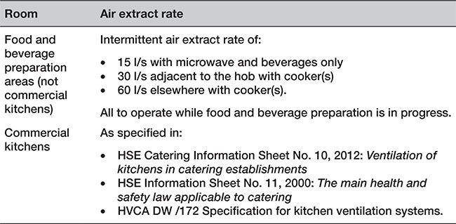
7.20.2.3 Sanitation, hot water safety and water efficiency
• Sanitary conveniences and/or associated hand washing facilities should be separated by a door from any place used for the preparation of food (including a kitchen). |
|
|
G 4.17 |
• Guidance on activity space around sanitary appliances is given in BS 6465-2. |
G 4.18 |
• In all buildings other than dwellings, a sink should be provided in any kitchen or place used for the preparation of food. |
G 6.3 |
• In buildings where the Food Hygiene (England) Regulations 2006 (SI 2006/14) and the Food Hygiene (Wales) Regulations 2006 (SI 2006/31 W5) apply, separate hand-washing facilities may be required. |
|
• This requirement is in addition to hand-washing facilities associated with WCs. |
G 6.4 |
p.1203
7.21.1 Requirements
This section provides the details for buildings other than dwellings only where they differ from the requirements already given in Chapter 6.21.

![]() Note:
Note:
1. Approved Documents B Volume 2 (Fire safety), and M2 (Access to and use of buildings) apply specifically to buildings other than Dwellings.
2. Approved Document Q (Security) does not apply to buildings other than dwellings.
p.1204
7.21.2 Meeting the requirement
7.21.2.1 Fire safety
When an existing house or other building is converted into flats, there is a material change of use and the following apply.
• If the existing building has timber floors and these are to be retained, it may be difficult to meet the provisions for fire resistance. |
B2 7.9 |
• In a building of no more than three storeys, provided that the means of escape conforms to the Approved Document and is adequately protected, it may be possible for elements of structure to have only 30 minutes of fire resistance. |
|
• Where there are four or more storeys, the full standard of fire resistance is required. |
B2 7.10 |
p.1205
7.21.2.2 Access to and use of buildings
• Wheelchair platform stairlifts are only intended for wheelchair users. |
|
• Wheelchair platform stairlifts should only be considered for conversions and alterations where it is not practicable to install a conventional passenger lift or a lifting platform. |
|
• Wheelchair platform stairlifts should not be installed where their operation restricts the safe use of the stair by other people. |
M2 3.44 |
p.1206
7.22 Extensions and additions to buildings
7.22.1 Requirements
This section provides the details for buildings other than dwellings only where they differ from the requirements already given in Chapter 6.22.


![]() Approved Document R (Physical infrastructure for high-speed electronic communications networks) does not apply to conservatories and other small detached buildings.
Approved Document R (Physical infrastructure for high-speed electronic communications networks) does not apply to conservatories and other small detached buildings.
![]() Note:
Note:
1. Approved Document Q (Security) does not apply to buildings other than dwellings.
2. Approved Documents L2A, L2B (Conservation of fuel and power) and M2 (Access to and use of buildings) apply specifically to buildings other than dwellings.
p.1207
7.22.2 Meeting the requirement
7.22.2.1 Resistance to contaminants
Radon is a naturally occurring radioactive colourless and odourless gas formed in small quantities by radioactive decay wherever uranium and radium are found.
• All new buildings, extensions and conversions, whether residential or non-domestic, built in areas where there may be elevated radon emissions, may need to incorporate precautions against radon. More information is available in: |
|
|
|
|
|
|
|
• The Health and Safety Executive provides guidance on protection from radon in the workplace (www.rcr.ac.uk/sites/default/files/bfcr152_irmer.pdf). |
C 2.39 |
• Reports for large workplaces are available from Public Health England (formerly the Health Protection Agency) available at [email protected].uk. |
C 2.40 |
p.1208
7.22.2.2 Ventilation
• The following buildings are exempt from the Ventilation requirements in Approved Document F: |
|
|
|
|
|
|
|
|
|
|
|
• detached buildings of less than 15m2 floor area which do not contain sleeping accommodation |
|
• extensions at ground level with a floor area less than 30m2 (e.g. a conservatory, porch, covered yard, covered way or carport open on at least two sides). |
F 3.3 |
p.1209
7.22.2.3 Conservation of fuel and power
7.22.2.3.1 Historic buildings
• New extensions to historic or traditional buildings should comply with the Approved Documents in relation to standards of energy efficiency. |
|
• Where there is a particular need to match the external appearance or character of the extension to that of the host building the requirements may be relaxed. |
L2B 3.11 |
p.1210
7.22.2.3.2 Consequential improvement
• In buildings with a total useful floor area greater than 1000m2, the construction of an extension will trigger a requirement for consequential improvement. |
L2B 4.1 |
• Where the proposed extension has a total useful floor area that is both greater than 100m2 and greater than 25 percent of the total useful floor area of the existing building, the work should be regarded as a new building. |
L2B 4.2 |
• The proposed extension should incorporate doors, windows, roof windows, rooflights and smoke vents that meet the standards set out in the Approved Document. |
|
• Newly constructed thermal elements should meet the standards set out Table 7.22.1. |
|
• Existing opaque fabric which becomes a thermal element where previously it was not should be upgraded so that it meets the standards in Table 7.22.2. |
L2B 4.3 |
Table 7.22.1 Standards for new thermal elements in dwellings

Table 7.22.2 Upgrading retained thermal elements in dwellings
• The area of windows and rooflights in the extension should generally not exceed the values given in Table 7.22.3. |
|
• Where a greater proportion of glazing is present in the part of the building to which the extension is attached, the proportion of glazing in the extension should be no greater than the proportion that exists in the part of the building to which it is attached. |
|
• Where fixed building services are provided, or extended as part of constructing the extension, reasonable provision would be to follow the guidance in the Approved Documents. |
L2B 4.4 |
p.1211
Table 7.22.3 Opening areas in the extensions to buildings other than dwellings

![]() Authors’ note: There are more flexible approaches than those detailed above. Guidance for these is provided in in paragraphs 4.29 to 4.48 of Approved Document L2B.
Authors’ note: There are more flexible approaches than those detailed above. Guidance for these is provided in in paragraphs 4.29 to 4.48 of Approved Document L2B.
• Where design flexibility is required, it is possible to use an approved calculation tool to demonstrate that the calculated CO2 emissions from the building and proposed extension are no greater than for the building plus a notional extension. |
L2B 4.9 |
• The specification of the existing building used in conjunction with the notional extension as the basis of setting the CO2 target for the building work should include all upgrades that are being undertaken to fulfil the requirement for consequential improvements. |
L2B 4.10 |
• Where additional upgrades over and above the consequential improvements are proposed in the actual building to compensate for lower performance in the extension, such upgrades should be implemented to a standard that is no worse than that specified in Approved Document L2B. |
|
• The standards for upgrades that are set out in Approved Document L2B are considered to be cost effective and should be implemented in full. |
L2B 4.11 |
• Removing, and not replacing, any of the thermal separation between the building and an existing exempt extension, or extending the building’s heating system into the extension, means that the extension ceases to be exempt. In such situations, the extension should be treated as a conventional extension. |
L2B 4.13 |
• In addition to the proposed building work, consequential improvements should be made to ensure that the building complies with the Approved Documents; as long as they are technically, functionally and economically feasible. |
L2B 6.3 |
• The U-value of the floor of an extension can be calculated using the exposed perimeter and floor area of the whole enlarged building. |
L2B Table 5 |
![]() If all the roofing on the flat roof of an extension is being stripped down, the area of the individual element is the ‘roof area’ of the extension, not the ‘total roof area’ of the building. Similarly, if the rear wall of a single-storey extension is being re-rendered externally, then the rear wall of the extension should be upgraded even if the renovation affected less than 50 percent of the total area of the building elevation when viewed from the rear. If plaster is being removed from a bedroom wall, the relevant area is the area of the external wall in the room, not the area of the external elevation which contains that wall section. This is because the cost of drylining with insulated plasterboard rather than plain plasterboard is small.
If all the roofing on the flat roof of an extension is being stripped down, the area of the individual element is the ‘roof area’ of the extension, not the ‘total roof area’ of the building. Similarly, if the rear wall of a single-storey extension is being re-rendered externally, then the rear wall of the extension should be upgraded even if the renovation affected less than 50 percent of the total area of the building elevation when viewed from the rear. If plaster is being removed from a bedroom wall, the relevant area is the area of the external wall in the room, not the area of the external elevation which contains that wall section. This is because the cost of drylining with insulated plasterboard rather than plain plasterboard is small.
p.1212
7.22.2.3.3 New freestanding buildings
• New buildings include any new free-standing building on an existing site (e.g. a new outpatients building at an existing hospital site or a new classroom block at a school). These are not classified as an extension. |
L2B 6.6 |
p.1213
7.22.2.3.4 Doors
• If a door is enlarged or a new one created in a building other than a dwelling, the area of the pedestrian door, expressed as a percentage of the total floor area of the building, should not exceed the relevant value from Table 7.22.4. |
L2B 4.24 |
p.1214
Table 7.22.4 Opening areas in the extension

p.1215
7.22.2.3.5 Pressure testing
• All buildings that are not dwellings (including extensions which are being treated as new buildings) must be subject to pressure testing, with the following exception: |
|
|
|
|
L2A 3.12a |
• In large extensions where it is impractical to seal off the extension then the extension should be treated as a large, complex building provided that the BCB agrees. |
L2A 3.12c |
p.1216
7.22.2.4 Access to and use of buildings
For buildings other than dwellings, the Approved Documents require the provision of suitable accessible entrances for all users.
• An extension to a non-domestic building should be treated as a new building. |
M2 0.5 |
• If sanitary conveniences are already provided in the building, provision should also be made in an extension for sanitary conveniences. |
|
• If there is provision for people using the extension to access and use sanitary conveniences in the existing building, there is no requirement for sanitary conveniences in the extension. |
M2 0.8 |
• The principal entrance, any main staff entrance, and any lobby should be accessible. |
|
• Where this is not possible, an alternative accessible entrance should be provided. |
M2 0.5 M2 2.2 |
• Corridors and passageways should be wide enough to allow people with buggies, people carrying cases or people on crutches to pass others on the access route. |
|
|
|
|
|
|
|
• Corridors which are narrower than indicated in this guidance, or that narrow in one location (e.g. at archways), might be permitted in existing buildings or in some extensions. |
M2 3.11 |
p.1217
7.23.1 Requirements
This section provides the details for buildings other than dwellings only where they differ from the requirements already given in Chapter 6.23.

p.1218
![]() Approved Document R (Physical infrastructure for high-speed electronic communications networks) does not apply to conservatories and other small detached buildings.
Approved Document R (Physical infrastructure for high-speed electronic communications networks) does not apply to conservatories and other small detached buildings.
![]() Note:
Note:
1. Approved Document M Volume 2 (Access to and use of buildings) applies specifically to buildings other than dwellings.
2. Approved Document Q (Security) does not apply to buildings other than dwellings.
p.1219
7.23.2 Meeting the requirement
7.23.2.1 Access to and use of buildings
For buildings other than dwellings the Approved Documents require you to provide suitable accessible entrances for all users.
