
p.235
6_______________________
Meeting the requirements of the Building Regulations – Dwellings
6.0.1 How to use this chapter
This chapter has been designed to help you meet the requirements of the Building Regulations in dwelling houses, flats and rooms for residential purposes (hereafter referred to as dwellings). We have adopted a foundations-up approach, as shown in Figures 6.0.1 and 6.0.2, by putting all the relevant Approved Document requirements that relate to each specific area (e.g. windows) into each section.
p.236
![]() Authors’ note: In Chapter 7, we describe the requirements for ‘Buildings other than dwellings’ but, as a high percentage of the requirements, information and explanations about Building Regulations in dwellings is also applicable to buildings other than dwellings, Chapter 7 will only include information specific to non-dwellings.
Authors’ note: In Chapter 7, we describe the requirements for ‘Buildings other than dwellings’ but, as a high percentage of the requirements, information and explanations about Building Regulations in dwellings is also applicable to buildings other than dwellings, Chapter 7 will only include information specific to non-dwellings.
However, to assist the reader, we use the same sub-chapter heading in both chapters (for example, 6.1 and 7.1 are both entitled ‘Foundations’). The reader using Chapter 7 will need to refer back to Chapter 6 to see if there are any general purpose requirements or information that should be taken account of.
Each section of Chapter 6 is structured to discuss the precise requirement and then how to meet the requirement. Sections start with a table which shows which part of each Approved Document applies to a particular aspect of the building. For example, in the case of foundations, this would be:
p.237

Figure 6.0.1 Diagrammatic representation of the contents of Chapter 6

Figure 6.0.2 Diagrammatic representation of the contents of Chapter 6 – elements
p.238
6.1.1 Requirements
Table 6.1.1 Requirements of the Building Regulations: Foundations

p.239
Very often, a number of Approved Documents will apply; therefore, each section follows the alphanumeric order of the Approved Document. Where a specific Approved Document does not apply, it is omitted from the section.
In the case of the example above this would be:
p.240
6.1.2 Meeting the requirement
6.1.2.1 Structure
6.1.2.1.1 Structural safety
and so on
![]() Note: Cross-sectional diagrams, tables and further amplification are also provided where necessary.
Note: Cross-sectional diagrams, tables and further amplification are also provided where necessary.
We follow the same numbering order in each section and also number figures and tables by section so that you can easily find what you are looking for.
p.241
![]() For your assistance (and to avoid you having to constantly refer back), where tables and figures are common for a number of sections we have deliberately duplicated them in each section.
For your assistance (and to avoid you having to constantly refer back), where tables and figures are common for a number of sections we have deliberately duplicated them in each section.
Chapters 6 and 7 are further supported by appendices, which cover specific areas in greater detail (as entities in their own right rather than how they apply to a particular project) and these are available on the publisher’s website at www.routledge.com/9781138285163.
p.242
Appendix A Entrance and access
Appendix B Conservation of fuel and power
p.243
Appendix C Fire resistance and escape
Appendix D Electrical safety (dwellings)
Owing to the huge amount of information contained in the Approved Document series, and in an effort to help you ‘sort the wood from the trees’, the following symbols have been used to help you.

p.244

6.0.2 Background
The Building Regulations provide a practical guide to meeting the requirements of Schedule 1 and Regulation 7 of the Building Regulations and the latest edition of the Building Regulations and the Building (Approved Inspectors etc.) Regulations.
Since the issue of the Building Regulations 2010, two new Approved Documents have been added (namely Q and R) and Approved Document M has been substantially revised. Approved Document N was removed and its contents added to Approved Document K and M. There have been consequential revisions to other Approved Documents as a result of these changes.
6.0.3 Approved Documents
The documents listed in Table 6.0.1 are derived for the latest amendments of the Approved Documents at time of writing.
p.245
Table 6.0.1 List of Approved Documents

![]() Note: The changes to Approved Documents apply initially in England until the devolved governments adopt them for their own publications.
Note: The changes to Approved Documents apply initially in England until the devolved governments adopt them for their own publications.
Electronic copies of Approved Documents may be downloaded from the following sources:
• England: www.planningportal.gov.uk/buildingregulations/approveddocuments
• Wales: www.gov.wales/topics/planning/buildingregs/approved-documents
• Northern Ireland: www.buildingcontrol-ni.com/regulations/technical-booklets
p.246
• Scotland: www.gov.scot/Topics/Built-Environment/Building/Building-standards/techbooks/techhandbooks.
Bound copies may be obtained from TSO (see www.tso.co.uk) or RIBA (www.architecture.com).
6.0.4 Compliance
There is no binding obligation to adopt any particular solution that is contained in an Approved Document. However, as the Approved Documents contain both the guidance on how to comply with the Regulation as well as extracts from the Regulations, you should be careful to ensure that you comply with the regulatory text! However, should a contravention of a requirement be alleged, if you have followed the guidance in the relevant Approved Documents, that will be regarded as evidence suggesting that you have complied with the Regulations. If you have not followed the guidance, that will be viewed as evidence suggesting that you have not complied with the requirements, and it will then be up to you, as the builder, architect and/or client, to demonstrate how you have satisfied the requirements of the Building Regulations.
p.247
6.0.4.1 Building Control Body compliance
Fixed building services, including controls, should be commissioned by testing and adjusting as necessary to ensure that they use no more fuel and power than is reasonable in the circumstances.
If you are intending to carry out building work, it is best to always check with your Building Control Body (BCB) or one of your Local Authorities’ Approved Inspectors first to ensure that your or their proposals comply with Building Regulations!
6.0.5 Responsibility for compliance with Approved Documents
It is important to remember that, if you are the person (e.g. designer, builder, installer) carrying out building work to which any requirement of Building Regulations applies, you are directly responsible for ensuring that the work complies with any such requirement.
The building owner also has a responsibility for ensuring compliance with Building Regulation requirements, and could be served with an enforcement notice in cases of non-compliance!
p.248
6.0.6 Materials and workmanship
Any building work which is subject to the requirements imposed by Schedule 1 to the Building Regulations shall be carried out in accordance with Regulation 7.

Building Regulations are made for specific purposes (primarily the health and safety, welfare and convenience of people and for energy conservation) and these are supported by guidance standards and other technical specifications relevant to these Regulations. The supporting documents may also address other aspects of performance or matters which, although they relate to health and safety, are not directly covered by the Building Regulations. In accordance with Regulation 8 of the Building Regulations, the requirements in Approved Documents (except for G2, H2 and J7) do not require anything specific to be done except those things which are needed to secure reasonable standards of health and safety for persons in or about buildings (and any others who may be affected by buildings or matters connected with buildings).
• Section G2 is excluded because it deals with water efficiency, and Sections H2 and J7 are excluded from Regulation 8 because they deal directly with the prevention of the contamination of water.
p.249
• Approved Documents E and M (which deal, respectively, with resistance to the passage of sound, and access to and use of buildings) are excluded from Regulation 8 because they address the welfare and convenience of building users.
• Approved Document L is excluded from Regulation 8 because it addresses the conservation of fuel and power.
6.0.7 What materials can I use?
Other than for short-lived and unusable materials (see below), you may show that you have complied with Regulation 7 in a number of ways, such as by using:
p.250
• a product bearing CE marking in accordance with the Construction Products Directive (305/2011/EU-CPR, The Gas Appliances Directive (2009/142/EC) or the Pressure Equipment Directive (97/23/EC)
• a product complying with an appropriate technical specification, such as:
![]() a British Standard which is a national version of a harmonized European standard
a British Standard which is a national version of a harmonized European standard
![]() an alternative ISO or national technical specification of a country other than the UK that meets the requirements of the Building Regulations
an alternative ISO or national technical specification of a country other than the UK that meets the requirements of the Building Regulations
![]() a product covered by a national or European certificate issued by a European Technical Approval issuing body, provided the conditions of use are in accordance with the terms of the certificate.
a product covered by a national or European certificate issued by a European Technical Approval issuing body, provided the conditions of use are in accordance with the terms of the certificate.
![]() Note: Where there is no relevant harmonized European standard, then tests, calculations or other means may be used to demonstrate that the material can perform the function for which it is intended.
Note: Where there is no relevant harmonized European standard, then tests, calculations or other means may be used to demonstrate that the material can perform the function for which it is intended.
![]() Authors’ note: Following Brexit there is likely to be much change in this area as the British Standards decouple from the European regulations. At the time of writing there was no guidance on the likely scale of such changes.
Authors’ note: Following Brexit there is likely to be much change in this area as the British Standards decouple from the European regulations. At the time of writing there was no guidance on the likely scale of such changes.
p.251
6.0.8 Short-lived materials
Even if a plan for building work complies with the Building Regulations, if this work has been completed using short-lived materials (i.e. materials which, in the absence of special care, are liable to rapidly deteriorate in relation to the expected life of the building) the Local Authority can:
• reject the plans
• pass the plans subject to a limited use clause (on expiration of which they will have to be removed)
• restrict the use of the building.
(Building Act 1984, Section 19)
p.252
6.0.9 Unsuitable materials
If, once building work has begun, it is discovered that it has been made using materials or components that have been identified by the Secretary of State (or a nominated deputy) as being ‘unsuitable materials’, the Local Authority has the power to:
p.253
• reject the plans
• fix a period within which the offending work must be removed
• restrict the use of the building.
(Building Act 1984, Section 20)
![]() If the person completing the building work fails to remove the unsuitable material or component(s), then that person is liable to be prosecuted and, on summary conviction, faces a heavy fine.
If the person completing the building work fails to remove the unsuitable material or component(s), then that person is liable to be prosecuted and, on summary conviction, faces a heavy fine.
p.254
6.0.10 Technical specifications
Building Regulations may be made for specific purposes such as:
• health and safety
• welfare and convenience of disabled people
• conservation of fuel and power
• prevention of waste or contamination of water.
p.255
![]() Note: These are aimed at furthering the protection of the environment, facilitating sustainable development, or the prevention and detection of crime.
Note: These are aimed at furthering the protection of the environment, facilitating sustainable development, or the prevention and detection of crime.
Although the main requirements for health and safety are now covered by the Building Regulations, there are still some requirements contained in the Workplace (Health, Safety and Welfare) Regulations 1992 that may need to be considered, as they could contain requirements which affect building design. For further information see Workplace (Health, Safety and Welfare) Regulations 1992. Approved Code of Practice L24 (Second Edition, 2013).
p.256
Standards and technical approvals, as well as providing guidance, also address other aspects of performance, such as serviceability and/or other characteristics related to health and safety not covered by the Building Regulations.
When an Approved Document makes reference to a named standard, the relevant version of the standard is the one listed at the end of that particular Approved Document. However, if this version of the standard has been revised or updated by the issuing standards body, the new version may be used as a source of guidance, provided that it continues to address the relevant requirements of the Building Regulations.
The Secretary of State has agreed (with the British Board of Agrément) on aspects of performance that they need to assess in preparing their Agrément Certificates so that the Board can demonstrate compliance of a product or system with the requirements of the Building Regulations. An Agrément Certificate issued by the Board under these arrangements will give assurance that the product or system to which the certificate relates (if properly used in accordance with the terms of the certificate) will meet the relevant requirements.
p.257
6.0.11 Independent certification schemes
Within the UK, there are many product certification schemes that certify compliance with the requirements of a recognized standard or document that is suitable for the purpose and material being used. Certification bodies that approve such schemes will normally be accredited by the United Kingdom Accreditation Service (UCAS).
Competent person self-certification schemes that register installers of materials may also be used as a means of ensuring that the work is carried out by a competent contractor and to the appropriate standard.
6.0.12 Standards and technical approvals
Standards and technical approvals provide guidance related to the Building Regulations and address other aspects of performance, such as serviceability, or aspects which, although they relate to health and safety, are not covered by the Regulations.
p.258
6.0.13 House – construction
There are two main types of building in common use today: those made of brick and those made of timber. There are many different styles of brick-built houses and, equally, there are various methods of construction.
Brickwork, as well as giving a building character, provides the main load-bearing element of a brick-built house. (See Figure 6.0.3).
Timber-framed houses, on the other hand, are usually built on a concrete foundation with a ‘strip’ or ‘raft’ construction to spread the weight, and differ from their brick-built counterparts in that the main structural elements are timber frames. (See Figure 6.0.4.)

Figure 6.0.3 Brick-built house – typical components
p.259
6.0.14 Buildings – size
6.0.14 1 Classification of purpose groups
Many of the provisions in the Approved Documents are related to the use of the building. The classifications ‘use’ purpose groups and represent different levels of hazard. They can apply to a whole building, or (where a building is compartmented) to a particular compartment (e.g. a kitchen) in the building and the relevant purpose group should be taken from the main use of the building or compartment. Table 6.8 sets out the purpose group classification.

Figure 6.0.4 Timber-framed house – typical components
p.260
Table 6.0.2 Classification of purpose groups

p.261
6.0.14.2 Requirements – size of residential buildings

p.262

Figure 6.0.5 Residential buildings not more than three storeys
p.263

Figure 6.0.6 Size and proportion of non-residential annexes
p.264
6.0.14.3 Size of annexes
![]()
p.265
6.0.15 The use of Robust Details
One of the recommendations of Approved Document E (Resistance to the passage of sound) involves pre-completion sound testing (PCT) for certain types of home. This is an attempt to eliminate the risk of any remedial work being required to completed floor and/or wall constructions (together with the potential for delays in completing the property). Since 2004, Robust Details Ltd is responsible for approving, managing and promoting the use of Robust Details as a method of satisfying Building Regulations.
6.0.15.1 What is a Robust Detail?
Robust Details are high performance separating wall and floor constructions (with associated construction details) that are expected to be sufficiently reliable to not need the check provided by pre-completion testing. The Robust Details Scheme is an alternative to pre-completion sound testing (PCT) of separating walls and floors in new-build joined houses, bungalows and flats, to demonstrate compliance with the relevant minimum Building Regulation performance standards in England, Wales, Scotland and Northern Ireland.
p.266
Robust Details provide builders with a choice of possible construction solutions that have been proven to outperform the standards of Approved Document E, thus eliminating the need for routine PCT. A Robust Detail is only used in connection with Approved Document E and is defined as a separating wall or floor (of concrete, masonry, timber, steel or steel-concrete composite) construction, which has been assessed and approved by Robust Details Ltd.
6.0.15.2 How are Robust Details approved?
In order to be approved, each Robust Detail must be:
• capable of consistently exceeding the performance standards given in Approved Document E to the Building Regulations
• practical to construct on site
• reasonably tolerant to workmanship.
p.267
6.0.15.3 How can Robust Details be used?
Builders are only permitted to use Robust Details instead of PCT if the plots concerned have been registered in advance with Robust Details Ltd. Once a plot has been registered, Robust Details Ltd will provide the relevant registration documentation, which will be accepted by all Building Control Bodies as evidence that the builder is entitled to use Robust Details instead of PCT. The builder will then need to select the Robust Detail specific to the walls and/or floors they wish to build from the Robust Details handbook (available from Robust Details Ltd) and produce a site work checklist to show how they will ensure that building work is carried out exactly in accordance with the Robust Detail specifications.
p.268
6.0.15.4 Will there be more Robust Details?
Trade associations, manufacturers or other interested parties may submit applications for new Robust Details, and these will be evaluated and, if found acceptable, approved and published.
6.0.15.5 Where can I obtain more information?
More information is available from Robust Details Ltd (www.robustdetails.com) and full contact information is in the ‘Useful contact names and addresses’ section at the end of this book.
p.269
6.0.16 Site preparation and resistance to contaminants and moisture
Some contaminants can penetrate the floors of buildings, such as landfill gas arising from the deposition of waste and vapours from spills of organic solvents and fuel. These contaminants can also migrate laterally from land outside the building. In order to deal with this, Approved Document C (Site preparation and resistance to contaminates and moisture) now applies to all changes of use that have a residential purpose or provide sleeping accommodation.
The rate at which gas seeps into buildings, mainly through floors, can be reduced by edge-located sumps or subfloor vents. These are less intrusive than internal sumps or ducts that may involve taking up floors. If flagged floors are taken up, the stones should be indexed and their layout recorded to facilitate relaying when work is completed.
Approved Document C gives guidance for the following situations:
• ground-supported floors exposed to moisture from the ground
• suspended-timber ground floors exposed to moisture from the ground
• suspended-concrete ground floors exposed to moisture from the ground
p.270

Figure 6.0.7 Typical concrete floor
p.271
• the risk of interstitial condensation in ground floors and floors exposed from below
• the risk of surface condensation and mould growth on any type of floor.
![]() A floor is an element of structure and should be treated as such.
A floor is an element of structure and should be treated as such.
For the purposes of this section, a floor is considered to be the lower horizontal surface of any space in a building and includes finishes that are laid as part of the permanent construction. The ground floor of a building may be made of solid concrete or suspended timber type. With a concrete floor, a damp-proof membrane is laid between walls.
With timber floors, sleeper walls of honeycomb brickwork are built on oversite concrete between the base brickwork; a timber sleeper plate rests on each wall, and timber joists are supported on them. Their ends may be similarly supported, let into the brickwork or suspended on metal hangers. Floorboards are laid at right angles to joists. First-floor joists are supported by the masonry or hangers.
As with brick-built house, the floors in a timber-framed house may be solid concrete or suspended timber. In some cases, a concrete floor may be screeded or surfaced with timber or chipboard flooring. Suspended-timber floor joists are supported on wall plates and surfaced with chipboard. Guidance on the sizing of timber floors and roofs for traditional house construction known as the Timber Tables are published by TRADA.
p.272
6.1 Foundations
To support the weight of the structure, most brick-built buildings are supported on a solid concrete base which is called the ‘foundation’. Timber-framed houses are usually built on a concrete foundation with a ‘strip’ or ‘raft’ construction to spread the weight. Maintenance on foundations generally does not require planning permission. However, if you live in a listed building or designated area (conservation area, national park or Area of Outstanding Natural Beauty) you should check with your Local Planning Authority before carrying out any work.
![]() The Local Authority is entitled to carry out tests of the soil or subsoil of the site of the building and you can be prosecuted or ordered to carry out remedial work on a property, whether you are the owner or merely the occupier.
The Local Authority is entitled to carry out tests of the soil or subsoil of the site of the building and you can be prosecuted or ordered to carry out remedial work on a property, whether you are the owner or merely the occupier.
Underpinning is a construction method which increases the depth of the foundations of a building by excavating the existing foundations and replacing them with new foundation material. The reasons for underpinning are:
• movement of the existing foundations (e.g. caused by poor soil or changes to the soil conditions through subsidence etc.)
• adding another storey to the building where the depth of the existing foundations is inadequate to support the modified building’s weight.
Underpinning work will require very careful planning and execution and (if you propose to underpin an existing foundation) Building Regulations approval will normally be required. In order that you do not undermine the existing foundations, causing further damage to the structure above and raising the possibility of the building collapsing, any excavations for underpinning should be carried out under the instructions of a suitably qualified engineer.
![]() Note: Filling the excavation with concrete will not necessarily guarantee that the underpinning will provide sufficient support to the existing foundations, because of the possibility that cavities will remain between the two. It is, therefore, recommended, and usually necessary, for a sand and cement packing to be rammed into the void in stages, to ensure adequate support. The timing of each stage and the specification of the materials to be used will vary on a case-by-case basis and should normally be the subject of a structural engineer’s design.
Note: Filling the excavation with concrete will not necessarily guarantee that the underpinning will provide sufficient support to the existing foundations, because of the possibility that cavities will remain between the two. It is, therefore, recommended, and usually necessary, for a sand and cement packing to be rammed into the void in stages, to ensure adequate support. The timing of each stage and the specification of the materials to be used will vary on a case-by-case basis and should normally be the subject of a structural engineer’s design.
p.273
6.1.1 Requirements

![]() Note: For the purpose of this requirement, ‘contaminant’ means any substance which is, or may, become harmful to persons or buildings, including substances that are corrosive, explosive, flammable, radioactive or toxic.
Note: For the purpose of this requirement, ‘contaminant’ means any substance which is, or may, become harmful to persons or buildings, including substances that are corrosive, explosive, flammable, radioactive or toxic.
p.274
6.1.2 Meeting the requirements
6.1.2.1 Structure
6.1.2.1.1 Structural safety

6.1.2.1.2 Ground movement

![]() Note: The reports from these reviews, which include 1:250,000 scale maps showing the distribution of the physical constraints, are available from a number of licence holders, including the British Geological Survey.
Note: The reports from these reviews, which include 1:250,000 scale maps showing the distribution of the physical constraints, are available from a number of licence holders, including the British Geological Survey.
6.1.2.1.3 Basic requirements for stability

p.275

![]() Note: A traditional cut-timber roof (such as one using rafters, purlins and ceiling joists) generally has sufficient built-in resistance to instability and wind forces (e.g. from hipped ends, tiling battens and rigid sarking). However, the need for diagonal rafter bracing equivalent to that recommended in BS EN 1995–1-1 should be considered, especially for single-hipped and non-hipped roofs of greater than 40° pitch to detached houses.
Note: A traditional cut-timber roof (such as one using rafters, purlins and ceiling joists) generally has sufficient built-in resistance to instability and wind forces (e.g. from hipped ends, tiling battens and rigid sarking). However, the need for diagonal rafter bracing equivalent to that recommended in BS EN 1995–1-1 should be considered, especially for single-hipped and non-hipped roofs of greater than 40° pitch to detached houses.
6.1.2.1.4 Residential buildings not more than three stories and their annexes

p.276

Figure 6.1.1 Residential buildings not more than three storeys
p.277


Figure 6.1.2 Map showing wind speeds in m/s for maximum height of buildings
6.1.2.1.4.1 annexes
![]()

Figure 6.1.3 Proportion and size of annexes
6.1.2.1.5 Maximum floor area

p.278

Figure 6.1.4 Maximum floor area that is enclosed by structural walls
Table 6.1.1 Imposed loads

![]()
6.1.2.1.6 Heights of walls and storeys

p.279

Figure 6.1.5 Measuring storey and wall heights
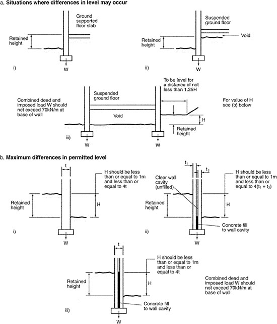
Figure 6.1.6 Differences in ground levels
p.280
6.1.2.1.7 Foundations – plain concrete

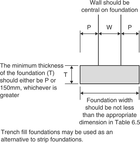
Figure 6.1.7 Foundation dimensions
p.281
Table 6.1.2 Minimum width of strip footings

p.282
![]() Note: This depth will commonly need to be increased in areas subject to long periods of frost or in order to transfer the loading onto satisfactory ground.
Note: This depth will commonly need to be increased in areas subject to long periods of frost or in order to transfer the loading onto satisfactory ground.

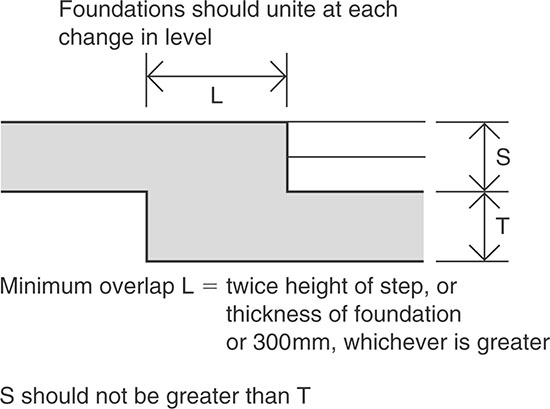
Figure 6.1.8 Elevation of stepped foundation
![]() Note: Steps in foundations should not be of greater height than the thickness of the foundation.
Note: Steps in foundations should not be of greater height than the thickness of the foundation.

p.283
![]() The projection X should never be less than the value of P where there is no local thickening of the wall.
The projection X should never be less than the value of P where there is no local thickening of the wall.

Figure 6.1.9 Piers and chimneys
6.1.2.1.8 Strip foundations

The most common signs that foundations have problems are hairline cracks or fractures in walls, buckling or crumbling walls, evidence of water damage, sagging floors or warped ceilings, and badly fitting doors and windows.
p.284
6.1.2.2 Site preparation and resistance to contaminants and water
6.1.2.2.1 Hazards associated with the ground

![]() Note: The Contaminated Land (England) Regulations 2006 (as amended 2012) empowers Local Authorities to oversee the management of cause and effects of land contamination and this process is subject to controls under the Town and Country Planning Acts, and guidance in the National Planning Policy Framework.
Note: The Contaminated Land (England) Regulations 2006 (as amended 2012) empowers Local Authorities to oversee the management of cause and effects of land contamination and this process is subject to controls under the Town and Country Planning Acts, and guidance in the National Planning Policy Framework.

Construction activities undertaken as part of building development can alter the gas regime on the site (e.g. a site strip can increase surface gas emissions, as can piling and excavation for foundations, and dynamic compaction can push dry biodegradable waste into moist, gas-active zones). General excavation work for foundations and services can also alter groundwater flows through the site. Potential problems include:

6.1.2.2.2 Contaminated ground
Potential building sites which are likely to contain contaminants can be identified at an early stage from planning records or from local knowledge (e.g. previous usage and users). In addition to solid and liquid contaminants, problems can also arise from natural contamination such as methane and the radioactive radon gas (and its decay product). Contaminated land may previously have been used as a factory, mine, steel mill or landfill. Sites which are classed as ‘special sites’ includes land that:
p.285
• seriously affects drinking waters, surface waters or important groundwater sources
• has been, or is being, used for certain industrial activities, such as oil refining or making explosives
• is being, or has been, regulated using a permit issued under the integrated pollution control or pollution prevention and control regimes
• has been used to get rid of waste acid tars
• is, or has been, owned and/or occupied by the Ministry of Defence
• is contaminated by radioactivity
• is a nuclear site.
![]() The Environment Agency produces technical guidance on special sites and these are regulated by the Environment Agency in England, Natural Resources Wales in Wales and the Scottish Environment Protection Agency (SEPA) in Scotland.
The Environment Agency produces technical guidance on special sites and these are regulated by the Environment Agency in England, Natural Resources Wales in Wales and the Scottish Environment Protection Agency (SEPA) in Scotland.
Land is legally defined as ‘contaminated land’ where substances are causing, or could cause, significant harm to people, property or protected species, significant pollution of groundwater or other harm to people as a result of radioactivity. It is the responsibility of the Environment Agency or Local Authority to decide if land is contaminated and how the problem should be dealt with, to ask the responsible person to deal with the contamination and to tell them what to do (e.g. fence it off).
Who is responsible for any contamination and how they should deal with it will depend on whether the land is legally considered ‘contaminated land’. If the land counts as contaminated land the person who is normally responsible for dealing with the contamination is usually the person who caused or allowed the contamination to happen. If this person cannot be identified or the agency investigating the issue decides they are exempt, then that agency will then decide who is responsible for dealing with the problem (this can be the person who uses the land or the landowner).
![]() If the person responsible does not deal with the contamination, the Local Authority or agency will send them a ‘remediation notice’, telling them when they must take care of it by.
If the person responsible does not deal with the contamination, the Local Authority or agency will send them a ‘remediation notice’, telling them when they must take care of it by.
You can agree a voluntary scheme with the Local Authority or agency if you are responsible for part or all of the clean up. You must state what steps you will take to clean up the land. If you are developing the land you will need to deal with the contamination either before you get planning permission or as part of the development.
p.286
![]() Note: Whatever the situation, you are advised to contact your Local Authority to check what you must do to make sure the land is suitable for any proposed development. More advice can be found at www.gov.uk/government/collections/land-contamination-technical-guidance.
Note: Whatever the situation, you are advised to contact your Local Authority to check what you must do to make sure the land is suitable for any proposed development. More advice can be found at www.gov.uk/government/collections/land-contamination-technical-guidance.
A preliminary site assessment is required to provide information on the past and present uses of the site and surrounding area that may give rise to contamination (see Table 6.1.3).
Table 6.1.3 Examples of possible contaminants

The Planning Authority should be informed prior to any intrusive investigations or if any substance is found which was not identified in a preliminary statement about the nature of the site.

p.287
6.1.2.2.3 Gaseous contaminants?
6.1.2.2.3.1 radon
Radon (measured in becquerels per cubic metre of air or Bq m-3) is a colourless, odourless, naturally occurring radioactive gas formed by decaying uranium that occurs naturally in all rocks and soils. Normally the gas that escapes from rock or soil is immediately diluted by the atmosphere and thus poses no harm to humans. However, when radon is trapped in an enclosed space, it can seep out of the ground and build up in houses, other buildings, and indoor workplaces, and studies have established that exposure to radon is the second largest cause of lung cancer in the UK after smoking. Some parts of the country (in particular, England’s West Country) have higher natural levels than elsewhere, and precautions against radon may be necessary.
Essentially a house acts as a chimney. Air rises through the house as it warms and also due to the suction effects on the roof caused by wind action. The warm air eventually finds its way out via gaps at the top of the house. This air is then replaced by more air entering lower down in the house. The highest levels of radon are generally found in the early hours of the morning and in the middle of winter – in other words, the coldest times, when buildings are tightly closed.
p.288
The average level in UK homes is 20 Bq m-3 and, for levels below 100 Bq m3, individual risk remains relatively low and not a cause for concern; however, the risk increases as the radon level increases.
p.289

Figure 6.1.10 Common entry points of radon gas and household airflow

Figure 6.1.11 Average annual dose of radon to UK population
Guidance on whether an area is susceptible to radon (and appropriate protective measures) can be obtained from BRE Report BR 211 Radon: Protective measures for new buildings (2015). The report applies to all new buildings, extensions, conversions and refurbishment for domestic or non-domestic use (unless subject to local exemptions contained within the above Regulations. The UK Radon Association has an online interactive map showing areas at risk.
An alternative approach to using these maps would be to obtain a radon risk report. The following services are available:
• A radon risk report can be obtained for any small home or workplace under 25m in length. There is a charge for this service (£3.90 at the time of writing) but the report is instantly available to save and complies with the standard legal enquiries on house purchase.
• A Radon home measurement pack costs £49.80 (at the time of writing) and includes two detectors and placement instructions. The homeowner places the detectors in accordance with instructions and returns them to Public Health England after three months for analysis.
These services are available from:
• UK Radon (www.UKradon.org), for small domestic and workplace buildings (and extensions) that have an existing postal address
• British Geographical Survey Georeports (shop.bgs.ac.uk/georeports) for other development sites.
![]() The radon risk reports will provide a more accurate assessment of whether radon protective measures are necessary and, if needed, the level of protection that is appropriate.
The radon risk reports will provide a more accurate assessment of whether radon protective measures are necessary and, if needed, the level of protection that is appropriate.

The estimated costs for protecting dwellings against radon is not prohibitive and should be considered. Some work can be completed by the average DIY enthusiast while other work requires more specialist intervention. The UK Radon Association estimates that costs are likely to run from £800–£2000 but more details can be found at www.radonassociation.co.uk/guide-to-radon/information-for-house-buyers-and-seller and in the table below.
Table 6.1.4 Estimated costs of radon protective measures


Figure 6.1.12 Protective measures for concrete floors
6.1.2.2.3.2 landfill gas
Landfill gas is generated by the action of anaerobic micro-organisms on biodegradable material in landfill sites, and generally consists of methane and carbon dioxide together with small quantities of VOCs (volatile organic compounds), which give the gas its characteristic odour. Landfill gas can migrate under pressure through the subsoil and through cracks and fissures into buildings.
p.290
Methane and carbon dioxide can also be produced by organically rich soils and sediments such as peat and river silts, and a wide range of VOCs can be present as a result of petrol, oil and solvent spillages.

![]() All will require careful analysis.
All will require careful analysis.
6.1.2.2.4 Site investigation
Site investigation is now the recommended method for determining how much unsuitable material should be removed before commencing building work. This investigation will normally consist of well-defined stages, for example those shown in Table 6.1.5.
Table 6.1.5 Site investigation stages

6.1.2.2.5 Risk assessment
The site investigation may identify certain risks, which will require a risk assessment. There are three types of risk assessment:
• preliminary (once the need for a risk assessment has been identified, and depending on the situation and the outcome)
• Generic Quantitative Risk Assessment (GQRA)
• Detailed Quantitative Risk Assessment (DQRA).
Table 6.1.6 shows what each risk assessment should include.
p.291
Where the site is potentially affected by contaminants, a combined geotechnical and geo-environmental investigation should be considered.
Table 6.1.6 Risk assessments

6.1.2.2.6 Flood resistance
Although flood resistance is not currently a requirement of the Building Regulations, as part of its aim to improve the energy efficiency of buildings and use planning to protect the environment, the policies set out in the revised 2012 National Planning Policy Framework suggest that Local Planning Authorities should adopt proactive strategies to mitigate and adapt to climate change, taking full account of flood risk, coastal change and water supply demand considerations (see www.gov.uk/guidance/national-planning-policy-framework/10-meeting-the-challenge-of-climate-change-flooding-and-coastal-change).
p.292
6.1.2.2.7 Gaseous risk assessment

p.293

A risk assessment based on the concept of a ‘source–pathway–receptor’ relationship, or pollutant linkage of a potential site (see Figure 6.1.13) should be carried out to ensure the safe development of land that is affected by contaminants.

Figure 6.1.13 Conceptual model of a site showing a source–pathway–receptor relationship
p.294
6.1.2.2.8 Ground investigation

![]() Note: During the development of land affected by contaminants, the health and safety of both the public and workers should be considered.
Note: During the development of land affected by contaminants, the health and safety of both the public and workers should be considered.
6.1.2.2.9 Remedial measures

6.1.2.2.10 Corrective measures

Depending on the contaminant, three generic types of corrective measure can be considered: treatment, containment and/or removal.
![]() Note: The containment or treatment of waste may require a waste management licence from the Environment Agency.
Note: The containment or treatment of waste may require a waste management licence from the Environment Agency.
p.295
6.1.2.2.11 Treatment
The choice of the most appropriate treatment process is a highly site-specific decision for which specialist advice should be sought.
6.1.2.2.12 Containment
6.1.2.2.13 Removal

6.1.2.2.14 Site preparation

![]() Where mature trees are present (particularly on sites with shrinkable clays; see Table 6.1.7) the potential damage arising from ground heave to services and floor slabs and oversite concrete should be assessed.
Where mature trees are present (particularly on sites with shrinkable clays; see Table 6.1.7) the potential damage arising from ground heave to services and floor slabs and oversite concrete should be assessed.
Table 6.1.7 Volume change potential for some common clays

6.1.2.2.15 Foundations and types of soil
Table 6.1.8 provides guidance on determining the type of soil on which it is intended to lay a foundation.
Table 6.1.8 Types of subsoil

6.1.2.2.16 Subsoil drainage

p.296


Figure 6.1.14 Subsoil cut during excavation
6.1.2.2.17 Building size
Many of the provisions in the Approved Document C (Site preparation and resistance to contaminates and moisture) are related to how the building is going to be used, its purpose and who is going to use it. These provisions can apply to a whole building or (where a building is compartmented) to a section of a building. Table 6.1.9 sets out the purpose group classifications.
p.297
Table 6.1.9 Building classes

6.1.2.3 Drainage and waste disposal

6.1.2.3.1 Rainwater drainage

p.298

6.1.2.3.2 Foul drainage

p.299

Ventilation is defined in the Building Regulations as ‘the supply and removal of air (by natural and/or mechanical means) to and from a space or spaces in a building’.
The adoption of any ventilation measure should not involve unacceptable technical risk, for instance, creating a cold bridge. Designers and builders should refer to the relevant Approved Documents and to other generally available good practice guidance to help minimize these risks. In addition to replacing ‘stale’ indoor air with ‘fresh’ outside air, the aim of ventilation is to:
• provide outside air for breathing
• control thermal comfort
• limit the accumulation of moisture and pollutants from a building, which could, otherwise, become a health hazard to people living and/or working within that building
• dilute and remove airborne pollutants (especially odours but also those that are released from materials and products used in the construction, decoration and furnishing of a building, and as a result of the activities of the building’s occupants)
• control excess humidity
• provide air for fuel-burning appliances.
p.300
In general terms, all these aims can be met if the ventilation system:
• disperses residual pollutants and water vapour
• extracts water vapour from wet areas where it is produced in significant quantities (e.g. kitchens, utility rooms and bathrooms)
• rapidly dilutes pollutants and water vapour produced in habitable rooms, occupied rooms and sanitary accommodation
• extracts pollutants from areas where they are produced in significant quantities (e.g. rooms containing processes or activities which generate harmful contaminants)
• is designed, installed and commissioned so that it:
![]() is not detrimental to the health of the people living and/or working in the building
is not detrimental to the health of the people living and/or working in the building
![]() helps maintenance and repair
helps maintenance and repair
![]() is reasonably secure
is reasonably secure
• makes available, over long periods, a minimum supply of outdoor air for the occupants
• minimizes draughts
• provides protection against rain penetration.
6.2.1 Requirements

p.301

p.302

p.303

p.304
6.2.2 Meeting the requirements
6.2.2.1 Structure
6.2.2.1.1 Openings and recesses

Figure 6.2.1 Sizes of openings and recesses

![]() Note: The value of the X factor should be taken from Table 6.2.1. Alternatively, X may be given the value 6 provided the declared compressive strength of the bricks or blocks is not less than 7.3N/mm2.
Note: The value of the X factor should be taken from Table 6.2.1. Alternatively, X may be given the value 6 provided the declared compressive strength of the bricks or blocks is not less than 7.3N/mm2.

p.305
Table 6.2.1 Value of Factor X

6.2.2.2 Fire safety
If ventilation ducts pass through compartment walls into another building, then the guidance given in Approved Document B Volume 2 (Fire safety) should be followed.
![]() In dwellings with three or more storeys and blocks of flats, passive stack ventilation ducts should not impede fire escape routes.
In dwellings with three or more storeys and blocks of flats, passive stack ventilation ducts should not impede fire escape routes.

![]() Note: A floor level with a gradient of 1:20 or steeper should be designed as a ramp.
Note: A floor level with a gradient of 1:20 or steeper should be designed as a ramp.
p.306

Figure 6.2.2 Flues penetrating compartment walls and floors
6.2.2.3 Site preparation and resistance to moisture
6.2.2.3.1 Historic buildings
When working in historic buildings, to ensure that moisture ingress to the roof structure is limited and the roof can breathe, try to provide dedicated ventilation to pitched roof. If this is not possible, seal existing service penetrations in the ceiling and to provide draught proofing to any loft hatches. Any new loft insulation should be kept sufficiently clear of the eaves so that any adventitious ventilation is not reduced.
6.2.2.3.2 Radon
Radon can be dispersed by ventilation strategies such as positive pressurization. These systems can often be accommodated in an unobtrusive manner.
6.2.2.3.3 Remedial measures

6.2.2.3.4 Suspended timber ground floors (moisture from the ground)

p.307
6.2.2.3.5 Cladding

6.2.2.3.6 Roofs

6.2.2.4 Resistance to the passage of sound
There are requirements for ventilation of ducts at each floor where they contain gas pipes. Gas pipes may be contained in a separate ventilated duct or they can remain unenclosed. Where a gas service is installed, it shall comply with relevant codes and standards to ensure safe and satisfactory operation. See the Gas Safety (Installation and Use) Regulations 1998, SI 1998 No. 2451.
6.2.2.5 Ventilation
The aim of Approved Document F (Ventilation) is to suggest to the designer the level of ventilation that should be sufficient for a particular situation, as opposed to how it should be achieved. The designer is, therefore, free to use whatever ventilation system they consider most suitable for a building, provided that it can be demonstrated that it meets the recommended performance criteria and levels concerning moisture, pollutants and air flow rate standards as shown in Table 6.2.2.
Table 6.2.2 Standards for performance-based ventilation

![]() For further details and examples concerning ‘performance-based ventilation’ are contained in Appendix A to Approved Document F.
For further details and examples concerning ‘performance-based ventilation’ are contained in Appendix A to Approved Document F.
6.2.2.5.1 General requirements

![]() Note: This notification would usually be by way of a Full Plans application or a building notice given to a Local Authority, or an initial notice given jointly with the Approved Inspector.
Note: This notification would usually be by way of a Full Plans application or a building notice given to a Local Authority, or an initial notice given jointly with the Approved Inspector.
p.308
![]() Note: It is not necessary to notify a BCB in advance of work which is to be carried out by a person registered with a competent person self-certification scheme for that type of work. There are several competent person schemes for the installation of mechanical ventilation and air-conditioning systems in buildings (see www.communities.gov.uk and Chapter 2).
Note: It is not necessary to notify a BCB in advance of work which is to be carried out by a person registered with a competent person self-certification scheme for that type of work. There are several competent person schemes for the installation of mechanical ventilation and air-conditioning systems in buildings (see www.communities.gov.uk and Chapter 2).
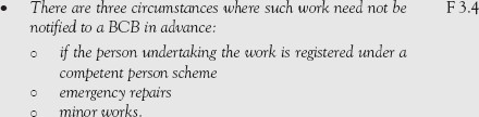
Where the work is of a minor nature as described in the schedule of non-notifiable work, the work must still comply with the relevant requirements but need not be notified to the BCB. Such work includes:
• replacement of parts
• the addition of an output or control device where testing and adjusting is not possible or would not affect the system’s energy efficiency
• provision of self-contained mechanical ventilation or air-conditioning.
![]() In most cases where it is proposed to carry out notifiable ventilation work on a building, the BCB has to be notified in advance via a Full Plans application or an initial notice given jointly with the Approved Inspector.
In most cases where it is proposed to carry out notifiable ventilation work on a building, the BCB has to be notified in advance via a Full Plans application or an initial notice given jointly with the Approved Inspector.
6.2.2.5.2 Historic buildings
Ventilation systems should not introduce a new or increased technical risk, or in any other way prejudice the use or character of the building, particularly historic buildings that are:
• listed buildings
• in conservation areas
p.309
• of architectural and historical interest
• of architectural and historical interest within national parks, Areas of Outstanding Natural Beauty, historic parks and gardens, registered battlefields, the curtilages of scheduled ancient monuments and World Heritage Sites
• of traditional construction with permeable fabric that both absorbs and readily allows the evaporation of moisture, as these are exempt from compliance with the Building Regulations.
![]() When undertaking work on, or in connection with, a building that falls within one of the classes above, the aim should be to provide adequate ventilation as far as is reasonably and practically possible without damaging the character of the building or increasing the risk of long-term deterioration of its fabric or fittings.
When undertaking work on, or in connection with, a building that falls within one of the classes above, the aim should be to provide adequate ventilation as far as is reasonably and practically possible without damaging the character of the building or increasing the risk of long-term deterioration of its fabric or fittings.
Many books have been written about the problems related to restoring historic buildings and, before considering any work of this nature, you would be advised to seek the advice of the Local Planning Authority’s Conservation Officer, particularly if you are contemplating:
• the restoration of a historic building that has been subject to previous inappropriate alteration (e.g. replacement windows, doors and rooflights)
• rebuilding a former historic building following a fire or major demolition
• making the building’s fabric able to ‘breathe’, in order to control moisture and potential long-term decay.
![]() In all cases, the overall aim should be to improve ventilation of a historic building without:
In all cases, the overall aim should be to improve ventilation of a historic building without:

![]() Note: The guidance given by English Heritage1 and in BS 7913 Principles of the conservation of historic buildings should be taken into account in determining appropriate ventilation strategies for building work in historic buildings.
Note: The guidance given by English Heritage1 and in BS 7913 Principles of the conservation of historic buildings should be taken into account in determining appropriate ventilation strategies for building work in historic buildings.

p.310

6.2.2.5.3 Live-work units

6.2.2.5.4 performance of ventilation system
The key aim of the requirement is that a ventilation system is provided which, under normal conditions, can limit the accumulation of moisture which could lead to mould growth, and pollutants originating within a building which would otherwise become a hazard to the health of the people in the building. This requirement may be achieved by providing a ventilation system which:

The use of ventilation systems in buildings result in energy being used to heat fresh air taken in from outside and, in mechanical ventilation systems, to move air into, out of and/or around the building. Consideration, therefore, should be given to employing heat recovery devices, efficient types of fan motor and/or energy-saving control devices in the ventilation system.
6.2.2.5.5 The purpose of ventilation

Common pollutants in a dwelling are moisture and combustion products from unflued appliances (e.g. gas, oil or solid fuel cookers) and chemical emissions from construction and consumer products.

![]() Note: The ventilation system capacity, if used appropriately, is usually sufficient to remove odours arising from normal occupant activities within a dwelling.
Note: The ventilation system capacity, if used appropriately, is usually sufficient to remove odours arising from normal occupant activities within a dwelling.
6.2.2.5.6 Types of ventilation

p.311

![]() Note: The ventilation systems and devices mentioned in this book are examples of those most commonly in use at the time of writing. Other ventilation systems and devices could provide acceptable solutions. Where this is the case, you should seek the advice of your BCB.
Note: The ventilation systems and devices mentioned in this book are examples of those most commonly in use at the time of writing. Other ventilation systems and devices could provide acceptable solutions. Where this is the case, you should seek the advice of your BCB.
![]() Trickle ventilators are intended to normally be left open in occupied rooms in dwellings. Trickle ventilators with automatic controls should also have a manual override, so that the occupant can close the ventilator to avoid draughts. For pressure-controlled trickle ventilators that are fully open at typical conditions (e.g. 1 Pa pressure difference), only a manual close option is recommended.
Trickle ventilators are intended to normally be left open in occupied rooms in dwellings. Trickle ventilators with automatic controls should also have a manual override, so that the occupant can close the ventilator to avoid draughts. For pressure-controlled trickle ventilators that are fully open at typical conditions (e.g. 1 Pa pressure difference), only a manual close option is recommended.
In dwellings, humidity-controlled devices should be available to regulate the humidity of the indoor air, and hence minimize the risk of condensation and mould growth. These are best installed as part of an extract ventilator in moisture-generating rooms (e.g. kitchen or bathroom). Humidity control is not considered appropriate for sanitary accommodation, where the dominant pollutant is normally odour. Other types of automatic control (e.g. trickle ventilators, ventilation fans, dampers and air terminal devices) may also be suitable for regulating ventilation devices in dwellings.
Buildings can currently achieve an air permeability down to around 2–4m3/h.m2 of envelope area at 50 Pa pressure difference through good design. However, it is expected to improve in the future owing to the UK’s commitment to higher energy efficiency and lower carbon emissions.
p.312
The three main controllable ventilation methods are listed in Table 6.2.3.
Table 6.2.3 Ventilation methods

6.2.2.5. 6.1 purge ventilation
Purge ventilation is a manually controlled type of ventilation that is used in rooms and spaces to rapidly dilute pollutants and/or water vapour. It can be achieved by natural means (such as an openable window or an external door) or by mechanical means (e.g. a fan).
![]() Note: For further guidance on purge ventilations, see BS 5925
Note: For further guidance on purge ventilations, see BS 5925
6.2.2.5.6.2 background ventilators and intermittent extract fans
The need for background ventilators will depend on the air permeability or airtightness of a building, where air permeability is defined as ‘the average volume of air (in cubic metres per hour) that passes through unit area of the building envelope (in square metres) when subject to an internal to external pressure difference of 50 Pa’.

Figure 6.2.3 Background ventilators and intermittent extract fans
6.2.2.5.7 Ventilation of rooms containing openable windows

![]() A window with a night latch position is not recommended because of the difficulty of measuring the equivalent area, the greater likelihood of draughts and the potential increased security risk in some locations.
A window with a night latch position is not recommended because of the difficulty of measuring the equivalent area, the greater likelihood of draughts and the potential increased security risk in some locations.

Table 6.2.4 Ventilation of rooms containing openable windows (i.e. located on an external wall)

p.313
6.2.2.5.8 Control of the ventilation system
Ventilation should be controllable so that it can maintain reasonable indoor air quality and avoid waste of energy. These controls can be either manual or automatic. Manually controlled trickle ventilators can be located over the window frames, in window frames, just above the glass or directly through the wall (see Figure 6.2.4).
![]()

![]() Note: Humidity control is not appropriate for sanitary accommodation, where the dominant pollutant is normally odour.
Note: Humidity control is not appropriate for sanitary accommodation, where the dominant pollutant is normally odour.

6.2.2.5.9 Ventilation effectiveness
Ventilation effectiveness is (as the term suggests) a measure of how well a ventilation system supplies air to the building’s occupants. From an energy-saving perspective, the higher the level of ventilation effectiveness, the more efficient the system will be in reducing pollutant levels in the occupant’s breathing zone. As this can result in quite significant energy savings, it has to be considered when designing and installing ventilation systems.
As the designer cannot be absolutely certain of the future occupancy and/or use of the building in terms of seating plan, location of computers and printers, etc., a ventilation effectiveness level of 1 (i.e. where the supply air is fully mixed with the room air before it is breathed by the occupants) should be assumed in his calculations.

![]() Note: For more details about ventilation effectiveness, see CIBSE Guide A.
Note: For more details about ventilation effectiveness, see CIBSE Guide A.
6.2.2.5.10 Noise
Noise (which may travel through ducts) generated by ventilation fans and noise from the fan unit may disturb the occupants of the building and so discourage their use in some circumstances.
The main issues to be addressed in minimizing the noise impact of the ventilation system are the noise from the fan unit entering the ducts, and the attenuation provided by the ducts, bends and junctions and the characteristics of the room grill.

6.2.2.5.11 Ducting
![]()
p.314
6.2.2.5.12 Commissioning

6.2.2.5.13 New dwellings
6.2.2.5.13.1 ventilation rates

Table 6.2.5 Whole building ventilation rates

p.315
6.2.2.5.13.2 extract ventilation requirements

Table 6.2.6 Extract ventilation rates

![]() Note: For greater occupancy, add 4 1/s per occupant.
Note: For greater occupancy, add 4 1/s per occupant.
6.2.2.5.13.3 ventilation systems for basements
When ventilating a basement, you should select one of the following ventilation systems (illustrated in Figure 6.2.4).
• Background ventilators and intermittent extract fans.
• Passive Stack Ventilation (PSV).
• Continuous Mechanical Extract (MEV).
• Continuous Mechanical Supply and Extract with Heat Recovery (MVHR).
Table 6.2.7 summarises the requirements for ventilation systems for basements listed below.

p.316


Figure 6.2.4 Ventilation systems
p.317
Table 6.2.7 Ventilation systems for basements


Figure 6.2.5 Two habitable rooms treated as a single room for ventilation purposes
![]() If the guidance on natural ventilation given in the Approved Document F (Ventilation) is not be appropriate for your situation, seek expert advice.
If the guidance on natural ventilation given in the Approved Document F (Ventilation) is not be appropriate for your situation, seek expert advice.
![]() The guidance in this Approved Document F has not been formulated to deal with the products of tobacco smoking, vaping or other forms of smoking.
The guidance in this Approved Document F has not been formulated to deal with the products of tobacco smoking, vaping or other forms of smoking.
6.2.2.5.13.4 ventilation of a habitable room through another room or a conservatory
The general ventilation rate for conservatories (and adjoining rooms) with a floor area greater than 30m2, can be achieved by using background ventilators (e.g. air bricks).


Figure 6.2.6 Ventilation for a habitable room through a conservatory
6.2.2.5.13.5 kitchens


![]() Note: Manual boost controls should also be provided in kitchens to guard against the possibility of a single centrally located switch being left in an incorrect mode of operation.
Note: Manual boost controls should also be provided in kitchens to guard against the possibility of a single centrally located switch being left in an incorrect mode of operation.
6.2.2.5.13.6 exceptions
The guidance in Approved Document F for new dwellings and work on existing buildings does not apply in the following cases:
• temporary buildings not intended to remain in place for more than 28 days
• detached single-storey buildings, with less than 30m2 floor area that do not contain any sleeping accommodation
• detached buildings of less than 15m2 floor area containing no sleeping accommodation
• ground level building extensions (e.g. conservatories, porches, covered yards, covered ways and/or car ports) with a floor area less than 30m2.
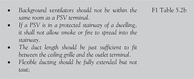
6.2.2.5.14 Passive stack ventilation
Passive Stack Ventilation (PSV) uses ducts from terminals mounted in the ceiling of rooms to terminals on the roof to extract air to the outside by a combination of the natural stack effect and the pressure effects of wind passing over the roof of the building.
The so-called ‘stack effect’ relies on the pressure differential between the inside and the outside of a building caused by differences in the density of the air due to an indoor–outdoor temperature difference.
p.318
Table 6.2.8 Passive Stack Ventilation

For sanitary accommodation only, purge ventilation may be used if security is not an issue.
6.2.2.5.14.1 PSV design
In designing PSV systems, the following requirements shall be met:

![]() Instead of PSV, an open-flued appliance may provide sufficient extract ventilation.
Instead of PSV, an open-flued appliance may provide sufficient extract ventilation.

p.319

Figure 6.2.7 PSV offset requirements
The design and installation of PSV systems are crucial to their operation, and Figure 6.2.8 shows the preferred option for kitchen and bathroom ducts with ridge terminals.

Figure 6.2.8 Preferred PSV system layouts
p.320

Figure 6.2.9 Alternative PSV system layouts
Another option (see Figure 6.2.9) is to have the kitchen and bathroom ducts penetrating the roof and extending their terminals to ridge height.
6.2.2.5.14.2 location of PSVs
![]() Note: Allow approximately 300mm extra to make smooth bends in an offset system.
Note: Allow approximately 300mm extra to make smooth bends in an offset system.
p.321
6.2.2.5.14.3 PSV controls

6.2.2.5.14.4 PSV terminals and ducts

p.322

p.323

![]() Note: Terminals should have an overall static pressure loss (upstream duct static minus test room static) equivalent to no more than four times the mean duct velocity pressure when measured at a static pressure difference of 10 Pa.
Note: Terminals should have an overall static pressure loss (upstream duct static minus test room static) equivalent to no more than four times the mean duct velocity pressure when measured at a static pressure difference of 10 Pa.

Figure 6.2.10 Flues penetrating compartment walls or floors
p.324

Figure 6.2.11 Correct installation of ducting

6.2.2.5.14.5 operation of PSVs in hot weather
Although PSV units should be capable of extracting sufficient air from wet rooms during the winter, in the summer months (when the temperature difference between the internal and external air is considerably reduced) they may not. To guard against this happening, purge ventilation should also be provided in wet rooms.
p.325

Figure 6.2.12 Incorrect installation of ducting
6.11.2.5.15 Purge ventilation

![]() Note: Appendix B Gives details of window and door sizing.
Note: Appendix B Gives details of window and door sizing.

6.2.2.5.16 External pollution
In urban areas, buildings are exposed to many pollution sources from varying heights and upwind distances (long, intermediate and short-range). Internal contamination from these pollution sources can have a detrimental effect on the buildings’ occupants, and so it is very important to ensure that the ventilation system provided is sufficient and, above all, that the air intake cannot be contaminated.
p.326
Typical urban pollutants include:
• carbon monoxide (CO)
• nitrogen dioxide (N02)
• sulphur dioxide (S02)
• ozone (03)
• particulate (PM10)
• benzene (C6H6)
• butadiene (C4H6)
• polycyclic aromatic hydrocarbons (PAHs)
• ammonia (NH3)
• lead (Pb).
Typical emission sources include:
• building ventilation system exhaust discharges
• combustion plants (e.g. heating appliances) running on conventional fuels
• construction and demolition sites
• discharges from industrial processes and other sources
• other combustion-type processes (such as waste incineration and thermal oxidation abatement schemes)
• road traffic, including traffic junctions and underground car parks
• uncontrolled discharges from industrial processes and other sources.
6.2.2.5.17 Indoor air pollutants
The maximum permissible level of indoor air pollutants is listed in Table 6.2.9.
Table 6.2.9 Maximum permissible level of indoor air pollutants

![]() Note: Mould growth can occur whether the dwelling is occupied or unoccupied, so the performance criteria for moisture (see Table 6.2.10) should be met at all times, regardless of occupancy. The other pollutants listed in Table 6.2.9 are harmful to the occupants only when the dwelling is occupied.
Note: Mould growth can occur whether the dwelling is occupied or unoccupied, so the performance criteria for moisture (see Table 6.2.10) should be met at all times, regardless of occupancy. The other pollutants listed in Table 6.2.9 are harmful to the occupants only when the dwelling is occupied.
Table 6.2.10 Mould growth

Extract ventilation concerns the removal of air directly from a space or spaces to outside. Extract ventilation may be by natural means such as PSV or by mechanical means (e.g. by an extract fan or central system).
![]() Extract fans lower the pressure in a building, which can cause combustion gases from open-flued appliances filling the room instead of going up the flue or chimney.
Extract fans lower the pressure in a building, which can cause combustion gases from open-flued appliances filling the room instead of going up the flue or chimney.

6.2.2.5.18 Equivalent ventilator area for dwellings
Designers should use the equivalent ventilator areas shown in Table 6.12.11 when designing systems using intermittent extract fans and background ventilators for multistorey dwellings that are more than four storeys above ground level and which have more than one exposed façade.
p.327
![]() Note: Equivalent area is defined as ‘the area of a sharp-edged orifice which air would pass at the same volume flow rate, under an identical applied pressure difference’.
Note: Equivalent area is defined as ‘the area of a sharp-edged orifice which air would pass at the same volume flow rate, under an identical applied pressure difference’.
1. For single-storey dwellings up to four storeys above ground level, add 5000mm2.
2. For an occupancy level greater than two persons in the main bedroom and one person in all other bedrooms, assume an extra bedroom for each additional person.
3. For more than five bedrooms, add an additional 10,000mm2 per bedroom.
p.328
Table 6.2.11 Equivalent ventilator area for dwellings

6.2.2.5.19 Ventilation air intakes
One method of achieving good indoor air quality is to reduce the amount of water vapour and/or air pollutants that are released into the indoor air, particularly those caused from construction and consumer products.
Air intakes that are located on a less polluted side of the building may be used for fresh air.
![]() Note: Further information about control of emissions from construction products is available in BRE Digest 464.
Note: Further information about control of emissions from construction products is available in BRE Digest 464.
6.2.2.5.20 Installation of fans in dwellings
The three fan types most commonly used in domestic applications are:
• axial fans:
![]() the most common form of fan
the most common form of fan
![]() can be mounted on the wall, on the window (i.e. through a suitable glazing hole) or in the ceiling:
can be mounted on the wall, on the window (i.e. through a suitable glazing hole) or in the ceiling:
![]() for wall and window mounting applications up to 350mm thick, use a short length of rigid round duct or a flexible duct pulled taut
for wall and window mounting applications up to 350mm thick, use a short length of rigid round duct or a flexible duct pulled taut
![]() for bathrooms, 100mm diameter fans can be used as axial fans in the ceiling with a short (1.5m maximum) length of flexible duct with (a maximum) two 90° bends.
for bathrooms, 100mm diameter fans can be used as axial fans in the ceiling with a short (1.5m maximum) length of flexible duct with (a maximum) two 90° bends.
• centrifugal fans:
![]() because they develop greater pressure, permit longer lengths of ducting to be used, and so can be utilized for most wall and/or window applications in high-rise (i.e. above three storeys) buildings or in exposed locations to overcome wind pressure
because they develop greater pressure, permit longer lengths of ducting to be used, and so can be utilized for most wall and/or window applications in high-rise (i.e. above three storeys) buildings or in exposed locations to overcome wind pressure
![]() most centrifugal fans are designed with 100mm diameter outlets, which enables them to be connected to a wide variety of duct types.
most centrifugal fans are designed with 100mm diameter outlets, which enables them to be connected to a wide variety of duct types.
• in-line fans:
![]() in-line axial fans, which have to be installed with the shortest possible duct length to the discharge terminal
in-line axial fans, which have to be installed with the shortest possible duct length to the discharge terminal
![]() in-line mixed flow fans, which have the characteristics of both axial and centrifugal fans and can, therefore, be used with longer lengths of ducting.
in-line mixed flow fans, which have the characteristics of both axial and centrifugal fans and can, therefore, be used with longer lengths of ducting.
![]() Both types can be used for bathrooms (100mm diameter), utility rooms (125mm diameter) and kitchens (150mm diameter.
Both types can be used for bathrooms (100mm diameter), utility rooms (125mm diameter) and kitchens (150mm diameter.
![]() Note: The duct must be pulled taut and the discharge terminal should have at least 85 percent free area of the duct diameter.
Note: The duct must be pulled taut and the discharge terminal should have at least 85 percent free area of the duct diameter.
p.329
6.2.2.5.20.1 fan terminals
When installing fans:

![]() Note: In these cases (only), the equivalent area may be assumed to be equal to the free area.
Note: In these cases (only), the equivalent area may be assumed to be equal to the free area.
6.2.2.5.20.2 intermittent extract fans

![]() In rooms with no natural light, the fans could be controlled by the operation of the main room light switch.
In rooms with no natural light, the fans could be controlled by the operation of the main room light switch.
p.330

Table 6.2.12 Extract ventilation rates

![]() Note: For sanitary accommodation, a purge ventilation system may be used, and in wet rooms a heat recovery ventilator may be used instead of a conventional fan, if it has the same extract rate.
Note: For sanitary accommodation, a purge ventilation system may be used, and in wet rooms a heat recovery ventilator may be used instead of a conventional fan, if it has the same extract rate.


p.331

Figure 6.2.13 Single-sided ventilation

Figure 6.2.14 Background ventilation systems

p.332
6.2.2.5.21 Location of background ventilators in rooms

6.2.2.5.22 Trickle ventilators
Manually controlled trickle ventilators are widely used for background ventilation and these can be located as shown in Figure 6.2.15.
To avoid cold draughts, trickle ventilators are normally positioned 1.7m above floor level, and usually include a simple control (such as a flap) to allow users to shut off the ventilation according to personal choice or external weather conditions. Nowadays, pressure-controlled trickle ventilators that reduce the air flow according to the pressure difference across the ventilator are available to reduce draught risks during windy weather.
Trickle ventilators are normally left open in occupied rooms in dwellings.

p.333
6.2.2.5.23 Continuous mechanical extract

Figure 6.2.15 Continuous mechanical extract
This system may consist of either a central extract system or individual room fans, or a combination of both.
To calculate the required extract rate, first determine the whole-building ventilation rate from Table 6.2.5.
For sanitary accommodation only, purge ventilation may be used if security is not an issue.
p.334
6.2.2.5.23.1 continuous mechanical extract – requirements

![]() Where ducts etc. are provided in a dwelling with a protected stairway, precautions may be necessary to avoid the possibility of the system allowing smoke or fire to spread into the stairway.
Where ducts etc. are provided in a dwelling with a protected stairway, precautions may be necessary to avoid the possibility of the system allowing smoke or fire to spread into the stairway.
6.2.2.5.23.2 continuous mechanical supply and extract with heat recovery
To calculate the air flow rate of a building using continuous mechanical supply and extract with heat recovery (i.e. MVHR), first determine the whole-building ventilation rate from Table 6.2.5 then, depending on whether it is a multistorey or single-storey building, subtract the gross internal volume of dwelling heated space (m2) as follows:
• Multistorey dwelling Whole-building ventilation rate − 0.04 × gross internal volume
• Single-storey dwelling Whole-building ventilation rate − 0.06 × gross internal volume
Next, work out the whole dwelling air extract rate at maximum operation by summing the individual room rates from Table 6.2.12.

Figure 6.2.16 Continuous mechanical supply – with heat recovery
6.2.2.5.24 Mechanical intermittent extract
As odour is the main pollutant, humidity controls should not be used for intermittent extract in sanitary accommodation.
p.335

![]() Note: In dwellings, humidistat controls should be available to regulate the humidity of the indoor air and, to minimize the risk of condensation and mould growth, should be installed as part of an extract ventilator, especially in moisture-generating rooms such as a kitchen or a bathroom. They should not be used for sanitary accommodation, where the dominant pollutant is usually odour.
Note: In dwellings, humidistat controls should be available to regulate the humidity of the indoor air and, to minimize the risk of condensation and mould growth, should be installed as part of an extract ventilator, especially in moisture-generating rooms such as a kitchen or a bathroom. They should not be used for sanitary accommodation, where the dominant pollutant is usually odour.

p.336
6.2.2.5.24.1 operation

p.337

![]() Note: Extract terminals located on the prevailing windward façade should be protected against the effects of wind by using ducting to another façade, using a constant-volume flow rate unit or a central extract system.
Note: Extract terminals located on the prevailing windward façade should be protected against the effects of wind by using ducting to another façade, using a constant-volume flow rate unit or a central extract system.
p.338

p.339

6.2.2.5.25 The effects of solar gains in summer
Solar gains are certainly beneficial in winter, as they reduce the demand for heating. However, they can cause overheating in the summer.
To overcome this problem during the summer (and whenever possible), the effects of solar gain should be limited by a suitable combination of window size and orientation, shading, solar control measures, ventilation (day and night) and high thermal capacity.
If ventilation is provided using a balanced mechanical system, consideration should be given to providing a summer bypass function for use during warm weather (or allow the dwelling to operate via natural ventilation) so that the ventilation is more effective in reducing overheating.
![]() Although many buildings are equipped with air-conditioning for comfort, these are high energy users and their use should, whenever possible, be limited. This can be achieved by either reducing the need for air-conditioning or reducing the installed capacity of any air-conditioning system that is installed.
Although many buildings are equipped with air-conditioning for comfort, these are high energy users and their use should, whenever possible, be limited. This can be achieved by either reducing the need for air-conditioning or reducing the installed capacity of any air-conditioning system that is installed.
6.2.2.5.26 Access for maintenance

6.2.2.5.27 Exhaust outlets
Exhaust outlets should be located so that re-entry, or ingestion, into the building and/or other nearby buildings is minimized. This can be achieved by ensuring that:

p.340

![]() Note: Where possible, pollutants from stacks should be grouped together and discharged vertically upwards.
Note: Where possible, pollutants from stacks should be grouped together and discharged vertically upwards.
6.2.2.5.28 Work on existing buildings
Under the Building Regulations, windows are a controlled fitting. These clauses, therefore, make it mandatory that, when windows in an existing building are replaced, then the replacement work:
• shall comply with the requirements of Approved Document L (Conservation of fuel and power).
• shall not have a worse level of compliance with other applicable Approved Documents of Schedule 1, in particular Approved Documents B (Fire safety), F (Ventilation) and J (Combustion appliances and fuel storage systems).
6.2.2.5.28.1 replacement windows

Table 6.2.13 Equivalent areas for replacement windows – dwellings
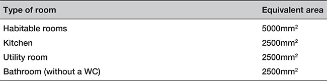
p.341
Table 6.2.14 Equivalent areas for replacement windows – buildings other than dwellings


Figure 6.2.17 Window dimensions
![]() Note: The window opening area is the dimensions of the open area: height (H) × width (W).
Note: The window opening area is the dimensions of the open area: height (H) × width (W).

p.342

![]() Note: Approved Document B (Fire safety) includes provisions for the size of escape windows. The larger of the provisions in Approved Document B or F (Ventilation) should apply in all cases.
Note: Approved Document B (Fire safety) includes provisions for the size of escape windows. The larger of the provisions in Approved Document B or F (Ventilation) should apply in all cases.
6.2.2.5.28.2 the addition of a habitable room
The general ventilation rates for an additional habitable room (not including a conservatory) to an existing building may be achieved by using background ventilators, heat recovery ventilators and/or purge ventilation.

p.343

6.2.2.5.28.3 single room heat recovery ventilator
If a Single Room Heat Recovery Ventilator (SRHRV) is used to ventilate a habitable room, to calculate the air flow rate, first determine the whole-building ventilation rate from Table 6.2.5, and then work out the room supply rate using the following formula:
![]()
When working out the continuous mechanical extract for a whole building, which also includes a room ventilated by an SRHRV, the following formula should be used:
![]()
6.2.2.5.28.4 the addition of a wet room to an existing building

p.344

Table 6.2.15 Ventilation systems for basements

6.2.2.5.29 Roofs
6.2.2.5.29.1 roof with a pitch of 15° or more
Pitched roof spaces should have ventilation openings at least 10mm wide at eaves level to promote cross-ventilation. A pitched roof that has a single slope and abuts a wall should have ventilation openings at eaves level at least 10mm wide and at high level (i.e. at the junction of the roof and the wall) at least 5mm wide.
Roof spaces should have ventilation openings at least 25mm wide in two opposite sides to promote cross-ventilation. The void should have a free air space of at least 50mm between the roof deck and the insulation. Pitched roofs where the insulation follows the pitch of the roof need ventilation at the ridge at least 5mm wide.
Where the edges of the roof abut a wall or other obstruction in such a way that free air paths cannot be formed to promote cross-ventilation, or the movement of air outside any ventilation openings would be restricted, an alternative form of roof construction should be adopted.

Figure 6.2.18 Ventilating roof voids: (a) Pitched roof (b) Lean-to roof

Figure 6.2.19 Ventilating roof void – flat roof with a pitch of less than 15°
![]() Roofs with a span exceeding 10m may require more ventilation totalling 0.6 percent of the roof area.
Roofs with a span exceeding 10m may require more ventilation totalling 0.6 percent of the roof area.
Ventilation openings may be continuous or distributed along the full length and may be fitted with a screen, fascia, baffle, etc.
Where necessary (e.g. for the purposes of health and safety), ventilation to small roofs such as those over porches and bay windows should always be provided and a roof that has a pitch of 70° or more shall be insulated as though it were a wall.
![]() If the ceiling of a room follows the pitch of the roof, ventilation should be provided as if it were a flat roof.
If the ceiling of a room follows the pitch of the roof, ventilation should be provided as if it were a flat roof.
p.345
6.2.2.5.29.2 passive stack ventilation in roof spaces:

![]() Note: Placing the outlet terminal at the ridge of the roof is the preferred option, as it is not prone to wind gusts and/or certain wind directions.
Note: Placing the outlet terminal at the ridge of the roof is the preferred option, as it is not prone to wind gusts and/or certain wind directions.
p.346
6.2.2.5.30 Existing buildings
The requirements for ventilation to an existing building which is going to have an additional habitable room (not including a conservatory) will depend on whether the existing building has windows opening to outside and the amount of background ventilation it possesses. Basically:
• if the additional room is connected to an existing habitable room which still has windows opening to outside and with a total background ventilation equivalent area of at least 5000mm2 then the guidance in Approved Document F5.15 should be followed
• if the existing habitable room does not have windows opening to the outside, then it may be ventilated through an additional room via background ventilation of at least 8000mm2 equivalent area between the two rooms, and background ventilators of at least 8000mm2 equivalent area between the additional room and outside.
6.2.2.5.30.1 the addition of a conservatory to an existing building
If a conservatory is added to an existing habitable room which does not have windows opening to the outside, then the habitable room may be ventilated through the conservatory provided that there is background ventilation of at least 8000mm2 equivalent area between the habitable room and the conservatory, and background ventilation of at least 8000mm2 equivalent area between the additional room and outside.
p.347
6.2.2.5.30.2 refurbishing a kitchen or bathroom in an existing dwelling
If any of the work being carried out in the kitchen of an existing building is ‘building work’ then you will need to comply with the appropriate requirements of this Regulation.

p.348
![]() Note: The guidance within the Approved Document F may not be adequate to address pollutants from flueless combustion space heaters or from occasional, occupant-controlled events such as painting, smoking, cleaning or other high-polluting events. Extract ventilation may be by natural means (e.g. by PSV or by mechanical means such as an extract fan or central system).
Note: The guidance within the Approved Document F may not be adequate to address pollutants from flueless combustion space heaters or from occasional, occupant-controlled events such as painting, smoking, cleaning or other high-polluting events. Extract ventilation may be by natural means (e.g. by PSV or by mechanical means such as an extract fan or central system).
6.2.2.6 Drainage and waste disposal

6.2.2.7 Combustion appliances and fuel storage systems
6.2.2.7.1 Ensuring adequate ventilation

p.349
6.2.2.7.2 Permanently open air vents

p.350


Figure 6.2.20 Locating permanent air vent openings (examples)
p.351
![]() Note: A way to meet the requirement would be to size permanently open air vents so that their equivalent area is sufficient for the appliance(s) to be installed (taking account where necessary of obstructions such as grilles and anti-vermin mesh), and to site them:
Note: A way to meet the requirement would be to size permanently open air vents so that their equivalent area is sufficient for the appliance(s) to be installed (taking account where necessary of obstructions such as grilles and anti-vermin mesh), and to site them:
• outside fireplace recesses and beyond the hearths of open fires so that dust or ash will not be disturbed by draughts; or
• in a location unlikely to cause discomfort from cold draughts.


Figure 6.2.21 Ventilator free areas
p.352
6.2.2.7.3 Noise attenuation

6.2.2.7.4 Transfer ventilation

6.2.2.7.5 Ventilation ducts

6.2.2.7.6 Flueless appliances

![]() Note: Openable elements installed for the rapid ventilation of rooms, and other provisions made for the rapid ventilation of kitchens, may be acceptable for flueless appliances in those locations.
Note: Openable elements installed for the rapid ventilation of rooms, and other provisions made for the rapid ventilation of kitchens, may be acceptable for flueless appliances in those locations.
Ways of meeting the requirement when installing flueless cookers (including ovens, grills or hotplates), flueless water heaters and flueless space heaters are shown in Figure 6.2.22.

Figure 6.2.22 Ventilation for flueless gas appliances
p.353
6.2.2.7.7 Extract ventilation

6.2.2.7.8 Flued appliances other than decorative fuel-effect fires

p.354

Figure 6.2.23 Free areas of permanently open air vents for gas appliances (excluding decorative fuel-effect fires)
6.2.2.7.9 Airtightness of the dwelling

p.355
Individual rooms in some older houses with solid walls and solid floors can be inherently airtight when fitted with modern glazing. The situation may, therefore, need to be assessed with respect both to the overall dwelling and to the individual room where the appliance is to be fitted.
p.356
![]() If in doubt, assume that the air permeability is lower than 5.0m3/ (h.m2) at 50 Pa and fit the appropriate permanent ventilation or seek specialist advice. (Further information can be found in GPG224 Improving airtightness in dwellings).
If in doubt, assume that the air permeability is lower than 5.0m3/ (h.m2) at 50 Pa and fit the appropriate permanent ventilation or seek specialist advice. (Further information can be found in GPG224 Improving airtightness in dwellings).
p.357
6.2.2.7.10 Ventilation of LPG and oil storage tanks


Figure 6.2.24 Location of LPG cylinders
![]() Thatched roofs can sometimes be vulnerable to spontaneous combustion caused by heat transferred from flues building up in thick layers of thatch that are in contact with the chimney. To reduce the risk, it is recommended that rigid twin-walled insulated metal flue liners are used within a ventilated (top and bottom) masonry chimney void, as long as they are adequately supported and not in direct contact with the masonry. Non-metallic chimneys and cast in-situ flue liners can also be used if the heat transfer to the thatch is assessed in relation to the depth of thatch and risk of spontaneous combustion.
Thatched roofs can sometimes be vulnerable to spontaneous combustion caused by heat transferred from flues building up in thick layers of thatch that are in contact with the chimney. To reduce the risk, it is recommended that rigid twin-walled insulated metal flue liners are used within a ventilated (top and bottom) masonry chimney void, as long as they are adequately supported and not in direct contact with the masonry. Non-metallic chimneys and cast in-situ flue liners can also be used if the heat transfer to the thatch is assessed in relation to the depth of thatch and risk of spontaneous combustion.
p.358
6.2.2.8 Protection from falling, collision and impact
![]() Regulations regarding the requirements for opening, closing or adjusting windows, skylights and ventilators are also contained in Regulation 15(1) of the Workplace (Health, Safety and Welfare) Regulations 1992.
Regulations regarding the requirements for opening, closing or adjusting windows, skylights and ventilators are also contained in Regulation 15(1) of the Workplace (Health, Safety and Welfare) Regulations 1992.


Figure 6.2.25 Marking by a barrier

p.359

Figure 6.2.26 Height of controls
6.2.2.9 Conservation of fuel and power
![]() Note: The ‘energy performance of a building’ means the calculated or measured amount of energy needed to meet the energy demand associated with a typical use of the building, which includes, inter alia, energy used for heating, cooling, ventilation, hot water and lighting.
Note: The ‘energy performance of a building’ means the calculated or measured amount of energy needed to meet the energy demand associated with a typical use of the building, which includes, inter alia, energy used for heating, cooling, ventilation, hot water and lighting.

p.360

![]() For ventilation systems, an approved procedure would be to follow the guidance in the Domestic Ventilation Compliance Guide.
For ventilation systems, an approved procedure would be to follow the guidance in the Domestic Ventilation Compliance Guide.
p.361
6.3.1 Requirements

p.362

p.363

6.3.2 Meeting the requirements
6.3.2.1 Fire safety
6.3.2.1.1 Openings in compartmentation and cavity barriers
p.364
6.3.2.1.2 Openings for pipes

Table 6.3.1 Maximum nominal internal diameter of pipes passing through a fire separating element

Table 6.3.2 Specific provisions of test for fire resistance of elements of structure – casings around a drainage system

p.365

Figure 6.3.1 Pipes penetrating a structure

Figure 6.3.2 Enclosure for drainage or water supply pipes – dwellings with any number of storeys
6.3.2.1.3 Fire-stopping

6.3.2.2 Site preparation and resistance to moisture
6.3.2.2.1 Subsoil drainage

6.3.2.2.2 Flood risk

p.366

![]() Note: Flooding can create blockages in drains and sewers that can lead to backflow of sewage into properties through low-level drain gullies, toilets, etc.
Note: Flooding can create blockages in drains and sewers that can lead to backflow of sewage into properties through low-level drain gullies, toilets, etc.

Figure 6.3.3 Subsoil drain cut during excavation
6.3.2.2.3 Protection against groundwater


Figure 6.3.4 Suspended floor – preventing water collection
6.3.2.2.4 External walls

p.367
6.3.2.2.5 Joints between doors and windows

p.368
6.3.2.2.6 Roofs

6.3.2.3 Resistance to the passage of sound
6.3.2.3.1 Junction requirements for walls and floors

![]() To reduce flanking transmission and avoid air paths, pay special attention to workmanship and detailing at the perimeter and wherever a pipe or duct penetrates the floor.
To reduce flanking transmission and avoid air paths, pay special attention to workmanship and detailing at the perimeter and wherever a pipe or duct penetrates the floor.
p.369

Figure 6.3.5 Floor penetrations
6.3.2.4 Sanitation, hot water safety and water efficiency
6.3.2.4.1 Non-notifiable work

6.3.2.4.2 Discharge to drains

p.370
![]() Note: Where greywater recycling is used, lower overall flows are to be expected (particularly at the head of the drain) this should be taken into account in drain design.
Note: Where greywater recycling is used, lower overall flows are to be expected (particularly at the head of the drain) this should be taken into account in drain design.
6.3.2.5 Drainage and waste disposal
![]() Laying and maintaining drains are hazardous operations. Appropriate safety codes should be followed including procedures for working in confined spaces. Safe working procedures and permits to work may be required in some situations.
Laying and maintaining drains are hazardous operations. Appropriate safety codes should be followed including procedures for working in confined spaces. Safe working procedures and permits to work may be required in some situations.
6.3.2.5.1 Sanitary pipework
6.3.2.5.1.1 traps
![]() Note: All points of discharge into the system should be fitted with a trap (e.g. a water seal) to prevent foul air from the system entering the building.
Note: All points of discharge into the system should be fitted with a trap (e.g. a water seal) to prevent foul air from the system entering the building.

Figure 6.3.5 Floor penetrations
p.371
6.3.2.5.1.2 branch discharge pipes
Note: If an appliance is on the ground floor, the pipe(s) may discharge to a stub stack, discharge stack, direct to a drain or (if the pipe carries only wastewater) or a gully.

In single dwellings (up to three storeys) branch discharge pipes should not discharge into a stack lower than 450mm above the invert of the tail bend at the foot of the stack. In certain cases a stub stack may be used (see Figure 6.3.6).


![]() Note: A branch pipe serving a ground floor appliance may discharge direct to a drain or into its own stack.
Note: A branch pipe serving a ground floor appliance may discharge direct to a drain or into its own stack.

p.372

Figure 6.3.6 Stub stack

Figure 6.3.7 Direct connection of ground floor WC to drain
p.373

Figure 6.3.8 Branch discharge stack

Figure 6.3.9 Branch connections
p.374


Figure 6.3.10 Branch connections
p.375

Table 6.3.4 Common branch discharge pipes

![]() Note:
Note:
1. A separate ventilating stack is only preferred where the numbers of sanitary appliances and their distance to a discharge stack are large.
2. A dry stack may provide ventilation for branch ventilation pipes.
3. Ventilation stacks serving buildings with not more than ten storeys and containing only dwellings should be at least 32mm diameter.
p.376


Figure 6.3.11 Branch ventilation pipes
A separate ventilating stack is only likely to be preferred where the numbers of sanitary appliances and their distance to a discharge stack are large.
p.377
6.3.2.5.1.3 discharge stacks

6.3.2.5.1.4 materials for pipes fittings and joints

p.378

Figure 6.3.12 Termination of ventilation stacks

6.3.2.5.2 Foul drainage
‘Foul drainage’ includes all underground drains and sewers from buildings to the point of connection to an existing sewer or a cesspool or wastewater treatment system plus any drains or sewers outside the curtilage of the building.
![]() You should make sure pipework is well maintained at all times as defective pipework is known to harbour rats.
You should make sure pipework is well maintained at all times as defective pipework is known to harbour rats.
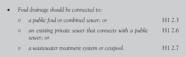
p.379

![]() Note: Anti-flooding valves should preferably be of the double valve type, and should be suitable for foul water and have a manual closure device.
Note: Anti-flooding valves should preferably be of the double valve type, and should be suitable for foul water and have a manual closure device.

![]() Pipes should (wherever possible) be laid in straight lines. Changes of direction and gradient should be minimized.
Pipes should (wherever possible) be laid in straight lines. Changes of direction and gradient should be minimized.

p.380
![]() Drainage serving kitchens in commercial hot food premises should be fitted with a grease separator complying with BS EN 1825–1.
Drainage serving kitchens in commercial hot food premises should be fitted with a grease separator complying with BS EN 1825–1.
6.3.2.5.2.1 rodent control
If the site has been previously developed, the Local Authority should be consulted to determine whether any special measures are necessary for control of rodents. Special measures which may be taken include:


p.381
6.3.2.5.2.2 protection from settlement


![]() Note: Where pipes are to be laid on piles or beams or in a common trench, or where the ground may prove unstable, particularly where there is a high water table, advice may be found in TRL’s A Guide to the Design Loadings for Buried Rigid Pipes. The Local Authority may be able to provide information regarding the site.
Note: Where pipes are to be laid on piles or beams or in a common trench, or where the ground may prove unstable, particularly where there is a high water table, advice may be found in TRL’s A Guide to the Design Loadings for Buried Rigid Pipes. The Local Authority may be able to provide information regarding the site.

Figure 6.3.13 Pipe embedded in the wall. Short length of pipe embedded in a wall with joints within 150mm of either wall face. Additional rocker pipes (maximum length 600mm) with flexible joints are then added

p.382

Figure 6.3.14 Pipe shielded by a lintel. Both sides are masked with rigid sheet material (to prevent entry of fill or vermin) and the void is filled with a compressible sealant to prevent entry of gas

Figure 6.3.15 Pipe runs near buildings
p.383
6.3.2.5.2.3 pipe gradients and sizes

Table 6.3.5 Flow rates from dwellings


Table 6.3.6 Recommended minimum gradients for foul drains

p.384
6.3.2.5.2.4 pumping installations
Where gravity drainage is impracticable, or protection against flooding due to surcharge in downstream sewers is required, a pumping installation will be needed.
![]() Note: Package pumping installations suitable for installation within buildings are available and floor-mounted units may be particularly suited for installing in basements.
Note: Package pumping installations suitable for installation within buildings are available and floor-mounted units may be particularly suited for installing in basements.

Although flood resistance is not currently a requirement of the Building Regulations, as part of its aim to improve the energy efficiency of buildings and use planning to protect the environment, the revised 2013 National Planning Policy Framework sets out policies that aim to avoid inappropriate development in areas at risk of flooding, including requiring new development to be flood resilient and resistant, as and where appropriate. See www.gov.uk/government/uploads/system/uploads/attachment_data/file/6077/2116950.pdf for full details.
![]() Further information on flood-resistant and -resilient construction can be found in the Defra 2007 publication Improving the Flood Performance of New Buildings: Flood Resilient Construction.
Further information on flood-resistant and -resilient construction can be found in the Defra 2007 publication Improving the Flood Performance of New Buildings: Flood Resilient Construction.
6.3.2.5.25 bedding and backfill
![]() Pipes need to be protected from damage, particularly pipes which could be damaged by the weight of backfilling.
Pipes need to be protected from damage, particularly pipes which could be damaged by the weight of backfilling.

p.385
Table 6.3.7 Materials for below-ground gravity drainage

![]() Special precautions should be taken to take account of the effects of settlement where pipes run under or near buildings.
Special precautions should be taken to take account of the effects of settlement where pipes run under or near buildings.
The depth of the pipe cover will usually depend on the levels of the connections to the system and the gradients at which the pipes should be laid and the ground levels.


Figure 6.3.16 Bedding for rigid pipes
p.386


Figure 6.3.17 Bedding for flexible pipes


Figure 6.3.18 Protection of pipes laid in shallow depths
p.387


Figure 6.3.19 Joints for concrete encased pipes
6.3.2.5.2.6 access points
Sufficient and suitable access points should be provided for clearing blockages from drain runs that cannot be reached by any other means.
p.388
![]() Note: Inspection chambers and manholes should have removable non-ventilating covers of durable material (e.g. cast iron, steel, precast concrete or uPVC).
Note: Inspection chambers and manholes should have removable non-ventilating covers of durable material (e.g. cast iron, steel, precast concrete or uPVC).

p.389

![]() All pipework carrying greywater for reuse should be clearly marked with the word ‘GREYWATER’.
All pipework carrying greywater for reuse should be clearly marked with the word ‘GREYWATER’.
6.3.2.5.2.7 power to examine and test

6.3.2.5.2.8 repair, reconstruction or alterations to underground drains or sewers

p.390

6.3.2.5.2.9 sealing or removal of disused drains or sewers
Disused drains and sewers offer ideal harbourage to rats and frequently offer a route for them to move between sewers and the surface. The drains and sewers could also collapse, causing subsidence, and the person who completes work that results in any part of a drain becoming permanently disused is responsible for ensuring that the drain is sealed at such points as the Local Authority may direct.

p.391
6.3.2.5.3 Wastewater treatment systems and cesspools
The use of non-mains foul drainage, such as wastewater treatment systems, septic tanks or cesspools, should only be considered where connection to mains drainage is not practicable.
Any discharge from a wastewater treatment system is likely to require consent from the Environment Agency.

6.3.2.5.3.1 septic tanks
Septic tanks provide suitable conditions for the settlement, storage and partial decomposition of solids, which need to be removed at regular intervals. The discharge can, however, still be harmful and will require further treatment from either a drainage field/mound or constructed wetland.

Figure 6.3.20 Basic septic tank
The principle of a septic tank is very simple.
Wastewater flows from the house to the septic tank. The tank is designed to retain wastewater and allow heavy solids to settle to the bottom. These solids are partially decomposed by bacteria to form sludge. Grease and light particles float, forming a layer of scum on top of the wastewater. Baffles installed at the inlet and outlet of the tank help prevent scum and solids from escaping.

Figure 6.3.21 Septic tank principles
A solid pipe leads from the septic tank to a distribution box where the wastewater is channelled into one or more perforated pipes set in trenches of gravel. Here the water slowly seeps into the underlying soil. Dissolved wastes and bacteria in the water are trapped or adsorbed to soil particles or decomposed by micro-organisms. This process removes disease-causing organisms, organic matter and most nutrients. The purified wastewater then moves to the groundwater or evaporates from the soil. Trench systems are the most common type of system used in new home construction.
p.392

p.393

![]() For septic tanks, cesspools, packaged treatment works and drainage fields a notice should be fixed within the building describing the necessary maintenance.
For septic tanks, cesspools, packaged treatment works and drainage fields a notice should be fixed within the building describing the necessary maintenance.

6.3.2.5.3.2 drainage fields and mounds

p.394


Figure 6.3.22 Drainage field

p.395

p.396

p.397
6.3.2.5.3.3 packaged treatment works
Packaged treatment works are used where it is either unacceptable or impractical to install a septic tank and a connection to a mains sewer impossible. These plants are particularly useful for situations where intermittent flow, very low flow and seasonal fluctuating flow rates cause serious problems for other sewage treatment systems. They are ideal for campsites and caravan parks and pubs.
The system comprises a small electrically driven plant and is usually contained within a single tank. The waste passes through three stages, initial settlement, biozone (treatment), final settlement before it is discharged into a land drainage system.

6.3.2.5.3.4 cesspools
A cesspool is a watertight tank, installed underground, for the storage of sewage. No treatment is involved.
![]() Note: A filling rate of 150 litres per person per day is assumed, and if the cesspool does not fill within the estimated period the tank should be inspected for leakage.
Note: A filling rate of 150 litres per person per day is assumed, and if the cesspool does not fill within the estimated period the tank should be inspected for leakage.

p.398
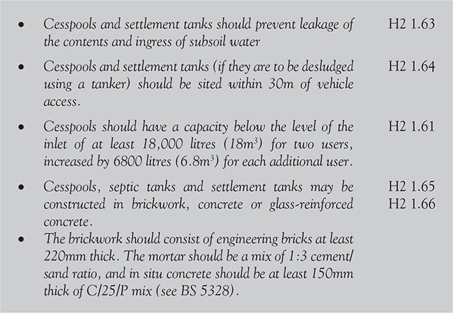
![]() Factory-made cesspools and septic tanks are available in glass-reinforced plastic, polyethylene or steel.
Factory-made cesspools and septic tanks are available in glass-reinforced plastic, polyethylene or steel.
6.3.2.5.3.5 greywater and rainwater tanks
Greywater and rainwater tanks should:

6.3.2.4.5 Rainwater drainage

p.399

6.3.2.5.4.1 gutters and rainwater pipes
Although the Building Regulations only actually applies to draining the rainfall from areas of 6m2 or more (unless they receive a flow from a rainwater pipe or from paved and/or other hard surfaces), each case should be considered on its own merits separately and a decision made. This particularly applies to small roofs and balconies. Table 6.25 shows the largest effective area that should be drained into the gutter sizes most often used.
For eaves gutters the design rainfall intensity should be 0.021 1/s/m2. In some cases, eaves drop systems may be used.

![]() Gutters should be laid with any fall towards the nearest outlet.
Gutters should be laid with any fall towards the nearest outlet.
Table 6.3.8 Calculation of drained area

p.400

Table 6.3.9 Gutter and outlet sizes

p.401

![]() Gutters and rainwater pipes should be firmly supported without restricting thermal movement.
Gutters and rainwater pipes should be firmly supported without restricting thermal movement.
6.3.2.5.4.2 drainage of paved areas

p.402

6.3.2.5.4.3 surface water drainage
Discharge to a watercourse may require consent from the Environment Agency, which may limit the rate of discharge. Where other forms of outlet are not practicable, discharge should be made to a sewer. For design purposes, a rainfall interval of 0.014 1/s/m2 can be assumed as normal.
![]() Note: The following guidance applies to surface water drainage systems for small catchments with impervious areas up to 2 hectares.
Note: The following guidance applies to surface water drainage systems for small catchments with impervious areas up to 2 hectares.

p.403

Under Section 85 (Offences concerning the polluting of controlled waters) of the Water Resources Act 1991, it is an offence to discharge any noxious or polluting material into a watercourse, coastal water or underground water. Most surface water sewers discharge to watercourses.
Under Section 111 (Restrictions on use of public sewers) of the Water Industry Act 1991, it is an offence to discharge petrol, chemical, waste steam or any matter likely to damage the drain into any drain or sewer connected to a public sewer.
p.404
6.3.2.5.5 sewers
If the property is connected to the public sewer, that sewer and any shared sewer pipes or pipes beyond the boundary of that property are the responsibility of the local utility company (see Figure 6.3.23).
![]() Responsibilities for sewers and drains changed in October 2011. Before then, you (as owner) were responsible for pipes within your own boundary.
Responsibilities for sewers and drains changed in October 2011. Before then, you (as owner) were responsible for pipes within your own boundary.

Figure 6.3.23 Typical sewer pipe responsibility
The most common problem with new connections happens when a property has separate pipes for foul water and for rainwater. It is vitally important that these two pipes are connected to the right parts of the public sewer network.
If you are in the process of building a new property or extension that will require a connection to the public sewer, you will need written permission from the utility company responsible before you’re allowed start. This is in addition to planning permission. You should apply for a sewer connection once you have obtained planning permission (or 12 months before you want to connect if planning permission is not required). Once you have received written approval from the utility company, you or your builder must then apply for permission to carry out the work.
Your local utility company will have a section on its website which explains the process in greater detail, together with all the documentation needed to apply. Details of which utility company covers your area can be found on the Water UK website (www.water.org.uk/consumers/find-your-supplier).
The first preference should always be to provide separate foul and surface water sewerage systems. Where ‘combined’ or ‘partially combined’ sewerage is unavoidable, then the design and construction of the shared sewer should be in accordance with the Protocol on Design, Construction and Adoption of Sewers in England and Wales (see archive.defra.gov.uk/environment/quality/water/industry/sewers/documents/sewer-protocol-rev07.pdf for details) to prevent the proliferation of private sewers and the associated problems of ownership and maintenance.
p.405

6.3.2.5.5.1 building over existing sewers

p.406

6.3.2.6 Combustion appliances and fuel storage systems
6.3.2.6.1 Location of flues

p.407

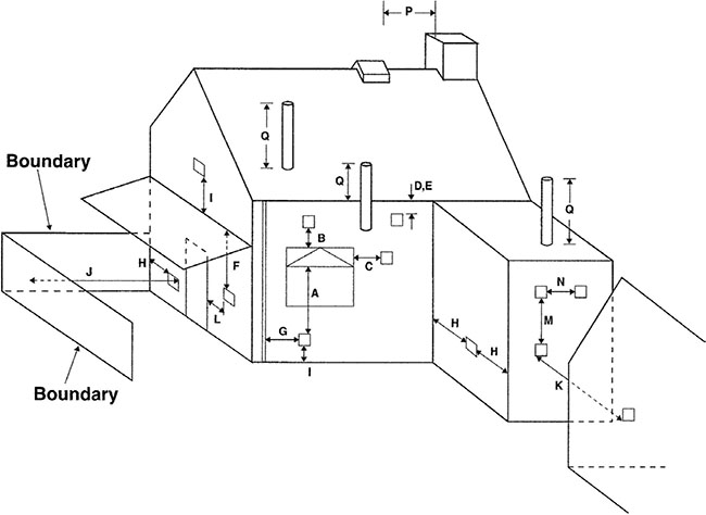
Figure 6.3.24 Location of outlets from flues serving gas appliances


Figure 6.3.25 Location of outlets from flues serving oil appliances
p.408
6.3.2.6.2 Location and support of cylinders


Figure 6.3.26 Example of accessible WC/cloakroom layout

Figure 6.3.27 Example of accessible bathroom layout
p.409
6.3.2.7 Access to and use of buildings
Where the dwelling provides an accessible bathroom:

p.410
A basement storey is storey with a floor which at some point is more than 1200mm below the highest level of ground adjacent to the outside walls. Basements are not included in counting the number of storeys in a building.
Unless you have the consent of the Local Authority, you are not allowed to construct a cellar or room in (or as part of) a house, an existing cellar, a shop, inn, hotel or office if the floor level of the cellar or room is lower than the ordinary level of the subsoil water on, under or adjacent to the site of the house.
![]() This does not, however, apply to the construction of a cellar or room carried out in accordance with plans deposited on an application under the Licensing Act 2003.
This does not, however, apply to the construction of a cellar or room carried out in accordance with plans deposited on an application under the Licensing Act 2003.
6.4.1 Requirements
![]() If the owner of the dwelling allows a cellar (or room forming part of it) to be used in a manner known to be in contravention of the Building Regulations, they are liable, on summary conviction, to a fine.
If the owner of the dwelling allows a cellar (or room forming part of it) to be used in a manner known to be in contravention of the Building Regulations, they are liable, on summary conviction, to a fine.
p.411

6.4.2 Meeting the requirements
6.4.2.1 Fire safety
6.4.2.1 1 Means of escape
6.4.2.1.1.1 emergency egress windows and external doors


Figure 6.4.1 Ground or basement storey exit into an enclosed space
p.412
![]() Note:
Note:
1. Approved Document K (Protection from Falling, Collision and Impact) specifies a minimum guarding height of 800mm, except in the case of a window in a roof, where the bottom of the opening may be 600mm above the floor.
2. Locks (with or without removable keys) and stays may be fitted to egress windows, provided that the stay is fitted with a child-resistant release catch.
3. Windows should be designed so that they remain in the open position without needing to be held open by the person making an escape.
6.4.2.1.1.2 escape from basements
There is a risk that a single stairway may be blocked by smoke from a fire in the basement or ground storey. If a basement storey has a habitable room, then the dwelling should be compliant with the following.

6.4.2.1.1.3 external escape stairs
A stair up from a basement to ground level may not have a reduced height above the top level of the stair.
6.4.2.1.2 Fire resistance on loadbearing elements

6.4.2.1.3 Venting of heat and smoke from basements

6.4.2.1.4 Standard of fire resistance
The lack of an external wall through which to vent heat and smoke may increase heat build-up and thus affect the duration of a fire, as well as complicating firefighting.
p.413

p.414
6.4.2.1.5 Fire resistance periods

6.4.2.2 Resistance to the passage of sound
6.4.2.2.1 Separating wall junctions

6.4.2.3 Ventilation
Ventilation systems for basements are as follows.

p.415

![]() Note: The guidance on natural ventilation given in Approved Document F may not be appropriate for your specific situation. If this is the case, expert advice should be sought.
Note: The guidance on natural ventilation given in Approved Document F may not be appropriate for your specific situation. If this is the case, expert advice should be sought.
If the part of the dwelling above ground has no bedrooms, then, for the purpose of ventilation requirements:

Table 6.4.1 Ventilation systems for basements

6.4.2.4 Drainage and waste disposal
6.4.2.4.1 Branch discharge pipes

p.416

6.4.2.4.2 Surcharging of drains
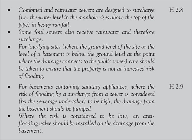
![]() In all such cases, the sewerage undertaker should be consulted to determine the extent and possible frequency of the likely surcharge.
In all such cases, the sewerage undertaker should be consulted to determine the extent and possible frequency of the likely surcharge.
6.4.2.4.3 Pumping installations
p.417
6.4.2.5 Combustion and fuel storage appliances
6.4.2.5.1 LPG storage vessels and appliances
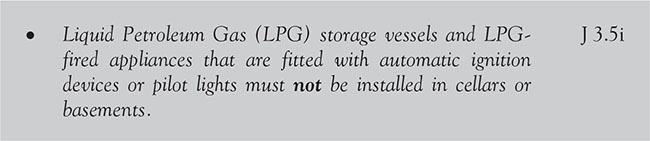
6.4.2.5.2 Location and support of cylinders

6.4.2.6 Protection from falling, collision and impact
Guarding should be provided whenever it is considered necessary from the point of view of safety to guard any basement stair.
6.4.2. 6.1 General provisions

p.418
6.4.2.6.1 Handrails for stairs

6.4.2.6.2 Design of guarding for cellars and basements
Guarding should be provided in accordance with the dimensions in Figure 6.4.3.

Figure 6.4.3 Guarding design

![]() Note: Typical locations for guarding are shown in Figure 6.4.4 and for further guidance on the design of barriers and infill panels refer to BS 6180.
Note: Typical locations for guarding are shown in Figure 6.4.4 and for further guidance on the design of barriers and infill panels refer to BS 6180.
For further guidance on the design of barriers and infill panels, refer to BS 6180.
6.4.2.7 Security
6.4.2.7.1 General
Ground floor, basement and other easily accessible windows (including easily accessible rooflights) should be secure windows in accordance with 6.4.2.7.2.
p.419

Figure 6.4.4 Typical locations for guarding basement or cellar stairs
6.4.2.7.2 Design of secure windows

![]() Note: Further advice is available in Secured by Design’s New Homes 2014.
Note: Further advice is available in Secured by Design’s New Homes 2014.
6.4.2.7.3 Installation and fixing of secure windows

For the purposes of this section, a floor is considered to be the lower horizontal surface of any space in a building and includes finishes that are laid as part of the permanent construction.
p.420

Figure 6.5.1 Typical concrete floor
A floor is an element of structure and should be treated as such.
6.5.1 Requirements

p.421

p.422

p.423

6.5.2 Meeting the requirements
6.5.2.1 Structure
6.5.2.1.1 Basic requirements for stability

6.5.2.1.2 Sizes of certain timber members in floors for dwellings

Softwood timber used for roof construction or fixed in the roof space (including ceiling joists within the void spaces of the roof), should be adequately treated to prevent infestation by the house longhorn beetle (Hylotrupes bajulus). Figure 6.5.2 shows the house longhorn beetle.


Figure 6.5.2 The house longhorn beetle
![]() Note: Guidance on suitable preservative treatments is given in www.woodworm-info.co.uk/house_longhorn_google.htm?gclid=CIeN2uS91tECFYsy0wodCvQCeA.
Note: Guidance on suitable preservative treatments is given in www.woodworm-info.co.uk/house_longhorn_google.htm?gclid=CIeN2uS91tECFYsy0wodCvQCeA.
6.5.2.1.3 Maximum floor area
As shown in Figure 6.5.3:


p.424

Figure 6.5.3 Maximum floor area

Figure 6.5.4 Maximum span of floors
6.5.2.1.4 Lateral support by roofs and floors

p.425


Figure 6.5.5 Lateral support by floors

p.426
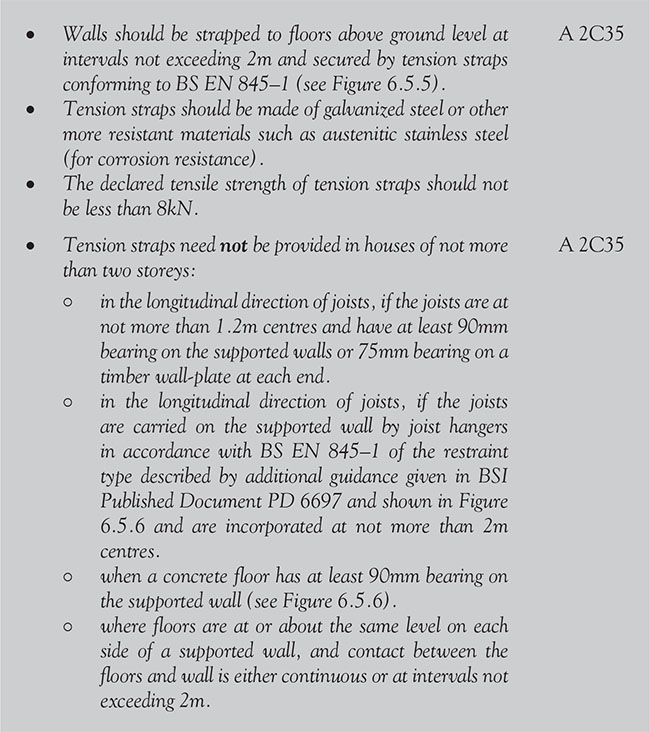

Figure 6.5.6 Restraint type joist hanger and restraint by concrete floor
p.427


Figure 6.5.7 Restraint of internal walls
6.5.2.1.5 Interruption of lateral support

6.5.2.1.6 Disproportionate collapse
It is important to reduce the sensitivity of the building to disproportionate collapse in the event of an accident, especially:
• single-occupancy houses
• flats, apartments and other residential buildings not exceeding four storeys
• all buildings not exceeding two storeys to which members of the public are admitted and which contain floor areas not exceeding 2000m² at each storey.
p.428


Figure 6.5.8 Area at risk of collapse in the event of an accident
whichever is smaller, and should not extend further than the immediate adjacent storeys (see Figure 6.5.8). A 5.1
6.5.2.2 Fire safety
6.5.2.2.1 Material alterations

p.429

6.5.2.2.2 Means of escape
It is important that people can exit from the dwelling safely.
6.5.2.2.2.1 provisions for escape from upper floors not more than 4.5 m above ground level

6.5.2.2.2.2 fire safety – provisions for escape from upper floors more than 4.5 m above ground level

6.5.2.2.3 Fire spread

![]() Note: A ceiling suspended below a floor will contributes to the fire resistance of the floor.
Note: A ceiling suspended below a floor will contributes to the fire resistance of the floor.

Figure 6.5.9 Means of escape from a dwelling
Table 6.5.1 Specific provisions of test for fire resistance of elements of structure – floors
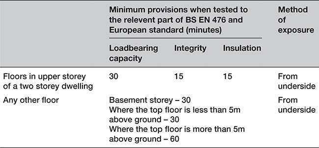
p.430
6.5.2.2.4 Loadbearing elements of structure

6.5.2.2.5 Compartmentation

p.431
6.5.2.2.6 Concealed spaces
Concealed spaces or cavities in the construction of a building provide a ready route for smoke and flame spread e.g. in walls, floors, ceilings and roofs.

6.5.2.2.7 Openings for pipes

p.432

Figure 6.5.10 Enclosure for drainage or water pipes

Figure 6.5.11 Flues penetrating compartment walls or floors
Table 6.5.2 Limitations on fire-protecting suspended ceilings

![]() Note: In some circumstances roofs, or parts of roofs, may need to be fire-resisting, e.g. if used as an escape route or if the roof performs the function of a floor.
Note: In some circumstances roofs, or parts of roofs, may need to be fire-resisting, e.g. if used as an escape route or if the roof performs the function of a floor.
p.433
6.5.2.2.8 Cavities in floor voids

6.5.2.3 Site preparation and resistance to moisture
6.5.2.3.1 Performance

6.5.2.3.2 Flood risk

![]() Note: Further information on flood-resistant and resilient construction can be found in the publication Improving the Flood Performance of New Buildings – Flood Resilient Construction (see www.gov.uk/government/uploads/system/uploads/attachment_data/file/7730/flood_performance.pdf).
Note: Further information on flood-resistant and resilient construction can be found in the publication Improving the Flood Performance of New Buildings – Flood Resilient Construction (see www.gov.uk/government/uploads/system/uploads/attachment_data/file/7730/flood_performance.pdf).
p.434
6.5.2.3.3 Clearance of unsuitable material and resistance to contaminants

![]() Note: BRE Special Digest SD133 provides guidance on investigation, concrete specification and design to mitigate the effects of sulphate attack.
Note: BRE Special Digest SD133 provides guidance on investigation, concrete specification and design to mitigate the effects of sulphate attack.

Figure 6.5.12 Shrinkable clays and sulphate-bearing strata in England and Wales
p.435
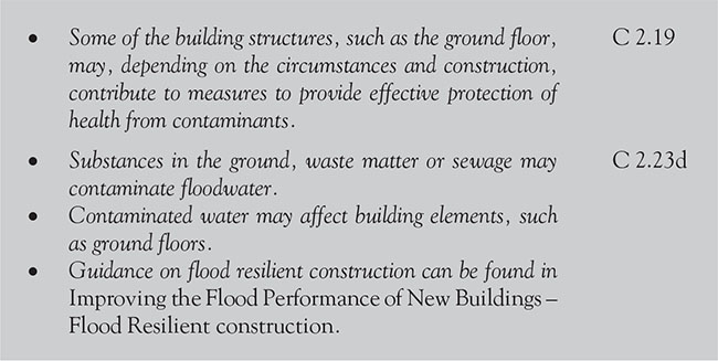
6.5.2.3.4 Remedial measures

6.5.2.3.5 Subsoil drainage

6.5.2.3.6 Role of floors

p.436

6.5.2.3.7 Ground supported floors – moisture from the ground
The damp-proof course should be continuous with any damp-proof membrane in the walls where there is a risk of moisture from the ground.
Some schools of thought believe that there is a need for an additional damp-proof membrane on top of the insulation to combat interstitial condensation. This, however, raises the question: ‘How can this moisture escape?’ Moisture would, presumably, just sit where it is generated and, if interstitial moisture is not controlled by a vapour membrane, it will surely eventually migrate into the concrete or the insulation!
These points have been put to the Department for Communities and Local Government (DCLG), but unfortunately it has been unable to offer any definite answer – responding only that ‘the intention of Approved Documents is to provide guidance to the more common building situations and, as there may be alternative ways of achieving compliance with the requirements, there is no obligation to adopt any particular solution contained in an Approved Document if the builder prefers to meet the relevant requirement in some other way’.

Figure 6.5.13 Ground supported floor – construction (damp-proof courses)
![]() One of our readers has said that he prefers to employ the insulation below the slab and place a damp-proof membrane between the insulation and the blinding wherever possible (if only for ease of construction), which sounds like a very logical solution.
One of our readers has said that he prefers to employ the insulation below the slab and place a damp-proof membrane between the insulation and the blinding wherever possible (if only for ease of construction), which sounds like a very logical solution.

p.437

![]() Note: The requirement can also be achieved by following the relevant recommendations of BS 8102, which also includes recommendations for floors subject to water pressure.
Note: The requirement can also be achieved by following the relevant recommendations of BS 8102, which also includes recommendations for floors subject to water pressure.
6.5.2.3.8 Suspended timber ground floors exposed to moisture from the ground

p.438

p.439

Figure 6.5.14 Suspended timber floor – construction
To prevent water collecting on the ground covering, either the top should be entirely above the highest level of the adjoining ground or, on sloping sites, consideration should be given to installing drainage on the outside of the upslope side of the building (see Figure 6.5.15).

Figure 6.5.15 Suspended floor – preventing water collection
6.5.2.3.9 Suspended concrete ground floors exposed to moisture from the ground

p.440

6.5.2.3.10 Ground floors and floors exposed from below (resistance to damage from interstitial condensation)


Figure 6.5.16 Typical floors exposed from below
6.5.2.3.11 Floors (resistance to surface condensation and mould growth)

6.5.2.4 Resistance to the passage of sound
6.5.2.4.1 General requirements

Table 6.5.3 Dwellings and flats – performance standards for separating floor

![]() Note: The sound insulation values in Table 6.5.3 include a built-in allowance for ‘measurement uncertainty’, and so, if any of these test values are not met, that particular test will be considered as failed.
Note: The sound insulation values in Table 6.5.3 include a built-in allowance for ‘measurement uncertainty’, and so, if any of these test values are not met, that particular test will be considered as failed.
In these cases, it would be best to seek specialist advice before committing yourself.

Figure 6.5.17 Direct and flanking transmission
6.5.2.4.2 Pre-completion testing

p.441

6.5.2.4.3 Junctions between separating walls and other building elements

6.5.2.4.4 Junctions between floors and walls
![]() Where no guidance is provided you should seek specialist advice.
Where no guidance is provided you should seek specialist advice.
Requirements for the most common junctions between walls and floors are shown in the relevant paragraphs of Approved Document E (Resistance to the passage of sound) as follows:

p.442

Figure 6.5.18 Junction between wall type 1 and timber floor


Figure 6.5.19 Junction between wall type 2 and internal timber floor
p.443
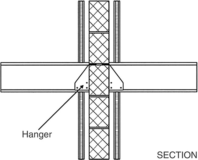
Figure 6.5.20 Junction between wall type 3 and internal timber floor


Figure 6.5.21 Junction between floor type 3 and wall type 1
p.444

Figure 6.5.22 Junction between floor type 3 and wall type 2
6.5.2.4.5 Wall type 1 – solid masonry

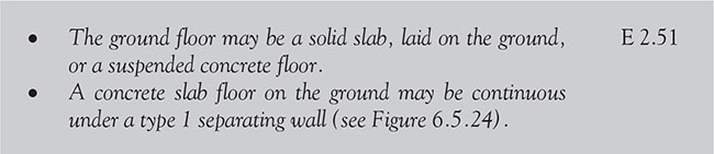
p.445


Figure 6.5.23 Junction between wall type 1 and an internal concrete

Figure 6.5.24 Junction between wall type 1 and a concrete ground floor
p.446
6.5.2.4.6 Wall type 2 – cavity masonry

6.5.2.4.7 Wall type 3 – masonry between independent panels

p.447

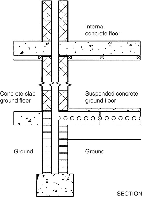
Figure 6.5.25 Junction between wall type 2 and an internal concrete floor/ground floor
p.448

6.5.2.4.8 Wall type 4 – framed walls with absorbent material

p.449

![]() Note:
Note:
1. Where any building element functions as a separating element (e.g. a ground floor that is also a separating floor for a basement flat) then the separating element requirements should take precedence.
2. In some circumstances (e.g. when a historic building is undergoing a material change of use) it may not be practical to improve the sound insulation to the standards set out in the Approved Document, particularly if the special characteristics of such a building need to be recognized. In these circumstances, the aim should be to improve sound insulation to the ‘extent that it is practically possible’.
3. BS 7913 provides guidance on the principles that should be applied when proposing work on historic buildings.

Figure 6.5.26 Junction between wall type 3 and internal concrete floors
6.5.2.4.9 Separating floors and associated flanking constructions for new buildings
There are three types of separating floor, as shown below:
Table 6.5.4 Types of separating floor

6.5.2.4.9.1 ceiling treatments
Each floor type should use one of the following three ceiling treatments, which are ranked in order of sound insulation performance from A to C, as shown in Table 6.5.5 below.
Table 6.5.5 Types of ceiling treatment


p.450

![]() Note: For beam and block separating floors, seek advice from the manufacturer.
Note: For beam and block separating floors, seek advice from the manufacturer.

p.451
![]() Note: The mass per unit area of a floating screed should not be included in the calculation of the mass per unit area of the floor.
Note: The mass per unit area of a floating screed should not be included in the calculation of the mass per unit area of the floor.

![]() Note:
Note:
1. Use of a better performing ceiling than that described in the guidance should improve the sound insulation of the floor, provided there is no significant flanking transmission.
2. Electrical cables give off heat when in use, and special precautions may be required when they are covered by thermal insulating materials.
3. Installing recessed light fittings in ceiling treatments A to C can reduce their resistance to the passage of airborne and impact sound.
6.5.2.4.9.2 floor type 1 – concrete base with ceiling and soft floor covering
A floor of type 1 consists of a concrete floor base with a soft floor covering and a ceiling. Its resistance to airborne sound mainly depends on:
• the mass per unit area of the concrete base
• the mass per unit area of the ceiling
• the soft floor covering (which helps to reduce the source of the impact sound).
The following floor types are appropriate. Details of how junctions are to be made are also described.
Table 6.5.6 Floor type 1 details


p.452

![]() Note: See BS EN ISO 140–8 for details of how to measure the sound insulation in buildings and of building elements
Note: See BS EN ISO 140–8 for details of how to measure the sound insulation in buildings and of building elements
p.453
6.5.2.4.9.2.1 Junction requirements for floor type 1


Figure 6.5.27 Junctions with an external cavity wall with masonry inner leaf
p.454

6.5.2.4.9.2.2 Junctions with floor penetrations (excluding gas pipes)
Pipes and ducts should be in an enclosure (both above and below the floor). In all cases:

6.5.2.4.9.2.3 Junctions with a separating wall type 1
For floor types 1.1C and 1.2C, two possibilities exist.

p.455

Figure 6.5.28 Floor type 1 – floor penetrations
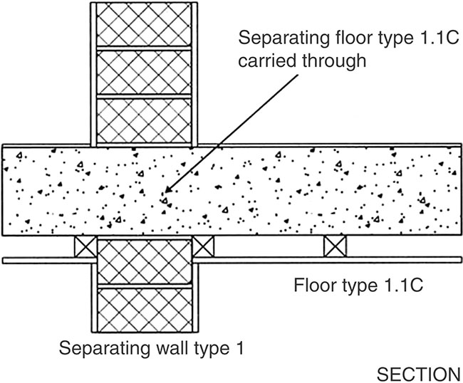
Figure 6.5.29 Floor type 1.1C – wall type 1
p.456


Figure 6.5.30 Floor type 1.2B – wall type 1
![]() It should be noted that for both types of floor, the base (excluding any screed) should not pass through a separating wall type 1, but there are no restrictions on internal walls meeting a type 1 separating floor.
It should be noted that for both types of floor, the base (excluding any screed) should not pass through a separating wall type 1, but there are no restrictions on internal walls meeting a type 1 separating floor.
6.5.2.4.9.2.4 Junctions with a separating wall type 2

p.457

Figure 6.5.31 Floor types 1.1C and 1.2B – wall type 2

6.5.2.4.9.2.5 Junctions with separating wall type 3


Figure 6.5.32 Floor type 1.1C – wall types 3.1 and 3.2
![]() At the time of publication, there is no official guidance available on junctions with a separating wall type 4 and so it would be advisable to seek specialist advice for this type of situation.
At the time of publication, there is no official guidance available on junctions with a separating wall type 4 and so it would be advisable to seek specialist advice for this type of situation.
6.5.2.4.9.3 floor type 2 – concrete base with ceiling and floating floor
A floor of type 2 consists of a concrete floor base with a floating floor (which in turn consists of a floating layer and a resilient layer) and a ceiling. Its resistance to airborne and impact sound depends on:
p.458
• the mass per unit area of the concrete base
• the mass per unit area and isolation of the floating layer and the ceiling
• the floating floor (which reduces impact sound at source).
![]() Note: Two floor types (consisting of a floating layer and resilient layer – see below) will meet these requirements. A performance-based approach (type C) is also available, as shown in Table 6.5.7.
Note: Two floor types (consisting of a floating layer and resilient layer – see below) will meet these requirements. A performance-based approach (type C) is also available, as shown in Table 6.5.7.

Note: For floating floor type C, the floors should have a rigid boarding above a resilient and/or damping layer with a-weighted reduction in impact sound pressure level of not less than 29 dB (see BS EN ISO 717–2 and BS EN ISO 140–8).

p.459
Table 6.5.7 Floating floors

Table 6.5.8 Floor type 2


p.460

Figure 6.5.33 Floor type 2 – external cavity walls with masonry internal leaf
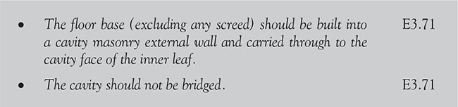
p.461

6.5.2.4.9.3.2 Junctions with floor penetrations (excluding gas pipes)

Figure 6.5.34 Floor type 2 – floor penetrations
p.462

6.5.2.4.9.3.3 Junctions with a separating wall type 1


6.5.2.4.9.3.4 Junctions with a separating wall type 2


Figure 6.5.35 Floor type 2.1C – wall types 3.1 and 3.2
p.463
6.5.2.4.10.3.5 Junctions with separating wall types 3


p.464

Figure 6.5.36 Floor type 2.1C – wall types 3.1 and 3.2
![]() At the time of publication, there is no official guidance available on junctions with a separating wall type 4 and so it would be advisable to seek specialist advice for this type of situation.
At the time of publication, there is no official guidance available on junctions with a separating wall type 4 and so it would be advisable to seek specialist advice for this type of situation.
6.5.2.4.9.4. floor type 3 – timber-frame base with ceiling and platform floor
A floor of type 3 consists of a timber-frame structural floor base with a deck, platform floor (consisting of a floating layer and a resilient layer) and ceiling treatment. Its resistance to airborne and impact sound depends on:
• the structural floor base
• the isolation of the platform floor and the ceiling
• the platform floor (which reduces impact sound at source).

p.465

Table 6.5.9 Floor type 3.1A requirements


6.5.2.4.9.4.1 Junctions with an external cavity wall with masonry inner leaf

p.466

![]() Note:
Note:
1. Any normal method of connecting floor base to wall may be used.
2. Independent panels are not required if the mass per unit area of the inner leaf is greater than 375kg/m2.
6.5.2.4.9.4.2 Junctions with an external cavity wall with timber-frame inner leaf

6.5.2.4.9.4.3 Junctions with internal framed walls

![]() Currently there is no official guidance available on junctions with an external solid masonry walls or internal masonry walls, so it would be best to seek specialist advice in these situations.
Currently there is no official guidance available on junctions with an external solid masonry walls or internal masonry walls, so it would be best to seek specialist advice in these situations.
6.5.2.4.9.4.4 Junctions with floor penetrations (excluding gas pipes)

Figure 6.5.37 Floor type 3 – floor penetrations

p.467

![]() Note: Independent panels are not required if the mass per unit area of the inner leaf is greater than 375kg/m2.
Note: Independent panels are not required if the mass per unit area of the inner leaf is greater than 375kg/m2.
6.5.2.4.9.4.5 Junctions with a separating wall type 3 – masonry between independent panels

6.5.2.4.9.4.6 Junctions with a separating wall type 4 – timber frames with absorbent material

p.468
6.5.2.4.10 Dwelling-houses and flats formed by material change of use

p.469

6.5.2.4.10.1 floor treatment 1: independent ceiling with absorbent material

p.470

![]() Note: This construction involves a separation of at least 125mm between the upper surface of the independent ceiling and the underside of the existing floor construction. However, structural considerations determining the size of ceiling joists will often result in greater separation. Care should be taken at the design stage to ensure that adequate ceiling height is available in all rooms to be treated.
Note: This construction involves a separation of at least 125mm between the upper surface of the independent ceiling and the underside of the existing floor construction. However, structural considerations determining the size of ceiling joists will often result in greater separation. Care should be taken at the design stage to ensure that adequate ceiling height is available in all rooms to be treated.

Figure 6.5.38 Floor Treatment 1 – Dwellings formed by a material change of use
p.471


Figure 6.5.39 Floor Treatment 1 – high window detail - dwellings formed by a material change of use

p.472

Figure 6.5.40 Floor Treatment 1 – wall treatment 1 - dwellings formed by a material change of use
6.5.2.4.10.2 floor treatment 2: platform floor with absorbent material

p.473

![]() Note: The lower figure of density for the resilient layer gives the best insulation but a ‘softer’ floor. In such cases, additional support can be provided around the perimeter of the floor by using a timber batten with a foam strip along the top attached to the wall.
Note: The lower figure of density for the resilient layer gives the best insulation but a ‘softer’ floor. In such cases, additional support can be provided around the perimeter of the floor by using a timber batten with a foam strip along the top attached to the wall.

Figure 6.5.41 Floor Treatment 2 - dwellings formed by a material change of use
p.474

![]() Remember that stairs are subject to the same sound insulation requirements as floors where they perform a separating function.
Remember that stairs are subject to the same sound insulation requirements as floors where they perform a separating function.

Figure 6.5.42 Floor treatment 2 – wall treatment 1 - dwellings formed by a material change of use
p.475

6.5.2.4.10.3 junctions with floor penetrations

![]() Note: There are requirements for ventilation of ducts at each floor where they contain gas pipes. Gas pipes may be contained in a separate ventilated duct or they can remain unducted. Where a gas service is installed, it should comply with relevant codes and standards to ensure safe and satisfactory operation (also see the Gas Safety (Installation and Use) Regulations 1998, SI 1998/24).
Note: There are requirements for ventilation of ducts at each floor where they contain gas pipes. Gas pipes may be contained in a separate ventilated duct or they can remain unducted. Where a gas service is installed, it should comply with relevant codes and standards to ensure safe and satisfactory operation (also see the Gas Safety (Installation and Use) Regulations 1998, SI 1998/24).
p.476

Figure 6.5.43 Floor penetrations – dwellings formed by a material change of use
6.5.2.4.11 Internal walls and floors in new buildings


p.477

Guidance on layout is provided in BS 8233 which provides guidance on sound insulation and noise reduction for buildings.

![]() Note: Insulation against impact sounds can be improved by adding a soft covering (e.g. carpet).
Note: Insulation against impact sounds can be improved by adding a soft covering (e.g. carpet).

Figure 6.5.44 Internal floor type A – dwellings formed by a material change of use

![]() Note: Insulation against impact sounds can be improved by adding a soft covering (e.g. carpet).
Note: Insulation against impact sounds can be improved by adding a soft covering (e.g. carpet).
p.478

Figure 6.5.45 Internal floor type B - dwellings formed by a material change of use

![]() Note: Insulation against impact sounds can be improved by adding a soft covering (e.g. carpet).
Note: Insulation against impact sounds can be improved by adding a soft covering (e.g. carpet).
Electrical cables give off heat when in use and special precautions may be required when they are covered by thermally insulating materials (See BRE BR 262, Thermal Insulation: Avoiding risks, Section 2.4).

Figure 6.5.46 Internal floor type C – dwellings formed by a material change of use
6.5.2.5 Ventilation
Extensions of buildings at ground level with a floor area less than 30m2 by the addition of a conservatory, porch, covered yard, covered way, or carport open on at least two sides do not have to comply with Approved Document F (Ventilation).
p.479
6.5.2.5.1 Air transfer

6.5.2.6 Sanitation, hot water safety and water efficiency
6.5.2.6.1 Branch discharge pipes

p.480
6.5.2.6.2 Pumping installations

6.5.2.6.3 Enclosures and storage areas

6.5.2.7 Combustion appliances and fuel storage systems

![]() Note: BRE Report BR 414 (2001) and BRE Report BR 211 (2007) give guidance on penetration of membranes.
Note: BRE Report BR 414 (2001) and BRE Report BR 211 (2007) give guidance on penetration of membranes.
p.481


Figure 6.5.47 Air vent openings in a solid floor
6.5.2.7.1 Location and shielding of connecting fluepipes

p.482

![]() Note: A way of achieving this would be to provide a change in level.
Note: A way of achieving this would be to provide a change in level.

6.5.2.7.2 Hearths for oil-fired appliances

6.5.2.8 Protection from falling, collision and impact

![]() Note: A floor level with a gradient of 1:20 or steeper should be designed as a ramp.
Note: A floor level with a gradient of 1:20 or steeper should be designed as a ramp.
p.483
6.5.2.9 Conservation of fuel and power
If work is being undertaken on an existing building which has a total useful floor area of over 1000m2, then, in addition to the principal works (which must still comply with the energy efficiency requirements detailed in Approved Document L (Conservation of fuel and power), in the normal way), consequential improvements, where technically, functionally and economically feasible, will also have to be completed.

Table 6.5.10 Upgrading retained thermal elements

In addition, the standards for new thermal elements should be no worse than those shown in Table 6.5.11.
Table 6.5.11 Upgrading required for new thermal elements

When undertaking renovation works to thermal elements you should consider the cost effectiveness of achieving the U-value targets. In the case of floors:
• the renovation of a solid floor could be through the replacement of screed with an insulated floor deck to maintain the existing floor level
• in a suspended timber floor, the fitting of insulation between floor joists prior to the replacement of the floor deck is recommended.
p.484
![]() Note: The cost effectiveness of this work is complicated by the size and shape of the floor. In many cases, an uninsulated floor has relatively low U-values in comparison to wall and roofs. It is likely therefore that the addition of insulation is only cost effective where the existing floor U-value is greater than 0.70W/m2K.
Note: The cost effectiveness of this work is complicated by the size and shape of the floor. In many cases, an uninsulated floor has relatively low U-values in comparison to wall and roofs. It is likely therefore that the addition of insulation is only cost effective where the existing floor U-value is greater than 0.70W/m2K.
6.5.2.10 Access to and use of buildings
6.5.2.10.1 Communal entrances

6.5.2.9.2 Through-floor lifting device provision

![]() Note: Approved Document M is an optional requirement for wheelchair user dwellings.
Note: Approved Document M is an optional requirement for wheelchair user dwellings.
p.485
In a brick-built house, the external walls are loadbearing elements that support the roof, floors and internal walls. These walls are normally cavity walls comprising two leaves braced with metal ties, but older houses will have solid walls, at least 225mm thick. Bricks are laid with mortar in overlapping bonding patterns to give the wall rigidity and a damp-proof course is laid just above ground level to prevent the moisture rising. Window and door openings are spanned above with rigid supporting beams called lintels and the internal walls are either non-loadbearing divisions made from lightweight blocks, manufactured boards or timber studding, or loadbearing structures made of brick or block.
Modern timber-framed house walls, on the other hand, are constructed of vertical timber studs with horizontal top and bottom plates nailed to them. The frames, which are erected either on a concrete slab or a suspended timber platform supported by cavity brick walls, are faced on the outside with plywood sheathing to stiffen the structure. Breather paper is fixed over the top to act as a moisture barrier. Insulation quilt is used between studs. Rigid timber lintels at openings carry the weight of the upper floor and roof. Brick cladding is typically used to cover the exterior of the frame and is attached to the frame with metal ties. Weatherboarding often replaces the brick cladding on upper floors.
p.486

Figure 6.6.1 Brick-built house – typical components

Figure 6.6.2 Timber-framed house – typical components
p.487
For the purposes of this section (and the various Approved Documents) a wall includes:
• the surface of glazing (except glazing in doors); and
• any part of a ceiling which slopes at an angle of more than 70° to the horizontal.
A wall does not include:
• doors and door frames
• window frames and frames in which glazing is fitted
• architraves, cover moulds, picture rails, skirtings and similar narrow members;
• fireplace surrounds, mantle shelves and fitted furniture.
![]() A wall common to two or more buildings shall be designed and constructed so that it adequately resists the spread of fire between those buildings. A house in a terrace and a semi-detached house are treated as separate buildings.
A wall common to two or more buildings shall be designed and constructed so that it adequately resists the spread of fire between those buildings. A house in a terrace and a semi-detached house are treated as separate buildings.
![]() Note: When reading this section, you will probably notice that a few of the requirements are also covered in sections 6.5 (Floors) and 6.7 (Ceilings). This has been done in order to save the reader having to constantly turn back and reread a previous page!
Note: When reading this section, you will probably notice that a few of the requirements are also covered in sections 6.5 (Floors) and 6.7 (Ceilings). This has been done in order to save the reader having to constantly turn back and reread a previous page!
6.6.1 Requirements

p.488

p.489

p.490

p.491
6.6.2 Meeting the requirements
6.6.2.1 Structure
6.6.2.1.1 General
Walls should comply with the relevant requirements of BS EN 1996–2 but also see BS EN 1996–1-1+A1 if design strengths (and suitability) of walls using masonry units with different compressive strengths are being considered.
![]() Approved Document A assumes that no floor enclosed by structural walls on all sides exceeds 70m2, and that no floor without a structural wall on one side exceeds 36m2. If you require guidance relating to site exposure conditions and wind speeds, this is available in Approved Document A (Structure) (Table C of Diagram 7) and is included in Chapter 6.1 of this book.
Approved Document A assumes that no floor enclosed by structural walls on all sides exceeds 70m2, and that no floor without a structural wall on one side exceeds 36m2. If you require guidance relating to site exposure conditions and wind speeds, this is available in Approved Document A (Structure) (Table C of Diagram 7) and is included in Chapter 6.1 of this book.
6.6.2.1.2 Basic requirements for stability
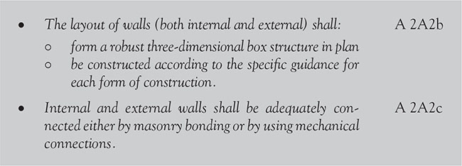
6.2.2.1.3 Thickness of walls in certain small buildings
This section applies to the following building types:
• residential buildings of not more than three storeys
• small single-storey non-residential buildings
• small buildings forming annexes to residential buildings (including garages and outbuildings).

p.492
Table 6.6.1 Wall types

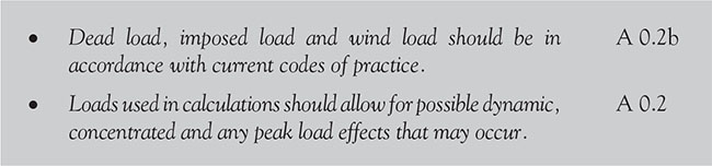
6.6.2.1.3.1 dimensions of walls
The thickness of the wall depends on the general conditions relating to the building of which the wall forms a part (e.g. floor area, roof loading, wind speed, etc.) and the design conditions relating to the wall (e.g. type of materials, loading, end restraints, openings, recesses, overhangs, lateral floor support requirements, etc.).
![]() Note: Where walls are constructed of bricks or blocks, they shall be in accordance with BS EN 1991–1-4+A1
Note: Where walls are constructed of bricks or blocks, they shall be in accordance with BS EN 1991–1-4+A1
The recommended thicknesses of different types of walls are given below:
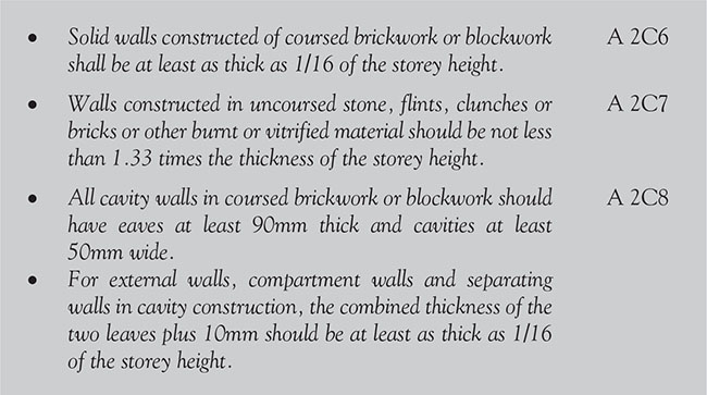

Table 6.6.2 Minimum thickness of certain external walls, compartment walls and separating walls


![]() Note: Except for a wall in the lowest storey of a three-storey building that carries the load from both upper storeys, walls should have a thickness as determined by the equation in A2C10 (above) or 140mm, whichever is the greater.
Note: Except for a wall in the lowest storey of a three-storey building that carries the load from both upper storeys, walls should have a thickness as determined by the equation in A2C10 (above) or 140mm, whichever is the greater.
p.493

Figure 6.6.3 Height of parapet walls
6.6.2.1.3.2 small building dimensions


p.494

Figure 6.6.4 Maximum height of buildings
p.495

Figure 6.6.5 Residential buildings not more than three storeys
6.6.2.1.3.3 wall ties
There are two types of wall tie that can be used in masonry cavity walls:
• type A (butterfly ties), which are normal
• type B (double-triangle ties), which are used only in external masonry cavity walls where tie type A does not satisfy the requirements of Approved Document A (Structure).
![]() Note:
Note:
1. The recommended cavity widths in separating cavity masonry walls are minimum values.
2. In external cavity masonry walls, tie type B may decrease the airborne sound insulation due to flanking transmission via the external wall leaf compared to tie type A.
3. Stainless steel cavity wall ties are specified for all houses regardless of their location.
6.6.2.1.3.4 cavity walls in coursed brickwork or blockwork

p.496
Table 6.6.3 Cavity wall ties


![]() Note:
Note:
1. Where face-insulated blocks are used, the cavity width should be measured from the face of the masonry unit.
2. The embedment depth of the tie should not be less than 50mm in both leaves.
3. For cavities wider than 175mm calculate the length as the nominal cavity width plus 125mm and select the nearest stock length. For wall ties requiring embedment depths in excess of 50mm, increase the calculated tie length accordingly.
6.6.2.1.3.5 masonry units – construction and workmanship
Walls should be properly bonded and solidly put together with mortar and constructed of masonry units conforming to the following standards:

p.497
6.6.2.1.3.6 mortar
Mortar should be one of the following:

6.6.2.1.3.7 loading on walls


Figure 6.6.6 Maximum span of floors

p.498


Figure 6.6.7 Combined and imposed dead load
6.6.2.1.3.8 end restraint
6.6.2.1.3.8.1 Vertical lateral restraint to walls

![]() Note: Each distinct length is considered to be a supported wall for the purposes of the Building Regulations.
Note: Each distinct length is considered to be a supported wall for the purposes of the Building Regulations.

p.499
6.6.2.1.3.8.2 Buttressing walls
If the buttressing wall is not itself a supported wall, its thickness T2 should not be less than:

The length of the buttressing wall should be:


Figure 6.6.8 Openings in a buttressing wall
p.500
6.6.2.1.3.8.3 Piers and chimneys providing restrain
The sectional area on plan of chimneys (excluding openings for fireplaces and flues) should be not less than the area required for a pier in the same wall. The overall thickness should not be less than twice the required thickness of the supported wall (Figure 6.6.9).


Figure 6.6.9 Buttressing
p.501
6.6.2.1.3.8.4 Openings, recesses, overhangs and chases
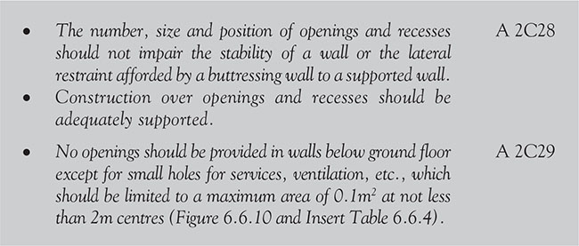

Figure 6.6.10 Sizes of openings and recesses
6.6.2.1.3.8.5 Chases

p.502
Table 6.6.4 Value of X factor for Figure 6.6.10

![]() Note: Or, in cavity walls, 1/3 of the thickness of the leaf of the wall.
Note: Or, in cavity walls, 1/3 of the thickness of the leaf of the wall.

6.6.2.1.3.8.6 Overhangs

6.6.2.1.3.9 lateral support by roofs and floors

p.503
Table 6.6.5 Lateral support for walls

6.6.2.1.3.9.1 Tension straps


Figure 6.6.11 Lateral support by floors

p.504


Figure 6.6.12 Restraint type joist hanger

Figure 6.6.13 Restraint by concrete floor or roof
p.505


Figure 6.6.14 Restraint of internal walls

Figure 6.6.15 Lateral support at roof level
6.6.2.1.3.9.2 Gable wall tension straps

p.506

6.6.2.1.4 Wall cladding
Wall cladding presents a hazard if it becomes detached from the building. An acceptable level of safety can be achieved depending on the type and location of the cladding.
![]() Following the Grenfell Tower blaze the UK government launched an independent review of building regulations after tests showed that at least 82 residential high-rises use a combination of insulation and cladding that did not meet fire safety standards.
Following the Grenfell Tower blaze the UK government launched an independent review of building regulations after tests showed that at least 82 residential high-rises use a combination of insulation and cladding that did not meet fire safety standards.

![]() Note: Guidance on funnelling effects is given in BRE Digest 436, Wind Loading on Buildings: Brief Guidance for Using BS 6399–2.
Note: Guidance on funnelling effects is given in BRE Digest 436, Wind Loading on Buildings: Brief Guidance for Using BS 6399–2.

p.507

![]() Note: Large glass panels in cladding of walls and roofs (where the cladding is not divided into small areas by loadbearing framing) need special consideration. Guidance is given in the Institution of Structural Engineers’ report Structural Use of Glass in Buildings, 1999, and Nickel Sulphide in Toughened Glass, published by the Centre for Window Cladding and Technology, 2000.
Note: Large glass panels in cladding of walls and roofs (where the cladding is not divided into small areas by loadbearing framing) need special consideration. Guidance is given in the Institution of Structural Engineers’ report Structural Use of Glass in Buildings, 1999, and Nickel Sulphide in Toughened Glass, published by the Centre for Window Cladding and Technology, 2000.
Further guidance on cladding is also provided in the following documents:
• The Institution of Structural Engineers’ report Aspects of Cladding, 1995
• The Institution of Structural Engineers’ report Guide to the Structural Use of Adhesives, 1999
• BS 8297 Code of Practice for the Design and Installation of Non-Loadbearing Precast Concrete Cladding
• BS 8298–1 Code of Practice for the Design and Installation of Natural Stone Cladding and Lining.
p.508
6.6.2 2 Fire safety
Proprietary fire-stopping and sealing systems (including those designed for service penetrations) that have been shown by test to maintain the fire resistance of the wall or other element are available and may be used. Other fire-stopping materials include:
• cement mortar
• gypsum-based plaster
• cement or gypsum-based vermiculite/perlite mixes
• glass fibre, crushed rock, blast furnace slag or ceramic-based products (with or without resin binders)
• intumescent (acrylic) mastics.
6.6.2.2.1 Smoke alarms
There should be a smoke alarm in the circulation space within 7.5m of the door to every habitable room.

6.6.2.2.2 Air-circulation systems in houses with a floor more than 4.5m above ground level
To avoid the possibility of smoke or fire spreading into a protected stairway:

p.509
6.6.2.2.3 Fire spread and internal linings
The choice of materials for walls and ceilings can significantly affect the spread of a fire and its rate of growth, even though they are not likely to be the materials first ignited. It is particularly important in circulation spaces where linings may offer the main means by which fire spreads and where rapid spread is most likely to prevent occupants from escaping. Several properties of lining materials influence fire spread, such as the ease of ignition and the rate at which the lining material gives off heat when burning.


Figure 6.6.16 Separation between garage and dwelling-house
If a door is provided between a dwelling and the garage:

p.510
![]() Note: Fire doors only need to be provided with self-closing devices if they are between a dwelling and an integral garage.
Note: Fire doors only need to be provided with self-closing devices if they are between a dwelling and an integral garage.
6.6.2.2.3.1 classification of linings
In general terms, the surface linings for walls should meet the classifications given in Table 6.6.6.
Table 6.6.6 Clarification of linings

![]() Further guidance on wall linings are provided in paragraphs 3.2 to 3.14 of Approved Document B (Fire safety) Volume 1.
Further guidance on wall linings are provided in paragraphs 3.2 to 3.14 of Approved Document B (Fire safety) Volume 1.

6.6.2.2.4 Cavities and concealed spaces
Concealed spaces or cavities in walls, floors, ceilings and roofs will provide an easy route for smoke and flame spread which, because it is hidden, will present a greater danger than would be more obvious from a weakness in the fabric of the building. To overcome this danger, buildings shall be designed and constructed so that the unseen spread of fire and smoke within concealed spaces in their structure and fabric is prevented.

![]() Note: With the introduction of the 2013 (amended) Approved Document B, window and door frames are now only suitable for use as cavity barriers if they are constructed of steel or timber of an appropriate thickness.
Note: With the introduction of the 2013 (amended) Approved Document B, window and door frames are now only suitable for use as cavity barriers if they are constructed of steel or timber of an appropriate thickness.
p.511
6.6.2.2.5 Provision of cavity barriers
Cavity barriers should be provided in the following locations:


Figure 6.6.17 Interrupting concealed spaces and cavities. (a, b) Sections. (c, d) Plans
p.512
6.6.2.2.5.1 construction and fixings for cavity barriers

6.6.2.2.5.2 openings in cavity barriers
Openings in a cavity barrier should be limited to the following:

p.513
6.6.2.2.6 Fire resistance and fire-stopping

6.6.2.2.7 Loadbearing elements of structure
‘Elements of structure’ is the term applied to the main structural loadbearing elements, such as structural frames, floors and loadbearing walls. Compartment walls are treated as elements of structure although they are not necessarily loadbearing. External walls, such as curtain walls or other forms of cladding that transmit only self-weight and wind loads and do not transmit floor load are not regarded as loadbearing for the purposes of their resistance to collapse, although they may need fire resistance to satisfy requirement B4.

p.514
Table 6.6.7 Specific provisions of test for fire resistance of elements of structure – walls


p.515
6.6.2.2.8 Compartmentation
The appropriate degree of subdivision depends on:
• the use of and fire load in the building
• the height to the floor of the top storey in the building
• the availability of a sprinkler system.
![]() Note: Adjoining buildings should only be separated by walls, not floors, unless they are fire-resistant.
Note: Adjoining buildings should only be separated by walls, not floors, unless they are fire-resistant.
To prevent the spread of fire within a building, whenever possible:

![]() Note: The lowest floor in a building does not need to be constructed as a compartment floor.
Note: The lowest floor in a building does not need to be constructed as a compartment floor.
6.6.2.2.8.1 junction of compartment wall with roof
If a fire penetrates a roof near a compartment wall, there is a risk that it will spread over the roof to the adjoining compartment. To reduce this risk, the wall should be:

p.516


Figure 6.6.18 Junction of compartment wall with roof
6.6.2.2.8.2 openings in compartment walls separating buildings or occupancies
All other openings in compartment walls or compartment floors should be limited to those for:

6.6.2.2.8.3 flats
In buildings containing flats, the guidance in Volume to of Approved Document B (Fire safety) should be used (see Chapter 7.6)
6.6.2.2.8.4 construction of compartment walls
Note: Adjoining buildings should only be separated by walls, not floors.
p.517

![]() Note: Consideration should also be given to the effect of services that may be built into the construction that could adversely affect its fire resistance. For instance, where downlighters, loudspeakers and other electrical accessories are installed, additional protection may be required to maintain the integrity of a wall or floor.
Note: Consideration should also be given to the effect of services that may be built into the construction that could adversely affect its fire resistance. For instance, where downlighters, loudspeakers and other electrical accessories are installed, additional protection may be required to maintain the integrity of a wall or floor.
6.6.2.2.9 Ventilation ducts and flues, etc.

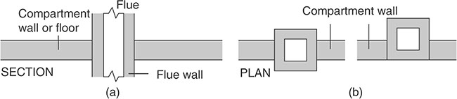
Figure 6.6.19 Flues penetrating compartment walls or floors
p.518
6.6.2.2.10 Construction of an external wall
The external walls of the building shall adequately resist the spread of fire over the walls and from one building to another, having regard to the height, use and position of the building. In addition, the external walls of the building should have sufficient fire resistance to prevent fire spread across the boundary.

Figure 6.6.20 Provisions for external surfaces of walls
(a), (d), (e) Any building
(b) Any building other than (c)
(c) Assembly or recreation building of more than one storey

p.519

6.6.2.2.11 Space separation

p.520


Figure 6.6.21 Relevant boundary
p.521
6.6.2.2.11.1 methods for calculating acceptable unprotected area
6.6.2.2.11.1.1 Method 1
Method 1 may be used for small residential buildings.


Figure 6.6.22 Permitted unprotected areas for Method 1
p.522
![]() Note: In calculating the maximum unprotected area, any areas falling within the limits shown in Figure 6.6.23, which are small unprotected areas in an otherwise protected area of wall, are considered to pose a negligible risk of fire spread and can be disregarded.
Note: In calculating the maximum unprotected area, any areas falling within the limits shown in Figure 6.6.23, which are small unprotected areas in an otherwise protected area of wall, are considered to pose a negligible risk of fire spread and can be disregarded.

Figure 6.6.23 Unprotected areas which may be disregarded in assessing separation distance from the boundary
6.6.2.2.9.1.2 Method 2
Method 2 may be used for most buildings or compartments for which Method 1 is not appropriate.

p.523

Table 6.6.8 Permitted unprotected areas for Method 2

![]() Note: For any building or compartment more than 10m in height, the methods set out in the BRE report External Fire Spread: Building Separation and Boundary Distances can be applied.
Note: For any building or compartment more than 10m in height, the methods set out in the BRE report External Fire Spread: Building Separation and Boundary Distances can be applied.
![]() The boundary formed by the wall separating a pair of semi-detached houses may be disregarded for the purposes of this Section (but see Section 6.6.2.2.8.1, which deals with roofs passing over the top of a compartment wall).
The boundary formed by the wall separating a pair of semi-detached houses may be disregarded for the purposes of this Section (but see Section 6.6.2.2.8.1, which deals with roofs passing over the top of a compartment wall).
6.6.2.2.10 Single-storey buildings
Although most elements of structure in a single-storey building may not need fire resistance, fire resistance will be needed if the element:
• is part of (or supports) an external wall and there is provision to limit the extent of openings and other unprotected areas in the wall; or
• is part of (or supports) a compartment wall, including a wall common to two or more buildings, or a wall between a dwelling and an attached or integral garage; or
• supports a gallery.
p.524
6.6.2.3 Site preparation and resistance to moisture.
The base of walls on any site can be damaged by moisture which can rise from the ground, and much more severe problems can arise in sites that are liable to flooding. Substances in the ground, waste matter or sewage may contaminate floodwater and this contaminated water may affect building elements, such as walls.
Driving rain or wind-driven spray from the sea or other water bodies adjacent to the building can penetrate walls directly, or through cracks or joints between elements, and damage the structure or internal fittings or equipment. Surface condensation from the water vapour generated within the building can cause moulds to grow which pose a health hazard to occupants. Interstitial condensation (a form of structural damping that occurs when warm, moist air penetrates inside a wall, roof or floor structure, reaches the dew point and condenses into liquid water) may damage the structure. Spills and leaks of water, in rooms where sanitary fittings or fixed appliances that use water are installed (e.g. bathrooms and kitchens), may also damage walls.
6.6.2.3.1 Foundations

p.525


Figure 6.6.24 Resistance to moisture.
(a) External wall. (b) Internal wall.
6.6.2.3.2 Resistance to moisture in walls
Walls can be exposed to moisture in four ways:
• internal and external walls exposed to moisture from the ground
• external walls exposed to precipitation from the outside:
• interstitial condensation in any type of wall
• surface condensation or mould growth on any type of wall.
A ‘wall’ includes piers, columns and parapets. It also includes chimneys if they are attached to the building. It does not include windows, doors and similar openings, but does include the joint between their frames and the wall. In the following, the term ‘precipitation’ includes the effects of spray blown from the sea or any other body of water adjacent to the building. All walls should:

p.526
External walls should:

![]() For buildings that are used wholly for storing goods and/or provisions, this requirement may not apply.
For buildings that are used wholly for storing goods and/or provisions, this requirement may not apply.
6.6.2.3.2 Internal and external walls exposed to moisture from the ground


Figure 6.6.25 Damp-proof courses
p.527


Figure 6.6.26 Cavity carried down

p.528

Figure 6.6.27 Damp-proof (cavity) tray
6.6.2.3.3 Solid external walls
![]() Solid walls should be capable of holding moisture arising from rain and snow until it can be released in a dry period without penetrating to the inside of the building or causing damage to the building.
Solid walls should be capable of holding moisture arising from rain and snow until it can be released in a dry period without penetrating to the inside of the building or causing damage to the building.

p.529


Figure 6.6.28 Projection of wall head from precipitation

p.530


Figure 6.6.29 Insulated (solid) external wall
6.6.2.3.4 Cavity external walls
The outer leaf of cavity external walls shall be separated from the inner leaf by a drained air space (or in any other way which will prevent precipitation from being carried to the inner leaf).
p.531


Figure 6.6.30 Masonry cavity walls excluded from the previous for cavity barriers
p.532
Table 6.6.9 Maximum recommended exposure zones for insulated masonry walls

p.533
Table 6.6.9 Maximum recommended exposure zones for insulated masonry walls (Continued)
p.534

6.6.2.3.5 Framed external walls


Figure 6.6.31 Insulated framed wall
p.535
It should be noted that the use of combustible materials for cladding framework, or the use of combustible thermal insulation as an over-cladding may be risky in tall buildings, even though the provisions for external surfaces in Figure 6.6.31 may have been satisfied.
Combustible materials should not be placed in or exposed to the cavity, except for:
• timber lintels, window or door frames, or the end stairway of timber joists
• pipes, conduits or cables
• damp-proof course, flashing, cavity closer or wall ties
• fire-resisting thermal insulating material
• a domestic meter cupboard.
6.6.2.3.6 Cracking of external walls
Cladding can be designed to protect a building from precipitation (often driven by the wind) either by holding it at the face of the building or by stopping it from penetrating beyond the back of the cladding.
![]() The possibility of severe rain penetrating through cracks in masonry external walls should be taken into account when designing a building.
The possibility of severe rain penetrating through cracks in masonry external walls should be taken into account when designing a building.
6.6.2.3.7 Impervious cladding systems for walls
Cladding systems for walls should:

p.536

![]() Note: Whether dry joints are suitable will depend on the design of the joint or the design of the cladding and the severity of the exposure to wind and rain.
Note: Whether dry joints are suitable will depend on the design of the joint or the design of the cladding and the severity of the exposure to wind and rain.

p.537

6.6.2.3.8 Joints between walls and doors/window frames

6.6.2.3.9 Interstitial condensation (external walls)

p.538

Figure 6.6.32 Window reveals for use in areas subject to very severe driving rain
![]() Specialist advice should be sought when designing swimming pools and other buildings where interstitial condensation in the walls (caused by high internal temperatures and humidity) can cause the generation of high levels of moisture.
Specialist advice should be sought when designing swimming pools and other buildings where interstitial condensation in the walls (caused by high internal temperatures and humidity) can cause the generation of high levels of moisture.
6.6.2.3.10 Surface condensation and mould growth (external walls)
External walls shall be designed and constructed so that:

6.2.4 Cavity insulation
Insulating materials which give off formaldehyde fumes (either when used or later in normal use) may be used to insulate the cavity in a cavity wall where there is a continuous barrier which will minimize as far as practicable the passage of fumes to the occupiable parts. A cavity wall may be insulated with urea formaldehyde (UF) foam where:
p.539

6.6.2.5 Resistance to the passage of sound
6.6.2.5.1 Airborne sound
• The flow of sound energy through walls should be restricted.
• Walls should reduce the level of airborne sound.
• Walls that separate a dwelling from another building (or another dwelling) shall resist the transmission of airborne sound.
• Habitable rooms (or kitchens) within a dwelling shall resist the transmission of airborne sound.
• Air paths, including those due to shrinkage, must be avoided.
• Porous materials and gaps at joints in the structure must be sealed.
• Flanking transmission (i.e. the indirect transmission of sound from one side of a wall to the other side) should be minimized.
• The possibility of resonance in parts of the structure (such as a dry lining) should be avoided.
6.6.2.5.2 Performance

p.540

Figure 6.6.33 Direct and flanking transmission
Table 6.6.10 Dwellings and flats – performance standards for walls that have a separating function

![]() Note:
Note:
1. The sound insulation values in Table 6.6.10 include a built-in allowance for ‘measurement uncertainty’ and so, if any of these test values are not met, that particular test will be considered as failed.
2. Occasionally, a higher standard of sound insulation may be required between spaces used for normal domestic purposes and noise generated in and to an adjoining communal or non-domestic space.
p.541
![]() In cases like these, it would be best to seek specialist advice before committing yourself.
In cases like these, it would be best to seek specialist advice before committing yourself.
Figure 6.6.34 illustrates the relevant parts of the building that should be protected from airborne and impact sound in order to satisfy the requirement.

Figure 6.6.34 Requirement E1 – resistance to sound
Figure 6.6.35 illustrates the relevant parts of the building that should be protected from airborne and impact sound in order to satisfy Requirement E2a.

Figure 6.6.35 Requirement E2a – internal walls
p.542
In some circumstances (for example, when a historic building is undergoing a material change of use) it may not be practical to improve the sound insulation to the standards set out in Approved Document E (Resistance to sound), particularly if the special characteristics of such a building need to be recognized. In these circumstances the aim should be to improve sound insulation to an extent that it is practically possible.
![]() Note: BS 7913, The Principles of the Conservation of Historic Buildings, provides guidance on the principles that should be applied when proposing work on historic buildings.
Note: BS 7913, The Principles of the Conservation of Historic Buildings, provides guidance on the principles that should be applied when proposing work on historic buildings.
![]() Any building work involving a historic building is a virtual minefield and you would be well advised to seek professional advice well before embarking on any construction or reconstruction work.
Any building work involving a historic building is a virtual minefield and you would be well advised to seek professional advice well before embarking on any construction or reconstruction work.
• For dwelling-houses (including bungalows), subgrouping should be by type of separating wall.
• For flats, subgrouping should be by type of separating floor and type of separating wall.
• Rooms for residential purposes should be grouped using similar principles.

p.543

Where pairs of rooms on either side of the separating element are different (e.g. a bedroom and a study, a living room and a bedroom), at least one of the rooms in one of the pairs should be a bedroom and at least one of the rooms in the other pair should be a living room. Where the layout has only one pair of rooms on opposite sides of the entire area of separating wall or floor between two dwelling-houses, flats or rooms for residential purposes, then the number of tests may be reduced.
![]() Some properties (e.g. loft apartments) may be sold before being fitted out with internal walls. However, measurements of sound insulation should still be made between the available spaces. Care should be taken to ensure that fitting does not have an impact on the sound installation.
Some properties (e.g. loft apartments) may be sold before being fitted out with internal walls. However, measurements of sound insulation should still be made between the available spaces. Care should be taken to ensure that fitting does not have an impact on the sound installation.
6.6.2.5.3 Types of wall
As shown in Figure 6.6.36, there are four main types of separating walls that can be used to achieve the required performance standards shown in Table 6.6.11.
![]() Other designs, materials and/or products may also be available and so it is always worth talking to the manufacturers and/or suppliers first.
Other designs, materials and/or products may also be available and so it is always worth talking to the manufacturers and/or suppliers first.
p.544
The resistance to airborne sound depends mainly on the mass of the wall.

Figure 6.6.36 Types of separating walls
Table 6.6.11 Performance standards for separating walls

p.545
In new buildings, the walls are grouped into four main types. Within each wall type, the constructions are ranked, as far as possible, with the higher sound insulation given first.

![]() Note: Where any building element functions as a separating element (e.g. a ground floor that is also a separating floor for a basement flat) then the separating element requirements should take precedence.
Note: Where any building element functions as a separating element (e.g. a ground floor that is also a separating floor for a basement flat) then the separating element requirements should take precedence.
![]() Table 2.1 in Approved Document E (Resistance to sound) provides guidance on the types of junctions that may occur between each of the four separating wall types.
Table 2.1 in Approved Document E (Resistance to sound) provides guidance on the types of junctions that may occur between each of the four separating wall types.
![]() Note: Recommended cavity widths in separating cavity masonry walls are minimum values.
Note: Recommended cavity widths in separating cavity masonry walls are minimum values.
6.6.2.5.2.1 mass per unit area of walls
The mass per unit area of a wall is expressed in kilograms per square metre (kg/m2) and is equivalent to:
mass per unit area of a wall = mass of coordinating area
coordinating area
p.546
Mass per unit area of a wall can be calculated by using the following formula:
MB + ρm[Td(L+H-d)+V]kg/m3
where:
MB = brick/block mass (kg) at appropriate moisture content
ρm = density of mortar (kg/m3) at appropriate mortar content
T = the brick/block finish without surface finish (m)
d = mortar thickness (m)
L = coordinating length (m)
H = coordinating height (m)
V = volume of any frog/void filled with mortar (m3).
![]() Note: The method for calculating mass per unit area is provided in Annex A to Approved Document E (Resistance to sound) of the Regulations, together with some worked examples.
Note: The method for calculating mass per unit area is provided in Annex A to Approved Document E (Resistance to sound) of the Regulations, together with some worked examples.
![]() The formula provides the mass per unit area of the block/brick construction without the surface finish.
The formula provides the mass per unit area of the block/brick construction without the surface finish.

6.6.2.5.2.2 plasterboard linings on separating and external masonry walls
The guidance below is for wet finishes. For dry finishes, refer to the guidance provided by the manufacturer.

6.6.2.5.2.3 wall ties in separating and external cavity masonry walls
Wall ties for use in masonry cavity walls are either tie type A or B.
p.547

![]() Note: BS 5628–3 limits this tie type and spacing to cavity widths of 50mm to 75mm with a minimum masonry leaf thickness of 90mm). E 2.19
Note: BS 5628–3 limits this tie type and spacing to cavity widths of 50mm to 75mm with a minimum masonry leaf thickness of 90mm). E 2.19

![]() Note: In external cavity masonry walls, tie type B may decrease the airborne sound insulation due to flanking transmission via the external wall leaf compared to tie type A.
Note: In external cavity masonry walls, tie type B may decrease the airborne sound insulation due to flanking transmission via the external wall leaf compared to tie type A.
p.548
6.6.2.5.2.4 corridor walls and doors

![]() Note: It is highly likely that the amount of sound insulation gained by using a separating wall will be reduced by the presence of a door.
Note: It is highly likely that the amount of sound insulation gained by using a separating wall will be reduced by the presence of a door.

6.6.2.5.2.5 refuse chutes

6.6.2.5.2.6 wall type 1 (solid masonry)

Figure 6.6.37 Wall type 1 (solid masonry)
p.549
When using a solid masonry wall, the resistance to airborne sound depends mainly on the mass per unit area of the wall. As shown in Table 6.6.12 there are three different categories of solid masonry walls.
Table 6.6.12 Wall type 1 – categories

6.6.2.5.2.6.1 Wall type 1 – general requirements

p.550

![]() Note: A cavity separating wall may not be changed into a solid masonry (i.e. type 1) wall by filling in the cavity with mortar and/or concrete.
Note: A cavity separating wall may not be changed into a solid masonry (i.e. type 1) wall by filling in the cavity with mortar and/or concrete.
• When the cavity wall is bridged by the solid wall, ensure that there is no junction between the solid masonry wall and a cavity wall.
• Deep sockets and chases should not be used in separating walls.
![]() It is not necessary to stop the cavity wall with a flexible closer if the cavity is fully filled with mineral wool or expanded polystyrene beads.
It is not necessary to stop the cavity wall with a flexible closer if the cavity is fully filled with mineral wool or expanded polystyrene beads.
6.6.2.5.2.6.2 Wall type 1 – Junctions with an external cavity wall with masonry inner leaf
Where the external wall is a cavity wall:

The separating wall should be joined (bonded or tied) to the inner leaf of the external cavity wall by one of the methods shown in AD-E Diagrams 2.6 or 2.7.

p.551

Figure 6.6.38 unctions with an external cavity wall with timber-frame inner leaf

Figure 6.6.39 Separating wall junctions for a type 1 wall
p.552

Figure 6.6.40 Wall type 1 – position of openings in a masonry inner leaf of an external cavity wall
![]() Note: If there is also a separating floor, then the minimum mass per unit area of 120kg/m2 (excluding finish) will always apply, irrespective of the presence or absence of openings.
Note: If there is also a separating floor, then the minimum mass per unit area of 120kg/m2 (excluding finish) will always apply, irrespective of the presence or absence of openings.
6.6.2.5.2.6.3 Wall type 1 – Junctions with an external cavity wall with timber-frame inner leaf

Figure 6.6.41 Junctions with an external cavity wall with timber-frame inner leaf
p.553

6.6.2.5.2.6.4 Wall type 1 – junctions with internal timber floors

Figure 6.6.42 Junctions with internal timber floors

p.554
6.6.2.5.2.6.5 Wall type 1 – junctions with internal concrete floors

Figure 6.6.43 Junctions with internal concrete floors

![]() Note: For internal floors of concrete beams with infilling blocks, avoid beams built into the separating wall unless the blocks in the floor fill the space between the beams where they penetrate the wall.
Note: For internal floors of concrete beams with infilling blocks, avoid beams built into the separating wall unless the blocks in the floor fill the space between the beams where they penetrate the wall.
6.6.2.5.2.6.6 Wall type 1 – Junctions with concrete ground floors

p.555

Figure 6.6.44 Junctions with concrete ground floors
6.6.2.5.2.6.7 Junctions with ceiling and roof

![]() Note: A rigid connection between the inner and external wall leaves should be avoided. If a rigid material is used, then it should only be rigidly bonded to one leaf. (For further information, see BRE BR 262).
Note: A rigid connection between the inner and external wall leaves should be avoided. If a rigid material is used, then it should only be rigidly bonded to one leaf. (For further information, see BRE BR 262).
p.556

Figure 6.6.45 Junctions with ceiling and roof
6.6.2.5.2.6.8 Other types of wall type 1 junctions
![]() Currently there are no restrictions on internal framed walls meeting a type 1 separating wall nor guidance relating to junctions with an external solid masonry wall so it would be better to seek specialist advice if this is part of your building work.
Currently there are no restrictions on internal framed walls meeting a type 1 separating wall nor guidance relating to junctions with an external solid masonry wall so it would be better to seek specialist advice if this is part of your building work.

6.6.2.5.2.6.3 Wall type 2 (cavity masonry)
When using a cavity masonry wall, the resistance to airborne sound depends on the mass per unit area of the leaves and on the degree of isolation achieved. The isolation is affected by connections (e.g. wall ties and foundations) between the wall leaves and by the cavity width. As shown in Table 6.6.13, there are four different categories of cavity masonry wall.
p.557

Figure 6.6.46 Wall type 2 (cavity masonry).
Table 6.6.13 Wall type 2 – categories

p.558

![]() Note: Types 2.3 and 2.4 are only suitable when a step in elevation and/or a stagger in plan is incorporated at the separating wall.
Note: Types 2.3 and 2.4 are only suitable when a step in elevation and/or a stagger in plan is incorporated at the separating wall.
p.559
6.6.2.5.2.6.3.1 Wall type 2 – general requirements

6.6.2.5.2.6.3.2 Wall type 2 – junctions with an external cavity wall with masonry inner leaf

p.560


Figure 6.6.47 Wall types 2 external cavity walls with masonry inner leaf

Figure 6.6.48 Separating wall junctions for a type 2 wall
p.561
6.6.2.5.2.6.3.3 Wall type 2 Junctions with an external cavity wall with timber-frame inner leaf
Where the external wall is a cavity wall:

Where the inner leaf of an external cavity wall is of framed construction, the framed inner leaf should abut the separating wall and be tied to it with ties at no more than 300mm centres vertically and the wall finish of the inner leaf of the external wall should be:


Figure 6.6.49 Wall type 2 – external cavity wall with timber-frame inner
p.562
6.6.2.5.2.6.3.4 Wall type 2 Junctions with internal timber floors

Figure 6.6.50 Wall type 2 – internal timber floor
If the floor joists are to be supported on the separating wall, they should be supported on hangers as opposed to being built in.
6.6.2.5.2.6.3.5 Wall type 2 Junctions with internal concrete floors
Internal concrete floors should generally be built into a type 2 separating wall and carried through to the cavity face of the leaf.
![]() The cavity should not be bridged.
The cavity should not be bridged.
6.6.2.5.2.6.3.6 Wall type 2 Junctions with concrete ground floors

p.563

Figure 6.6.51 Wall type 2 – internal concrete floor and concrete ground floor
6.6.2.5.2.6.3.7 Wall type 2 Junctions with ceiling and roof space and wall type 2 – ceiling and roof junction eternal cavity wall at eaves level

p.564

Figure 6.6.52 Junctions with ceiling and roof space
![]() Note: If the roof or loft space is not a habitable room (and there is a ceiling with a minimum mass per unit area of 10kg/m2 with sealed joints), then the mass per unit area of the separating wall above the ceiling may be reduced to 150kg/m2 – but it should still be a cavity wall.
Note: If the roof or loft space is not a habitable room (and there is a ceiling with a minimum mass per unit area of 10kg/m2 with sealed joints), then the mass per unit area of the separating wall above the ceiling may be reduced to 150kg/m2 – but it should still be a cavity wall.
6.6.2.5.2.6.3.8 Guidance for other wall type 2 junctions
![]() You should seek guidance for junctions with an external solid masonry wall.
You should seek guidance for junctions with an external solid masonry wall.

![]() When there is a separating floor, the internal masonry walls should also have a mass per unit area of at least 120kg/m2 excluding finish.
When there is a separating floor, the internal masonry walls should also have a mass per unit area of at least 120kg/m2 excluding finish.

6.6.2.5.2.6.4 wall type 3 (masonry between independent panels)
p.565

Figure 6.6.53 Wall type 3 (masonry between independent panels).
Wall type 3 provides a high resistance to the transmission of both airborne sound and impact sound on the wall. Its resistance to sound depends partly on the type (and mass) of the core and partly on the isolation and mass of the panels. As shown below, there are three different categories of wall type 3, which consist of either a solid or a cavity masonry core wall with independent panels on both sides.
![]() Note: The panels and any frame should not be in contact with the core wall.
Note: The panels and any frame should not be in contact with the core wall.
Table 6.6.14 Wall type 3 – categories

p.566

6.6.2.5.2.6.4.1 Wall type 3 – general requirements

p.567

6.6.2.5.2.6.4.2 Wall type 3 – Junctions with an external cavity wall with masonry inner leaf

Figure 6.6.54 Wall type 3 – external cavity wall with masonry inner leaf
p.568

6.6.2.5.2.6.4.3 Wall type 3 – junctions with internal framed walls

Figure 6.6.55 Wall type 3 – external cavity wall with internal timber wall
p.569

6.6.2.5.2.6.4.4 Wall type 3 – junctions with internal timber floors

Figure 6.6.56 Wall type 3 – internal timber floor
6.6.2.5.2.6.4.5 Wall type 3 – junctions with internal masonry walls

p.570
6.6.2.5.2.6.4.6 Wall type 3 – junctions with internal timber floors

6.6.2.5.2.6.4.7 Wall type 3 – junctions with internal concrete floors

Figure 6.6.57 Wall types 3.1 and 3.2 – internal concrete floor

p.571
6.6.2.5.2.6.4.8 Wall type 3 – junctions with timber ground floors

6.6.2.5.2.6.4.9 Wall type 3 – junctions with concrete ground floors

6.6.2.5.2.6.4.10 Wall type 3 – junctions with ceiling and roof space

p.572


Figure 6.6.58 Junctions with ceiling and roof space
p.573
6.6.2.5.2.6.4.11 Wall type 3 – Junctions with internal masonry floors
Internal walls that abut a type 2 separating wall should not be of masonry construction.
![]() As no official guidance is currently available on junctions with an external cavity wall with timber-frame inner leaf and external solid masonry wall junctions, it is best to seek specialist advice.
As no official guidance is currently available on junctions with an external cavity wall with timber-frame inner leaf and external solid masonry wall junctions, it is best to seek specialist advice.
6.6.2.5.2.6.5 wall type 4 (framed walls with absorbent material)
A wall type 4 consists of a timber frame with a plasterboard lining on the room surface with an absorbent material between the frames. Its resistance to airborne sound depends on:
• the mass per unit area of the leaves
• the isolation of the frames
• the absorption in the cavity between the frames.
There is only one wall type 4 described in Approved Document E (Resistance to sound).

Figure 6.6.59 Wall type 4.1 – minimum thickness of absorbent material
6.6.2.5.2.6.5.1 General requirements

p.574

6.6.2.5.2.6.5.2 wall type 4 - Junctions with an external cavity wall with timber-frame inner leaf

p.575


Figure 6.6.60 Wall type 4 – external cavity wall with timber-frame inner leaf
6.6.2.5.2.6.5.3 Wall type 4 - junctions with internal timber floors

p.576
6.6.2.5.2.6.5.4 wall type 4 - junctions with timber ground floors

![]() See also Approved Document C (Site preparation and resistance to moisture) and Approved Document L (Conservation of fuel and power).
See also Approved Document C (Site preparation and resistance to moisture) and Approved Document L (Conservation of fuel and power).
6.6.2.5.2.6.5.4 Wall type 4 - junctions with concrete ground floors

6.6.2.5.2.6.5.5 Wall type 4 - junctions with ceiling and roof space

![]() Note: In this case, there need only be one frame in the roof space as long as there is a lining of two layers of plasterboard, each sheet of minimum mass per unit area of 10kg/m2, on both sides of the frame.
Note: In this case, there need only be one frame in the roof space as long as there is a lining of two layers of plasterboard, each sheet of minimum mass per unit area of 10kg/m2, on both sides of the frame.
p.577
![]() See also Approved Document C (Site preparation and resistance to moisture) and Approved Document L (Conservation of fuel and power).
See also Approved Document C (Site preparation and resistance to moisture) and Approved Document L (Conservation of fuel and power).
![]() Where there is no official guidance currently available, it is best to seek specialist advice. Particularly in the case of:
Where there is no official guidance currently available, it is best to seek specialist advice. Particularly in the case of:
• junctions with internal concrete floors
• junctions with an external solid masonry wall
• junctions with an external cavity wall with masonry inner leaf.
There are no restrictions in the following situations:
• junctions with internal masonry walls
• junctions with internal framed walls.
6.6.2.6 Ventilation
6.6.2.6.1 Ventilation of rooms containing openable windows

Table 6.6.15 Ventilation of rooms containing openable windows (i.e. located on an external wall)

p.578

6.6.2.7 Drainage and waste disposal

6.6.2.8 Combustion appliances and fuel storage systems
6.6.2.8.1 Permanently open air vents

p.579

6.6.2.8.2 Walls adjacent to hearths


Figure 6.6.61 Walls adjacent to hearths
6.6.2.8.3 Thermal expansion
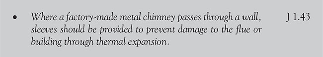
p.580
6.6.2.8.4 Carbon monoxide alarm siting

6.6.2.9 Protection from falling collision and impact
6.6.2.9.1 Guarding

6.6.2.9.2 Critical locations

6.6.2.10 Conservation of fuel and power
6.6.2.10.1 Limiting fabric parameters

![]() If a new conservatory or porch does not meet all these requirements, then it is not exempt and must comply with the relevant energy efficiency requirements of the 2014 revision of Approved Document L (Conservation of fuel and power).
If a new conservatory or porch does not meet all these requirements, then it is not exempt and must comply with the relevant energy efficiency requirements of the 2014 revision of Approved Document L (Conservation of fuel and power).
p.581
Table 6.6.16 Limiting fabric parameters for conservatory and porch extensions – walls

![]() Removing and not replacing any of the thermal separation between the building and an existing exempt extension, or extending the building’s heating system into the extension, means that the extension ceases to be exempt!
Removing and not replacing any of the thermal separation between the building and an existing exempt extension, or extending the building’s heating system into the extension, means that the extension ceases to be exempt!
6.6.2.10.2 Upgrading retained thermal elements
Extensions to dwellings should use either newly constructed thermal elements (which meet the requirements for the conservation of fuel and power) or existing (or new) windows, roof windows and rooflights that meet the standards shown in Table 6.6.17.

Table 6.6.17 Upgrading retained thermal elements

p.582
6.6.2.10.3 Building fabric
In accordance with the 2014 revision of Approved Document L (Conservation of fuel and power) and Regulation 7, reasonable provision shall be made for the conservation of fuel and power in buildings by limiting heat gains and losses through thermal elements and other parts of the building fabric.

![]() Note: U-values should be calculated using the methods and conventions set out in BR 443 (Conventions for U-value calculations), and should be based on the whole element or unit.
Note: U-values should be calculated using the methods and conventions set out in BR 443 (Conventions for U-value calculations), and should be based on the whole element or unit.
![]() Note: Where a swimming pool is constructed as part of a new building, reasonable provision should be made to limit the heat loss from the pool basin by achieving a U-value no worse than 0.25W/m2K (see BS EN ISO 13370).
Note: Where a swimming pool is constructed as part of a new building, reasonable provision should be made to limit the heat loss from the pool basin by achieving a U-value no worse than 0.25W/m2K (see BS EN ISO 13370).
6.6.2.10.4 Thermal bridges

To meet this requirement, it is recommended that you use construction joint details that have been calculated following the guidance set out in BRE Report BR 497, Conventions for Calculating Linear Thermal Transmittance and Temperature Factors.
6.6.2.10.5 Party walls and other thermal bypasses

![]() Note: Where outside air flows into the party wall cavity, a cold zone is created which causes heat loss through the wall sections on either side. The extent of air flow and heat changes depends on external conditions such as wind and temperature, and also on the effect of warmed air rising in the cavity and being replaced by cooler air drawn in from outside. The air movements involved can be significant and, if no steps are taken to restrict flows, the resulting heat loss can be large.
Note: Where outside air flows into the party wall cavity, a cold zone is created which causes heat loss through the wall sections on either side. The extent of air flow and heat changes depends on external conditions such as wind and temperature, and also on the effect of warmed air rising in the cavity and being replaced by cooler air drawn in from outside. The air movements involved can be significant and, if no steps are taken to restrict flows, the resulting heat loss can be large.
p.583

Fully filling the cavity may affect sound transmission through party walls. Developers who plan to fill a party wall cavity must satisfy the BCB that the requirements of Approved Document E (Resistance to sound) will be satisfied, either by adopting a full-fill detail accredited under the Robust Details scheme or through specific site testing.
When calculating the dwelling CO2 emission rate (DER) and Dwelling Fabric Energy Efficiency (DFEE) rate for a dwelling, a party wall U-value for the type of construction adopted, as set out in Table 6.6.18, should be applied.
The party wall is a particular case of the more general thermal bypass problem that occurs if the air barrier and the insulation layer are not contiguous and the cavity between them is subject to air movement. To avoid the consequent reduction in thermal performance, either the insulation layer should be contiguous with the air barrier at all points in the building envelope, or the space between the air barrier and insulation layer should be filled with solid material, such as in a masonry wall.
Table 6.6.18 U-values for party walls

p.584

6.6.2.11 Access to and use of dwellings

![]() Note: The loading for strengthened walls is considered suitable for many types of adaptations but additional localised strengthening may be required if adaptations are fitted that impose high point loads.
Note: The loading for strengthened walls is considered suitable for many types of adaptations but additional localised strengthening may be required if adaptations are fitted that impose high point loads.
![]() Remember M4(2) and M4(3) (Access to and use of buildings) are voluntary requirements and only apply in certain circumstances.
Remember M4(2) and M4(3) (Access to and use of buildings) are voluntary requirements and only apply in certain circumstances.
6.6.2.12 Electrical safety

p.585

Figure 6.6.62 Notifiable work in rooms containing a bath or a shower
6.6.2.13 Security – dwellings

![]() Note: Approved Document Q (Security in dwellings) came into effect on 1 October 2015 for use in England. It does not apply to work started before 1 October 2015, or work subject to a building notice, full plans application or initial notice submitted before that date provided the work was started on site before 1 October 2016.
Note: Approved Document Q (Security in dwellings) came into effect on 1 October 2015 for use in England. It does not apply to work started before 1 October 2015, or work subject to a building notice, full plans application or initial notice submitted before that date provided the work was started on site before 1 October 2016.
p.586
6.6.2.14 Physical infrastructure for high-speed electronic communications networks


Figure 6.6.63 Schematic example of in-building physical infrastructure for a single-occupancy building

p.587
![]() Note: Approved Document R (High-speed electronic communications networks) took effect on 1 January 2017 for use in England. It does not apply to work subject to a building notice, full plans application or initial notice submitted before 1 January 2017.
Note: Approved Document R (High-speed electronic communications networks) took effect on 1 January 2017 for use in England. It does not apply to work subject to a building notice, full plans application or initial notice submitted before 1 January 2017.

Figure 6.6.64 Schematic example of in-building physical infrastructure for a multi-dwelling building
6.7.1 Requirements

p.588

p.589

6.7.2 Meeting the requirements
6.7.2.1 Structure
6.7.2.1.1 Ceiling joists
Softwood timber used for roof construction including ceiling joists should be adequately treated to prevent infestation by the house longhorn beetle (Hylotrupes bajulus L.).
p.590

Figure 6.7.1 House longhorn beetle areas of infestation – Surrey

Figure 6.7.2 House longhorn beetle areas of infestation – Hampshire
p.591
![]() Note:
Note:
1. Guidance on suitable preservative treatments is given in The Wood Protection Association’s manual Industrial Wood Preservation: Specification and Practice (2012).
2. Guidance on the sizing of certain members in ceilings is given in the TRADA Span Tables for Solid Timber Members in Floors, Ceilings and Roofs (Excluding Trussed Rafter Roofs) for Dwellings.
3. Also see BS EN 1995–1-1, BSI Published Document PD 6693–1 and BS 8103–3.
6.7.2.1.2 Imposed loads on ceilings

6.7.2.2 Fire protection
6.7.2.2.1 Smoke alarms
There should be a smoke alarm in the circulation space within 7.5m of the door to every habitable room.

![]() Note: This guidance applies to ceilings that are predominantly flat and horizontal.
Note: This guidance applies to ceilings that are predominantly flat and horizontal.
6.7.2.2.2 Air-circulation systems in houses with a floor more than 4.5m above ground level
To avoid the possibility of smoke or fire spreading into a protected stairway.

p.592
6.7.2.2.3 Cavity barriers
A cavity barrier is termed as ‘any construction which is provided to restrict the movement of smoke or flame within a concealed space’.


Figure 6.7.3 Alternative cavity barrier in a roof space over a protected stairway in houses more than 4.5m above ground level

p.593
6.7.2.2.4 Suspended ceilings
A suspended, fire-resisting ceiling should meet the requirements given in Table 6.7.1.
Table 6.7.1 Limitations on fire-resisting suspended ceilings

![]() Note: For further details, see Approved Document B, Appendix A, Table A3.
Note: For further details, see Approved Document B, Appendix A, Table A3.
6.7.2.2.5 Ceiling linings
The materials used in ceilings can significantly affect the rate of growth and spread of a fire. It is therefore important to consider the material that is used in a circulation space even if it is unlikely to be the material that is first ignited. Therefore, to inhibit the spread of fire within the building, ceiling internal linings shall:
• adequately resist the spread of flame over their surfaces; and
• have, if ignited, a rate of heat release or a rate of fire growth that is reasonable in the circumstances.
![]() Note: Flame spread over ceiling surfaces is controlled by providing for the lining materials or products to meet given performance levels in tests appropriate to the materials or products involved.
Note: Flame spread over ceiling surfaces is controlled by providing for the lining materials or products to meet given performance levels in tests appropriate to the materials or products involved.
For the purpose of this requirement, the content of ceilings is as described in Table 6.7.2.
Table 6.7.2 Content of ceiling linings

p.594
6.7.2.2.6 Classification of linings
In general terms, the surface linings for ceilings should meet the classifications given in Table 6.7.3.
Table 6.7.3 Classification of linings

![]() Further guidance on ceiling linings are given in paragraphs 3.2 to 3.14 of Approved Document B V1.
Further guidance on ceiling linings are given in paragraphs 3.2 to 3.14 of Approved Document B V1.
6.7.2.2.7 Heat alarms
Heat detectors and heat alarms should conform to the following requirements.

6.7.2.2.8 Thermoplastic materials

p.595

6.7.2.2.9 Rooflights
Rooflights should meet the relevant classification in Table 6.7.4. They may be constructed of a thermoplastic material if:

Table 6.7.4 Limitations applied to thermoplastic rooflights and lighting diffusers in suspended ceilings and class 3 plastic rooflights

6.7.2.2.10 Lighting diffusers
The following guidance applies to lighting diffusers which form part of a ceiling and is not concerned with diffusers of light fittings which are attached to the soffit of, or suspended beneath, a ceiling (see Figure 6.7.4).
p.596
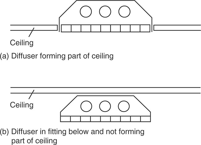
Figure 6.7.4 Lighting diffuser in relation to ceiling

p.597


Figure 6.7.5 Restrictions on Tp(b) lighting diffusers in relation to ceiling
6.7.2.2.11 Suspended or stretched-skin ceilings

p.598
The ceiling of a room may be constructed from panels of a thermoplastic material of the TP(d) flexible classification, provided that it is not part of a fire-resisting ceiling.

6.7.2.2.12 Fire-resisting ceilings

Table 6.7.5 Specific provisions of test for fire resistance of elements of structure – ceilings

p.599
Table 6.7.6 Limitations on fire-protecting ceilings

p.600
6.7.2.3 Resistance to the passage of sound
6.7.2.3.1 Ceiling and roof junctions
Where a type 1 separating wall is used it should be continuous to the underside of the roof.

6.8.2.3.2 Wall type 1 – solid masonry

Figure 6.7.6 Wall type 1 – solid masonry

p.601
6.7.2.3.3 Wall type 2 – cavity masonry

Figure 6.7.7 Wall type 2 – cavity masonry
![]() Note: Where a type 2 separating wall is used, it should be continuous to the underside of the roof.
Note: Where a type 2 separating wall is used, it should be continuous to the underside of the roof.

![]() Remember to fix the supporting frame of panels to the ceiling and floor only.
Remember to fix the supporting frame of panels to the ceiling and floor only.
p.602
6.7.2.3.4 Wall type 3 – masonry between independent panels

Figure 6.7.8 Wall type 3 – masonry between independent panels

p.603
![]() Where it is necessary to connect two leaves together, do not use ties of greater cross section than 40mm x 3mm fixed to the studwork at or just below ceiling height.
Where it is necessary to connect two leaves together, do not use ties of greater cross section than 40mm x 3mm fixed to the studwork at or just below ceiling height.
6.7.2.3.5 Wall type 4 – framed walls with absorbent material

![]() Note: There needs only be one frame in the roof space, provided there is a lining of two layers of plasterboard, each sheet of minimum mass per unit area 10kg/m2, on both sides of the frame.
Note: There needs only be one frame in the roof space, provided there is a lining of two layers of plasterboard, each sheet of minimum mass per unit area 10kg/m2, on both sides of the frame.
6.7.2.3.6 Junctions with walls
In all cases for the junction between the ceiling and the walls, the ceiling should be taken through the masonry and sealed with tape or caulked with sealant.
6.7.2.3.7 Ceiling and roof junctions
Where a type 1 separating wall is used it should be continuous to the underside of the roof.

6.7.2.3.8 Ceiling treatment
Each floor type requires one of the ceiling treatments described in this section. The description of each floor type contains a suffix A, B or C and that refers to the ceiling treatment used.
p.604

Figure 6.7.9 Floor type 1

Figure 6.7.10 Floor type 2

Figure 6.7.11 Floor type 3
p.605
![]() Note: Use of a better performing ceiling than that described in the guidance should improve the sound insulation of the floor provided there is no significant flanking transmission.
Note: Use of a better performing ceiling than that described in the guidance should improve the sound insulation of the floor provided there is no significant flanking transmission.
6.7.2.3.8.1 ceiling treatment A
This is an independent ceiling with absorbent material.

Figure 6.7.12 Ceiling treatment A (independent joists)

![]() Remember to seal the perimeter of the independent ceiling with tape or sealant and do not create a rigid or direct connection between the independent ceiling and the floor base.
Remember to seal the perimeter of the independent ceiling with tape or sealant and do not create a rigid or direct connection between the independent ceiling and the floor base.
p.606
6.7.2.3.8.2 ceiling treatment B
This is plasterboard on proprietary resilient bars with absorbent material.

Figure 6.7.13 Ceiling treatment B (resilient bars)

6.7.2.3.8.3 ceiling treatment C
This is plasterboard on timber battens or proprietary resilient channels with absorbent material.

Figure 6.7.14 Ceiling treatment C (timber battens or resilient channels)
p.607

![]() Electrical cables give off heat when in use and special precautions may be required when they are covered by thermally insulating materials.
Electrical cables give off heat when in use and special precautions may be required when they are covered by thermally insulating materials.
6.7.2.3.9 Interaction with floors
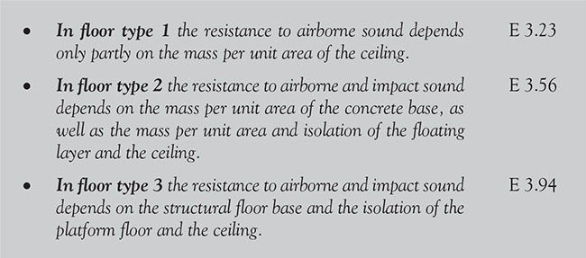
6.7.2.3.10 Work on existing buildings

p.608

p.609

Figure 6.7.15 Floor treatment 1

Figure 6.7.16 Floor treatment 1 – high window detail
![]() Do not create a rigid or direct connection between the independent ceiling and the floor base
Do not create a rigid or direct connection between the independent ceiling and the floor base
p.610
6.7.2.3.11 Stairs

6.7.2.4 Ventilation
F1 does not apply to a building or space within a building:
• into which people do not normally go
• which is used solely for storage
• which is a garage used solely in connection with a single dwelling.

6.7.2.4.1 Interaction of mechanical extract ventilation and open-flued combustion appliances

p.611


Figure 6.7.17 Locating permanent air vent openings (examples)

Figure 6.7.18 Air vent openings in a solid floor
p.612

Figure 6.7.19 The separation of combustible material from a factory-made metal chimney meeting BS 4543: Part 1

Figure 6.7.20 Example locations of access panels for concealed horizontal flues
p.613
6.7.2.5 Conservation of fuel and power

6.7.2.6 Access to and use of dwellings – Category 3 – Wheelchair user dwellings M4(3)

![]() Note: Requirements M3.35 and 3.36 are optional requirements for wheelchair user dwellings.
Note: Requirements M3.35 and 3.36 are optional requirements for wheelchair user dwellings.
p.614
Table 6.7.7 Cost effective U-Value targets when undertaking renovation work

p.615
6.7.2.7 Electrical safety


Figure 6.7.21 Notifiable work in rooms containing a bath or a shower
p.616
![]() This section also includes information on the composition and placement of rooflights.
This section also includes information on the composition and placement of rooflights.
The roof of a brick-built house is normally an aitched (sloping) roof comprising rafters fixed to a ridge board, braced by purlins, struts and ties and secured to wall-plates bedded on top of the walls. They are then usually clad with slates or tiles to keep the rain out.

Figure 6.8.1 Roof structure of brick-built house
Timber-framed houses usually have trussed roofs – prefabricated triangulated frames that combine the rafters and ceiling joists – which are lifted into place and supported by the rails. The trusses are joined together with horizontal and diagonal ties. A ridge board is not fitted, nor are purlins required. Roofing-felt battens and tiling are applied in the usual way.
![]() Note: Guidance on the sizing of timber floors and roofs for traditional house construction (known as the Timber Tables) are published by TRADA.
Note: Guidance on the sizing of timber floors and roofs for traditional house construction (known as the Timber Tables) are published by TRADA.
p.617
6.8.1 Requirements

p.618

p.619

p.620

6.8.2 Meeting the requirement
6.8.2.1 Structure
![]() Note: Unless they serve the function of a floor (i.e. a roof terrace), roofs are not treated as elements of structure.
Note: Unless they serve the function of a floor (i.e. a roof terrace), roofs are not treated as elements of structure.
6.8.2.1.1 General
Roofs shall be constructed so that they do both of the following:
![]() Note: A traditional cut timber roof (such as one using rafters, purlins and ceiling joists) generally has sufficient built-in resistance to instability and wind forces (e.g. from hipped ends, tiling battens, rigid sarking, etc.). However, the need for diagonal rafter bracing equivalent to that recommended in BS EN 1995–1-1 with its UK National Annex should be considered, especially for single-hipped and non-hipped roofs of greater than 40° pitch to detached houses.
Note: A traditional cut timber roof (such as one using rafters, purlins and ceiling joists) generally has sufficient built-in resistance to instability and wind forces (e.g. from hipped ends, tiling battens, rigid sarking, etc.). However, the need for diagonal rafter bracing equivalent to that recommended in BS EN 1995–1-1 with its UK National Annex should be considered, especially for single-hipped and non-hipped roofs of greater than 40° pitch to detached houses.
6.8.2.1.2 Imposed loads
Imposed loads on roofs are not permanent and can be variable.

p.621
6.8.2.1.3 Lateral support
Lateral support should be provided to help prevent sideways movement.

Table 6.8.1 Lateral support for walls


Figure 6.8.2 The sizes of openings in walls
p.622
Table 6.8.2 The value of Factor “X” (see Figure 6.8.2)

Vertical strapping (at least 1m in length) is required in gable wall unless the roof complies with all of the following:

Gable walls should be strapped to roofs as shown in Figure 6.8.3 (a) and (b) by tension straps.
Walls shall be tied to the roof structure vertically and horizontally and have a horizontal lateral restraint at roof level.

6.8.2.1.4 Timber
Softwood timber used for roof construction or fixed in the roof space (including ceiling joists within the void spaces of the roof), should be adequately treated to prevent infestation by the house longhorn beetle (Hylotrupes bajulus L.).

p.623


Figure 6.8.3 Lateral support at roof level
p.624

Figure 6.8.4 House longhorn beetle

Figure 6.8.5 House longhorn larva
p.625
![]() Note:
Note:
1. Guidance on suitable preservative treatments is given in The Wood Protection Association’s manual Industrial Wood Preservation: Specification and Practice.
2. Guidance on the sizing of certain members in floors and roofs is given in Span Tables for Solid Timber Members in Floors, Ceilings and Roofs (Excluding Trussed Rafter Roofs) for Dwellings, published by TRADA.
3. Also see BS EN 1995–1-1 (Design of Timber Structure), BSI Published Document PD 6693–1 and BS 8103–3.
6.8.2.1.5 Building height

6.8.2.1.6 Openings
Where an opening in a roof for a stairway adjoins a supported wall and interrupts the continuity of lateral support:
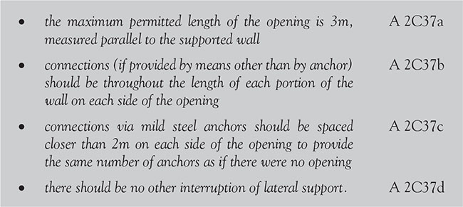
6.8.2.1.7 Proportions for masonry chimneys above the roof surface

p.626
6.8.2.1.8 Further guidance

p.627

6.8.2.1.9 Roof covering
Re-covering of roofs is commonly undertaken to extend the useful life of buildings; however, it should be remembered that roof structures may be required to carry underdrawing or insulation at a later date.

![]() Note: Transparent or translucent covering materials for roofs are not accessible except for normal maintenance and repair and are, therefore, excluded from the requirement to carry the concentrated imposed load upon roofs if they are not fragile or are otherwise suitably protected against collapse.
Note: Transparent or translucent covering materials for roofs are not accessible except for normal maintenance and repair and are, therefore, excluded from the requirement to carry the concentrated imposed load upon roofs if they are not fragile or are otherwise suitably protected against collapse.

![]() Note: To extend the useful life of a building, it is common for roofs to be re-covered. However, before work commences a check should be made to ensure that the existing roof structure is able to sustain any significant roof loading, and appropriate strengthening work or replacement of roofing members should be undertaken.
Note: To extend the useful life of a building, it is common for roofs to be re-covered. However, before work commences a check should be made to ensure that the existing roof structure is able to sustain any significant roof loading, and appropriate strengthening work or replacement of roofing members should be undertaken.
p.628
![]() ‘A significant change in roof loading’ is when the loading upon the roof is increased by more than 15 percent. This is classified as a material alteration.
‘A significant change in roof loading’ is when the loading upon the roof is increased by more than 15 percent. This is classified as a material alteration.
6.8.2.1.10 Pitched roofs covered with slates or tiles
Table 6.8.3 Pitched roofs – slates or tiles
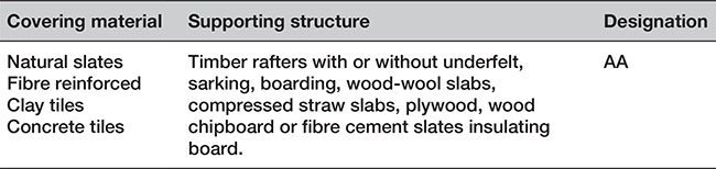
![]() Although Table 6.8.1 does not include guidance for pitched roofs covered with bitumen felt, it should be noted that there is a wide range of materials on the market, and information on specific products is readily available from manufacturers.
Although Table 6.8.1 does not include guidance for pitched roofs covered with bitumen felt, it should be noted that there is a wide range of materials on the market, and information on specific products is readily available from manufacturers.
6.8.2.1.11 Flat roofs covered with bitumen felt
A flat roof consisting of bitumen felt is (irrespective of the felt specification) deemed to be of designation AA if the felt is laid on a deck constructed of 6mm plywood, 12.5mm wood chipboard, 16mm (finished) plain-edged timber boarding, compressed straw slab, screeded wood-wool slab, profiled fibre-reinforced cement or steel deck (single or double skin) with or without fibre insulating board overlay, profiled aluminium deck (single or double skin) with or without fibre insulating board overlay, or concrete or clay-pot slab (in situ or precast), and has a surface finish of:
• bitumen-bedded stone chippings covering the whole surface to a depth of at least 12.5mm
• bitumen-bedded tiles of a non-combustible material
• sand and cement screed
• tarmacadam.
Table 6.8.4 Pitched roofs – self-supporting sheet

p.629
Table 6.8.4 Pitched roofs – self-supporting sheet (Continued)
6.8.2.1.12 Pitched or flat roofs covered with fully supported material
Table 6.8.5 Pitched roofs – fully supported material

![]() Note: Lead sheet supported by timber joists and plain-edged boarding should be regarded as having a ‘BA’ designation.
Note: Lead sheet supported by timber joists and plain-edged boarding should be regarded as having a ‘BA’ designation.
6.8.2.2 Fire safety
6.8.2.2.1 Emergency egress windows and external doors

p.630

Roof coverings are classed in accordance with the way they may be penetrated by fire and how flames spread. The codes are A–D in each category
Table 6.8.6 Roof Coverings classifications


![]() Note: Separation distances (i.e. the minimum distance from the roof, or part of the roof, to the relevant or notional boundary) shall be in accordance with Approved Document B, Volume 1, Table 5 according to the type of roof covering and the size and use of the building.
Note: Separation distances (i.e. the minimum distance from the roof, or part of the roof, to the relevant or notional boundary) shall be in accordance with Approved Document B, Volume 1, Table 5 according to the type of roof covering and the size and use of the building.
p.631
Table 6.8.7 Limitations on roof coverings

![]() Thatched roofs can sometimes be vulnerable to spontaneous combustion caused by heat transferred from flues building up in thick layers of thatch in contact with the chimney.
Thatched roofs can sometimes be vulnerable to spontaneous combustion caused by heat transferred from flues building up in thick layers of thatch in contact with the chimney.
6.8.2.2.2 Rooflights

Table 6.8.8 Classification of linings

![]() Note: Thermoplastic materials may be used in windows, rooflights and lighting diffusers in suspended ceilings.
Note: Thermoplastic materials may be used in windows, rooflights and lighting diffusers in suspended ceilings.

p.632
Table 6.8.9 Limitations applied to thermoplastic rooflights and lighting diffusers in suspended ceilings

6.8.2.2.3 Need for cavity barriers
A cavity barrier is any construction which is provided to restrict the movement of smoke or flame within a concealed space.

6.8.2.2.4 Compartmentation
To prevent the spread of fire within a building, whenever possible the building should be subdivided into compartments separated from one another by walls and/or floors of fire-resisting construction.

p.633


Figure 6.8.6 Junction of compartment wall with roof
6.8.2.2.5 Concealed spaces (cavities)
Concealed spaces or cavities in the construction of roofs will provide an easy route for smoke and flame to spread, which, because it is concealed, will present a greater danger than would a more obvious weakness in the fabric of the building. For this reason:
p.634

![]() Cavity barriers need not be provided between double-skinned corrugated or profiled insulated roof sheeting if the sheeting is a material of limited combustibility.
Cavity barriers need not be provided between double-skinned corrugated or profiled insulated roof sheeting if the sheeting is a material of limited combustibility.

Figure 6.8.7 Roof cavity barrier
6.8.2.3 Site preparation and resistance to moisture
Roofs are exposed to moisture in three ways:
• precipitation from the outside
• interstitial condensation
• condensation or mould growth on the internal surface.
![]() Note: There are particular issues when working in historic buildings to ensure that moisture ingress to the roof structure is limited and the roof can breathe. Where it is not possible to provide dedicated ventilation to pitched roofs, it is important to seal existing service penetrations in the ceiling and to provide draught proofing to any loft hatches. Any new loft insulation should be kept sufficiently clear of the eaves so that any adventitious ventilation is not reduced.
Note: There are particular issues when working in historic buildings to ensure that moisture ingress to the roof structure is limited and the roof can breathe. Where it is not possible to provide dedicated ventilation to pitched roofs, it is important to seal existing service penetrations in the ceiling and to provide draught proofing to any loft hatches. Any new loft insulation should be kept sufficiently clear of the eaves so that any adventitious ventilation is not reduced.
p.635
6.8.2.3.1 Precipitation
Roofs have the following functions.

6.8.2.3.2 Resistance to moisture from the outside
Roofs should be designed to protect the building from precipitation either by holding the precipitation at the face of the roof or by stopping it from penetrating beyond the back of the roofing system.

p.636

6.8.2.3.3 Resistance to damage from interstitial condensation
Roofs shall be designed and constructed in accordance with Clause 8.4 of BS 5250 and BS EN ISO 13788.

6.8.2.3.4 Resistance surface condensation and mould growth
Roofs shall be designed and constructed so that the thermal transmittance (U-value) does not exceed 0.35W/m2K at any point.

6.8.2.4 Resistance to the passage of sound
In order for the construction to be fully effective in the resistance to the passage of sound, care should be taken to correctly detail the junctions between the separating wall and the roof.
p.637
6.8.2.4.1 Wall type 1 – solid masonry

Figure 6.8.8 Wall type 1 – solid masonry

![]() Note:
Note:
1. A rigid connection between the inner and external wall leaves should be avoided.
2. If a rigid material is used, then it should only be rigidly bonded to one leaf.
p.638
6.8.2.4.2 Wall type 2 – cavity masonry

Figure 6.8.9 Wall type 2 – cavity masonry
![]() Note: Where a type 2 separating wall is used, it should be continuous to the underside of the roof.
Note: Where a type 2 separating wall is used, it should be continuous to the underside of the roof.

![]() Note:
Note:
1. A rigid connection between the inner and external wall leaves should be avoided.
2. If a rigid material is used, then it should only be rigidly bonded to one leaf.
p.639
![]() If the roof or loft space is not a habitable room (and there is a ceiling with a minimum mass per unit area of 10kg/m2 with sealed joints), the mass per unit area of the separating wall above the ceiling may be reduced to 150kg/m2 – but it should still be a cavity wall.
If the roof or loft space is not a habitable room (and there is a ceiling with a minimum mass per unit area of 10kg/m2 with sealed joints), the mass per unit area of the separating wall above the ceiling may be reduced to 150kg/m2 – but it should still be a cavity wall.
6.8.2.4.3 Wall type 3 – masonry between independent panels

Figure 6.8.10 Wall type 3 – masonry between independent panels

p.640

For wall type 3.3 (cavity masonry core):

6.8.2.4.4 Wall type 4 – framed walls with absorbent material

p.641
![]() Note: There need only be one frame in the roof space provided there is a lining of two layers of plasterboard, each sheet of minimum mass per unit area 10kg/m2, on both sides of the frame.
Note: There need only be one frame in the roof space provided there is a lining of two layers of plasterboard, each sheet of minimum mass per unit area 10kg/m2, on both sides of the frame.
6.8.2.4.5 Ceiling and roof junctions
Where a type 1 separating wall is used, it should be continuous to the underside of the roof.

6.8.2.5 Ventilation
6.8.2.5.1 Roof with a pitch of 15° or more
Pitched roof spaces should have ventilation openings as shown in Figures 6.8.11 and 6.8.12. There should be ventilation openings at least 10mm wide at eaves level to promote cross-ventilation. A pitched roof that has a single slope and abuts a wall should have ventilation openings at eaves level at least 10mm wide and at high level (i.e. at the junction of the roof and the wall) at least 5mm wide. Pitched roofs where the insulation follows the pitch of the roof need ventilation at the ridge at least 5mm wide.

Figure 6.8.11 Ventilating roof void – ceiling following pitch
p.642

Figure 6.8.12 Ventilating roof voids
(a) Pitched roof
(b) Lean-to roof
6.8.2.5.2 Roof with a pitch of less than 15°

Figure 6.8.13 Ventilating roof void – flat roof
Roof spaces should have ventilation openings at least 25mm wide (Figure 6.8.13) in two opposite sides to promote cross-ventilation. The void should have a free air space of at least 50mm between the roof deck and the insulation. Where the edges of the roof abut a wall or other obstruction in such a way that free air paths cannot be formed to promote cross-ventilation or the movement of air outside any ventilation openings would be restricted, an alternative form of roof construction should be adopted.
p.643
![]() Roofs with a span exceeding 10m may require more ventilation, totalling 0.6 percent of the roof area.
Roofs with a span exceeding 10m may require more ventilation, totalling 0.6 percent of the roof area.
Ventilation openings may be continuous or distributed along the full length and may be fitted with a screen, fascia, baffle, etc. Where necessary (i.e. for the purposes of health and safety), ventilation to small roofs such as those over porches and bay windows should always be provided and a roof that has a pitch of 70° or more shall be insulated as though it were a wall.
![]() If the ceiling of a room follows the pitch of the roof, ventilation should be provided as if it were a flat roof.
If the ceiling of a room follows the pitch of the roof, ventilation should be provided as if it were a flat roof.
6.8.2.5.3 Passive Stack Ventilation
In roof spaces, Passive Stack Ventilation (PSV) should follow the guidance below.

p.644

![]() Note: Placing the outlet terminal at the ridge of the roof is the preferred option, as it is not prone to wind gusts and/or certain wind directions.
Note: Placing the outlet terminal at the ridge of the roof is the preferred option, as it is not prone to wind gusts and/or certain wind directions.
6.8.2.6 Sanitation, hot water safety and water efficiency
6.8.2.6.1 Termination of discharge pipe

![]() As the discharge would consist of high temperature water and steam, asphalt, roofing felt and non-metallic rainwater goods may be damaged by such discharges.
As the discharge would consist of high temperature water and steam, asphalt, roofing felt and non-metallic rainwater goods may be damaged by such discharges.
p.645
6.8.2.7 Drainage and waste disposal
6.8.2.7.1 Rainfall protection

p.646
6.8.2.8 Combustion appliances
6.8.2.8.1 Factory-made chimneys


Figure 6.8.14 Positions for flue outlets (solid fuel applieances – easily ignited roof coverings)
p.647

Figure 6.8.15 Positions for flue outlets solid fuel appliances
6.8.2.8.2 Tests and examinations

6.8.2.9 Protection from falling, collision and impact
6.8.2.9.1 Siting of pedestrian guarding

p.648
6.8.2.9.2 Siting of vehicle barriers

6.8.2.10 Conservation of fuel and power
The main changes made by the 2016 amendments include the withdrawal of Regulations 29 to 33 of the Building Regulations 2010 and their replacement with Regulation 7A of the Energy Performance of Buildings (England and Wales) Regulations 2012, as well as changes in the wording of Regulations 24, 25, 26, 26A, 27 and 27A of the Building Regulations 2010.
![]() Note: Appendix B to this book (available at www.routledge.com/9781138285163) provides further information concerning the requirements for the conservation of fuel and power.
Note: Appendix B to this book (available at www.routledge.com/9781138285163) provides further information concerning the requirements for the conservation of fuel and power.
6.8.2.10.1 Limiting fabric standards

![]() Note: The Building Control Body (BCB) will pay particular attention if the roof U-value is claimed to be greater than 0.13W/m2K.
Note: The Building Control Body (BCB) will pay particular attention if the roof U-value is claimed to be greater than 0.13W/m2K.
6.8.2.10.2 Party walls

p.649
6.8.2.10.3 Historic and traditional buildings
![]() When undertaking work on any type of historic or traditional type of building, the aim should always be to improve energy efficiency as far as is reasonably practicable, without prejudicing the character of the host building or increasing the risk of long-term deterioration of the building fabric or fittings.
When undertaking work on any type of historic or traditional type of building, the aim should always be to improve energy efficiency as far as is reasonably practicable, without prejudicing the character of the host building or increasing the risk of long-term deterioration of the building fabric or fittings.

![]() Building Inspectors normally require the use of sympathetic treatment when restoring the historic character of a building that has been subject to previous inappropriate alteration (e.g. when replacing a roof or a rooflight).
Building Inspectors normally require the use of sympathetic treatment when restoring the historic character of a building that has been subject to previous inappropriate alteration (e.g. when replacing a roof or a rooflight).
6.8.2.10.4 Non-notifiable work
If you voluntarily install thermal insulation in a roof space or loft space and this is the only work carried out and the work is not carried out to comply with any requirement in the Building Regulations, then it classes as non-notifiable work.
6.8.2.10.5 Extensions
Extensions to dwellings should either use newly constructed thermal elements or make use of existing (or new) roof windows and rooflights, provided that they meet the requirements for the conservation of fuel and power.

![]() Note: Reductions in thermal performance can occur where the air barrier and the insulation layer are not contiguous and the cavity between them is subject to air movement. To avoid this problem, either:
Note: Reductions in thermal performance can occur where the air barrier and the insulation layer are not contiguous and the cavity between them is subject to air movement. To avoid this problem, either:
p.650
Table 6.8.10 Upgrading retained thermal elements

• the insulation layer should be contiguous with the air barrier at all points in the building envelope; or
• the space between the insulation layer and air barrier should be filled with solid material such as in a masonry wall.
6.8.2.10.6 Thermal bridges

A suitable approach to showing the requirement has been achieved would be to adopt Accredited Construction, details of which are on www.gov.uk.
6.8.2.11 Electrical safety
Part P applies to electrical installations that are outside the dwelling – for example photovoltaic panels on roofs – as well as to electrical installations within a roof space.
6.8.2.12 Security
Any easily accessible windows (including easily accessible rooflights) fitted in new dwellings should be secure windows (i.e. they should be made to a design that has been shown by test to meet the security requirements of British Standards publication PAS 24). An easily accessible window is one which is within 2m vertically of a flat or sloping roof (with a pitch of less than 30°) that is within 3.5m of ground level.
p.651
6.9.1 Requirements

p.652

![]() Note: For the purpose of the performance of wall linings, a wall includes fireplace surrounds, mantle shelves and also chimneys if they are attached to the building.
Note: For the purpose of the performance of wall linings, a wall includes fireplace surrounds, mantle shelves and also chimneys if they are attached to the building.
p.653
6.9.2 Meeting the requirements
In accordance with the Clean Air Act 1993, it is an offence for dark smoke to be emitted from a chimney of any building. This prohibition, however, does not apply to emissions that are solely due to the use of unsuitable fuel and:
• suitable fuel was unobtainable
• the least unsuitable fuel which was available was used; and
• all practicable steps had been taken to prevent or minimize the emission of dark smoke as the result of the use of that fuel.
![]() A person found guilty of an offence under this section is liable, on summary conviction, to a fine in accordance with the ‘standard scale’ contained in the Criminal Justice Act (at the time of publication ,the maximum fine for such offences was £5000).
A person found guilty of an offence under this section is liable, on summary conviction, to a fine in accordance with the ‘standard scale’ contained in the Criminal Justice Act (at the time of publication ,the maximum fine for such offences was £5000).
p.654
6.9.2.1 Structure
6.9.2.1.1 End restraint
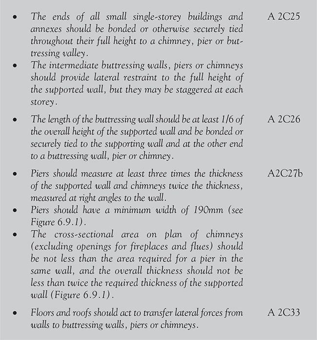
6.9.2.1.2 Masonry chimneys


Figure 6.9.1 Thickness of walls

Figure 6.9.2 Proportions for masonry chimneys

p.655

Figure 6.9.3 Piers and chimneys
p.656
6.9.2.2 Fire safety
Proprietary fire-stopping and sealing systems are available and may be used, as they have been shown by test to maintain the fire resistance of an element.

6.9.2.3 Combustion appliances and fuel storage systems
6.9.2.3.1 Construction

p.657

Figure 6.9.4 Chimneys and flues
p.658
A flue liner is the wall of the chimney that is in contact with the products of combustion (see Figure 6.9.4), such as a concrete flue liner, the inner liner of a factory-made chimney system or a flexible liner fitted into an existing chimney.
Down-draughts that could interfere with the combustion performance of an open-flued appliance shall be minimized. This can be achieved by using a factory-made draught stabilizer (see Figure 6.9.5) to prevent excessive variations in the draught.
A fireplace recess is a structural opening (sometimes called a builder’s opening) formed in a wall or in a chimney breast, from which a chimney leads and which has a hearth at its base.
p.659
Simple structural openings (Figure 6.9.6(a)) are suitable for closed appliances such as stoves, cookers or boilers, but gathers (Figure 6.9.6(b)) are necessary for accommodating open fires. Fireplace recesses are often lined with firebacks to accommodate inset open fires (Figure 6.9.6(c)). Lining components and decorative treatments fitted around openings reduce the opening area. It is the finished fireplace opening area which determines the size of flue required for an open fire in such a recess.
Flueblock chimney systems consist of a set of factory-made components, made from precast concrete, clay or other masonry units, which are designed for assembly on site to provide a complete chimney that has the appropriate performance for the intended appliance. There are two types of common systems, one being solely for use with gas-burning appliances and the other, often called a chimney block system, being primarily designed for solid fuel-burning appliances.

Figure 6.9.5 Draught diverters and draught stabilizers
p.660

Figure 6.9.6 Fireplace recesses
A flue box is a factory-made unit, usually made of metal, which is similar to a prefabricated appliance chamber except that it is designed to accommodate a gas-burning appliance in conjunction with a factory-made chimney.
A flue outlet is the point at which the products of combustion are discharged from the flue to the outside atmosphere, such as the top of a chimney pot or flue terminal.
A fluepipe is a pipe, either single walled (bare or insulated) or double walled, which connects a combustion appliance to a flue in a chimney.
![]() Note: Chimneys and flues should also provide satisfactory control of water condensation.
Note: Chimneys and flues should also provide satisfactory control of water condensation.
![]() In the gas industry, the chimney for a gas appliance is commonly called the flue.
In the gas industry, the chimney for a gas appliance is commonly called the flue.
p.661
6.9.2.3.2 Open fire with a throat and gather
A throat is a contracted part of the flue between a fireplace recess and its chimney (see Figure 6.9.4). Throats are usually formed from prefabricated components.
Permanently open air vents should have a total free area of at least 50 percent of the throat opening area (see Figure 6.9.7).

Figure 6.9.7 Open fireplaces – throat and fireplace components
p.662
6.9.2.3.3 Open fire with no throat (e.g. a fire under a canopy)
Permanently open air vents should have a total free area of at least 50 percent of the cross-sectional area of the flue (see Figure 6.9.8).

Figure 6.9.8 Canopy for an open solid fuel fire
6.9.2.3.4 Appliances burning solid fuel (with a rated output up to 50kW)

6.9.2.3.5 Other appliances (such as a stove, cooker or boiler)
Stoves, cookers or boilers should have permanently open air vent(s).
6.9.2.3.6 Carbon monoxide alarms
![]() Note: Carbon monoxide (CO) is a colourless, odourless and tasteless gas that is slightly less dense than air. It is toxic to humans and animals when encountered in higher concentrations, although it is also produced in normal animal metabolism in low quantities, and is thought to have some normal biological functions. In the atmosphere it is spatially variable and short-lived, having a role in the formation of ground level ozone. Carbon dioxide is normally expelled through the lungs, but if there is too much carbon dioxide in the blood stream then it can cause hypercapnia, which will trigger a reflex which increases breathing and access to oxygen, such as arousal and turning the head during sleep. A failure of this reflex can be fatal, as in sudden infant death syndrome.
Note: Carbon monoxide (CO) is a colourless, odourless and tasteless gas that is slightly less dense than air. It is toxic to humans and animals when encountered in higher concentrations, although it is also produced in normal animal metabolism in low quantities, and is thought to have some normal biological functions. In the atmosphere it is spatially variable and short-lived, having a role in the formation of ground level ozone. Carbon dioxide is normally expelled through the lungs, but if there is too much carbon dioxide in the blood stream then it can cause hypercapnia, which will trigger a reflex which increases breathing and access to oxygen, such as arousal and turning the head during sleep. A failure of this reflex can be fatal, as in sudden infant death syndrome.
Under current Building Regulations, in England and Wales it is now a mandatory requirement to fit carbon monoxide alarms where new or replacement fixed solid fuel appliances are installed in a home.
In Northern Ireland, it a legal requirement to fit CO alarms in all homes where a new or replacement appliance, not used solely for cooking, is installed.


6.9.2.3.7 Masonry chimneys (change of use)
6.9.2.3.8 Reuse of existing flues
Where it is proposed to bring a flue in an existing chimney back into use or to reuse a flue with a different type or rating of appliance, the flue and the chimney should be checked and, if necessary, altered to ensure that they satisfy the requirements for the proposed use.
If a chimney has been relined in the past using a metal lining system and the appliance is being replaced, the metal liner should also be replaced unless the metal liner can be proven to be recently installed and can be seen to be in good condition.
p.663

Figure 6.9.9 Fire protection of chimneys passing through other dwellings
6.9.2.3.9 Flueblock chimneys
A flueblock chimney system is a factory-made set of components that are manufactured from precast concrete, clay or other masonry units and assembled on site to provide a complete chimney.
There are two types – one for gas-burning appliances and the other (often called a chimney block system) for solid fuel-burning appliances.


6.9.2.3.10 Masonry and flueblock chimneys

Figure 6.9.10 Wall thickness for masonry and flueblock chimneys (dimensions in mm)
![]() Figure 6.9.11 shows a method of meeting this requirement so that combustible material is at least:
Figure 6.9.11 shows a method of meeting this requirement so that combustible material is at least:
• 200mm from the inside surface of a flue or fireplace recess; and/or
• 40mm from the outer surface of a masonry chimney or fireplace recess.

Figure 6.9.11 Minimum separation distances for combustible material in or near a chimney
p.664

6.9.2.3.11 Factory-made metal chimneys
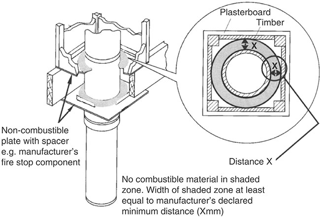
Figure 6.9.12 The separation of combustible material from a factory-made metal chimney meeting BS 4543: Part 1.
![]() Casing the chimney in non-combustible material is recommended.
Casing the chimney in non-combustible material is recommended.

6.9.2.3.12 Debris collection space
6.9.2.3.13 Flues
Approved Document J provides guidance on how to meet the requirements in terms of constructing a flue or chimney, where each flue serves one appliance only.

p.665
![]() Each solid fuel appliance should have its own flue.
Each solid fuel appliance should have its own flue.
6.9.2.3.14 Condensates in flues

6.9.2.3.15 Flue systems


Figure 6.9.13 Bends in flues

p.666
6.9.2.3.15.1 flues in chimneys
Table 6.9.1 Size of flues in chimneys

p.667
6.9.2.3.15.2 height of flues


Figure 6.9.14 Flue outlet positions for solid fuel appliances.
Table 6.9.2 Flue outlet positions

6.9.2.3.15.3 size of flues

p.668
6.9.2.3.15.4 flue outlets

![]() In areas where nests of squirrels or jackdaws are likely, the fitting of a protective cage designed for solid fuel use and having a mesh size between 6 and 25mm is advisable.
In areas where nests of squirrels or jackdaws are likely, the fitting of a protective cage designed for solid fuel use and having a mesh size between 6 and 25mm is advisable.

p.669
6.9.2.3.15.5 flues discharging at low level near boundaries

p.670
6.9.2.3.15.6 flue outlet clearances – thatched or shingled roof

p.671

Figure 6.9.15 Location of outlets from flues serving oil-fired appliances
Table 6.9.3 Minimum separation distances for outlets
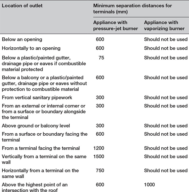
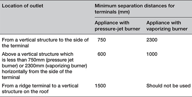
p.672

Figure 6.9.16 Flue outlet positions for solid fuel appliances – discharging near easily ignited roof coverings
p.673
6.9.2.3.15.7 thatched roofs
Thatched roofs can sometimes be vulnerable to spontaneous combustion caused by heat being transferred from flues and building up in thick layers of thatch that are in contact with the chimney. To reduce the risk, it is recommended that rigid twin-walled insulated metal flue liners are used within a ventilated (top and bottom) masonry chimney void, provided they are adequately supported and not in direct contact with the masonry.
Non-metallic chimneys and cast in-situ flue liners can also be used, provided the heat transfer to the thatch is assessed in relation to the depth of thatch and risk of spontaneous combustion.
p.674
Spark arrestors are not generally recommended, as they can be difficult to maintain and may increase the risk of flue blockage and flue fires.
p.675
![]() Note: Further information and recommendations are contained in HETAS Information Paper 1/007, Chimneys in Thatched Properties.
Note: Further information and recommendations are contained in HETAS Information Paper 1/007, Chimneys in Thatched Properties.
6.9.2.3.15.8 connecting flue pipes

![]() Combustible materials in the building fabric should be protected from the heat dissipation from flues so that they are not at risk of catching fire.
Combustible materials in the building fabric should be protected from the heat dissipation from flues so that they are not at risk of catching fire.
p.676
6.9.2.3.15.9 concealed flues

p.677
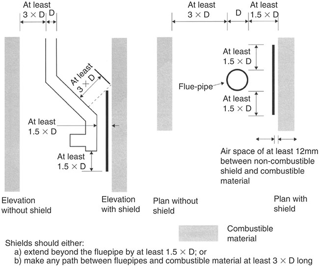
Figure 6.9.17 Protecting combustible material from uninsulated flue pipes for solid fuel appliances
p.678

p.679
6.9.2.3.15.10 ventilation

![]() Rooms or spaces intended to contain flueless appliances may need permanent ventilation and purge ventilation (e.g. openable windows) or adjustable ventilation and rapid ventilation.
Rooms or spaces intended to contain flueless appliances may need permanent ventilation and purge ventilation (e.g. openable windows) or adjustable ventilation and rapid ventilation.

6.9.2.3.15.11 reuse of existing flues

p.680
![]() Oversize flues can be unsafe. A flue may, however, be lined to reduce the flue area to suit the intended appliance.
Oversize flues can be unsafe. A flue may, however, be lined to reduce the flue area to suit the intended appliance.
6.9.2.3.15.12 repair of flues
![]() If the installation and maintenance of a fireplace and/or chimney are deemed as being a material change of use, it is a mandatory requirement that the building is brought up to the standards required by Approved Documents J1 to J3.
If the installation and maintenance of a fireplace and/or chimney are deemed as being a material change of use, it is a mandatory requirement that the building is brought up to the standards required by Approved Documents J1 to J3.
p.681
If renovation, refurbishment or repair amounts to or involves the provision of a new or replacement flue liner, it is considered ‘building work’ within the meaning of Regulation 3 of the Building Regulations and must, therefore, not be undertaken without prior notification to the Local Authority. Examples of work that would need to be notified include:

![]() Note: If you are in any doubt about this requirement, you should consult the Building Control Department of your Local Authority or an Approved Inspector.
Note: If you are in any doubt about this requirement, you should consult the Building Control Department of your Local Authority or an Approved Inspector.
6.9.2.3.15.13 relining flues
Flues should be swept to remove deposits before being relined.
p.682
![]() In certain circumstances, relining is considered ‘building work’ within the meaning of Regulation 3 of the Building Regulations and must, therefore, not be undertaken without prior notification to the Local Authority. If you are in doubt you should consult the Building Control department of your Local Authority or an Approved Inspector.
In certain circumstances, relining is considered ‘building work’ within the meaning of Regulation 3 of the Building Regulations and must, therefore, not be undertaken without prior notification to the Local Authority. If you are in doubt you should consult the Building Control department of your Local Authority or an Approved Inspector.
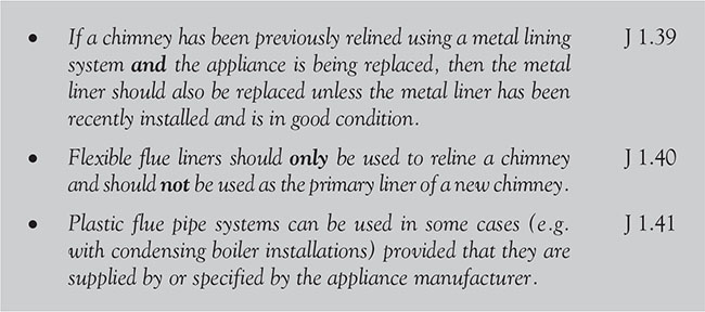
p.683
6.9.2.3.16 Fireplaces
Examples of Length (L) and Height (H) for large and unusual fireplace openings are shown in Figure 6.9.18.
6.9.2.3.1.6.1 general


Figure 6.9.18 Large or unusual fireplace openings
p.684
![]() Note: Lining components and decorative treatments fitted around openings reduce the opening area. It is the finished fireplace opening area that determines the size of flue required for an open fire in such a recess.
Note: Lining components and decorative treatments fitted around openings reduce the opening area. It is the finished fireplace opening area that determines the size of flue required for an open fire in such a recess.
Simple recesses are suitable for closed appliances such as room heaters, stoves, cookers or boilers (but are not suitable for an open fire without a canopy!) and can be used for accommodating open fires and free-standing fire baskets. Fireplace recesses are often lined with firebacks to accommodate inset open fires.
p.685
6.9.2.3.1.6.2 fireplace recesses


Figure 6.9.19 Fireplace recesses
(a) Solid wall (b) Cavity wall (c) Back-to-back (within the same dwelling)
p.686
Table 6.9.4 Flue outlet positions

p.687
6.9.2.3.1.6.3 fireplace lining components

Table 6.9.5 Prefabricated appliance chambers: minimum thickness

p.688
p.689
6.9.2.3 1.6.4 construction of fireplace gathers
To minimize resistance to the proper working of flues, tapered gathers should be provided in fireplaces for open fires or corbelling of masonry, as shown in Figure 6.9.20.
p.690

Figure 6.9.20 Construction of fireplace gathers – using masonry
Alternatively, a suitable canopy (as shown in Figure 6.9.21) or a prefabricated appliance chamber incorporating a gather may be used.
p.691

Figure 6.9.21 Canopy for an open fuel fire
This can be achieved by using prefabricated gather components built into a fireplace recess, as shown in 6.9.22.
p.692

Figure 6.9.22 Construction of fireplace gathers – using prefabricated components
p.693

6.9.2.3.17 Hearths
A hearth is a base intended to safely isolate a combustion appliance from people, combustible parts of the building fabric and soft furnishings. (see Figure 6.9.23).


Figure 6.9.23 The functions of a hearth
p.694
6.9.2.3.17.1 Construction of hearths

p.695

Figure 6.9.25 Constructional hearth suitable for solid fuel appliances (including open fires) – section
p.696
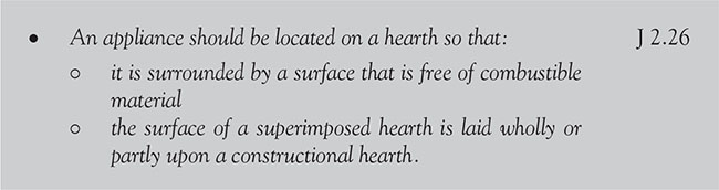
![]() Note: The edges of this surface should be marked (e.g. by a change in level) to provide a warning to the building occupants and to discourage combustible floor finishes such as a carpet from being laid too close to the appliance.
Note: The edges of this surface should be marked (e.g. by a change in level) to provide a warning to the building occupants and to discourage combustible floor finishes such as a carpet from being laid too close to the appliance.


Figure 6.9.26 Non-combustible hearth surface surrounding a solid fuel appliance
(a) Fireplace recess. (b) Free-standing.
Some ways of making these provisions are shown in Fig 6.9.27.

Figure 6.9.27 Ways of providing hearths
p.697
6.9.2.3.17.2 walls adjacent to hearths

![]() Note: There is no requirement for protection of the wall where X is more than 150mm
Note: There is no requirement for protection of the wall where X is more than 150mm
p.698
6.9.2.3.18 Dry lining around fireplace openings

p.699

Figure 6.9.28 Walls adjacent to hearths
Table 6.9.6 Walls adjacent to hearths thickness and height

6.9.2.3.19 Provision of information
On completion of work:

p.700
![]() Note: Guidance on testing is given at Appendix E to Approved Document J:2010.
Note: Guidance on testing is given at Appendix E to Approved Document J:2010.

![]() See Appendix A to Approved Document J:2010 for detailed checklists for checking and testing of hearths, fireplaces, flues and chimneys.
See Appendix A to Approved Document J:2010 for detailed checklists for checking and testing of hearths, fireplaces, flues and chimneys.

p.701
6.9.2.3.19.1 Notice plates for hearths and flues


![]() Notice plates should be securely fixed either next to the:
Notice plates should be securely fixed either next to the:
• electricity consumer unit; or
• chimney or hearth described; or
• water supply stopcock.
p.702
6.9.2.3.20 Maintenance
6.9.2.3.20.1 access to combustion appliances for maintenance

p.703
6.9.2.3.20.2 gas-burning devices
The Gas Safety (Installation and Use) Regulations require that:
• gas fittings, appliances and gas storage vessels must only be installed by a person with the required competence; and
• any person having control to any extent of gas work must ensure that the person carrying out that work has the required competence; and
• any person carrying out gas installation, whether an employee or self-employed, must be a member of a class of persons approved by the HSE and registered with the Gas Safety Register.
Important elements of the regulations include the following.
p.704

![]() Note: Outlets from flues should be situated externally so as to allow the products of combustion to dispel and, if a balanced flue, the intake of air (Figure 6.9.29).
Note: Outlets from flues should be situated externally so as to allow the products of combustion to dispel and, if a balanced flue, the intake of air (Figure 6.9.29).
p.705
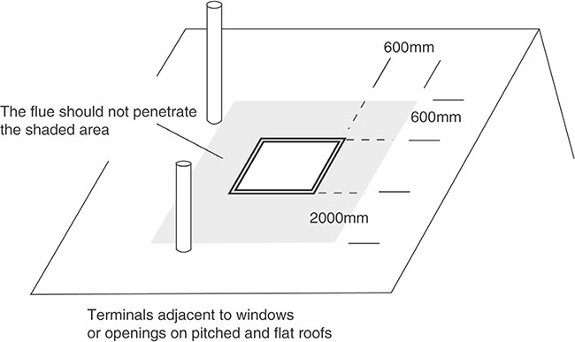
Figure 6.9.29 Location of outlets near roof windows from flues serving gas appliances.
p.706
6.9.2.3.21 Gas fires (other than flueless gas fires)
A flueless appliance is designed to be used without connection to a flue. Its products of combustion mix with the surrounding room air and are eventually transported to the outside as stale air leaves the room (see Figure 6.9.30).
![]() Gas-fired appliances should only be located where accidental contact is unlikely and where they can be surrounded by a non-combustible surface which provides adequate separation from combustible materials.
Gas-fired appliances should only be located where accidental contact is unlikely and where they can be surrounded by a non-combustible surface which provides adequate separation from combustible materials.
p.707

Figure 6.9.30 Flueless installation
p.708
6.9.2.3.22 Back boilers


Figure 6.9.31 Bases for back boilers
p.709
6.9.2.3.23 Kerosene and gas-oil burning appliances
Kerosene (class C2) and gas-oil (class D) appliances have the following, additional, requirements.

![]() Note: Figure 6.9.33 (and Table 6.9.7) indicates typical positioning to meet this requirement.
Note: Figure 6.9.33 (and Table 6.9.7) indicates typical positioning to meet this requirement.

Figure 6.9.32 Location of outlets from flues serving kerosene and oil-fired appliances
p.710
Table 6.9.7 Location of outlets from flues serving oil-fired appliances

![]() Note:
Note:
(1) Terminals should only be positioned on walls where appliances have been approved for such configurations when tested in accordance with BS EN 303 – 1 or OFTEC standard OFS A100 or OFS A101.
(2) An opening means an openable element, such as an openable window, or a permanent opening such as a permanently open air vent.
(3) Notwithstanding the dimensions above, a terminal should be at least 300mm from combustible material (e.g. a window frame).
p.711
(4) A way of providing protection of combustible material would be to fit a heat shield at least 750mm wide.
(5) Outlets for vertical balanced flues in locations M, N and O should be in accordance with the manufacturer’s instructions.
(6) Where a terminal is used with a vapourizing burner, the terminal should be at least 2300mm horizontally from the roof.

p.712
6.9.2.3.24 Relining chimney flues (for oil appliances)
In some circumstances, lining or relining flues could be considered building work, in which case the works must be brought up to the standards required by Approved Documents J2 to J4.
6.9.2.3.25 Hearths for oil appliances

6.9.2.4 Conservation of fuel and power
6.9.2.4.1 Secondary heating


p.713
6.10.1 Requirements
p.714

6.10.2 Meeting the requirements
6.10.2.1 Structure
6.10.2.1.1 Interruption of Lateral support
6.10.2.1.2 Wall cladding on escape routes
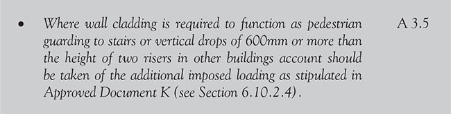
6.10.2.2 Fire safety
For a typical one or two-storey dwelling, the requirement is limited to the provision of smoke alarms and to the provision of openable windows for emergency exit (Approved Document B Volume 1 B1.i). As the upper surfaces of floors and stairs are not significantly involved in a fire until it is well developed, they do not play an important part in fire spread in the early stages of a fire.
p.715
6.10.2.2.1 Means of escape
The basic principles for the design of means of escape are that there should be alternative way for people to flee from most situations.

p.716
6.10.2.2.2 Unprotected and protected escape routes
The unprotected part of an escape route is that part which a person has to traverse before reaching either the safety of a final exit or the comparative safety of a protected escape route, i.e. a protected corridor or protected stairway.

Even with protected horizontal escape routes, the distance to a final exit or protected stairway needs to be limited because the structure does not give protection indefinitely. Protected stairways are designed to provide virtually ‘fire sterile’ areas which lead to places of safety outside the building. Once inside a protected stairway, a person can be considered to be safe from immediate danger from flame and smoke. They can then proceed to a place of safety at their own pace.
p.717

Figure 6.10.1 Means of escape from a dwelling

6.10.2.2.3 Positioning of smoke and heat alarms


p.718
6.10.2.2.4 Galleries

6.11.2.2.5 Cavity barriers

6.10.2.2.6 Air-circulation systems in houses with a floor more than 4.5m above ground level
Precautions are required to avoid the possibility of an air-circulation system allowing smoke or fire to spread into a protected stairway by ensuring that the following precautions are taken.


6.10.2.2.7 Passenger lifts

Figure 6.10.2 Alternative cavity barrier in a roof space over a protected stairway in houses more than 4.5m above ground level
6.10.2.2.8 Windows
A single window can be accepted to serve two rooms as long as both rooms have their own access to the stairs. A communicating door between the rooms should also be provided so that it is possible to gain access to the window without passing through the stair enclosure.

![]() Note: If direct escape to a place of safety is impracticable, it should be possible to reach a place of relative safety such as a protected stairway within a reasonable travel distance.
Note: If direct escape to a place of safety is impracticable, it should be possible to reach a place of relative safety such as a protected stairway within a reasonable travel distance.
6.10.2.2.9 Escape stairs
6.10.2.2.9.1 external escape stairs
When an external escape stair may be used:


Figure 6.10.3 Fire resistance of areas adjacent to external stairs
6.10.2.2.9.2 protection of escape stairs


![]() Note: The provisions described in 2.6 and 2.7 need not be followed if the dwelling has more than one internal stairway, which both afford effective alternative means of escape and are physically separated from each other.
Note: The provisions described in 2.6 and 2.7 need not be followed if the dwelling has more than one internal stairway, which both afford effective alternative means of escape and are physically separated from each other.

Figure 6.10.4 Alternative arrangements for final exits
![]() A single stairway is at risk of becoming blocked by smoke from a fire.
A single stairway is at risk of becoming blocked by smoke from a fire.
6.10.2.2.10 Basements

6.10.2.2.11 Loft conversions
6.10.2.3 Resistance to the passage of sound
The common internal parts of buildings which contain flats or rooms for residential purposes shall be designed in such a way that reverberation around these common parts of the building is minimized.
6.10.2.3.1 Stair treatments
A ‘stair treatment’ (shown in Figure 6.10.5) consists of a stair covering an independent ceiling with absorbent material.

Figure 6.10.5 Stair covering and independent ceiling with absorbent material
The soft covering should be at least 6mm thick, laid over the stair treads and securely fixed (e.g. glued) so it does not become a safety hazard.
If there is a cupboard under all, or part, of the stair:

If there is no cupboard under the stair, an independent ceiling should be constructed below the stair.

E 4.27
Where a staircase performs a separating function, it shall conform to Approved Document B (Fire safety; see Section 6.10.2.1). Stairs that separate a dwelling from another dwelling (or part of the same building) shall comply with the following.


Figure 6.10.7 illustrates the relevant parts of the building that should be protected from airborne and impact sound in order to satisfy Requirement E2’s.

Figure 6.10.6 Floor treatment 1 independent ceiling with absorbent material
Table 6.10.1 Dwellings – performance standards for separating floors and stairs that have a separating function


Figure 6.10.7 Airborne and impact sound requirements
![]() Note:
Note:
1. The sound insulation values in Table 6.10.1 include a built-in allowance for ‘measurement uncertainty’, and so, if any of these test values are not met, that particular test will be considered as failed.
2. Occasionally, a higher standard of sound insulation may be required between spaces used for normal domestic purposes and noise generated in and to an adjoining communal or non-domestic space. In these cases, it would be best to seek specialist advice before committing yourself.
3. If the stair is not enclosed, the potential sound insulation of the internal floor will not be achieved; nevertheless, the internal floor should still satisfy conditions stated above in Requirement E2.
4. In some cases, it may be that an existing stair in a building will achieve these performance standards without the need for remedial work (e.g. if the existing construction was already compliant).
6.10.2.3 2 Sound insulation testing
The person completing the building work should arrange for sound insulation testing to be carried out (by a test body with appropriate third-party accreditation) in accordance with the procedure described in Annex B of Approved Document E.

![]() Note: Some properties, for example loft apartments, may be sold before being fitted out with internal walls and other fixtures and fittings. In these cases, sound insulation measurements should be made between the available spaces.
Note: Some properties, for example loft apartments, may be sold before being fitted out with internal walls and other fixtures and fittings. In these cases, sound insulation measurements should be made between the available spaces.
If stairs form a separating function they are subject to the same sound insulation requirements as floors. In this case, the resistance to airborne sound depends mainly on:
• the mass of the stair
• the mass and isolation of any independent ceiling
• the airtightness of any cupboard or enclosure under the stairs
• the stair covering (which reduces impact sound at source).
6.10.2.3.3 Reverberation
Requirement E3 states that domestic buildings shall be designed and constructed so as to restrict the transmission of echoes. The guidance notes provided in Approved Document E cover two methods (Method A and Method B) which can be used to determine the amount of additional absorption to be used in corridors, hallways, stairwells and entrance halls that give access to flats and rooms for residential purposes. Method A is applicable to stairs and requires the following to be observed:


![]() Note: Method B can generally be satisfied by the use of proprietary acoustic ceilings.
Note: Method B can generally be satisfied by the use of proprietary acoustic ceilings.
6.10.2.3.4 Piped services
Piped services (excluding gas pipes) and ducts that pass through separating floors should be surrounded with sound-absorbent material for their full height and enclosed in a duct above and below the floor.
6.10.2.3.4.1 junctions with floor penetrations (excluding gas pipes)


Figure 6.10.8 Junctions with floor penetrations (excluding gas pipes)
6.10.2.3.4.2 junctions with floor penetrations (including gas pipes)

![]() Note: In the Gas Safety Regulations, there are requirements for ventilation of ducts at each floor where they contain gas pipes. Gas pipes may be contained in a separate ventilated duct or they can remain inducted and if a gas service is installed it shall comply with the Gas Safety (Installation and Use) Regulations 1998, SI 1998 No. 2451.
Note: In the Gas Safety Regulations, there are requirements for ventilation of ducts at each floor where they contain gas pipes. Gas pipes may be contained in a separate ventilated duct or they can remain inducted and if a gas service is installed it shall comply with the Gas Safety (Installation and Use) Regulations 1998, SI 1998 No. 2451.
6.10.2.4 Protection from falling, collision and impact
In a dwelling, the maximum pitch for a private stair is 42°. The normal relationship between the dimensions of the rise and going is twice the rise plus the going (2R + G) equals between 550mm and 700mm. Any external tapered steps and stairs that are part of the building should have a going on each step of a minimum of 280mm.
For existing buildings the dimensional requirements in Table 6.10.2 should be followed, unless due to dimensional constraints it is not possible. Any alternative proposal should be agreed with the BCB and included in an access strategy.
6.10.2.4.1 Alternating tread stairs
Table 6.10.2 Rise and going

Alternating tread stairs may only be used in a loft conversion.

6.10.2.4.2 Stairs and ladder
6.10.2.4.2.1 steepness of stairs – rise and going
The rise and going should be in accordance with Figure 6.10.10.


Figure 6.10.9 Alternating tread stair

Figure 6.10.10 Measuring rise and going
6.10.2.4.2.2 Construction of steps

For common access areas in buildings that contain flats:


Figure 6.10.11 Examples of suitable tread nosings
6.10.2.4.3 Headroom for stairs
For all buildings:

Figure 6.10.12 Minimum headroom
For loft conversions in dwellings:


Figure 6.10.13 Reduced headroom for loft conversions
6.10.2.4.4 Width of flights of stairs
If the flight is more than 2m wide, divide it into flights a minimum of 1000mm wide, as shown in Figure 6.10.14. In exceptional circumstances, where severely sloping plots are involved (and a stepped change of level within the entrance storey is unavoidable), the minimum stair width within the entrance storey of a dwelling is 900mm. K 1.16


Figure 6.10.14 Dividing flights
6.10.2.4.5 Length of flight of stairs for all buildings

6.10.2.4.6 Landings for stairs


Figure 6.10.16 Cupboards opening on to a landing
Note: Also see Approved Document B (Fire Safety) in Section 6.10.2.1.


Figure 6.10.17 Landings next to doors in dwellings
6.10.2.4.7 Tapered treads

6.10.2.4.8 Spiral and helical stairs

![]() Not to be confused with BS EN ISO 5395–2 which is for Garden equipment. Safety requirements for combustion-engine-powered lawnmowers. Pedestrian-controlled lawnmowers!
Not to be confused with BS EN ISO 5395–2 which is for Garden equipment. Safety requirements for combustion-engine-powered lawnmowers. Pedestrian-controlled lawnmowers!

Figure 6.10.18 Measured tapered treads
6.10.2.4.9 Handrails for stairs


Figure 6.10.19 Key dimensions for handrails for common stairs in blocks of flats

Figure 6.10.20 Handrail design

6.10.2.4.10 Guarding of stairs

6.10.2.4.11 Access for maintenance
Where the stairs or ladders will be used to access areas for maintenance, they should comply with the provisions of BS 5395–3 and the Construction (Design and Management) Regulations 2015 as appropriate.
6.10.2.4.12 Fixed ladders
In dwellings, a fixed ladder may be used – with fixed handrails on both sides – only for access in a loft conversion that contains one habitable room.
![]() Retractable ladders may not be used as means of escape.
Retractable ladders may not be used as means of escape.
6.10.2.4.13 Ramps
6.10.2.4.13.1 construction of ramps
![]() Note: If the change in level is less than 300mm, you must provide a ramp instead of a single step.
Note: If the change in level is less than 300mm, you must provide a ramp instead of a single step.

6.10.2.4.13.2 design of ramps
For all buildings ramps and landings should be designed in accordance with Figure 6.10.21.

Figure 6.10.21 Ramp design
![]() Note: For ramps that are likely to be used by children under five years old, the construction of the guarding shall be such that a 100mm sphere cannot pass through any openings in the guarding and children will not easily climb the guarding.
Note: For ramps that are likely to be used by children under five years old, the construction of the guarding shall be such that a 100mm sphere cannot pass through any openings in the guarding and children will not easily climb the guarding.
6.10.2.4.13.4 obstruction of ramps
All ramps should be kept clear of all permanent obstructions.
6.10.2.4.13.5 steepness of ramps

Figure 6.10.22 The relationship of ramp gradient and going of a ramp
6.10.2.4.14 Protection from falling
Guarding should be provided whenever it is considered necessary from the point of view of safety to guard:

6.10.2.4.14.1 design of guarding

![]() Note: Where glazing is used as part the guarding, refer also to Approved Document K5
Note: Where glazing is used as part the guarding, refer also to Approved Document K5

Figure 6.10.23 Guarding design
![]() Note: Typical locations for guarding are shown in Figure 6.10.24. Further guidance on the design of barriers and infill panels can be found in BS 6180.
Note: Typical locations for guarding are shown in Figure 6.10.24. Further guidance on the design of barriers and infill panels can be found in BS 6180.
Windows are a controlled fitting and when they are replaced in an existing building the replacement work should comply with the Approved Documents. FENSA enables companies that install replacement windows and doors to self-certify compliance to the Building Regulations for England and Wales under the relevant competent person scheme. Companies supplying or fitting the units should provide appropriate certification documents. The work once completed should not have a worse level of compliance than before commencement of the work.
![]() Any alterations from a flat window to a bay or bow window, may require planning permission and should be referred to the Local Planning Office.
Any alterations from a flat window to a bay or bow window, may require planning permission and should be referred to the Local Planning Office.
p.719

6.11.1 Requirements

p.720

p.721

![]() Note: Approved Document M4(2) and M4(3) are optional requirement for accessible and adaptable dwellings and wheelchair user dwellings
Note: Approved Document M4(2) and M4(3) are optional requirement for accessible and adaptable dwellings and wheelchair user dwellings
6.11.2 Meeting the requirements
6.11.2.1 Fire safety
6.11.2.1.1 Building maintenance and the provision of information
6.11.2.1.2 Means of escape
As the height of emergency egress through upper windows becomes increasingly hazardous, it is necessary to protect the internal stairway.


Figure 6.10.15 Change of direction in flights
![]() Note: A single window can serve two rooms provided that both rooms have their own access to the stairs. A communicating door between the rooms should also be provided so that it is possible to gain access to the window without passing through the stair enclosure.
Note: A single window can serve two rooms provided that both rooms have their own access to the stairs. A communicating door between the rooms should also be provided so that it is possible to gain access to the window without passing through the stair enclosure.
6.11.2.1.3 Emergency egress windows and external doors
Windows should be designed such that they will remain in the open position without needing to be held by a person making their escape.

Figure 6.11.1 Means of escape from a dwelling

![]() Note:
Note:
1. There should be a minimum guarding height of 800mm, except in the case of a window in a roof, where the bottom of the opening may be 600mm above the floor.
2. Locks (with or without removable keys) and stays may be fitted to egress windows, subject to the stay being fitted with a release catch, which may be child resistant.
6.11.2.1.4 Galleries

6.11.2.1.5 Basements

6.11.2.1.6 Replacement windows
![]() The definition of controlled service or fitting includes a replacement window.
The definition of controlled service or fitting includes a replacement window.

![]() Note: Repair work to windows does not fall within the definition of building work.
Note: Repair work to windows does not fall within the definition of building work.
Approved Document B3 makes provisions for cavity barriers around window openings in some forms of construction. Where windows are replaced it may be necessary to consider if adequate protection is maintained.
6.11.2.1.7 Loft conversions

6.11.2.1.8 Thermoplastic materials

6.11.2.1.9 Cavity barriers

B1 6.5
6.11.2.1.10 Space separation

6.11.2.2 Site preparation and resistance to moisture
6.11.2.2.1 Cracking of external walls

6.11.2.2.2 Joint between doors and windows
• The joint between walls and window frames should:

![]() Note: In some cases, the width of the cavity due to thermal insulation and the 50mm clearance for drainage may be such that the window frame is not wide enough to completely cover the cavity closer. The reveal may need to be lined with plasterboard, dry lining, a support system or a thermal backing board. Direct plastering of the internal reveal should only be used with a backing of expanded metal lathing or similar.
Note: In some cases, the width of the cavity due to thermal insulation and the 50mm clearance for drainage may be such that the window frame is not wide enough to completely cover the cavity closer. The reveal may need to be lined with plasterboard, dry lining, a support system or a thermal backing board. Direct plastering of the internal reveal should only be used with a backing of expanded metal lathing or similar.

Figure 6.11.2 Window reveals for use in areas of severe or very severe exposure to driving rain
6.11.2.2.3 External walls (resistance to surface condensation and mould growth)

6.11.2.2.4 Roofs (resistance to damage from interstitial condensation)


Figure 6.10.24 Typical locations for guarding
![]() Note: It may not always be necessary to provide ventilation to small roofs such as those over porches and bay windows.
Note: It may not always be necessary to provide ventilation to small roofs such as those over porches and bay windows.
6.11.2.3 Resistance to the passage of sound

6.11.2.4 Ventilation
There shall be adequate means of ventilation provided for people in the building.

Figure 6.11.3 Floor treatment 1 high window head detail
6.11.2.4.1 Existing buildings

6.11.2.4.2 Ventilation of a habitable room through another room or a conservatory


Figure 6.11.4 Ventilation through another habitable room
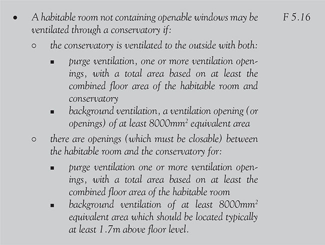

Figure 6.11.5 Ventilation through a conservatory
6.11.2.4.3 Dimensions of windows

![]() Note: Approved Document B includes provisions for the size of escape windows where the requirements differ the larger of the provisions in Approved Document B or F should apply in all cases.
Note: Approved Document B includes provisions for the size of escape windows where the requirements differ the larger of the provisions in Approved Document B or F should apply in all cases.

Figure 6.11.6 Window dimensions
p.722
6.11.2.4.4 Trickle ventilation

Table 6.11.1 Equivalent areas for replacement windows – dwellings

p.723
6.11.2.4.5 Purge ventilation

6.11.2.5 Drainage and waste disposal

p.724
6.11.2.6 Combustion appliances and fuel storage systems
6.11.2.6.1 Interaction of mechanical extract ventilation and open-flued combustion appliances
Extract fans lower the pressure in buildings which can cause the spillage of combustion products from open-flued appliances. Tests that show combustion appliances operate safely whether or not fans are running are required.
p.725

6.11.2.6.2 Carbon monoxide alarm location

p.726
6.11.2.6.3 Locations of flue outlets near windows


Figure 6.11.7 Location of outlets near roof windows from flues serving gas appliances
p.727
6.11.2.7 Protection from falling, collision and impact
6.11.2.7.1 Pedestrian guarding
Provision shall be made to prevent people moving in or about the building from colliding with open windows, skylights or ventilators.
p.728

6.11.2.7.2 Glazing in critical locations
p.729
![]() Note: For the purposes of this recommendation, a ‘small pane’ (see Figure 6.11.8) is an isolated pane or one of a number of panes held in glazing bars, traditional leaded lights or copper lights with the following dimensions:
Note: For the purposes of this recommendation, a ‘small pane’ (see Figure 6.11.8) is an isolated pane or one of a number of panes held in glazing bars, traditional leaded lights or copper lights with the following dimensions:
p.730
• the maximum area of the single pane should not exceed 0.5m2
• the maximum width is 250mm
• small panes of annealed glass should not be less than 6mm thick.

Figure 6.11.9 Dimensions and areas of small panes

p.731

Figure 6.11.10 Permanent screen protection
p.732
6.11.2.7 Conservation of fuel and power
![]() Since April 2014 all new homes (i.e. dwellings) need to achieve, or better, a fabric energy efficiency target in addition to the strengthened requirement to deliver 6 percent carbon dioxide savings.
Since April 2014 all new homes (i.e. dwellings) need to achieve, or better, a fabric energy efficiency target in addition to the strengthened requirement to deliver 6 percent carbon dioxide savings.
![]() Note: Regulation 25B (Nearly zero-energy requirements for new buildings) will not come into force until 2019 at the earliest and is therefore not covered in this edition.
Note: Regulation 25B (Nearly zero-energy requirements for new buildings) will not come into force until 2019 at the earliest and is therefore not covered in this edition.
p.733
6.11.2.8.1 Exemption from energy efficiency requirements

![]() Note: In these Regulations ‘thermal element’ does not include windows, roof windows or rooflights.
Note: In these Regulations ‘thermal element’ does not include windows, roof windows or rooflights.
![]() When restoring the character of a historic building that has been subject to previous inappropriate alteration (e.g. replacement windows) sympathetic treatment and advice from others could be very be beneficial.
When restoring the character of a historic building that has been subject to previous inappropriate alteration (e.g. replacement windows) sympathetic treatment and advice from others could be very be beneficial.
p.734
6.11.2.8.2 Limiting fabric standards

6.11.2.8.3 Solar gain

6.11.2.8.4 Thermal bridges

Alternative approaches for using linear transmittance are not mutually exclusive. For example, a builder could use approved design details for the majority of the junctions, but use a calculated bespoke detail for the window head.
p.735
6.11.2.8.5 Energy performance certificates
Regulation 7A of the Energy Performance of Buildings (England and Wales) Regulations 2012 requires that, when a dwelling is erected, the person carrying out the work must provide an energy performance certificate to the owner of the building as well as a notice to the BCB that a certificate has been given including the reference number under which the certificate has been registered. (See also the Energy Performance of Buildings (England and Wales) Regulations 2012 (SI 2012/3118) at www.legislation.gov.uk and detailed guidance on energy performance certificates at www.gov.uk).
![]() People who are responsible for building work (for example the agent, designer, builder or installer) must ensure that the work complies with all applicable requirements of the Building Regulations. But the building owner may also be responsible for ensuring that work complies with the Building Regulations. If building work does not comply with the Building Regulations, the building owner could well be served with an enforcement notice.
People who are responsible for building work (for example the agent, designer, builder or installer) must ensure that the work complies with all applicable requirements of the Building Regulations. But the building owner may also be responsible for ensuring that work complies with the Building Regulations. If building work does not comply with the Building Regulations, the building owner could well be served with an enforcement notice.
p.736
6.11.2.8.6 Controlled fittings
The application of the term controlled fitting to a window, roof window, or rooflight refers to a whole unit, including the frame. Consequently, replacing the glazing while retaining an existing frame is not providing a controlled fitting, and so such work is not notifiable and does not have to meet the Part L standards, although where practical it would be sensible to do so.


The U-values for roof windows and rooflights given in Approved Document L1B are based on the U-value of a roof window or rooflight in the vertical position. If a particular unit has been assessed in a plane other than the vertical, the standards given in this Approved Document should be modified by making an adjustment that is dependent on the slope.


p.737
6.11.2.8.7 Conservatories and porches


p.738
6.11.2.8.8 Extensions – area of windows

6.11.2.8.9 Consequential improvements

then in addition to the proposed building work (i.e. the principal works), consequential improvements will have to be completed, provided that they are technically, functionally and economically feasible. L1B 2.1
p.739
6.11.2.9 Access to and use of buildings
Approved Document M is all about making sure that when a new dwelling is being designed and built, reasonable provisions for most people (including wheelchair users and ambulant disabled people) have been included allow them to approach and enter the dwelling and to access habitable rooms and sanitary facilities on the entrance storey.
Sections 6.11.2.9.1 to 6.11.2.9.3 are optional requirements relating to windows for Accessible and adaptable dwellings M4(2) and wheelchair-user dwellings.
6.11.2.9.1 Habitable rooms – living, kitchen and eating areas

6.11.2.9.2 Bedrooms

6.11.2.9.3 Services and controls

6.11.2.10 Security – dwellings
![]() Note: Windows satisfying other standards that provide similar or better performance are also acceptable. These standards include:
Note: Windows satisfying other standards that provide similar or better performance are also acceptable. These standards include:
p.740
6.12.1 Requirements
6.12.2 Meeting the requirements
6.12.2.1 Fire safety
6.12.2.1.1 Building maintenance - provision of information

p.741
6.12.2.1.2 Alarms – smoke and heat alarms and detectors

p.742
6.12.2.1.3 Doors in compartment walls

p.743
6.12.2.1.4 Openings in cavity barriers

p.744
6.12.2.1.5 Vehicle access

6.12.2.1.6 Fire resistance

p.745

p.746
Table 6.12.1 Limitations on the used on uninsulated glazed elements on escape routes

All fire doors should be classified in accordance with BS EN 13501–2 and tested in accordance with BS EN 1634–1.
6.12.2.1.7 Fire doors in dwellings
Self-closing fire doors should be positioned so that smoke will not affect access to more than one stairway. The minimum fire resistance for doors in buildings other than dwellings is as given in Table 6.12.2. Glazing in any fire-resisting door should be fire-resisting and fixed shut.
p.747
BS 8214 gives recommendations for the specification, design, construction, installation and maintenance of fire doors constructed with non-metallic door leaves.
p.748
Guidance on timber fire-resisting doorsets may be found in Timber Fire-Resisting Doorsets: Maintaining Performance under the New European Test Standard, published by TRADA.
![]() Note: Unless pressurization techniques which comply with BS EN 12101–6 are used, fire doors should also either:
Note: Unless pressurization techniques which comply with BS EN 12101–6 are used, fire doors should also either:
• have a leakage rate not exceeding 3m3/m/hour (head and jambs only) when tested at 25 Pa under BS; or
• meet the additional classification requirement of Sa when tested to BS EN 1634–3.
p.749
![]() Authors’ note: A classification of Sa is used for doors which require restricted smoke leakage at ambient temperatures.
Authors’ note: A classification of Sa is used for doors which require restricted smoke leakage at ambient temperatures.

p.750
• The door should enable the person escaping to reach a place free from danger of fire (e.g. a courtyard or back garden which is at least as deep as the dwelling is high – see Figure 6.12.1).
![]() Note: A room accessed only via an inner room (an inner-inner room) may be acceptable if not more than one door separates the room from an interlinked smoke alarm and none of the access rooms is a kitchen. B 2.8
Note: A room accessed only via an inner room (an inner-inner room) may be acceptable if not more than one door separates the room from an interlinked smoke alarm and none of the access rooms is a kitchen. B 2.8
![]() Note: Detailed guidance on door openings and fire doors is given in Appendix B of Approved Document B
Note: Detailed guidance on door openings and fire doors is given in Appendix B of Approved Document B
p.751

Figure 6.12.1 Ground and basement storey exit into an enclosed space
6.12.2.1.8 Fire-protected stairways

6.12.2.1.9 Basements
Owing to the risk that a single stairway may be blocked by smoke from a fire in the basement or ground storey:

6.12.2.1.10 Loft conversions

p.752
In an ‘open-plan’ arrangement, it may be possible to provide sprinkler protection to the open-plan area, in conjunction with a fire-resisting partition and door, in order to separate the ground floor from the upper storeys. This door should be so arranged to allow the occupants of the loft room to access an escape window at first floor level. Cooking facilities should be separated from the open-plan area with fire-resisting construction.
![]() If it is considered undesirable to replace existing doors (e.g. if they are of historical or architectural merit) it may be possible to retain the doors or upgrade them to an acceptable standard.
If it is considered undesirable to replace existing doors (e.g. if they are of historical or architectural merit) it may be possible to retain the doors or upgrade them to an acceptable standard.
6.12.2.1.11 Garages


Figure 6.12.2 Separation between garage and dwelling
p.753
• Except for kitchens, all habitable rooms in the upper storey(s) of a dwelling served by only one stair should have direct access to a protected stairway. B 2.7

![]() Note: A communicating door between rooms should be provided so that it is possible to gain access to the escape window without passing through the stair enclosure and (when fitted) manual call points for fire alarm systems should be adjacent to exit doors.
Note: A communicating door between rooms should be provided so that it is possible to gain access to the escape window without passing through the stair enclosure and (when fitted) manual call points for fire alarm systems should be adjacent to exit doors.
6.12.2.2 Site preparation and resistance to moisture
6.12.2.2.1 Cladding

6.12.2.2.2 Joints between doors and walls

p.754

6.12.2.2.3 External walls (resistance to surface condensation and mould growth)

6.12.2.3 Resistance to the passage of sound
6.12.2.3.1 Corridor walls and doors

6.12.2.3.2 Stair covering and independent ceiling with absorbent material

p.755
6.12.2.3.3 Lightweight doors
Lightweight doors with poor perimeter sealing provide a lower standard of sound insulation than walls. This will reduce the effective sound insulation of the internal wall. Ways of improving sound insulation include ensuring that there is good perimeter sealing or by using a doorset.

6.12.2.3.4 Tests for soundproofing

Although not specifically required in test reports, it may be useful to have a description of the building including dimensions and position of any doors in external walls.
6.12.2.4 Ventilation

p.756
![]() Note: If a room contains more than one external door (or a combination of at least one external door and at least one openable window), the areas of all the opening parts may be added together to achieve at least 1/20 of the floor area of the room.
Note: If a room contains more than one external door (or a combination of at least one external door and at least one openable window), the areas of all the opening parts may be added together to achieve at least 1/20 of the floor area of the room.
6.12.2.5 Sanitation, hot water safety and water efficiency

6.12.2.6 Drainage and waste disposal

6.12.2.7 Combustion appliances and fuel storage systems

6.12.2.7.1 Provisions where there is a risk of oil pollution

p.757
6.12.2.7.2 Air permeability testing

6.12.2.8 Protection from falling, collision and impact
6.12.2.8.1 Doors on landings
A landing may include part of the floor of the building and should be kept clear of permanent obstructions.

6.12.2.8.2 Glazing in critical locations
Impacts with glazing, particularly glazing in doors and door side panels can result in cutting and piercing injuries. For doors and door side panels, the risk is greatest for glazing between floor and shoulder level when near to door handles and push plates, especially when normal building movement causes doors to stick.

p.758

Figure 6.12.3 Cupboards opening on to a landing.

Figure 6.12.4 Landings next to doors in dwellings
p.759

Figure 6.12.5 Critical glazing locations in internal and external walls
6.12.2.8.3 Safe breakage

6.12.2.9 Conservation of fuel and power
6.12.2.9.1 Thermal bridges
The building fabric should be constructed so that there are no reasonably avoidable thermal bridges in the insulation layers caused by gaps within the various elements, at the joints between elements, and at the edges of elements, such as those around window and door openings.

p.760
6.12.2.9.2 Historic buildings
Particular issues relating to work in historic buildings which warrant sympathetic treatment. In this case advice from others could be beneficial. Particularly when restoring the historic character of a building that has been subject to previous inappropriate alteration, e.g. replacement doors.
6.12.2.9.3 Conservatories and porches.

6.12.2.9.4 Major renovation
Major renovation means the renovation of a building where more than 25 percent of the surface-area of the building envelope undergoes renovation.
6.12.2.9.5 Energy efficiency
Energy efficiency measures must be provided that limit the heat loss through the doors, etc. by suitable means of insulation.

p.761
6.12.2.6.5.1 CO2emission rate for the building
Responsibility for achieving compliance with the requirements of Approved Document L for the conservation of fuel and power rests with the main (or sub-) contractor, or a specialist firm directly engaged by a private client.
![]() The person responsible for achieving compliance should either provide a certificate himself or obtain a certificate from the subcontractor that commissioning has been successfully carried out. The certificate should be made available to the client and the BCB.
The person responsible for achieving compliance should either provide a certificate himself or obtain a certificate from the subcontractor that commissioning has been successfully carried out. The certificate should be made available to the client and the BCB.
6.12.2.9.6 Extensions
Effective thermal separation should be provided between the heated area in the existing dwelling (i.e. the walls, doors, and windows between the dwelling and the extension), should be insulated and draught proofed to at least the same extent as in the existing dwelling.

6.12.2.9.6.2 area of windows, roof windows and doors

p.762
6.12.2.9.6.3 whole dwelling calculation method

![]() Note: The data in SAP 2012 Appendix S can be used to estimate the performance of the elements of the existing building where these are unknown.
Note: The data in SAP 2012 Appendix S can be used to estimate the performance of the elements of the existing building where these are unknown.
![]() Removing, and not replacing, any or all of the thermal separation between the dwelling and an existing exempt extension, or extending the dwelling’s heating system into the extension, means the extension ceases to be exempt and should be treated as a conventional extension. If the total floor area of the proposed extension exceeds these limits, the work should be regarded as a new building and the requirements of Approved Documents L2A and L2B should be used.
Removing, and not replacing, any or all of the thermal separation between the dwelling and an existing exempt extension, or extending the dwelling’s heating system into the extension, means the extension ceases to be exempt and should be treated as a conventional extension. If the total floor area of the proposed extension exceeds these limits, the work should be regarded as a new building and the requirements of Approved Documents L2A and L2B should be used.

In addition, doors between the building and an extension should be insulated and weather-stripped to at least the same extent as in the existing building. To meet this requirement, it is recommended that you use construction joint details that have been calculated following the guidance set out in BRE Report BR 497.
p.763
6.12.2.9.7 Material change of use and change of energy status

6.12.2.9.8 Controlled fittings
The application of the term ‘controlled fitting’ to a door refers to the complete doorset (leaf plus frame) and so replacing a door leaf (while retaining the existing frame) is not notifiable and does not have to meet Approved Document L’s requirements – although where practical it would be sensible to do so!

Table 6.12.3 Standards for controlled fittings

p.764
When working on a controlled service or fitting (i.e. where the service or fitting is subject to the requirements of Approved Documents G, H, J, L or P), and where windows, roof windows, rooflights and/or doors are to be provided:

Table 6.12.4 Standards for thermal elements for new fittings in an extension

6.12.2.10 Access to and use of buildings
6.12.2.10.1 External ramps forming part of an approach route

6.12.2.10.2 Communal entrances
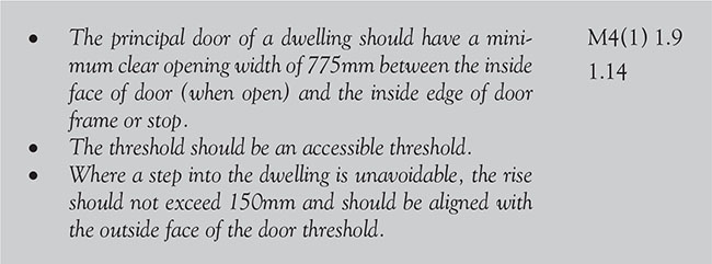
p.765

6.12.2.10.3 Circulation areas and internal doorways – door and hall widths

Table 6.12.2 Minimum widths of corridors and passageways for a range of door widths
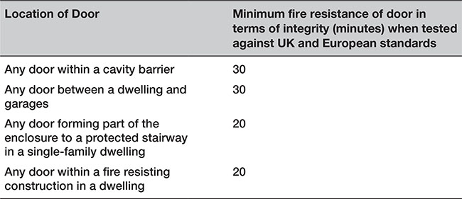
6.12.2.10.4 WC facilities

p.766
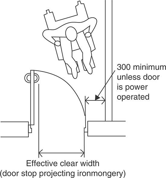
Figure 6.12.6 Measurement of clear opening width of external and internal doors
6.12.2.10.5 Approach route

6.12.2.10.6 Principal communal entrance

p.767

The following are additional requirements for wheelchair-accessible dwellings:
• A clear turning circle 1500mm in diameter should be provided inside the entrance area, behind the entrance door when closed.
• A minimum 200mm nib is provided to the following edge of the door (or gate) and the extra width created by this nib is maintained for a distance of a minimum 1800mm beyond it.
• The door is located reasonably centrally within the thickness of the wall while ensuring that the depth of the reveal on the leading face of the door (usually the inside) is a maximum of 200mm.
• Where power assisted opening is provided where the opening force of the door is more than 30 N ofthe opening cycle.
p.768
6.12.2.11 Electrical safety – dwellings
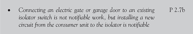
6.12.2.12 Security – dwellings
![]() Authors’ note: Approved Document Q is a new requirement for England and Wales and came into effect in October 2015.
Authors’ note: Approved Document Q is a new requirement for England and Wales and came into effect in October 2015.
6.12.2.12.1 General
All easily accessible doorsets (including garage doorsets and communal entrance doorsets) that provide access into a dwelling or into a building containing a dwelling should be secure doorsets in accordance with Approved Document paragraphs 1.2 to 1.4 shown below.
![]() Note: If a garage has no interconnecting doorset that allows access into the dwelling, the doorset need not be a secure doorset. Where access to the dwelling can be gained via an interconnecting doorset from the garage, then either the garage doorset (pedestrian and vehicular) or the interconnecting doorset should be a secure doorset.
Note: If a garage has no interconnecting doorset that allows access into the dwelling, the doorset need not be a secure doorset. Where access to the dwelling can be gained via an interconnecting doorset from the garage, then either the garage doorset (pedestrian and vehicular) or the interconnecting doorset should be a secure doorset.
6.12.2.12.2 Design of secure doorsets

p.769
![]() Note: In some situations, a door chain or limiter is not appropriate, for example where a warden may need emergency access to residents in sheltered housing. Alternative caller-identification measures, such as electronic audio-visual door entry systems, can be used to identify visitors.
Note: In some situations, a door chain or limiter is not appropriate, for example where a warden may need emergency access to residents in sheltered housing. Alternative caller-identification measures, such as electronic audio-visual door entry systems, can be used to identify visitors.
6.12.2.9.3 Installation and fixing of secure doorsets

p.770
6.13 Access routes to, from and within buildings
6.13.1 Requirements
p.771
![]() The guidance provided in the Approved Documents are in relation to the permanent features which form part of the building. There may situations, such as access for maintenance which are used less frequently where the provisions of the Construction (Design and Management) Regulations 2015 are more appropriate.
The guidance provided in the Approved Documents are in relation to the permanent features which form part of the building. There may situations, such as access for maintenance which are used less frequently where the provisions of the Construction (Design and Management) Regulations 2015 are more appropriate.
p.772
6.13.2 Meeting the requirements
p.773
6.13.2.1 Fire safety
The building shall be designed and constructed so as to provide reasonable facilities to assist firefighters in the protection of life and be constructed in a manner to enable fire appliances to gain access to the building.
p.774
6.13.2.1.1 Access for fire appliances and firefighters

![]() Note: It may not always be reasonable to upgrade an existing route across a site to a small building such as a single dwelling. The options in such a case, from doing no work to upgrading certain features of the route, e.g. a sharp bend, should be considered by the BCB in consultation with the fire and rescue service.
Note: It may not always be reasonable to upgrade an existing route across a site to a small building such as a single dwelling. The options in such a case, from doing no work to upgrading certain features of the route, e.g. a sharp bend, should be considered by the BCB in consultation with the fire and rescue service.
p.775

Figure 6.13.1 Turning facilities
Table 6.13.1 Typical fire and rescue vehicle access route specification

6.13.2.1.2 Means of escape

p.776

p.777
![]() Note: If it is considered undesirable to replace existing doors (e.g. if they are of historical or architectural merit), it may be possible to retain the doors or upgrade them to an acceptable standard.
Note: If it is considered undesirable to replace existing doors (e.g. if they are of historical or architectural merit), it may be possible to retain the doors or upgrade them to an acceptable standard.
Where an ‘open-plan’ arrangement exists at ground level, it may be necessary to provide a new partition to enclose the escape route. Alternatively, it may be possible to provide sprinkler protection to the open-plan area, in conjunction with a fire-resisting partition and door, in order to separate the ground floor from the upper storeys. This door should be so arranged to allow the occupants of the loft room to access an escape window at first floor in the event of a fire in the open-plan area. Cooking facilities should be separated from the open-plan area with fire-resisting construction.

Figure 6.13.2 Gallery floor with no alternative exit
![]() A room accessed only via an inner room (i.e. an inner-inner room) may be acceptable, if it complies with the above, provided that not more than one door separates the room from an interlinked smoke alarm and none of the access rooms is a kitchen.
A room accessed only via an inner room (i.e. an inner-inner room) may be acceptable, if it complies with the above, provided that not more than one door separates the room from an interlinked smoke alarm and none of the access rooms is a kitchen.
6.13.2.1.3 Lifts

p.778
6.13.2.2 Site preparation and resistance to contaminants and moisture
6.13.2.2.1 Site assessment

![]() Note: There may be a case for a lower remedy level if part of the land associated with the building is accessible to a lesser extent those in and about the building than the main parts of the buildings and their respective gardens.
Note: There may be a case for a lower remedy level if part of the land associated with the building is accessible to a lesser extent those in and about the building than the main parts of the buildings and their respective gardens.
6.13.2.2.2 Subsoil drains

6.13.2.2.3 Ventilated airspace

6.13.2.2.4 Accessible thresholds

6.13.2.3 Resistance to the passage of sound
6.13.2.3.1 Sets of tests in flats with a separating floor and a separating wall

p.779

Figure 6.13.3 Accessible threshold for use in exposed areas
6.13.2.3.2 Corridor walls and doors

![]() Additional absorption should to be used in corridors, hallways, stairwells and entrance halls that give access to flats and rooms for residential purposes.
Additional absorption should to be used in corridors, hallways, stairwells and entrance halls that give access to flats and rooms for residential purposes.
6.13.2.4 Ventilation
6.13.2.4.1 Live-work units

p.780

6.13.2.4.2 New dwellings

6.13.2.4.3 Access for maintenance

![]() Note: Where no special provision is required, the requirement could be satisfied if 600mm space is provided where access is required between plant. 1100mm should be provided where space for routine cleaning is required.
Note: Where no special provision is required, the requirement could be satisfied if 600mm space is provided where access is required between plant. 1100mm should be provided where space for routine cleaning is required.
6.13.2.4.4 Ventilation controls

6.13.2.5 Sanitation, hot water safety and water efficiency
6.13.2.5.1 Design and installation of hot water storage systems

6.13.2.5.2 Sanitary conveniences and washing facilities
![]() Note: Attention is also drawn to the requirements for accessible sanitary conveniences and hand-washing facilities of Approved Document M (Access routes to, from and within buildings).
Note: Attention is also drawn to the requirements for accessible sanitary conveniences and hand-washing facilities of Approved Document M (Access routes to, from and within buildings).
p.781
6.13.2.5.2 Scale of provision and layout in dwellings

![]() Note: In dwellings, a room containing both a sanitary convenience and a basin for hand washing does not need a separation lobby between this room and a kitchen or food preparation area. The layout for a room containing a sanitary convenience only should be such that the room or space containing its associated hand-washing facilities is accessed before entry to a food preparation area, and is separated from that area by a door.
Note: In dwellings, a room containing both a sanitary convenience and a basin for hand washing does not need a separation lobby between this room and a kitchen or food preparation area. The layout for a room containing a sanitary convenience only should be such that the room or space containing its associated hand-washing facilities is accessed before entry to a food preparation area, and is separated from that area by a door.
6.13.2.5.3 Discharges to drain

6.13.2.6 Drainage and waste disposal
6.13.2.6.1 Foul water drainage – access for clearing blockages.

p.782

6.13.2.6.2 Septic tanks

This distance may need to be reduced where the depth to the invert of the tank is more than 3m. There should also be a clear route for the hose such that the tank can be emptied and cleaned without hazard to the building occupants and without the contents being taken through a dwelling or place of work.

6.13.2.6.3 Sanitary pipework

p.783
6.13.2.6.4 Cesspools siting

6.13.2.6.5 Greywater and rainwater storage tank

6.13.2.6.6 Special protection – rodent control
6.13.2.6.7 Clearance of blockage

p.784

![]() Note: If you repair, reconstruct or alter a drain you MUST give free access to the Local Authority to inspect the works.
Note: If you repair, reconstruct or alter a drain you MUST give free access to the Local Authority to inspect the works.
p.785
6.13.2.6.8 Sealing disused drains
Drains or sewers less than 1.5m deep which are in open ground should as far as is practicable be removed. Other pipes should be sealed at both ends and at any point of connection, and grout-filled to ensure that rats cannot gain access.
6.13.2.6.9 Rainwater drainage

6.13.2.6.10 Refuse storage

6.13.2.6.11 Building over sewers

6.13.2.6.12 Maintaining access

p.786

6.13.2.6.13 Solid waste storage

6.13.2.7 Combustion appliances and fuel storage systems
6.13.2.7.1 Metal chimney and flues
p.787


Figure 6.13.4 Example locations of access panels for concealed horizontal flues
p.788
6.13.2.7.2 Configuration of natural draught flues serving open-flued
Flue systems should offer least resistance to the passage of flue gases by minimizing changes in direction or horizontal length.

![]() Note: A way of doing this would be to limit the number of changes of direction between the combustion appliance outlet and the flue outlet to not more than four (each up to 45°), not more than two of these being between an intended point of access for sweeping and either another point of access for sweeping or the flue outlet. (90° factory-made bends, elbows or T-pieces in fluepipes may be treated as being equal to two 45° bends.)
Note: A way of doing this would be to limit the number of changes of direction between the combustion appliance outlet and the flue outlet to not more than four (each up to 45°), not more than two of these being between an intended point of access for sweeping and either another point of access for sweeping or the flue outlet. (90° factory-made bends, elbows or T-pieces in fluepipes may be treated as being equal to two 45° bends.)
6.13.2.7.3. Inspection and cleaning openings in flues

6.13.2.7.4. Access to combustion appliances for maintenance

6.13.2.7.5 Debris collection space

This can be achieved by providing a space having a volume of not less than 12 litres and a depth of at least 250mm below the point where flue gases discharge into the chimney. The space should be readily accessible for clearance of debris, for example by removal of the appliance.
p.789
6.13.2.7.6 Location and support of cylinders

6.13.2.8 Protection from falling, collision and impact
6.13.2.8.1 Access routes – hazards


Figure 6.13.5 Avoiding doors on access routes
p.790
6.13.2.8.2 Access stairs


Figure 6.13.6 Tread nosing profiles
6.13.2.8.3 Alternating tread stairs in dwellings

6.13.2.8.4 Protection against impact from and trapping by doors

p.791
6.13.2.8.5 Access routes guarding
For common access areas of buildings that contain flats:

6.13.2.8.6 Pedestrian guarding
Guarding should be provided whenever it is considered necessary from the point of view of safety to guard:

![]() Note: Guarding is not required on ramps that are used only for vehicle access or in places such as loading bays where it would obstruct normal use.
Note: Guarding is not required on ramps that are used only for vehicle access or in places such as loading bays where it would obstruct normal use.
6.13.2.8.7 Balcony guarding
If a balcony or flat roof is provided for escape purposes (or whenever it is considered necessary from a safety point of view) guarding should be provided to guard the edges of any part of a floor (including the edge below an opening window) of a gallery or balcony (and any other openings), and any other place to which people have access.
![]() Note: Guarding is not required in places such as loading bays where it would obstruct normal use.
Note: Guarding is not required in places such as loading bays where it would obstruct normal use.
p.792
6.13.2.8.8 Access routes – handrails for stairs


Figure 6.13.7 Handrail design
6.13.2.8.9 Access routes – width of ramps
In dwellings and common access areas in buildings that contain flats with ramps that are:

![]() Note: Handrails should give firm suppo rt and allow a firm grip and may form the top of the guarding.
Note: Handrails should give firm suppo rt and allow a firm grip and may form the top of the guarding.
p.793
6.13.2.8.10 Access – vehicles
For all buildings:


Figure 6.13.8 Barrier siting – all buildings
![]() Note: Where parts of windows, skylights and ventilators project inside or outside a building on an access route a suitable barrier should be provided.
Note: Where parts of windows, skylights and ventilators project inside or outside a building on an access route a suitable barrier should be provided.
6.13.2.8.11 Access for maintenance
Where the stairs or ladders will be used to access areas for maintenance they should comply with the provisions of BS 5395–3 and the Construction (Design and Management) Regulations 2015 as appropriate.
6.13.2.8.12 Access for cleaning windows, etc.
Where a person standing on a permanent stable surface cannot safely clean a glazed surface:

p.794

Figure 6.13.9 Safe reaches for cleaning

![]() If none of the above alternatives is possible, then scaffolding towers (portable or fixed) will have to be used.
If none of the above alternatives is possible, then scaffolding towers (portable or fixed) will have to be used.
6.13.2.8.13 Access between levels – all buildings

6.13.2.8.14 Means of escape
In dwellings, a fixed ladder may be used – with fixed handrails on both sides – for access in a loft conversion that contains one habitable room.
![]() Retractable ladders may not be used as means of escape.
Retractable ladders may not be used as means of escape.
p.795

Figure 6.13.10 Minimum headroom on access routes
6.13.2.9 Access to and use of buildings
![]() Note: In 2016, Approved Document M was updated and now the only compulsory requirement dealing with access for dwellings is contained in Requirement M4(1). Requirements M4(2) Accessible and adaptable dwellings and M4(3) Category 3 Wheelchair user dwellings are optional requirements for dwellings and only apply of the owner of the property desires this to be the case.
Note: In 2016, Approved Document M was updated and now the only compulsory requirement dealing with access for dwellings is contained in Requirement M4(1). Requirements M4(2) Accessible and adaptable dwellings and M4(3) Category 3 Wheelchair user dwellings are optional requirements for dwellings and only apply of the owner of the property desires this to be the case.
6.13.2.9.1 New dwellings

p.796

![]() Requirements for accessibility should be balanced against preserving historic buildings or environments. In achieving an appropriate balance, it would be appropriate to take into account the advice of the Local Authority’s conservation and access officers, English Heritage and the views of local access groups.
Requirements for accessibility should be balanced against preserving historic buildings or environments. In achieving an appropriate balance, it would be appropriate to take into account the advice of the Local Authority’s conservation and access officers, English Heritage and the views of local access groups.
6.13.2.9.2 Approach to a dwelling

p.797

p.798
6.13.2.9.3 Entrances
The principal communal entrance door of the building containing the dwelling should comply with all of the following:

![]() For private entrances where a step into the dwelling is unavoidable, the rise is a maximum 150mm and is aligned with the outside face of the door threshold.
For private entrances where a step into the dwelling is unavoidable, the rise is a maximum 150mm and is aligned with the outside face of the door threshold.
6.13.2.9.4 Communal lifts and stairs

p.799

Figure 6.13.11 Key dimensions associated with passenger lifts (mm)
6.13.2.9.5 Communal stairs

6.13.2.9.6 Door and hall widths

p.800

Figure 6.13.12 Minimum door width, hall width and localised obstructions
6.13.2.9.7 Private stairs and changes of level within the entrance storey

Table 6.13.2 Minimum widths of corridors and passageways for a range of door widths

p.801

Figure 6.13.13 WC access zones
6.15.2.9.2 Provision for accessible and wheelchair-adaptable dwellings
The provision of dwellings that are accessible and/or wheelchair adaptable is an optional requirement. The following is a summary of the main areas you should consider if you wish to go down this route.
Table 6.13.3 Requirements specific to Optional Requirements M4(2) and M4(3)
p.802
6.14 Corridors and passageways
6.14.1 Requirements

p.803

![]() Amendments to Approved Document M came into force in 2015 with a further revision in 2016.
Amendments to Approved Document M came into force in 2015 with a further revision in 2016.
6.14.2 Meeting the requirements
6.14.2.1 Fire safety
6.14.2.1.1 Unprotected and protected escape routes
The unprotected part of an escape route is that part which a person has to traverse before reaching either the safety of a final exit or the comparative safety of a protected escape route, i.e. a protected corridor or protected stairway.
p.804
6.14.2.2 Site preparation and resistance to contaminants and moisture

6.14.2.3 Resistance to the passage of sound
6.14.2.3.1 Sound insulation testing

6.14.2.3.2 Corridor walls
The separating walls described in this section should be used between corridors and rooms in flats, in order to control flanking transmission and to provide the required sound insulation. However, it is likely that the sound insulation will be reduced by the presence of a door.

![]() Sound insulation will be reduced by the presence of a door.
Sound insulation will be reduced by the presence of a door.
p.805

![]() Note:
Note:
1. Wall types 2 and 4 can be used provided that care is taken to maintain isolation between the leaves. Specialist advice may, however, be required.
2. Noisy parts of the building should preferably have a lobby, double door or high performance doorset to contain the noise.
6.14.2.3.3 Reverberation in the common internal parts of buildings
When an entrance hall, corridor, hallway or stairwell provides access to flats and rooms used for residential purposes, the following guidance should be used followed for each space.

p.806

Method B is intended only for corridors, hallways and entrance halls as it is not well suited to stairwells.
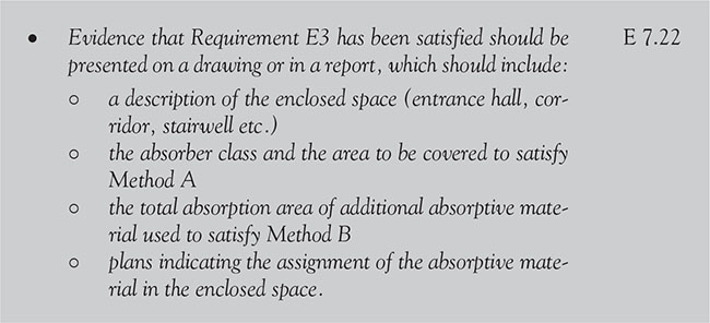
![]() Note: This method is described in detail in Section 7 of Approved Document E.
Note: This method is described in detail in Section 7 of Approved Document E.
6.14.2.4 Protection from falling collision and impact
6.14.2.4.1 Permanent methods to indicate glazing, and alternative methods

p.807


Figure 6.14.1 Height of manifestation for glass doors and glazed screens
6.14.2.5 Access to and use of buildings
6.14.2.5.1 Door and hall width
In all dwellings to facilitate access into habitable rooms and to a WC in the entrance storey, door and hall widths should comply with Figure 6.14.2 and take note of the following guidance:

p.808

Table 6.14.1 Minimum widths of corridors and passageways for a range of door widths


Figure 6.14.2 Minimum door width, hall widths and localised obstructions
6.14.2.5.2 Approach to the dwelling
For a house (or other dwelling that sits within its own plot), the approach route will often only involve a driveway, or a gate and a path, but for a dwelling within a larger building (typically a block of flats) the approach route will usually involve one or more communal gates, paths, entrances, doors, lobbies, corridors and access decks, as well as communal lifts and stairs.
For an accessible or adaptable dwellings using Approved Document M4(2) doors and corridors should comply with Figure 6.14.3. To facilitate movement into, and between, rooms throughout the dwelling and take note of the following requirements:
p.809

![]() Note: M4(2) is an optional requirement for accessible and adaptable dwellings.
Note: M4(2) is an optional requirement for accessible and adaptable dwellings.

Figure 6.14.3 Minimum door and hall widths and restrictions on localised obstructions
6.14.2.6 Electrical safety
6.14.2.6.1 Scope

p.810
6.15 Sanitary accommodation, bathrooms and showers
6.15.1 Requirements

p.811

p.812

p.813
![]() Amendments to Approved Document M came into force in 2015 with a further revision in 2016.
Amendments to Approved Document M came into force in 2015 with a further revision in 2016.
6.15.2 Meeting the requirements
All buildings (except factories and buildings used as workplaces) shall be provided with sufficient closet (or privy) accommodation according to the intended use of that building and the amount of people using that building. The only exceptions are if the building (in the view of the local authority) has an insufficient water supply and a sewer is not available.
6.15.2.1 Fire safety
6.15.2.1.1 Smoke alarms

6.15.2.1.2 Inner rooms

6.15.2.1.3 Protection of openings for pipes

p.814

Figure 6.15.1 Pipes penetrating a structure

6.15.2.2 Site preparation and resistance to moisture
6.15.2.2.1 Spillage
In bathrooms where water may be spilled, any board used as a flooring, irrespective of the storey, should be moisture resistant.

6.15.2.2.2 Roofs - resistance to damage from interstitial condensation

p.815
6.15.2.2.3 Subsoil drainage

6.15.2.3 Resistance to the passage of sound
6.15.2.3.1 Junctions with floor penetrations
Fire-stopping should be flexible and prevent rigid contact between the pipe and floor.
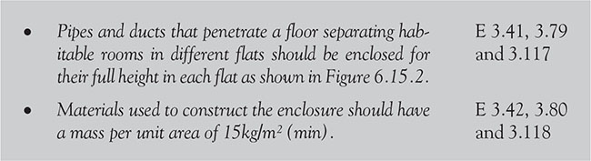
![]() Note: Enclosure can either lined or the duct (or pipe) within the enclosure can be wrapped with 25mm unfaced mineral fibre.
Note: Enclosure can either lined or the duct (or pipe) within the enclosure can be wrapped with 25mm unfaced mineral fibre.

Figure 6.15.2 Floor type 1 – floor penetrations.
p.816
6.15.2.3.2 Dwellings and flats formed by a material change of use

6.15.2.4 Ventilation
6.15.2.4.1 Minor works

6.15.2.4.2 Performance of ventilation system

p.817

6.15.2.4.3 Control of the ventilation system

![]() Note:
Note:
1. Humidity control is not appropriate for sanitary accommodation, where the dominant pollutant is normally odour.
2. Trickle ventilators are available which ‘throttle down’ the ventilation flow passage(s) according to the pressure difference across the ventilator to reduce draught risks during windy weather.
3. Manufacturers should be consulted when selecting the correct type of pressure-controlled trickle ventilator.
6.15.2.4.4 Noise
Noise generated by ventilation fans may disturb the occupants of the building and so discourage their use. The designer should, therefore, consider minimizing noise by careful design and by specifying a quieter product. To ensure good acoustic conditions, the average A-weighted sound pressure level in noise sensitive rooms, such as bedrooms and living rooms, should not exceed 30dB LAeq,T. In less sensitive rooms, such as kitchens and bathrooms, a higher level would be acceptable, e.g. 35dB LAeq,T.
p.818
![]() Noise from a continuously running mechanical ventilation system on its minimum low rate should not normally exceed these levels and should preferably be lower.
Noise from a continuously running mechanical ventilation system on its minimum low rate should not normally exceed these levels and should preferably be lower.
6.15.2.4.5 Extract ventilation
Extract ventilation concerns the removal of air directly from a space or spaces to outside. Extract ventilation may be by natural means such as Passive Stack Ventilation (PSV) or by mechanical means (e.g. by an extract fan).

Table 6.15.1 Extract ventilation rates – sanitary accommodation

6.15.2.4.6 Purge ventilation

p.819
![]() Note: Manual boost controls should be provided locally to the spaces being served
Note: Manual boost controls should be provided locally to the spaces being served
Table 6.15.2 Passive Stack Ventilation – sanitary accommodation

6.15.2.5 Sanitation, hot water safety and water efficiency
6.15.2.5.1 Provision of hot water supply

![]() Note: Guidance on the use of in-line blending valves can be found in BRE Information paper IP14/03.
Note: Guidance on the use of in-line blending valves can be found in BRE Information paper IP14/03.
6.15.2.5.2 Bathrooms

6.15.2.5.3 Sanitary conveniences
Sanitary conveniences of an appropriate type for the sex and age of the persons using the building shall be provided in sufficient numbers. Hand-washing facilities shall be provided in, or adjacent to, rooms containing sanitary conveniences.
![]() Guidance on the selection, installation and maintenance of sanitary appliances including composting toilets may be found in BS 6465–3.
Guidance on the selection, installation and maintenance of sanitary appliances including composting toilets may be found in BS 6465–3.
p.820

![]() Note:
Note:
1. Any system/unit used to supply dwellings with water from alternative sources should be subject to a risk assessment by the system designer and the manufacturer.
2. A record of all sanitary appliances used in the water consumption calculation and installed in the dwelling shall be maintained.
6.15.2.5.4 Sanitary appliances
The manner in which sanitary appliances and white goods are identified and used in the design calculation shall be provided and installed in the dwelling.

p.821

6.15.2.5.5 Discharge pipes

6.15.2.5.6 Prevention of scalding

![]() We think that this is because most people are right handed and it is to stop people (particularly children and poorly sighted people) inadvertently scalding themselves. To be on the safe side, therefore, it is recommended that, even though the requirement only applies to new buildings, you always ensure the hot water taps are located on the left-hand side of all of your basins and baths.
We think that this is because most people are right handed and it is to stop people (particularly children and poorly sighted people) inadvertently scalding themselves. To be on the safe side, therefore, it is recommended that, even though the requirement only applies to new buildings, you always ensure the hot water taps are located on the left-hand side of all of your basins and baths.

p.822
6.15.2.5.6 Scale of provision and layout in dwellings

![]() Note: Guidance on the provision of activity space around sanitary appliances is in BS 6465–2.
Note: Guidance on the provision of activity space around sanitary appliances is in BS 6465–2.

Figure 6.15.3 Separation between hand washbasin/WC and food preparation area – single room or two rooms
p.823
6.15.2.5.7 Chemical and composting toilets

p.824
6.15.2.5.8 Discharge to drains

6.15.2.6 Drainage and waste disposal
6.15.2.6.1 Flush volumes

p.825

6.15.2.6.1 Branch discharge pipes


Figure 6.15.4 Direct connection of ground floor WC to drain


p.826

Figure 6.15.5 Branch connections

Figure 6.15.6 Branch discharge stack
p.827

Figure 6.15.7 Stub stack

p.828
Table 6.15.3 Minimum trap sizes and seal depths

Table 6.15.4 Common branch discharge pipes (unventilated)

6.15.2.6.3 Ventilation of branch pipes
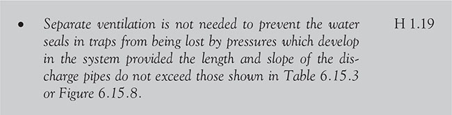
p.829

Figure 6.15.8 Branch connections stack

p.830

Figure 6.15.9 Branch ventilation pipes
6.15.2.6.4 Discharge stacks

p.831


Figure 6.15.10 Termination of ventilation stacks
Table 6.15.5 Minimum trap sizes and seal depths

p.832
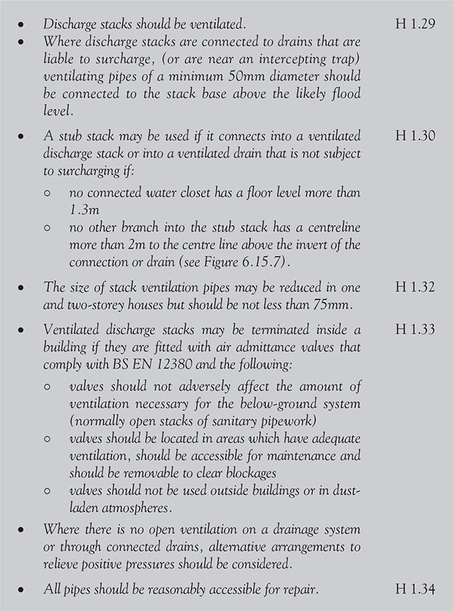
6.15.2.6.5 Materials for sanitary pipes fittings and joints

p.833
6.15.2.6.6 Foul drainage
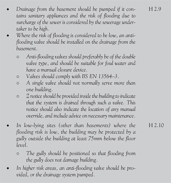
6.15.2.6.7 Pipe gradients and sizes

p.834

Table 6.15.6 Flow rates from dwellings

Table 6.15.7 Recommended minimum gradients for foul drains

6.15.2.6.8 Greywater recovery systems

![]() Note: Further guidance on greywater recovery systems can be found in the Water Regulations Advisory Scheme Leaflet No. 09-02-04, Reclaimed Water Systems. Information about installing, modifying or maintaining reclaimed water systems.
Note: Further guidance on greywater recovery systems can be found in the Water Regulations Advisory Scheme Leaflet No. 09-02-04, Reclaimed Water Systems. Information about installing, modifying or maintaining reclaimed water systems.
p.835
6.15.2.7 Combustion appliances and fuel storage systems
6.15.2.7.1 Location of outlets from flues

6.15.2.7.2 Appliances fitted in bathrooms
![]() Any appliance installed in a room that is used (or intended to be used) as a bathroom must be of the room-sealed type.
Any appliance installed in a room that is used (or intended to be used) as a bathroom must be of the room-sealed type.

![]() Bathrooms (and for that matter WCs or showers) that are situated less than 4.5m above ground level and whose only escape route is through another room shall be provided with an emergency egress window.
Bathrooms (and for that matter WCs or showers) that are situated less than 4.5m above ground level and whose only escape route is through another room shall be provided with an emergency egress window.
![]() Smoke alarms should not be fixed in bathrooms.
Smoke alarms should not be fixed in bathrooms.
6.15.2.8 Protection from falling, collision and impact
6.15.2.8.1 Alternating tread stairs

6.15.2.9 Access and use of buildings
6.15.2.9.1 WC facilities
Wherever possible the entrance storey should contain WC facilities. Where this is not possible, the stairs from the entrance storey to the storey above or below (whichever contains the bathroom) should be wide enough for a stair-lift to be fitted.
p.836

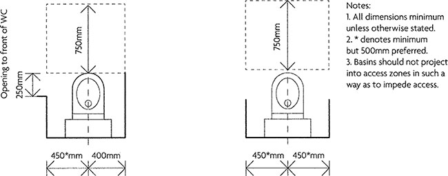
Figure 6.15.11 WC access zones
Table 6.15.8 Minimum widths of corridors and passageways for a range of door widths

![]() Note: The requirement does not apply to en-suite bathrooms or showers that are additional to the provision for a WC on the entrance storey.
Note: The requirement does not apply to en-suite bathrooms or showers that are additional to the provision for a WC on the entrance storey.
p.837
6.15.2.9.2 Provision for accessible and wheelchair-adaptable bathrooms
The provision of WC and sanitary facilities that are accessible and/or wheelchair-adaptable is an optional requirement. The following is a summary of the main areas you should consider if you wish to go down this route.

p.838
6.15.2.10 electrical safety
6.15.2.10.1 Notifiable work


Figure 6.16.12 Notifiable work in rooms containing a bath or a shower.
6.16 Electrical safety – dwellings
6.1.6.1 Requirements
![]() All electrical work shall be carried out in accordance with Amendment No. 3 (2015) to BS 7671 (Requirements for Electrical Installations, commonly referred to as the IEE Wiring Regulations, 17th edition).
All electrical work shall be carried out in accordance with Amendment No. 3 (2015) to BS 7671 (Requirements for Electrical Installations, commonly referred to as the IEE Wiring Regulations, 17th edition).
p.839

![]() Note: Although the main requirements for electrical safety are contained in Approved Document P, other associated requirements are scattered throughout the other Approved Documents and these are noted in the text below.
Note: Although the main requirements for electrical safety are contained in Approved Document P, other associated requirements are scattered throughout the other Approved Documents and these are noted in the text below.
The 2006 version of Approved Document P duplicated much of that contained in BS 7671. This standard had been developed from the Institution of Engineering Technology (IET)’s Wiring Regulations, which were first implemented in 1882 ‘for the prevention of fire risks from electric lighting’. With the upgrade of this standard in 2008, and further amendments in 2011, 2013 and 2015, it was decided that, rather than having two documents regulating the same thing, in future all electrical requirements and recommendations for the built environment would use BS 7671 (incorporating Amendment No. 3) and Approved Document P would only apply to electrical installations that are intended to operate at low or extra-low voltage and are:
p.840
• in or attached to a dwelling
• in the common parts of a building serving one or more dwellings, but excluding power supplies to lifts
• in a building that receives its electricity from a source located within or shared with a dwelling; or
• in a garden or in or on land associated with a building where the electricity is from a source located within or shared with a dwelling
and which are designed and installed so that:
• they afford appropriate protection against mechanical and thermal damage; and
• they do not present electric shock and fire hazards to people.
Main changes to the 2013 version of Approved Document P
Changes in the legal requirements:
• The range of electrical installation work that is notifiable has been reduced.
• An installer who is not a registered competent person may use a registered third party to certify notifiable electrical installation work as an alternative to using a Building Control Body (BCB).
• All electrical installation work must now fully comply with the requirements of BS 7671 (incorporating Amendment No. 2).
Additional changes as a result of Amendment No. 3 to BS 7671
Potentially life-saving changes have been made to the previous publication, making this a vital update. These changes include (but are not limited to) amendments in the following areas:
• consumer units
• wiring in escape routes
• earth fault loop impedances for all protective devices
• updated EIC and EICR forms
• definitions throughout the Regulations.
![]() Note: The latest edition of this standard has now grown to a massive 489-page document that defines the way in which all electrical installation work must be carried out. It does not matter whether the work is carried out by a professional electrician or an unqualified DIY enthusiast, but the installation must still totally comply with the Wiring Regulations.
Note: The latest edition of this standard has now grown to a massive 489-page document that defines the way in which all electrical installation work must be carried out. It does not matter whether the work is carried out by a professional electrician or an unqualified DIY enthusiast, but the installation must still totally comply with the Wiring Regulations.
These regulations form the basis of safe working practice throughout the electrical industry, but although BS 7671 is well structured and has separate sections for all the main topics (e.g. safety protection, selection and erection of equipment and so on), it is not the easiest of standards to get to grips with for a particular situation. Occasionally, it can be very confusing and requires the reader to constantly flick backwards and forwards through the book to find the information they are looking for.
p.841
![]() For your assistance, one of Ray Tricker’s other ‘In Brief’ books (Wiring Regulations in Brief, 3rd edition) is available from the publisher (www.routledge.com/Wiring-Regulations-in-Brief/Tricker/p/book/9780415526876) or other booksellers.
For your assistance, one of Ray Tricker’s other ‘In Brief’ books (Wiring Regulations in Brief, 3rd edition) is available from the publisher (www.routledge.com/Wiring-Regulations-in-Brief/Tricker/p/book/9780415526876) or other booksellers.
Figure 6.16.1 BS 7671 – 2008 Amendment N03
The intention of this book (similar to that of Ray Tricker’s other ‘In Brief’ books) is to peel away some of the confusion and ‘officialese’ and provide the reader with an on-the-job reference source that can be quickly used without having to delve into the standard.
6.1.6.2 Meeting the requirements
6.1.6.2.1 Fire safety
6.1.6.2.1.1 Smoke alarms
The installation of smoke alarms, or automatic fire detection and alarm systems, can significantly increase the level of safety by automatically giving an early warning of fire.
All new dwellings should be provided with a fire detection and fire alarm system in accordance with the relevant recommendations of BS 5839–6 to at least a Grade D Category LD3 standard.
p.842
![]() Note: If a dwelling is extended, smoke alarms should be provided in all circulation spaces.
Note: If a dwelling is extended, smoke alarms should be provided in all circulation spaces.

p.843

Figure 6.16.2 Typical fixed installations that might be encountered in new or upgraded existing dwellings
p.844

If more than one alarm is installed, the alarms should be linked so that the detection of smoke or heat by one unit operates the alarm signal in all of them. Smoke alarms/detectors should be sited so that:
6.1.6.2.1.2 Protection of openings and fire-stopping

p.845

6.1.6.2.1.3 Smoke alarms in thatched roofs
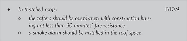
6.1.6.2.1.4 Material alterations

6.1.6.2.1.5 Sheltered housing

6.1.6.2.2 Site preparation and resistance to contaminants and moisture
6.1.6.2.2.1 Roofs (resistance to damage from interstitial condensation)

p.846

6.1.6.2.3 Resistance to the passage of sound
6.1.6.2.3.1 Ceiling treatments
![]() Note: Installing recessed light fittings in ceiling treatments can reduce their resistance to the passage of airborne and impact sound.
Note: Installing recessed light fittings in ceiling treatments can reduce their resistance to the passage of airborne and impact sound.
6.16.2.4 Sanitation, hot water safety and water efficiency
6.16.2.4.1 General

6.16.2.4.2 Water safety devices
Water safety devices normally consist of:
• non-self-resetting energy cut-outs
• temperature and pressure relief devices.
6.16.2.4.2.1 non-self-resetting energy cutouts

p.847
Where a non-self-resetting energy cut-out operates indirectly on another device to interrupt the supply of heat the energy cut-out should comply with the relevant European Standard or the supplier or installer should be able to demonstrate that the device has equivalent performance to that set out in relevant standards.
Where an electrical device, such as a relay or motorized valve, is connected to the energy cut-out, the device should operate to interrupt the supply of energy if the electrical power supply is disconnected.
Where there is more than one energy cut-out, each non-self-resetting energy cut-out should be independent and have a separate motorized valve and a separate temperature sensor.
Where an energy cut-out is fitted, each heat source should have a separate non-self-resetting energy cut-out.
6.16.2.4.2.2 temperature and pressure relief devices

![]() In such cases, there should be a second non-self-resetting energy cut-out independent of the one provided.
In such cases, there should be a second non-self-resetting energy cut-out independent of the one provided.

p.848

![]() Note: If the installer is registered with a competent person scheme for the installation of unvented hot water systems it will not be necessary for the work to be notified in advance to the BCB.
Note: If the installer is registered with a competent person scheme for the installation of unvented hot water systems it will not be necessary for the work to be notified in advance to the BCB.
Fixed building services, including controls, should be commissioned by testing and adjusting as necessary to ensure that they use no more fuel and power than is reasonable in the circumstances.
6.16.2.4.3 Electric water heating

6.16.2.4.4 Solar water heating

p.849
As some solar hot water systems operate at high temperatures and pressures, all components should be rated to the appropriate temperatures and pressures.
6.16.2.5 Drainage and waste disposal
6.16.2.5.1 Materials for pipes fittings and joints

6.16.2.6 Combustion appliances and fuel storage systems
6.16.2.6.1 Cellars or basements

6.16.2.7 Protection from falling, collision and impact
6.16.2.7.1 Safe opening and closing of windows - location of controls

6.16.2.7.2 Power-operated doors

p.850
6.16.2.8 Conservation of fuel and power
6.16.2.8.1 Controlled services

6.16.2.8.2 Commissioning of fixed building services
![]() Not all fixed building services will need to be commissioned. Examples of this would be some mechanical extraction systems or single fixed electrical heaters.
Not all fixed building services will need to be commissioned. Examples of this would be some mechanical extraction systems or single fixed electrical heaters.
6.16.2.9 Access to and use of buildings
6.16.2.9.1 Services and controls


Figure 6.16.3 Heights of switches and sockets
p.851

6.16.2.9.2 Communal entrances

6.16.2.9.3 Private entrances

6.16.2.9.4 Wheelchair storage and transfer areas
To enable a person to charge and store up to two wheelchairs and transfer between an outdoor and an indoor wheelchair, a dwelling should have a storage and transfer space.


Figure 6.16.4 Wheelchair storage and transfer space
p.852
6.16.2.9.5 Through-floor lifting device provision
Where the dwelling is defined as wheelchair-accessible, a suitable through-floor lift or lifting platform should be installed and commissioned. The following electrical inputs are required:

![]() Note: In a two-storey dwelling, the requirement can typically be met by a home lift to BS 5900 or lifting platforms to BS EN 81–41. However, a lifting platform may require a larger liftway than stated in paragraph 3.29 and may also require a three-phase power supply.
Note: In a two-storey dwelling, the requirement can typically be met by a home lift to BS 5900 or lifting platforms to BS EN 81–41. However, a lifting platform may require a larger liftway than stated in paragraph 3.29 and may also require a three-phase power supply.
6.16.2.9.6 Private stairs and changes of level within the dwelling
An ambulant disabled person should be able to move within, and between, storeys. It should also be possible to fit a stair-lift to the stairs from the entrance storey to the storey above (or the storey below) where this contains the bathroom.

6.16.2.9.7 Services and controls
To assist wheelchair users who have reduced reach, services and controls should comply with all of the following.
p.853

6.16.2.10 Electrical safety - Dwellings
6.16.2.10.1 Functionality requirements
Approved Document P of the Building Regulations covers the safety of electrical installation work; it does not cover system functionality. Other parts of the Building Regulations and other legislation cover the functionality of electrically powered products such as fire alarm systems, fans and pumps.
![]() It should be remembered that, while Approved Document P does not apply to electrical installations that supply the power for lifts in blocks of flats, it does apply to lift installations in single dwellings.
It should be remembered that, while Approved Document P does not apply to electrical installations that supply the power for lifts in blocks of flats, it does apply to lift installations in single dwellings.
p.854
![]() Note: Since the last edition of Building Regulations in Brief, the range of electrical installation work that is notifiable (where there is a requirement to certify compliance with the Building Regulations) has been reduced. An installer who is not a registered competent person may use a registered third party to certify notifiable electrical installation work as an alternative to using a BCB.
Note: Since the last edition of Building Regulations in Brief, the range of electrical installation work that is notifiable (where there is a requirement to certify compliance with the Building Regulations) has been reduced. An installer who is not a registered competent person may use a registered third party to certify notifiable electrical installation work as an alternative to using a BCB.
6.16.2.10.2 General
Low voltage and extra-low voltage electrical installations in dwellings are designed and installed so that both of the following conditions are satisfied:
• they afford appropriate protection against mechanical and thermal damage
• they do not present electric shock and fire hazards to people.

6.16.2.10.3 Provision of information

6.16.2.10.4 New dwellings

p.855
6.16.2.10.5 New dwellings formed by a change of use

![]() Although in some cases the existing electrical installation will need to be upgraded to meet current standards, if the existing cables are adequate it is not necessary to replace them, even if they use old colour codes.
Although in some cases the existing electrical installation will need to be upgraded to meet current standards, if the existing cables are adequate it is not necessary to replace them, even if they use old colour codes.
6.16.2.10.6 Additions and alterations to existing electrical installations
In accordance with the Building Regulations, when building work is complete, the building should be no more unsatisfactory in terms of complying with the applicable requirements of the Regulations than before the work was started.

p.856
6.16.2.10.7 Scope of Approved Document P


Figure 6.16.5 Scope of Approved Document P
p.857
6.16.2.10.8 Notifiable work
Electrical installation work that is notifiable is set out in Regulation 12(6A).

Figure 6.16.6 below illustrates the space around a bath tub or shower tray (a special location) within which minor additions and alterations to existing circuits, as well as the installation of new circuits, are notifiable.

Figure 6.16.6 Notifiable work in rooms containing a bath or a shower
p.858
![]() Note: Notifiable work involves activities (usually electrical) which should be notified by the installer to the Local Authority Building Control. If you are not sure whether the work you want to undertake is notifiable, you should contact your Local Authority Building Control Department for advice.
Note: Notifiable work involves activities (usually electrical) which should be notified by the installer to the Local Authority Building Control. If you are not sure whether the work you want to undertake is notifiable, you should contact your Local Authority Building Control Department for advice.
6.16.2.10.9 Non-notifiable work

6.16.2.10.10 Certifications, inspection and testing

p.859
![]() Note: Electrical inspection and test forms should be given to the person ordering the work. Building Regulations certificates should normally be given to the occupier.
Note: Electrical inspection and test forms should be given to the person ordering the work. Building Regulations certificates should normally be given to the occupier.
6.16.2.10.11 Self-certification by a registered competent person

6.16.2.10.12 Certification by a registered third party
![]() Note: The electrical installation condition report should be the model BS 7671 form or one developed specifically for Approved Document P purposes.
Note: The electrical installation condition report should be the model BS 7671 form or one developed specifically for Approved Document P purposes.
p.860
6.16.2.10.13 Certification by a Building Control Body

An installer who is competent to carry out inspection and testing should give the appropriate BS 7671 certificate to the BCB, which will take the certificate and the installer’s qualifications into account in deciding what further action, if any, it needs to take. BCBs may ask installers for evidence of their qualifications.
This can result in a lower Building Control charge as, when setting its charge, a Local Authority is required by the Building (Local Authority Charges) Regulations 2010 to take account of the amount of inspection work that it considers it will need to carry out.
Once the BCB has decided that, as far as can be ascertained, the work meets all Building Regulations requirements, it will issue to the occupier a Building Regulations completion certificate (if a Local Authority) or a final certificate (if an Approved Inspector).
6.16.2.10.14 Inspection and testing of non-notifiable work
6.16.2.10.15 Reports and certificates

p.861


Figure 6.16.7 Electrical installation certificate
p.862
6.16.2.10.16 Fixed internal lighting (domestic buildings)
In order that dwelling occupiers may benefit from the installation of efficient electric lighting, whenever:
p.863

Figure 6.16.8 Minor electrical installation certificate
• a dwelling is extended; or
• a new dwelling is created from a material change of use; or
• an existing lighting system has been replaced as part of rewiring works
the rewiring works must comply with BS 7671.
Lighting fittings (including lamp, control gear, housing, reflector, shade, diffuser or other device for controlling the output light) should only take lamps with a luminous efficiency greater than 40 lumens per circuit-watt.
p.864
![]() Note: Light fittings in less frequented areas such as cupboards and other storage areas do not count.
Note: Light fittings in less frequented areas such as cupboards and other storage areas do not count.
6.16.2.10.17 Fixed external lighting
Fixed external lighting (i.e. lighting that is fixed to an external surface of the dwelling and which is powered from the dwelling’s electrical system) should either:
• have a lamp capacity not exceeding 150W per light fitting that automatically switches off when there is enough daylight and when it is not required at night; or
• include sockets that can only be used with lamps which have an efficiency greater than 40 lumens per circuit-watt.
Fixed energy efficient light fittings (one per 25m2 dwelling floor area (excluding garages) and one per four fixed light fittings) should be installed in the most frequented locations in the dwelling.
External lighting (including lighting in porches, but not lighting in garages and car ports) should:
• automatically extinguish when there is enough daylight, and when not required at night
• have sockets that can only be used with lamps having an efficacy greater than 40 lumens per circuit-watt (such as fluorescent or compact fluorescent lamp types but not GLS tungsten lamps with bayonet cap or Edison screw bases).
6.16.2.10.18 Cables to outside buildings
Cables to an outside building (e.g. garage or shed):

p.865
![]() See BS 7671 or Wiring Regulations in Brief (3rd edition) by Ray Tricker for more information.
See BS 7671 or Wiring Regulations in Brief (3rd edition) by Ray Tricker for more information.
6.16.2.10.19 Where can I get more information?
Further guidance concerning the requirements for electrical safety is available from:
• the Institution of Engineering and Technology (IET) at www.theiet.org
• the National Inspection Council for Electrical Installation Contracting (NICEIC) at www.niceic.org.uk
• the Electrical Contractors’ Association (ECA) at www.niceic.org.uk or www.eca.co.uk
To download pdf copies of Approved Document P (and other Approved Documents), go to www.planningportal.gov.uk. For details of fixed wire colour changes, go to www.niceic.org.uk.
6.17. Requirements

p.866
p.867
6.17.2 Meeting the requirements
![]() Note: Any work associated with a combustion appliance is classed as notifiable building work. In these cases, it will be necessary to notify a BCB in advance of any work starting, unless work is carried out under a self-certification scheme or the work is repair or maintenance. Details of competent person’s schemes can be found at www.communities.gov.uk/planningandbuildingregulations/competentpersonsschemes.
Note: Any work associated with a combustion appliance is classed as notifiable building work. In these cases, it will be necessary to notify a BCB in advance of any work starting, unless work is carried out under a self-certification scheme or the work is repair or maintenance. Details of competent person’s schemes can be found at www.communities.gov.uk/planningandbuildingregulations/competentpersonsschemes.
For combustion appliances to continue to work safely and effectively, it is essential that they are adequately and regularly serviced and maintained.
6.17.2.1 Fire safety
![]() Connecting flue pipes and factory-made chimneys should always be guarded if there is a possibility of them being damaged or if they could present a burn hazard (that is not immediately apparent) for people.
Connecting flue pipes and factory-made chimneys should always be guarded if there is a possibility of them being damaged or if they could present a burn hazard (that is not immediately apparent) for people.


Figure 6.17.1 Flues penetrating compartment walls or floors
Combustion appliances require ventilation to supply them with air for combustion. Ventilation is also required to ensure the proper operation of flues or, in the case of flueless appliances, to ensure that the products of combustion are safely dispersed to the outside air.
p.868
6.17.2.2 Ventilation

![]() Note: The guidance provided with Approved Document F may not be adequate to address pollutants from flueless combustion space heaters or from occasional, occupant-controlled events such as painting, smoking, cleaning or other high-polluting activities.
Note: The guidance provided with Approved Document F may not be adequate to address pollutants from flueless combustion space heaters or from occasional, occupant-controlled events such as painting, smoking, cleaning or other high-polluting activities.
6.17.2.3 Combustion appliances and fuel storage systems
![]() Note: If internal mechanical ventilation is used to disperse ground gases, it may affect the functioning of combustion appliances and may lead to the spillage of products of combustion into the building.
Note: If internal mechanical ventilation is used to disperse ground gases, it may affect the functioning of combustion appliances and may lead to the spillage of products of combustion into the building.
6.17.2.3.1 Air supply for combustion installations
Combustion appliances need to be installed so that there is an adequate supply of air to them for combustion, to prevent overheating and for the efficient working of any flue.

p.869


Figure 6.17.2 Air for combustion and operation of the flue (open flued)
(a) Appliance in room
(b) Appliance in appliance compartment with internal vent
(c) Appliance in appliance compartment with external vent
![]() Where appliances are to be installed within balanced compartments, special provisions will be necessary.
Where appliances are to be installed within balanced compartments, special provisions will be necessary.
![]() Note: In a flueless situation, air for combustion (and to carry away its products) can be achieved as shown in Figure 6.17.4.
Note: In a flueless situation, air for combustion (and to carry away its products) can be achieved as shown in Figure 6.17.4.
p.870

Figure 6.17.3 Combustion and operation requiring air cooling

Figure 6.17.4 Air for combustion and operation of the flue (flueless)
If an appliance is room-sealed but takes its combustion air from another space in the building (e.g. the roof void), or if a flue has a permanent opening to another space in the building (e.g. where it feeds a secondary flue in the roof void), that space should have ventilation openings directly to outside.
p.871

![]() Note: Air vents for flueless appliances, however, should open directly to the outside air.
Note: Air vents for flueless appliances, however, should open directly to the outside air.
6.17.2.3.2 Air vents
Permanently open air vents should be non-adjustable, sized to admit sufficient air for the purpose intended, and positioned where they are unlikely to become blocked.


Figure 6.17.5 Examples of locations for permanent air vent openings
p.872

Figure 6.17.6 Air vent openings in a solid floor

Figure 6.17.7 Ventilator used in a roof space (e.g. a loft)
p.873
![]() In noisy areas, it may be necessary to install proprietary noise-attenuated ventilators to limit the entry of noise into the building.
In noisy areas, it may be necessary to install proprietary noise-attenuated ventilators to limit the entry of noise into the building.

![]() Note: Discomfort from cold draughts can be avoided by placing vents close to appliances (for instance, by using floor vents), by drawing air from intermediate spaces (such as from a hallway) or by placing air vents close to ceilings so as to ensure good mixing of incoming cold air.
Note: Discomfort from cold draughts can be avoided by placing vents close to appliances (for instance, by using floor vents), by drawing air from intermediate spaces (such as from a hallway) or by placing air vents close to ceilings so as to ensure good mixing of incoming cold air.
6.17.2.3.3 Flues
Appliances other than flueless appliances should incorporate or be connected to suitable flues which discharge to the outside air.

p.874

Figure 6.17.8 Measurement of flues and ducts
![]() Note: Chimneys and flues should provide satisfactory control of water condensation.
Note: Chimneys and flues should provide satisfactory control of water condensation.
6.17.2.3.4 Reuse of existing flues

![]() Note: A way of checking before and/or after remedial work would be to test the flue using the procedures in Appendix E of Approved Document J. Defective flues could then be relined using the materials and components described in Sections 2, 3, and 4 of Approved Document J.
Note: A way of checking before and/or after remedial work would be to test the flue using the procedures in Appendix E of Approved Document J. Defective flues could then be relined using the materials and components described in Sections 2, 3, and 4 of Approved Document J.
6.17.2.3.5 Configuration of natural draught flues serving open-flued appliances
Flue systems should offer least resistance to the passage of flue gases by minimizing changes in direction or horizontal length.

p.875

![]() Note: 90° factory-made bends, elbows or T-pieces in fluepipes may be treated as being equal to two 45° bends (see Figure 6.17.9).
Note: 90° factory-made bends, elbows or T-pieces in fluepipes may be treated as being equal to two 45° bends (see Figure 6.17.9).

Figure 6.17.9 Bends in flues
6.17.2.3.6 Condition of combustion installations at completion

p.876
6.17.2.3.8 Access to combustion appliances for maintenance

6.17.2.3.9 Hearths

6.17.2.3.10 Appliances fitted in bathrooms and shower rooms

![]() Note: If the location of these devices in such rooms in totally unavoidable, a way of meeting the requirements would be to provide room-sealed appliances.
Note: If the location of these devices in such rooms in totally unavoidable, a way of meeting the requirements would be to provide room-sealed appliances.
6.17.2.4 Conservation of fuel and power
6.17.2.4.1 Controlled services

p.877
6.17.2.4.2 Secondary heating in a dwelling

6.18.1 Requirements
p.878
p.879
6.18.2 Meeting the requirements
6.18.2.1 Sanitation, hot water safety and water efficiency
6.18.2.1.1 Hot water supply and systems
![]() All electrical work associated with hot water systems shall be carried out in accordance with Amendment No. 3 (2015) to BS 7671 (Requirements for electrical installations, commonly referred to as the IEE Wiring Regulations, 17th edition).
All electrical work associated with hot water systems shall be carried out in accordance with Amendment No. 3 (2015) to BS 7671 (Requirements for electrical installations, commonly referred to as the IEE Wiring Regulations, 17th edition).

p.880

6.18.2.1.2 Hot water storage systems
Pipework should be designed and installed in such a way as to minimize the transfer time between the hot water storage system and hot water outlets.

6.18.2.1.3 Vented hot water storage systems

p.881

6.18.2.1.4 Unvented storage system
The installation of an unvented system is notifiable building work which must be reported to the BCB before work commences, unless the installer is registered with a competent person scheme, in which case the installer may self-certify that the work complies with all relevant requirements in the Building Regulations and provide the building owner or occupier with a certificate of compliance.

p.882

Any unvented hot water storage system unit or package should be indelibly marked (see Figure 6.274) with the following information:
• the manufacturer’s name and contact details
• the model reference
• the rated storage capacity
• the operating pressure of the system
• the operating pressure of the expansion valve
• relevant operating data on each of the safety devices fitted
• the maximum primary circuit pressure and flow temperature of indirect hot water storage system units or packages.
p.883

Figure 6.18.1 Hot water warning sign
6.18.2.1.5 Commissioning heating and hot water systems

When commissioning a heating and/or hot water system, the following should be included in the test and inspection schedule:

In addition, when commissioning heating and hot water systems, the person carrying out the commission should ensure that:
• the performance of the building fabric and the heating and hot water systems is no worse than the design limits
p.884
• the systems and their controls have been left in working order and are capable of operating efficiently for the purposes of the conservation of fuel and power
• independent temperature and on/off controls to all heating appliances have been provided
• the heating system uses heat-raising appliances that have an efficiency not less than that recommended in the Domestic Heating Compliance Guide DCLG
• if both heating and cooling are provided, they are capable of being controlled so as not to operate simultaneously
• energy meters have been included so as to allow building occupants to assign at least 90 percent of the estimated annual energy consumption of each fuel used for heating, lighting, etc.
• meters have been provided to enable installed low or zero carbon (LZC) systems to be separately monitored
• automatic meter reading and data collection have been provided in all buildings with a total useful floor area that is greater than 1000m2.
![]() The person carrying out the work shall provide the Local Authority with a notice confirming that all fixed building services have been properly commissioned in accordance with a procedure approved by the Secretary of State.
The person carrying out the work shall provide the Local Authority with a notice confirming that all fixed building services have been properly commissioned in accordance with a procedure approved by the Secretary of State.

![]() Note: The tundish should incorporate a suitable air gap.
Note: The tundish should incorporate a suitable air gap.
6.18.2.2 Conservation of fuel and power
6.18.2.2.1 Commissioning heating and hot water systems
![]() Reasonable provision should be made to limit heat losses from pipes as set out in DCLG’s Domestic Building Services Compliance Guide. This includes insulating primary circulation pipes for domestic hot water services throughout their length.
Reasonable provision should be made to limit heat losses from pipes as set out in DCLG’s Domestic Building Services Compliance Guide. This includes insulating primary circulation pipes for domestic hot water services throughout their length.
p.885
Figure RTSA 6.18.1 Typical discharge pipe arrangement

![]() Obviously not all fixed building services will need to be commissioned, as the only controls are possibly ‘ON’ and ‘OFF’ switches (e.g. a mechanical extraction system or single fixed electrical heater).
Obviously not all fixed building services will need to be commissioned, as the only controls are possibly ‘ON’ and ‘OFF’ switches (e.g. a mechanical extraction system or single fixed electrical heater).

![]() Any heating system more than 15 years old should either be replaced or be equipped with improved controls.
Any heating system more than 15 years old should either be replaced or be equipped with improved controls.
p.886
6.19.1 Requirements

p.887
![]() Note: A service or fitting for fuel storage is classed as a ‘controlled service or fitting’.
Note: A service or fitting for fuel storage is classed as a ‘controlled service or fitting’.
6.19.2 Meeting the requirement
6.19.2.1 Fire safety
Places of special fire hazard include garages, switch gear rooms, boiler rooms, storage space for fuel or other highly flammable substances and rooms housing a fixed internal combustion engine.
6.19.2.1.1 Garages

6.19.2.2 Drainage and waste disposal
6.19.2.2.1 Fuel storage areas

6.19.2.3 Combustion appliances and fuel storage systems
6.19.2.3.1 LPG Storage and supply
LPG storage vessels and LPG-fired appliances fitted with automatic ignition devices or pilot lights must not be installed in cellars or basements.
Oil and liquid petroleum gas (LPG) fuel storage installations (including the pipework connecting them to the combustion appliances in the buildings they serve) shall:
p.888

A firewall will provide a means of shielding a fuel tank from the thermal radiation from a fire. For LPG tanks, it will also ensure that gas accidentally leaking from the tank or fittings must travel by a longer path and therefore disperse safely before reaching a hazard such as an opening in a building, a boundary or other potential ignition source.
Permanently open air vents should be non-adjustable, sized to admit sufficient air for the purpose intended and positioned where they are unlikely to become blocked.
Ventilators should be installed so that building occupants are not provoked into sealing them against draughts or noise. Ventilation openings should not be made in fire-resisting walls other than external walls (although they should not penetrate those parts of external walls shielding LPG tanks).
Air vents should not be located within a fireplace recess except on the basis of specialist advice.
![]() The Gas Safety (Installation and Use) Regulations control all aspects of the ways combustion systems fired by gas (including natural gas and LPG) are installed, maintained and used, mainly in domestic and commercial premises, and the classes of persons who may undertake gas work.
The Gas Safety (Installation and Use) Regulations control all aspects of the ways combustion systems fired by gas (including natural gas and LPG) are installed, maintained and used, mainly in domestic and commercial premises, and the classes of persons who may undertake gas work.
p.889
6.19.2.3.2 Heating, oil storage (in England)
In England, oil storage tanks which serve buildings which are not wholly or mainly used as private dwellings are likely to be subject to the Control of Pollution (Oil Storage) (England) Regulations 2001.
![]() Note: Regulations relating to heating oil include BS 2869, EN 14213 and BS 5410–1.
Note: Regulations relating to heating oil include BS 2869, EN 14213 and BS 5410–1.
6.19.2.3.3 Protective measures against fire
6.19.2.3.4 Oil pollution
The main problems with regard to leakage concerns inland freshwater streams, rivers, reservoirs and lakes, as well as ditches and ground drainage (e.g. perforated drainage pipes) that feed into them.
The Control of Pollution (Oil Storage) (England) Regulations 2001 (SI 2001/2954) came into force on 1 March 2002 and they apply to a wide range of oil storage installations in England. But they do not apply to the storage of oil on any premises used wholly or mainly as one or more private dwellings, if the capacity of the tank is 3500 litres or less.

p.890

![]() Inland freshwaters include streams, rivers, reservoirs and lakes, as well as ditches and ground drainage (including perforated drainage pipes) that feed into them.
Inland freshwaters include streams, rivers, reservoirs and lakes, as well as ditches and ground drainage (including perforated drainage pipes) that feed into them.
![]() Authors’ note: Oil storage below ground should only be considered when no other option is available. Underground tanks are difficult to inspect and leaks may not be immediately obvious.
Authors’ note: Oil storage below ground should only be considered when no other option is available. Underground tanks are difficult to inspect and leaks may not be immediately obvious.
6.19.2.3.5 Liquefied petroleum gas

p.891
Table 6.19.1 Fire protection for LPG storage tanks

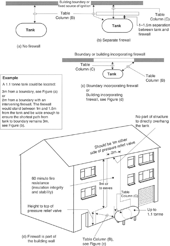
Figure 6.19.1 Separation or shielding of LPG tanks from the building, boundaries and fixed sources of ignition
p.892
![]() Note: Further guidance on LPG pipework can be found in the Gas Safety (Installation and Use) Regulations 1998 (GSIUR), the UKLPG Code of Practice 22 and the Institution of Gas Engineers and Managers standard IG/TD/4.
Note: Further guidance on LPG pipework can be found in the Gas Safety (Installation and Use) Regulations 1998 (GSIUR), the UKLPG Code of Practice 22 and the Institution of Gas Engineers and Managers standard IG/TD/4.

p.893

Figure 6.19.2 Location of LPG cylinders
6.20 Kitchens and utility rooms
6.20.1 Requirements

p.894

6.20.2 Meeting the requirements
6.20.2.1 Fire safety
6.20.2.1.1 Smoke alarms
![]() Note: Detectors respond differently to smouldering and fast-flaming fires and therefore should, if possible, take into account the type of fire that might be expected and the need to avoid false alarms. Optical detectors are generally more suitable for installation in circulation spaces adjacent to kitchens.
Note: Detectors respond differently to smouldering and fast-flaming fires and therefore should, if possible, take into account the type of fire that might be expected and the need to avoid false alarms. Optical detectors are generally more suitable for installation in circulation spaces adjacent to kitchens.
6.20.2.1.2 Escape routes

p.895
Cold water pipes that pass through a compartment wall or compartment floor (unless the pipe is in a protected shaft), or through a cavity barrier, should incorporate one of the following alternatives:

p.896

Figure 6.20.1 Pipes penetrating a structure
6.20.2.1.3 Refuse chutes and storage
In buildings containing flats, any wall that encloses a refuse storage chamber should be constructed as a compartment wall. Refuse storage chambers, refuse chutes and refuse hoppers should be sited and constructed in accordance with BS 5906.
6.20.2.2 Site preparation and resistance to contaminants and moisture
6.20.2.2.1 Floor coverings

![]() Note: Chipboard should be of a grade with improved moisture resistance (BS 7331 or BS EN 312). It should be laid, fixed and jointed in the manner recommended by the manufacturer. To demonstrate compliance, the identification marks face upwards. Any softwood boarding should be at least 20mm thick and from a durable species or treated with a suitable preservative.
Note: Chipboard should be of a grade with improved moisture resistance (BS 7331 or BS EN 312). It should be laid, fixed and jointed in the manner recommended by the manufacturer. To demonstrate compliance, the identification marks face upwards. Any softwood boarding should be at least 20mm thick and from a durable species or treated with a suitable preservative.
p.897
6.20.2.2.2 Roofs
To avoid excessive moisture transfer to roof voids the gaps and penetrations for pipes and electrical wiring should be filled and sealed. This is particularly important in areas of high humidity, e.g. kitchens. An effective draught seal should be provided to loft hatches to reduce inflow of warm air and moisture.

The requirement will be met by the ventilation of cold deck roofs, i.e. those roofs where the moisture from the building can permeate the insulation. For the purposes of health and safety it may not always be necessary to provide ventilation to small roofs such as those over porches and bay windows.
Any part of a roof which has a pitch of 70° or more should be insulated as though it were a wall.
6.20.2.3 Resistance to the passage of sound
6.20.2.3.1 Refuse chutes

6.20.2.3.2 Tests for sound between rooms

p.898
6.20.2.4 Ventilation

![]() Extract ventilation may be by natural means such as by Passive Stack Ventilation (PSV) or by mechanical means such as an extract fan or central system, but note that it is now a mandatory requirement that, if you carry out any ‘building work’ and there is an existing extract fan, PSV or cooker hood extracting to outside in the kitchen, you should either retain or replace it.
Extract ventilation may be by natural means such as by Passive Stack Ventilation (PSV) or by mechanical means such as an extract fan or central system, but note that it is now a mandatory requirement that, if you carry out any ‘building work’ and there is an existing extract fan, PSV or cooker hood extracting to outside in the kitchen, you should either retain or replace it.

6.20.2.4.1 The purpose of ventilation
The pollutant(s) of most importance will vary between building types and building and the common pollutants in a dwelling are moisture and combustion products from unflued appliances (e.g. gas, oil or solid fuel cookers) and chemical emissions from construction and consumer products.
![]() The ventilation system capacity, if used appropriately, is usually sufficient to remove odours arising from normal occupant activities within a dwelling.
The ventilation system capacity, if used appropriately, is usually sufficient to remove odours arising from normal occupant activities within a dwelling.
6.20.2.4.2 Control of ventilation

p.899

![]() Note: Manual boost controls should also be provided in kitchens to guard against the possibility of a single centrally located switch being left in an incorrect mode of operation.
Note: Manual boost controls should also be provided in kitchens to guard against the possibility of a single centrally located switch being left in an incorrect mode of operation.
6.20.2.4.3 Ventilation rates

Table 6.20.1 Extract ventilation rates - kitchens


p.900

![]() If any of the work being carried out in the kitchen of an existing building is ‘building work’ (as defined in Regulation 3 of the Building Regulations) then you will need to comply with the appropriate requirements of this regulation.
If any of the work being carried out in the kitchen of an existing building is ‘building work’ (as defined in Regulation 3 of the Building Regulations) then you will need to comply with the appropriate requirements of this regulation.

p.901
6.20.2.4.4 Refurbishing a kitchen or bathroom in an existing dwelling

The definition of ‘building work’ in Regulation 3 of the Building Regulations includes a range of building activities in existing buildings, and includes all work on controlled services. For more information, see the Building Regulations at www.planningportal.gov.uk.

![]() Appendix C to Approved Document F gives example calculations for ventilation sizing for dwellings
Appendix C to Approved Document F gives example calculations for ventilation sizing for dwellings
6.11.2.5 Sanitation, hot water safety and water efficiency
![]() Note: Kitchen means a room or part of a room which contains a sink and food preparation facilities.
Note: Kitchen means a room or part of a room which contains a sink and food preparation facilities.
6.20.2.5.1 Sanitary conveniences and washing facilities
![]() Note: In dwellings, a room containing both a sanitary convenience and a basin for hand washing does not need a separation lobby between this room and a kitchen or food preparation area (Figure 6.20.1). The layout for a room containing a sanitary convenience only should be such that the room or space containing its associated hand-washing facilities is accessed before entry to a food preparation area, and is separated from that area by a door (Figure 6.20.2).
Note: In dwellings, a room containing both a sanitary convenience and a basin for hand washing does not need a separation lobby between this room and a kitchen or food preparation area (Figure 6.20.1). The layout for a room containing a sanitary convenience only should be such that the room or space containing its associated hand-washing facilities is accessed before entry to a food preparation area, and is separated from that area by a door (Figure 6.20.2).
p.902

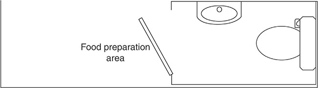
Figure 6.20.2 Separation between hand basin/WC and food preparation area – single room

Figure 6.20.3 Separation between hand basin/WC and food preparation area – two rooms
p.903
6.20.2.5.2 Chemical or composting toilets

6.20.2.5.4 Scale of provision in dwellings

6.20.2.5.5 Discharges to drains

Table 6.20.2 Water efficiency calculator – kitchens

p.904

![]() Note: Approved Document H1 provides guidance on drainage, the provision for traps, discharge pipes and stacks and foul drains.
Note: Approved Document H1 provides guidance on drainage, the provision for traps, discharge pipes and stacks and foul drains.
6.20.2.5.6 Cold water supplies
The cold water supply shall:

6.20.2.5.7 Cold water storage systems

6.20.2.5.8 Storage of food
In accordance with Building Act 1984 Sections 28 and 70, all houses or buildings that have been converted into dwellings must provide sufficient and suitable accommodation for storing food or ‘sufficient and suitable space for the provision of such accommodation by the occupier’.
p.905
6.20.2.5.9 Alternative sources of water

6.20.2.6 Drainage and waste disposal

6.20.2.7 Access to and use of buildings
![]() Requirements M4(2) and M4(3) of Approved Document M Volume 1 (referred to as M1) are optional requirements. There are no compulsory requirements relating to access in kitchens.
Requirements M4(2) and M4(3) of Approved Document M Volume 1 (referred to as M1) are optional requirements. There are no compulsory requirements relating to access in kitchens.
6.20.2.7.1 Living, kitchen and eating areas

p.906

![]() Note: Drawings should be provided which show how the kitchen could be easily adapted to meet the requirements for accessible dwellings at a future date without compromising the space in any other part of the dwelling and without the need to move structural walls, stacks or concealed drainage.
Note: Drawings should be provided which show how the kitchen could be easily adapted to meet the requirements for accessible dwellings at a future date without compromising the space in any other part of the dwelling and without the need to move structural walls, stacks or concealed drainage.
p.907


Figure 6.20.4 Example of wheelchair-accessible kitchen layout
6.20.2.7.2 Through-floor lifting device provision

6.20.2.8 Electrical safety – dwellings
p.908
6.21.1 Requirements

p.909

p.910

6.21.2 Meeting the requirement
6.21.2.1 Fire safety
Where the conversion of an existing roof space (e.g. a loft conversion to a two-storey house) means that a new storey is going to be added, then the stairway will need to be protected with fire-resisting doors and partitions.
p.911

![]() Note: If it is considered undesirable to replace existing doors (e.g. if they are of historical or architectural merit), it may be possible to retain the doors or upgrade them to an acceptable standard
Note: If it is considered undesirable to replace existing doors (e.g. if they are of historical or architectural merit), it may be possible to retain the doors or upgrade them to an acceptable standard
6.21.2.2 Resistance to contaminants
Care should be taken when working on sites affected by contaminants where control measures are already in place not to compromise these measures.

p.912
6.21.2.3 Cavity insulation

![]() Fumes given off by insulating materials such as by urea formaldehyde (UF) foams should not be allowed to penetrate occupied parts of buildings where they could become a health risk to persons in the building touching an irritant concentration.
Fumes given off by insulating materials such as by urea formaldehyde (UF) foams should not be allowed to penetrate occupied parts of buildings where they could become a health risk to persons in the building touching an irritant concentration.
6.21.2.4 Resistance to the passage of sound

![]() New walls and floors within a dwelling should provide a minimum sound insulation value of 40 RW dB.
New walls and floors within a dwelling should provide a minimum sound insulation value of 40 RW dB.

Special attention also needs to be given to situations where flanking walls or floors are continuous across separating walls or floors as a result of the conversion work. In such instances, additional treatments may be required to control flanking transmission along these continuous elements. Specialist advice may be needed.
Significant differences may frequently occur between the construction and layout of each converted unit in a development. In these cases, the Building Control Body (BCB) will provide guidance concerning:
• the application of pre-completion testing to material change of use
• floor or wall penetrations, such as ducts or pipes, passing through separating elements in conversions (which can reduce the level of sound insulation)
• piped services (excluding gas pipes) and ducts which pass through separating floors in conversions (which should be surrounded with sound-absorbent material for their full height and enclosed in a duct above and below the floor).
p.913
6.21.2.5 Ventilation
If the additional room is connected to an existing habitable room has:
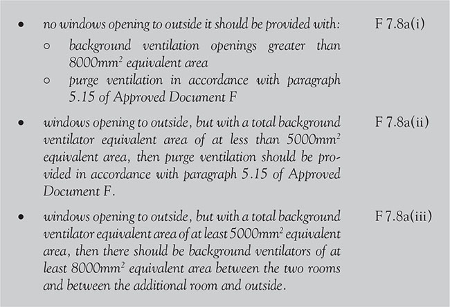
If the extension is the addition of a habitable room to an existing building, then:

p.914
![]() Care should be taken when installing ducting for fans through an unheated void or loft space.
Care should be taken when installing ducting for fans through an unheated void or loft space.
![]() Note: Avoid peaks and troughs in ducting and consider the use of condensation traps to prevent the backflow of moisture where necessary.
Note: Avoid peaks and troughs in ducting and consider the use of condensation traps to prevent the backflow of moisture where necessary.
6.21.2.6 Sanitation, hot water safety and water efficiency
The regulations relating to sanitation apply equally to loft conversions. If you plan to install a bathroom in a loft conversion, see Chapter 6.15 of this book.

6.21.2.7 Protection from falling, collision and impact

You may use alternating tread stairs – in one or more straight flights – only in a loft conversion, and only when there is not enough space for a stair that satisfies paragraphs 1.2–1.24 of Approved Document K, and the stair is for access to only one habitable room and, if desired, a bathroom and/or a WC.
p.915

Figure 6.21.1 Reduced headroom on stairs in loft conversions

p.916

Figure 6.21.2 Alternating tread stairs in loft conversions
![]() Note: This requirement applies to stairs that form part of the building.
Note: This requirement applies to stairs that form part of the building.
6.21.2.8 Conservation of fuel and power
6.21.2.8.1 Retained thermal elements
Thermal elements may be retained when an existing element becomes part of the thermal envelope where previously it was not, e.g. as part of a loft conversion or where an existing thermal element is part of a building which is subject to a material change of use.
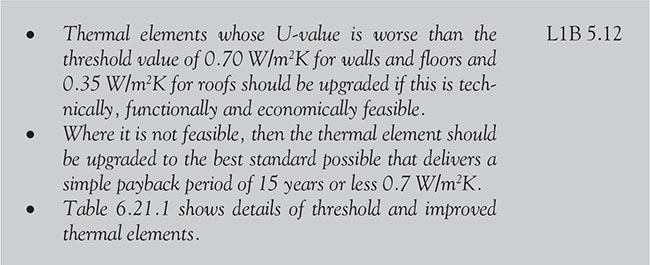
![]() When upgrading retained thermal element particular attention should be paid to Approved Documents F and J.
When upgrading retained thermal element particular attention should be paid to Approved Documents F and J.
p.917
Table 6.21.1 Upgrading retained thermal elements

6.21.2.8.2 Work covered by Approved Document L1B
Approved Document L1B provides guidance for those carrying out work on existing dwellings on what is considered to be compliance with the Regulations. Under Regulation 17D of the Building Regulations, the construction of a loft extension will trigger the requirement for consequential improvements.
![]() Note: Buildings exclusively containing rooms for residential purposes such as nursing homes, student accommodation and similar are not dwellings, and are covered in Chapter 7.
Note: Buildings exclusively containing rooms for residential purposes such as nursing homes, student accommodation and similar are not dwellings, and are covered in Chapter 7.

6.21.2.8.3 Material change of use
Changes which constitute a material change of use may require thermal elements to be upgraded.

p.918

![]() Note: A material alteration may result in a change in buildings energy status.
Note: A material alteration may result in a change in buildings energy status.
6.21.2.8.4 Change of energy status
Changes which result in a building now becoming subject to the regulations where previously it did not are called a change of energy status.

In this regulation ‘building’ means the building as a whole or parts of the building that have been designed or altered to be used separately. For example, this could occur if a previously unheated building, or parts of the building that have been designed or altered to be used separately, were to be heated in future, or where a previously exempt building were no longer within the exempted categories.

p.919
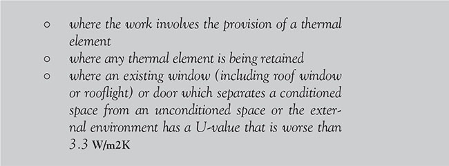
To provide more design flexibility, SAP 2012 can be used to demonstrate that the total C02 emissions from all the dwellings in the building as it will become are no greater than if each dwelling had been improved following the guidance set out in paragraph
Table 6.21.2 Standards for new thermal elements
![]() If you are adding a loft conversion, make sure any conservatory does not restrict ladder access to windows serving rooms in the loft conversions, particularly if any of the windows are intended to help escape or rescue if there is a fire.
If you are adding a loft conversion, make sure any conservatory does not restrict ladder access to windows serving rooms in the loft conversions, particularly if any of the windows are intended to help escape or rescue if there is a fire.
6.21.2.9 Security
The new Approved Document Q (Security) applies to any dwelling (or part of a building from which access can be gained to a flat within that building) and requires secure doors and windows to be fitted in dwellings.

p.920
6.22 Extensions and additions to buildings
This section covers specific guidance relating to Extensions and Additions. Any requirements covered by other sections of this chapter e.g. Loft conversions (Section 6.22) and Conservatories (6.24) should be used in conjunction with this section.
6.22.1 Requirements

p.921

p.922

The construction of an extension may trigger the requirement for “consequential improvements” (Regulation 17D of the Building Regulations). For example, if a building has a total useful floor area greater than 1000m3 and the proposed building work includes an extension, or the initial provision of any fixed building service, or an increase to the installed capacity of any fixed building services, consequential improvements should be made to improve the energy efficiency of the whole building and:
• thermal units with high U-values should be upgraded
• existing windows (but not display windows), roof windows, rooflights and doors (excluding high-usage entrance doors) within the area served by the fixed building service with an increased capacity should be replaced
• heating systems, cooling systems and air-handling systems that are more than 15 years old should either be replaced or be equipped with improved controls
p.923
• any general lighting system serving an area greater than 100m2 which has an average lamp efficacy of less than 40 lamp-lumens per circuit-watt, should be upgraded with new luminaires or improved controls
• energy metering should be installed if less than 10 percent of the building’s energy demand is provided by a Low- or Zero Carbon (LZC) energy system; and
• the building should be upgraded with an additional LZC energy system, provided that the system would achieve a simple payback within seven years or less.
![]() Note:
Note:
1. The size of single-storey rear extensions which can be built under permitted development has been temporarily increased (until May 2019) and an associated neighbour consultation scheme has been introduced. Householders may build larger single-storey rear extensions under permitted development (up to 8m for detached houses, and 6m for all other houses). More information on this is contained in Chapters 4 and 5.
2. Approved Document P (Electrical Safety) applies to extensions that share their electricity with a dwelling.
3. Requirement R (Physical infrastructure for high-speed electronic communications networks) does not apply to sheds, domestic greenhouses, garages, conservatories and other small detached buildings with no sleeping accommodation.
6.22.2 Meeting the requirement
6.22.2.1 Fire safety
The chances of fire spreading across an open space between buildings should be limited as much as possible. At a minimum, the building should not have a lesser level of compliance, after the work has been completed than it did before work commenced.

p.924

![]() Approved Document B includes a requirement for the responsible person (i.e. the person carrying out work to a building) to make available to the owner (other than houses occupied as single private dwellings) ‘fire safety information’ concerning the design and construction of the building or extension, plus details of the services, fittings and equipment that have been provided in order that they may complete a fire risk analysis. The sort of information required must include basic advice on the proper use and maintenance of systems provided in the building such as:
Approved Document B includes a requirement for the responsible person (i.e. the person carrying out work to a building) to make available to the owner (other than houses occupied as single private dwellings) ‘fire safety information’ concerning the design and construction of the building or extension, plus details of the services, fittings and equipment that have been provided in order that they may complete a fire risk analysis. The sort of information required must include basic advice on the proper use and maintenance of systems provided in the building such as:
• emergency egress windows
• fire doors
• smoke alarms
• sprinklers, etc.
p.925

Figure 6.22.1 Means of escape from an extension
6.22.2.2 Resistance to contaminants
Care should be taken when working on sites affected by contaminants where control measures are already in place not to compromise these measures (e.g. breaching a cover system when extension foundations are constructed).

p.926
6.22.2.3 Cavity insulation

6.22.2.4 Resistance to the passage of sound

![]() Note: New walls and floors within a dwelling (including extensions) should provide a minimum sound insulation value of 40 RW dB.
Note: New walls and floors within a dwelling (including extensions) should provide a minimum sound insulation value of 40 RW dB.
6.22.2.5 Means of ventilation
If the additional room is connected to an existing habitable room has:

If the extension is the addition of a habitable room to an existing building, then:
p.927

6.22.2.6 Sanitation, hot water safety and water efficiency
The regulations relating to sanitation [G1, G3(2) and G3(3)] apply equally to extensions where they share facilities with another building which is covered by the Regulations.

p.928
![]() Note: The Regulations do not require hot or cold water systems to be provided to exempt buildings. If systems are provided, then they must meet the minimum hygiene and safety requirements laid out in the Approved Documents.
Note: The Regulations do not require hot or cold water systems to be provided to exempt buildings. If systems are provided, then they must meet the minimum hygiene and safety requirements laid out in the Approved Documents.
6.22.2.7 Conservation of fuel and power
6.22.2.7.1 Changes in the legal requirements
Some extensions are exempt from the energy efficiency requirements of the Building Regulations. This exemption only applies where the existing doors are retained (or replaced) and where the extension:
• is at ground level
• has a floor area is less than 30m2
• has either retained the existing walls, doors and windows of the dwelling or, if removed, have been replaced by walls, windows and doors which meet the energy efficiency requirements of Approved Document L; and
• has not been affected by the heating system of the dwelling being extended into it.
If a new extension does not meet all the requirements above then it is not exempt and must comply with the relevant energy efficiency requirements of Approved Document L, and reasonable provision should be provided to ensure that:

![]() Doors which have less than 50 percent of their internal face glazed should not exceed 1.8 W/m2 K
Doors which have less than 50 percent of their internal face glazed should not exceed 1.8 W/m2 K
If a building extension is not exempt from the energy efficiency requirements, then:

p.929

![]() If you remove but do not replace any of the thermal separation between the building and an existing exempt extension, or you extend the building’s heating system into the extension then the extension will no longer be exempt!
If you remove but do not replace any of the thermal separation between the building and an existing exempt extension, or you extend the building’s heating system into the extension then the extension will no longer be exempt!
Table 6.22.1 Standards for controlled fittings in dwellings

Table 6.22.2 Standards for new thermal elements in dwellings

In most circumstances the most reasonable provision would be to limit the total area of windows, roof windows and doors in extensions so that it does not exceed the sum of:
• 25 percent of the floor area of the extension; plus
• the total area of any windows or doors which, as a result of the extension works, no longer exist or are no longer exposed.
p.930
![]() Where the proposed extension has a total useful floor area that is both greater than 1000m2; and greater than 25 percent of the total useful floor area of the existing building then the work should be regarded as a new building.
Where the proposed extension has a total useful floor area that is both greater than 1000m2; and greater than 25 percent of the total useful floor area of the existing building then the work should be regarded as a new building.
![]() One way of complying would be to show that the area-weighted U-value of all the elements in the extension is no greater than that of an extension of the same size and shape.
One way of complying would be to show that the area-weighted U-value of all the elements in the extension is no greater than that of an extension of the same size and shape.

Table 6.22.3 Upgrading retained thermal elements in dwellings

6.22.2.7.2 Historic and traditional buildings
![]() When undertaking work on any historic or traditional building, the aim should always be to improve energy efficiency as far as is reasonably practicable without prejudicing the character of the host building or increasing the risk of long-term deterioration of the building fabric or fittings.
When undertaking work on any historic or traditional building, the aim should always be to improve energy efficiency as far as is reasonably practicable without prejudicing the character of the host building or increasing the risk of long-term deterioration of the building fabric or fittings.
![]() Building Inspectors normally require the use of ‘sympathetic treatment’ when restoring the historic character of a building that has been subject to previous inappropriate alteration (e.g. replacement doors).
Building Inspectors normally require the use of ‘sympathetic treatment’ when restoring the historic character of a building that has been subject to previous inappropriate alteration (e.g. replacement doors).
p.931
Particular issues that could warrant sympathetic treatment include:

6.22.2.8 Access to and use of buildings – optional requirement
Providing access able doorways to conservatories in dwellings is an optional requirement should you wish to follow the following sections of Approved Document M4 (2)


p.932
6.22.2.9 Security
The new Approved Document Q (Security) applies to any dwelling or part of a building where access can be gained to a flat within that building and the requirement is for secure doors and windows to be fitted in that dwelling.

p.933
6.23.1 Requirements

p.934

![]() Conservatories, porches and domestic greenhouses that share their electricity with a dwelling are not exempt from Part P (Electrical Safety) and must comply with its requirements.
Conservatories, porches and domestic greenhouses that share their electricity with a dwelling are not exempt from Part P (Electrical Safety) and must comply with its requirements.
![]() Note: Until May 2019 ,under permitted development in England, householders may build larger single-storey conservatories of up to 8m2 for detached houses and 6m2 for all other houses. More information is contained in Chapters 4 and 5.
Note: Until May 2019 ,under permitted development in England, householders may build larger single-storey conservatories of up to 8m2 for detached houses and 6m2 for all other houses. More information is contained in Chapters 4 and 5.
![]() Requirement R (Physical infrastructure for high-speed electronic communications networks) does not apply to conservatories and other small detached buildings which have no sleeping accommodation.
Requirement R (Physical infrastructure for high-speed electronic communications networks) does not apply to conservatories and other small detached buildings which have no sleeping accommodation.
6.23.2 Meeting the requirement
6.23.2.1 Fire safety
Some roof coverings (such as plastic roof lights) do not provide protection against the spread of fire and therefore are not permitted adjacent to a boundary.
6.23.2.2 Ventilation
The general ventilation rate for conservatories (and adjoining rooms) with a floor area greater than 30m2, can be achieved by the use of background ventilators (e.g. air bricks).
p.935
Table 6.23.1 Class 3 (National class) or Class D-s3, d2 (European class) plastic rooflights limitations on use and boundary distance

Table 6.23.2 Plastic rooflights: limitations on use and boundary distance

p.936
![]() Note: Further guidance on the size of purge ventilation, and the location and control of this ventilation in new dwellings is given in Section 6.2.
Note: Further guidance on the size of purge ventilation, and the location and control of this ventilation in new dwellings is given in Section 6.2.

Figure 6.23.1 Ventilation for a habitable room through a conservatory
6.23.2.3 Sanitation
The regulations relating to sanitation apply equally to conservatories where they share facilities with another building which is covered by the Regulations.

p.937
![]() Note: The Regulations do not require hot or cold water systems to be provided in exempt buildings, but if systems are provided they must meet the minimum hygiene and safety requirements in the Approved Documents.
Note: The Regulations do not require hot or cold water systems to be provided in exempt buildings, but if systems are provided they must meet the minimum hygiene and safety requirements in the Approved Documents.
6.23.2.4 Conservation of fuel and power
Conservatories in a new dwelling should follow the guidance of Approved Document L1B with regard to energy efficiency unless the dwelling’s heating system is extended into the conservatory or there is inadequate (or no) thermal separation between the dwelling and the conservatory – in which case Approve Document L1A applies.
6.23.2.4.1 New dwellings
Where conservatories are installed at the same time as the construction of a new dwelling:

![]() Under Regulation 17D of the Building Regulations, the construction of a conservatory may trigger the requirement for consequential improvements.
Under Regulation 17D of the Building Regulations, the construction of a conservatory may trigger the requirement for consequential improvements.
A conservatory extension in an existing dwelling is exempt from the regulations as long as the existing walls, windows and doors are retained (or replaced) and the heating system is not extended into the conservatory.

p.938

Where the conservatory is not exempt from the energy efficiency requirements:

![]() Note: The limitations set out in Approved Document L1B 4.2 on total permittable areas of windows, roof windows and doors do not apply in the case of conservatories.
Note: The limitations set out in Approved Document L1B 4.2 on total permittable areas of windows, roof windows and doors do not apply in the case of conservatories.
Table 6.23.3 Standards for controlled fittings

p.939
Table 6.23.4 Standards for new thermal elements

Table 6.23.5 Upgrading retained thermal elements

![]() Notes:
Notes:
1. It is not advised to construct conservatories where they will restrict ladder access to windows serving rooms in roof or loft conversions, particularly if any of the windows are intended to help escape or rescue if there is a fire.
2. Any new structural opening between the conservatory and the existing house will require Building Regulations approval, even if the conservatory itself is an exempt structure.
6.23.2.5 Access to and use of buildings – optional requirement
Providing access able doorways to conservatories in dwellings is an optional requirement should you wish to follow the following sections of Approved Document M4 (2).
p.940

6.23.2.6 Security
The new Approved Document Q (Security) requires secure doors and windows to be fitted in dwellings and/or part of a building from which access can be gained to a flat within the building.

p.941
