
CHAPTER 14
Network Components
This chapter presents the following:
• Transmission media
• Network devices
• Endpoint security
• Content distribution networks
The hacker didn’t succeed through sophistication. Rather he poked at obvious places, trying to enter through unlocked doors. Persistence, not wizardry, let him through.
In the previous chapter, we covered how to defend our networks. Let’s now talk about securing the components of those networks. We need to pay attention to everything from the cables, to the network devices, to the endpoints, because our adversaries will poke at all of it, looking for ways to get in. We (defenders) have to get it right all the time; they (attackers) only need to find that one chink in our armor to compromise our systems. In this chapter, we focus on physical devices. In the next chapter, we’ll drill into the software systems that run on them.
Transmission Media
We’ve already talked a fair bit about the protocols that allow us to move data from point A to point B, but we haven’t really covered what actually carries this information. A transmission medium is a physical thing through which data is moved. If we are speaking with each other, our vocal chords create vibrations in the air that we expel from our lungs, in which case the air is the transmission medium. Broadly speaking, we use three different types of transmission media:
• Electrical wires Encode information as changes in the voltage level of an electric current. Typically, we use cables, which are two or more wires encased within a sheath.
• Optical fibers Transmit data that is encoded in the wavelength (color), phase, or polarization of the light. The light is generated by either an LED or a laser diode. As with electrical wires, we usually bundle multiple fibers into cables for longer distances.
• Free space The medium we use for wireless communications, covered in Chapter 12. Any electromagnetic signal can travel through free space even outside our atmosphere. We tend to use mostly radio signals in free space, but every now and then you may encounter a system that uses light, such as infrared laser beams.
Types of Transmission
Physical data transmission can happen in different ways (analog or digital); can use different synchronization schemes (synchronous or asynchronous); can use either one sole channel over a transmission medium (baseband) or several different channels over a transmission medium (broadband); and can take place as electrical voltage, radio waves, or optical signals. These transmission types and their characteristics are described in the following sections.
Analog vs. Digital
A signal is just some way of moving information in a physical format from one point to another point. You can signal a message to another person through nodding your head, waving your hand, or giving a wink. Somehow you are transmitting data to that person through your signaling method. In the world of technology, we have specific carrier signals that are in place to move data from one system to another system. The carrier signal is like a horse, which takes a rider (data) from one place to another place. Data can be transmitted through analog or digital signaling formats. If you are moving data through an analog transmission technology (e.g., radio), then the data is represented by the characteristics of the waves that are carrying it. For example, a radio station uses a transmitter to put its data (music) onto a radio wave that travels all the way to your antenna. The information is stripped off by the receiver in your radio and presented to you in its original format—a song. The data is encoded onto the carrier signal and is represented by various amplitude and frequency values, as shown in Figure 14-1.
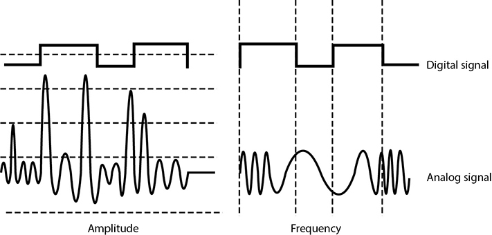
Figure 14-1 Analog signals are measured in amplitude and frequency, whereas digital signals represent binary digits as electrical pulses.
Data being represented in wave values (analog) is different from data being represented in discrete voltage values (digital). As an analogy, compare an analog clock and a digital clock. An analog clock has hands that continuously rotate on the face of the clock. To figure out what time it is, you have to interpret the position of the hands and map their positions to specific values. So you have to know that if the small hand is on the number 1 and the large hand is on the number 6, this actually means 1:30. The individual and specific location of the hands corresponds to a value. A digital clock does not take this much work. You just look at it and it gives you a time value in the format of hour:minutes. There is no mapping work involved with a digital clock because it provides you with data in clear-cut formats.
An analog clock can represent different values as the hands move forward—1:35 and 1 second, 1:35 and 2 seconds, 1:35 and 3 seconds. Each movement of the hands represents a specific value just like the individual data points on a wave in an analog transmission. A digital clock provides discrete values without having to map anything. The same is true with digital transmissions: the values are almost always binary, meaning they are either a 1 or a 0—no need for mapping to find the actual value.
Computers have always worked in a binary manner (1 or 0). When our telecommunication infrastructure was purely analog, each system that needed to communicate over a telecommunication line had to have a modem (modulator/demodulator), which would modulate the digital data into an analog signal. The sending system’s modem would modulate the data on to the signal, and the receiving system’s modem would demodulate the data off the signal.
Digital signals are more reliable than analog signals over a long distance and provide a clear-cut and efficient signaling method because the voltage is either on (1) or not on (0), compared to interpreting the waves of an analog signal. Extracting digital signals from a noisy carrier is relatively easy. It is difficult to extract analog signals from background noise because the amplitudes and frequencies of the waves slowly lose form. This is because an analog signal could have an infinite number of values or states, whereas a digital signal exists in discrete states. A digital signal is a square wave, which does not have all of the possible values of the different amplitudes and frequencies of an analog signal. Digital systems can implement compression mechanisms to increase data throughput, provide signal integrity through repeaters that “clean up” the transmissions, and multiplex different types of data (voice, data, video) onto the same transmission channel.
Asynchronous vs. Synchronous
Analog and digital transmission technologies deal with the characteristics of the physical carrier on which data is moved from one system to another. Asynchronous and synchronous transmission types are similar to the cadence rules we use for conversation synchronization. Asynchronous and synchronous network technologies provide synchronization rules to govern how systems communicate to each other. If you have ever spoken over a satellite phone, you have probably experienced problems with communication synchronization. Commonly, when two people are new to using satellite phones, they do not allow for the necessary delay that satellite communication requires, so they “speak over” one another. Once they figure out the delay in the connection, they resynchronize their timing so that only one person’s data (voice) is transmitting at one time, enabling each person to properly understand the full conversation. Proper pauses frame your words in a way to make them understandable.
Synchronization through communication also happens when we write messages to each other. Properly placed commas, periods, and semicolons provide breaks in text so that the person reading the message can better understand the information. If you see “stickwithmekidandyouwillweardiamonds” without the proper punctuation, it is more difficult for you to understand. This is why we have grammar rules. If someone writes a letter to you that starts from the bottom and right side of a piece of paper, and that person does not inform you of this unconventional format, you will not be able to read the message properly, at least initially.
Technological communication protocols also have their own grammar and synchronization rules when it comes to the transmission of data. If two systems are communicating over a network protocol that employs asynchronous timing, they use start and stop bits. The sending system sends a “start” bit, then sends its character, and then sends a “stop” bit. This happens for the whole message. The receiving system knows when a character is starting and stopping; thus, it knows how to interpret each character of the message. This is akin to our previous example of using punctuation marks in written communications to convey pauses. If the systems are communicating over a network protocol that uses synchronous timing, then they don’t add start and stop bits. The whole message is sent without artificial breaks, but with a common timing signal that allows the receiver to know how to interpret the information without these bits. This is similar to our satellite phone example in which we use a timing signal (i.e., we count off seconds in our head) to ensure we don’t talk over the other person’s speech.
If two systems are going to communicate using a synchronous transmission technology, they do not use start and stop bits, but the synchronization of the transfer of data takes place through a timing sequence, which is initiated by a clock pulse.
It is the data link protocol that has the synchronization rules embedded into it. So when a message goes down a system’s network stack, if a data link protocol, such as High-level Data Link Control (HDLC), is being used, then a clocking sequence is in place. (The receiving system must also be using this protocol so that it can interpret the data.) If the message is going down a network stack and a protocol such as Asynchronous Transfer Mode (ATM) is at the data link layer, then the message is framed with start and stop indicators.
Data link protocols that employ synchronous timing mechanisms are commonly used in environments that have systems that transfer large amounts of data in a predictable manner (i.e., data center environment). Environments that contain systems that send data in a nonpredictable manner (i.e., Internet connections) commonly have systems with protocols that use asynchronous timing mechanisms.
So, synchronous communication protocols transfer data as a stream of bits instead of framing it in start and stop bits. The synchronization can happen between two systems using a clocking mechanism, or a signal can be encoded into the data stream to let the receiver synchronize with the sender of the message. This synchronization needs to take place before the first message is sent. The sending system can transmit a digital clock pulse to the receiving system, which translates into, “We will start here and work in this type of synchronization scheme.” Many modern bulk communication systems, such as high-bandwidth satellite links, use Global Positioning System (GPS) clock signals to synchronize their communications without the need to include a separate channel for timing.
Table 14-1 provides an overview of the differences between asynchronous and synchronous transmissions.
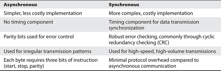
Table 14-1 Main Differences Between Asynchronous and Synchronous Transmissions
Broadband vs. Baseband
As you read, analog transmission means that data is being moved as waves, and digital transmission means that data is being moved as discrete electric pulses. Synchronous transmission means that two devices control their conversations with a clocking mechanism, and asynchronous means that systems use start and stop bits for communication synchronization. Now let’s look at how many individual communication sessions can take place at one time.
A baseband technology uses the entire communication channel for its transmission, whereas a broadband technology divides the communication channel into individual and independent subchannels so that different types of data can be transmitted simultaneously. Baseband permits only one signal to be transmitted at a time, whereas broadband carries several signals over different subchannels. For example, a coaxial cable TV (CATV) system is a broadband technology that delivers multiple television channels over the same cable. This system can also provide home users with Internet access, but this data is transmitted at a different frequency range than the TV channels.
As an analogy, baseband technology only provides a one-lane highway for data to get from one point to another point. A broadband technology provides a data highway made up of many different lanes, so that not only can more data be moved from one point to another point, but different types of data can travel over the individual lanes.
Any transmission technology that “chops up” one communication channel into multiple channels is considered broadband. The communication channel is usually a specific range of frequencies, and the broadband technology provides delineation between these frequencies and provides techniques on how to modulate the data onto the individual subchannels. To continue with our analogy, we could have one large highway that could fit eight individual lanes—but unless we have something that defines these lanes and have rules for how these lanes are used, this is a baseband connection. If we take the same highway and lay down painted white lines, post traffic signs, add on and off ramps, and establish rules that drivers have to follow, now we are talking about broadband.
A digital subscriber line (DSL) uses one single phone line and constructs a set of high-frequency channels for Internet data transmissions. A cable modem uses the available frequency spectrum that is provided by a cable TV carrier to move Internet traffic to and from a household. Mobile broadband devices implement individual channels over a cellular connection, and Wi-Fi broadband technology moves data to and from an access point over a specified frequency set. The point is that there are different ways of cutting up one channel into subchannels for higher data transfer and that they provide the capability to move different types of traffic at the same time.
Cabling
The different types of transmission techniques we just covered eventually end up being used to send signals over either a cable or free space. We already covered wireless communications in Chapter 12, so let’s talk about cabling now.
Electrical signals travel as currents through cables and can be negatively affected by many factors within the environment, such as motors, fluorescent lighting, magnetic forces, and other electrical devices. These items can corrupt the data as it travels through the cable, which is why cable standards are used to indicate cable type, shielding, transmission rates, and maximum distance a particular type of cable can be used.
Coaxial Cable
Coaxial cable has a copper core that is surrounded by a shielding layer and grounding wire, as shown in Figure 14-2. This is all encased within a protective outer jacket. Compared to twisted-pair cable, coaxial cable is more resistant to electromagnetic interference (EMI), provides a higher bandwidth, and supports the use of longer cable lengths. So, why is twisted-pair cable more popular? Twisted-pair cable is cheaper and easier to work with, and the move to switched environments that provide hierarchical wiring schemes has overcome the cable-length issue of twisted-pair cable.
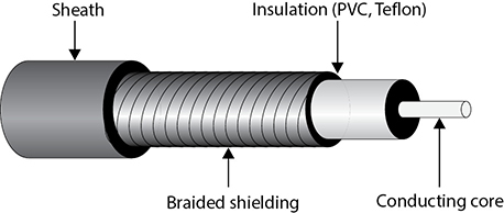
Figure 14-2 Coaxial cable
Coaxial cabling is used as a transmission line for radio frequency signals. If you have cable TV, you have coaxial cabling entering your house and the back of your TV. The various TV channels are carried over different radio frequencies. Modems allow us to use some of the “empty” TV frequencies for Internet connectivity.
Twisted-Pair Cable
Twisted-pair cabling has insulated copper wires surrounded by an outer protective jacket. If the cable has an outer foil shielding, it is referred to as shielded twisted pair (STP), which adds protection from radio frequency interference (RFI) and EMI. Twisted-pair cabling, which does not have this extra outer shielding, is called unshielded twisted pair (UTP).
The twisted-pair cable contains copper wires that twist around each other, as shown in Figure 14-3. This twisting of the wires protects the integrity and strength of the signals they carry. Each wire forms a balanced circuit, because the voltage in each pair uses the same amplitude, just with opposite phases. The tighter the twisting of the wires, the more resistant the cable is to interference and attenuation. UTP has several categories of cabling, each of which has its own unique characteristics.
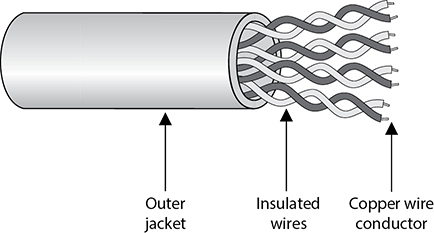
Figure 14-3 Twisted-pair cabling uses copper wires.
The twisting of the wires, the type of insulation used, the quality of the conductive material, and the shielding of the wire determine the rate at which data can be transmitted. The UTP ratings indicate which of these components were used when the cables were manufactured. Some types are more suitable and effective for specific uses and environments. Table 14-2 lists the cable ratings.
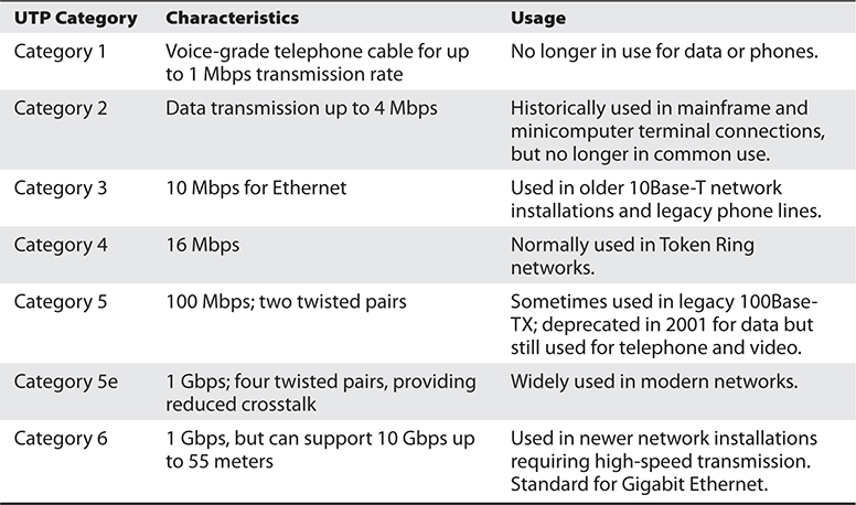
Table 14-2 UTP Cable Ratings
Copper cable has been around for many years. It is inexpensive and easy to use. A majority of the telephone systems today use copper cabling with the rating of voice grade. Twisted-pair wiring is the preferred network cabling, but it also has its drawbacks. Copper actually resists the flow of electrons, which causes a signal to degrade after it has traveled a certain distance. This is why cable lengths are recommended for copper cables; if these recommendations are not followed, a network could experience signal loss and data corruption. Copper also radiates energy, which means information can be monitored and captured by intruders. UTP is the least secure networking cable compared to coaxial and fiber. If an organization requires higher speed, higher security, and cables to have longer runs than what is allowed in copper cabling, fiber-optic cable may be a better choice.
Fiber-Optic Cable
Twisted-pair cable and coaxial cable use copper wires as their data transmission media, but fiber-optic cable uses a type of glass that carries light waves, onto which we modulate the data being transmitted. The glass core is surrounded by a protective cladding, which in turn is encased within an outer jacket.
Because it uses glass, fiber-optic cabling has higher transmission speeds that allow signals to travel over longer distances. Fiber-optic cabling is not as affected by attenuation and EMI when compared to cabling that uses copper. It does not radiate signals, as does UTP cabling, and is difficult to eavesdrop on; therefore, fiber-optic cabling is much more secure than UTP, STP, or coaxial.
Using fiber-optic cable sounds like the way to go, so you might wonder why you would even bother with UTP, STP, or coaxial. Unfortunately, fiber-optic cable is expensive and difficult to work with. It is usually used in backbone networks and environments that require high data transfer rates. Most networks use UTP and connect to a backbone that uses fiber.
 NOTE
NOTE
The price of fiber and the cost of installation have been steadily decreasing, while the demand for more bandwidth only increases. More organizations and service providers are installing fiber directly to the end user.
Cabling Problems
Cables are extremely important within networks, and when they experience problems, the whole network could experience problems. This section addresses some of the more common cabling issues many networks experience.
Noise
The term line noise refers to random fluctuations in electrical-magnetic impulses that are carried along a physical medium. Noise on a line is usually caused by surrounding devices or by characteristics of the wiring’s environment. Noise can be caused by motors, computers, copy machines, fluorescent lighting, and microwave ovens, to name a few. This background noise can combine with the data being transmitted over the cable and distort the signal, as shown in Figure 14-4. The more noise there is interacting with the cable, the more likely the receiving end will not receive the data in the form originally transmitted.

Figure 14-4 Background noise can merge with an electronic signal and alter the signal’s integrity.
Attenuation
Attenuation is the loss of signal strength as it travels. This is akin to rolling a ball down the floor; as it travels, air causes resistance that slows it down and eventually stops it. In the case of electricity, the metal in the wire also offers resistance to the flow of electricity. Though some materials such as copper and gold offer very little resistance, it is still there. The longer a wire, the more attenuation occurs, which causes the signal carrying the data to deteriorate. This is why standards include suggested cable-run lengths.
The effects of attenuation increase with higher frequencies; thus, 100Base-TX at 80 MHz has a higher attenuation rate than 10Base-T at 10 MHz. This means that cables used to transmit data at higher frequencies should have shorter cable runs to ensure attenuation does not become an issue.
If a networking cable is too long, attenuation will become a problem. Basically, the data is in the form of electrons, and these electrons have to “swim” through a copper wire. However, this is more like swimming upstream, because there is a lot of resistance on the electrons working in this media. After a certain distance, the electrons start to slow down and their encoding format loses form. If the form gets too degraded, the receiving system cannot interpret the electrons any longer. If a network administrator needs to run a cable longer than its recommended segment length, she needs to insert a repeater or some type of device that amplifies the signal and ensures that it gets to its destination in the right encoding format.
Attenuation can also be caused by cable breaks and malfunctions. This is why cables should be tested. If a cable is suspected of attenuation problems, cable testers can inject signals into the cable and read the results at the end of the cable.
 EXAM TIP
Most implementations of Ethernet over UTP have a maximum cable length of 100 meters, partly to deal with attenuation.
Crosstalk
Crosstalk is a phenomenon that occurs when electrical signals of one wire spill over to the signals of another wire. When electricity flows through a wire, it generates a magnetic field around it. If another wire is close enough, the second wire acts as an antenna that turns this magnetic field into an electric current. When the different electrical signals mix, their integrity degrades and data corruption can occur. UTP mitigates crosstalk by twisting the wires around each other. Because crosstalk is greatest wherever wires are parallel to each other, this twisting makes it harder for this condition to exist. Still, UTP is much more vulnerable to crosstalk than STP or coaxial because it does not have extra layers of shielding to help protect against it.
Fire Rating of Cables
Just as buildings must meet certain fire codes, so must wiring schemes. A lot of organizations string their network wires in drop ceilings—the space between the ceiling and the next floor—or under raised floors. This hides the cables and prevents people from tripping over them. However, when wires are strung in places like this, they are more likely to catch on fire without anyone knowing about it. Some cables produce hazardous gases when on fire that would spread throughout the building quickly. Network cabling that is placed in these types of areas, called plenum space, must meet a specific fire rating to ensure the cable will not produce and release harmful chemicals in case of a fire. A ventilation system’s components are usually located in this plenum space, so if toxic chemicals were to get into that area, they could easily spread throughout the building in minutes.
Nonplenum cables usually have a polyvinyl chloride (PVC) jacket covering, whereas plenum-rated cables have jacket covers made of fluoropolymers. When setting up a network or extending an existing network, it is important that you know which wire types are required in which situation.
Cables should be installed in unexposed areas so they are not easily tripped over, damaged, or eavesdropped upon. The cables should be strung behind walls and in the protected spaces, such as in dropped ceilings. In environments that require extensive security, wires can be encapsulated within pressurized conduits so if someone attempts to access a wire, the pressure of the conduit changes, causing an alarm to sound and a message to be sent to the security staff. A better approach to high-security requirements is probably to use fiber-optic cable, which is much more difficult to covertly tap.
NOTE
While a lot of the world’s infrastructure is wired and thus uses one of these types of cables, remember that a growing percentage of our infrastructure is not wired, but rather uses some form of wireless technology (Bluetooth, Wi-Fi, satellite, etc.), particularly to reach end devices.
Bandwidth and Throughput
Whatever type of transmission you use over any given cable, there is a limit to how much information you can encode within it. In computer networks, we use two different but related terms to measure this limit. Bandwidth is the amount of information that theoretically can be transmitted over a link within a second. In a perfect world, this is the data transfer capability of a connection and is commonly associated with the number of available frequencies and speed of a link. Data throughput is the actual amount of data that can be carried over a real link. Throughput is always less than or equal to a link’s bandwidth. In fact, it is most often the case that throughput is notably less than bandwidth. Why?
As mentioned, bandwidth is a theoretical limit determined by analyzing a medium (e.g., category 5 UTP cable) and a physical layer protocol (e.g., 100BaseT Ethernet) and then doing the math to calculate the maximum possible amount of data we could push through it. Now, of course, when you put that medium and protocol into a real environment, a multitude of issues come into play and make it hard to achieve that optimal data rate.
The throughput of our networks is affected by many factors. There could be EMI (or line noise) in the medium, as previously discussed. However, in a well-engineered facility and network, this should not be a big problem. Typically, you’ll be more concerned about packet delays and losses. Latency is the amount of time it takes a packet to get from its source to its destination. This could be measured as either time to first byte (TTFB) or round-trip time (RTT). Latency can be caused by multiple factors, including
• Transmission medium Even though electricity and light move at the speed of light, it still takes time to get from one place to another. If your links are very long, or if the cables have too many imperfections, the medium itself will cause latency.
• Network devices Routers and firewalls take some time to examine packets, even if they’re just deciding which outbound interface to use. If you have too many rules in your routing or security devices, this is invariably going to introduce delays.
To reduce latency, you should keep your physical links as short as possible. You should also look at how many hops your packets must take to get to their destinations. Virtual LANs (VLANs) can help keep devices that communicate frequently “closer” to each other. For international organizations, using a content distribution network (CDN), which we address later in this chapter, keeps most data close to where it is needed. Finally, the use of proxies can reduce latency by bringing frequently requested data closer to your users.
Another issue that negatively impacts your data throughputs (compared to a link’s rated bandwidth) is congestion. Since some links in your network are shared, if you have too many packets moving around, it will inevitably bog things down. You may have a 1-GBps (bandwidth) connection to your home, but if every house in your neighborhood has one too and you all share a 1-GBps link from the local switch to the first router, your throughput will be way lower than advertised unless you log on when everyone else is sleeping. The best way to prevent congestion is through careful design and implementation of your network. Keep your broadcast domains as small as possible, ensure that your shared links are able to support peak traffic rates, and consider prioritizing certain types of traffic so that if your staff decides to livestream news, that doesn’t slow down your ability to get real work done.
Network Devices
Several types of devices are used in LANs, MANs, and WANs to provide intercommunication among computers and networks. We need to have physical devices throughout the network to actually use all the protocols and services we have covered up to this point. The different network devices vary according to their functionality, capabilities, intelligence, and network placement. We will look at the following devices:
• Repeaters
• Bridges
• Switches
• Routers
• Gateways
• Proxy servers
• PBXs
• Network access control devices
The typical network has a bunch of these devices, and their purposes and operation can get confusing really quickly. Therefore, we will also look at network diagram techniques that can help us create different (simpler) views into complex environments. We’ll also consider operational issues like power requirements, warranties, and support agreements.
Repeaters
A repeater provides the simplest type of connectivity because it only repeats electrical signals between cable segments, which enables it to extend a network. Repeaters work at the physical layer and are add-on devices for extending a network connection over a greater distance. The device amplifies signals because signals attenuate the farther they have to travel.
Repeaters can also work as line conditioners by actually cleaning up the signals. This works much better when amplifying digital signals than when amplifying analog signals because digital signals are discrete units, which makes extraction of background noise from them much easier for the amplifier. If the device is amplifying analog signals, any accompanying noise often is amplified as well, which may further distort the signal.
A hub is a multiport repeater. A hub is often referred to as a concentrator because it is the physical communication device that allows several computers and devices to communicate with each other. A hub does not understand or work with IP or MAC addresses. When one system sends a signal to go to another system connected to it, the signal is broadcast to all the ports, and thus to all the systems connected to the concentrator.
NOTE
Hubs are exceptionally rare nowadays but you may still come across them.
Bridges
A bridge is a LAN device used to connect LAN segments (or VLAN segments) and thus extends the range of a LAN. It works at the data link layer and therefore works with MAC addresses. A repeater does not work with addresses; it just forwards all signals it receives. When a frame arrives at a bridge, the bridge determines whether or not the MAC address is on the local network segment. If it is not, the bridge forwards the frame to the necessary network segment. A bridge amplifies the electrical signal, as does a repeater, but it has more intelligence than a repeater and is used to extend a LAN and enable the administrator to filter frames to control which frames go where.
When using bridges, you have to watch carefully for broadcast storms. While bridges break up a collision domain by port (i.e., computers on the same bridge port are in the same collision domain), all ports are on the same broadcast domain. Because bridges can forward all traffic, they forward all broadcast packets as well. This can overwhelm the network and result in a broadcast storm, which degrades the network bandwidth and performance.
The international standard for bridges on Ethernet networks is IEEE 802.1Q. It describes the principal elements of bridge operation as follows:
• Relaying and filtering frames (based on MAC addresses and port numbers)
• Maintenance of the information required to make frame filtering and relaying decisions (i.e., the forwarding tables)
• Management of the elements listed (e.g., aging off forwarding table entries)
EXAM TIP
Do not confuse routers with bridges. Routers work at the network layer and filter packets based on IP addresses, whereas bridges work at the data link layer and filter frames based on MAC addresses. Routers usually do not pass broadcast information, but bridges do pass broadcast information.
Forwarding Tables
A bridge must know how to get a frame to its destination—that is, it must know to which port the frame must be sent and where the destination host is located. Years ago, network administrators had to type route paths into bridges so the bridges had static paths indicating where to pass frames that were headed for different destinations. This was a tedious task and prone to errors. Today, most bridges use transparent bridging.
In transparent bridging, a bridge starts to learn about the network’s environment as soon as it is powered on and continues to learn as the network changes. It does this by examining frames and making entries in its forwarding tables. When a bridge receives a frame from a new source computer, the bridge associates this new source address and the port on which it arrived. It does this for all computers that send frames on the network. Eventually, the bridge knows the address of each computer on the various network segments and to which port each is connected. If the bridge receives a request to send a frame to a destination that is not in its forwarding table, it sends out a query frame on each network segment except for the source segment. The destination host is the only one that replies to this query. The bridge updates its table with this computer address and the port to which it is connected and forwards the frame.
Many bridges use the Spanning Tree Protocol (STP), which adds more intelligence to the bridges. STP ensures that frames do not circle networks forever, provides redundant paths in case a bridge goes down, assigns unique identifiers to each bridge, assigns priority values to these bridges, and calculates path costs. This creates much more efficient frame-forwarding processes by each bridge. STP also enables an administrator to indicate whether he wants traffic to travel certain paths instead of others. Newer bridges implement the Shortest Path Bridging (SPB) protocol, which is defined in IEEE 802.1aq and is more efficient and scalable than STP.
Switches
Switches are, essentially, multiport bridges that typically have additional management features. Because bridges are intended to connect and extend LANs (and not necessarily individual hosts), they tend to have few ports. However, if you take the exact same functionality and add a bunch of ports to it, you could use the ports to connect to each individual host or to other switches. Figure 14-5 illustrates a typical, hierarchical network configuration in which computers are directly connected to access switches within close proximity (100 m or less). Access switches are, in turn, connected to distribution switches, which usually connect different departments or floors in a building. This distribution layer is a great place to implement access control lists (ACLs) and filtering to provide security. Finally, the upper tier of core switches provides a high-speed switching and routing backbone for the organization and is designed to pass network traffic as fast as possible. In this layer, only switches are connected to each other (i.e., there are no computers directly connected to them).

Figure 14-5 Hierarchical model of a switched network
On Ethernet networks, computers have to compete for the same shared network medium. Each computer must listen for activity on the network and transmit its data when it thinks the coast is clear. This contention and the resulting collisions cause traffic delays and use up precious bandwidth. When switches are used, contention and collisions are not issues, which results in more efficient use of the network’s bandwidth and decreased latency. Switches reduce or remove the sharing of the network medium and the problems that come with it.
Since a switch is a multiport bridging device where each port is connected to exactly one other device, each port provides dedicated bandwidth to the device attached to it. A port is bridged to another port so the two devices have an end-to-end private link. The switch employs full-duplex communication, so one wire pair is used for sending and another pair is used for receiving. This ensures the two connected devices do not compete for the same bandwidth.
Basic switches work at the data link layer and forward traffic based on MAC addresses. However, today’s layer 3, layer 4, and other layer switches have more enhanced functionality than layer 2 switches. These higher-level switches offer routing functionality, packet inspection, traffic prioritization, and QoS functionality. These switches are referred to as multilayered switches because they combine data link layer, network layer, and other layer functionalities.
Multilayered switches use hardware-based processing power, which enables them to look deeper within the frame, to make more decisions based on the information encapsulated within the frame, and then to provide forwarding and traffic management tasks. Usually this amount of work creates a lot of overhead and traffic delay, but multilayered switches perform these activities within an application-specific integrated circuit (ASIC). This means that most of the functions of the switch are performed at the hardware and chip level rather than at the software level, making it much faster than routers.
 CAUTION
While it is harder for attackers to sniff traffic on switched networks, they should not be considered safe just because switches are involved. Attackers commonly poison cache memory used on switches to divert traffic to their desired location.
Layer 3 and 4 Switches
Layer 2 switches only have the intelligence to forward a frame based on its MAC address and do not have a higher understanding of the network as a whole. A layer 3 switch has the intelligence of a router. It not only can route packets based on their IP addresses but also can choose routes based on availability and performance. A layer 3 switch is basically a router on steroids, because it moves the route lookup functionality to the more efficient switching hardware level.
The basic distinction between layer 2, 3, and 4 switches is the header information the device looks at to make forwarding or routing decisions (data link, network, or transport OSI layers). But layer 3 and 4 switches can use tags, which are assigned to each destination network or subnet. When a packet reaches the switch, the switch compares the destination address with its tag information base, which is a list of all the subnets and their corresponding tag numbers. The switch appends the tag to the packet and sends it to the next switch. All the switches in between this first switch and the destination host just review this tag information to determine which route it needs to take, instead of analyzing the full header. Once the packet reaches the last switch, this tag is removed and the packet is sent to the destination. This process increases the speed of routing of packets from one location to another.
The use of these types of tags, referred to as Multiprotocol Label Switching (MPLS), not only allows for faster routing but also addresses service requirements for the different packet types. Some time-sensitive traffic (such as video conferencing) requires a certain level of service (QoS) that guarantees a minimum rate of data delivery to meet the requirements of a user or application. When MPLS is used, different priority information is placed into the tags to help ensure that time-sensitive traffic has a higher priority than less sensitive traffic, as shown in Figure 14-6.
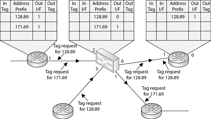
Figure 14-6 MPLS uses tags and tables for routing functions.
Because security requires control over who can access specific resources, more intelligent devices can provide a higher level of protection because they can make more detail-oriented decisions regarding who can access resources. When devices can look deeper into the packets, they have access to more information to make access decisions, which provides more granular access control.
As previously stated, switching makes it more difficult for intruders to sniff and monitor network traffic because no broadcast and collision information is continually traveling throughout the network. Switches provide a security service that other devices cannot provide. VLANs (described in depth in Chapter 13) are an important part of switching networks, because they enable administrators to have more control over their environment and they can isolate users and groups into logical and manageable entities.
Routers
We are going up the chain of the OSI layers while discussing various network devices. Repeaters work at the physical layer, bridges and switches work at the data link layer, and routers work at the network layer. As we go up each layer, each corresponding device has more intelligence and functionality because it can look deeper into the frame. A repeater looks at the electrical signal. The switch can look at the MAC address within the header. The router can peel back the first header information and look farther into the frame and find out the IP address and other routing information. The farther a device can look into a frame, the more decisions it can make based on the information within the frame.
Routers are layer 3, or network layer, devices that are used to connect similar or different networks. (For example, they can connect two Ethernet LANs or an Ethernet LAN to a Frame Relay link.) A router is a device that has two or more interfaces and a routing table, so it knows how to get packets to their destinations. It can filter traffic based on an access control list (ACL), and it fragments packets when necessary. Because routers have more network-level knowledge, they can perform higher-level functions, such as calculating the shortest and most economical path between the sending and receiving hosts.
A router discovers information about routes and changes that take place in a network through its routing protocols (RIP, BGP, OSPF, and others, as discussed in Chapter 11). These protocols tell routers if a link has gone down, if a route is congested, and if another route is more economical. They also update routing tables and indicate if a router is having problems or has gone down.
The router may be a dedicated appliance or a computer running a networking operating system that is dual-homed. When packets arrive at one of the interfaces, the router compares those packets to its ACL. This list indicates what packets are allowed in and what packets are denied. Access decisions are based on source and destination IP addresses, protocol type, and source and destination ports. An administrator may block all packets coming from the 10.10.12.0 network, any FTP requests, or any packets headed toward a specific port on a specific host, for example. This type of control is provided by the ACL, which the administrator must program and update as necessary.
What actually happens inside the router when it receives a packet? Let’s follow the steps:
1. A packet is received on one of the interfaces of a router. The router views the routing data.
2. The router retrieves the destination IP network address from the packet.
3. The router looks at its routing table to see which port matches the requested destination IP network address.
4. If the router does not have information in its table about the destination address, it sends out an ICMP error message to the sending computer indicating that the message could not reach its destination.
5. If the router does have a route in its routing table for this destination, it decrements the TTL value and sees whether the maximum transmission unit (MTU) is different for the destination network. If the destination network requires a smaller MTU, the router fragments the packet.
6. The router changes header information in the packet so that the packet can go to the next correct router, or if the destination computer is on a connecting network, the changes made enable the packet to go directly to the destination computer.
7. The router sends the packet to its output queue for the necessary interface.
Table 14-3 provides a quick review of how routers differ from bridges and switches.
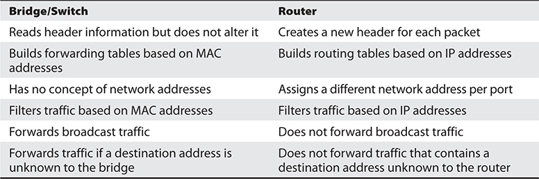
Table 14-3 Main Differences Between Bridges/Switches and Routers
When is it best to use a repeater, bridge, or router? A repeater is used if an administrator needs to expand a network and amplify signals so they do not weaken on longer cables. However, a repeater also extends collision and broadcast domains.
Bridges and switches work at the data link layer and have a bit more intelligence than a repeater. Bridges can do simple filtering and separate collision domains, but not broadcast domains. A switch should be used when an administrator wants to connect multiple computers in a way that reduces traffic congestion and excessive collisions.
A router splits up a network into collision domains and broadcast domains. A router gives more of a clear-cut division between network segments than repeaters or bridges. A router should be used if an administrator wants to have more defined control of where the traffic goes, because more sophisticated filtering is available with routers, and when a router is used to segment a network, the result is more controllable sections.
Gateways
Gateway is a general term for software running on a device that connects two different environments and that many times acts as a translator for them or somehow restricts their interactions. Usually a gateway is needed when one environment speaks a different language, meaning it uses a certain protocol that the other environment does not understand. The gateway can translate mail from one type of mail server and format it so that another type of mail server can accept and understand it, or it can connect and translate different data link technologies such as Fiber Distributed Data Interface (FDDI) to Ethernet (both of which are discussed in Chapter 11).
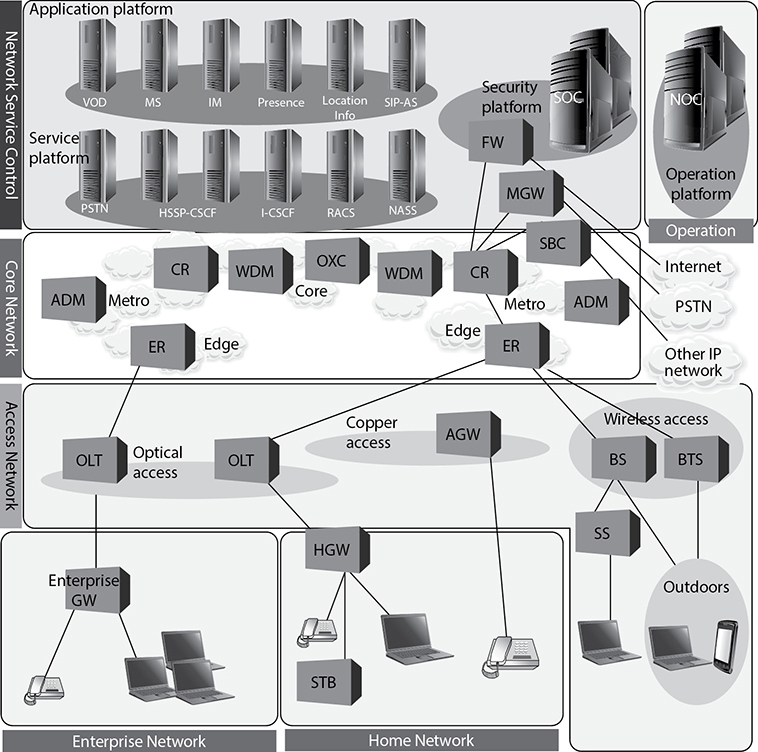
Gateways perform much more complex tasks than connection devices such as routers and bridges. However, some people refer to routers as gateways when they connect two unlike networks (Token Ring and Ethernet) because the router has to translate between the data link technologies. Figure 14-7 shows how a network access server (NAS) functions as a gateway between telecommunications and network connections.
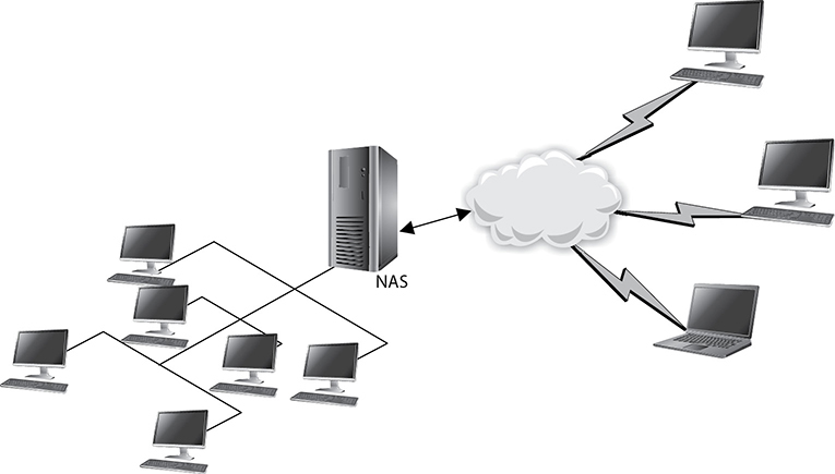
Figure 14-7 Several types of gateways can be used in a network. A NAS is one example.
When networks connect to a backbone, a gateway can translate the different technologies and frame formats used on the backbone network versus the connecting LAN protocol frame formats. If a bridge were set up between an FDDI backbone and an Ethernet LAN, the computers on the LAN would not understand the FDDI protocols and frame formats. In this case, a LAN gateway would be needed to translate the protocols used between the different networks.
A popular type of gateway is an e-mail gateway. Because several e-mail vendors have their own syntax, message format, and way of dealing with message transmission, e-mail gateways are needed to convert messages between e-mail server software. For example, suppose that David, whose corporate network uses Sendmail, writes an e-mail message to Dan, whose corporate network uses Microsoft Exchange. The e-mail gateway converts the message into a standard that all mail servers understand—usually X.400—and passes it on to Dan’s mail server.
Proxy Servers
Proxy servers act as an intermediary between the clients that want access to certain services and the servers that provide those services. As a security professional, you do not want internal systems to directly connect to external servers without some type of control taking place. For example, if users on your network could connect directly to websites without some type of filtering and rules in place, the users could allow malicious traffic into the network or could surf websites your organization deems inappropriate. To prevent this situation, all internal web browsers should be configured to send their web requests to a web proxy server. The proxy server validates that the request is safe and then sends an independent request to the website on behalf of the user. A very basic proxy server architecture is shown in Figure 14-8.
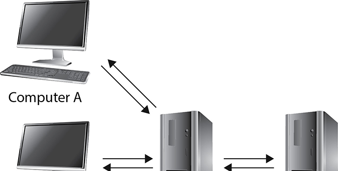
Figure 14-8 Proxy servers control traffic between clients and servers.
The proxy server may cache the response it receives from the server so that when other clients make the same request, the proxy server doesn’t have to make a connection out to the actual web server again but rather can serve up the necessary data directly. This drastically reduces latency and allows the clients to get the data they need much more quickly.
There are different types of proxies that provide specific services. A forwarding proxy is one that allows the client to specify the server it wants to communicate with, as in our scenario earlier. An open proxy is a forwarding proxy that is open for anyone to use. An anonymous open proxy allows users to conceal their IP address while browsing websites or using other Internet services. A reverse proxy appears to the clients as the original server. The client sends a request to what it thinks is the original server, but in reality this reverse proxy makes a request to the actual server and provides the client with the response. The forwarding and reverse proxy functionality seems similar, but as Figure 14-9 illustrates, a forwarding proxy server is commonly on an internal network controlling traffic that is exiting the network. A reverse proxy server is commonly on the network that fulfills clients’ requests; thus, it is handling traffic that is entering its network. The reverse proxy can carry out load balancing, encryption acceleration, security, and caching.

Figure 14-9 Forward vs. reverse proxy services
Web proxy servers are commonly used to carry out content filtering to ensure that Internet use conforms to the organization’s acceptable use policy (AUP). These types of proxies can block unacceptable web traffic, provide logs with detailed information pertaining to the websites specific users visited, monitor bandwidth usage statistics, block restricted website usage, and screen traffic for specific keywords (e.g., porn, confidential, Social Security numbers). The proxy servers can be configured to act mainly as caching servers, which keep local copies of frequently requested resources, allowing organizations to significantly reduce their upstream bandwidth usage and costs while significantly increasing performance.
While the most common use of proxy servers is for web-based traffic, they can be used for other network functionality and capabilities, as in DNS proxy servers. Proxy servers are a critical component of almost every network today. They need to be properly placed, configured, and monitored.
NOTE
The use of proxy servers to allow for online anonymity has increased over the years. Some people use a proxy server to protect their browsing behaviors from others, with the goal of providing personal freedom and privacy. Attackers use the same functionality to help ensure their activities cannot be tracked back to their local systems.
PBXs
Telephone companies use switching technologies to transmit phone calls to their destinations. A telephone company’s central office houses the switches that connect towns, cities, and metropolitan areas through the use of optical fiber rings. So, for example, when Dusty makes a landline phone call from his house, the call first hits the local central office of the telephone company that provides service to Dusty, and then the switch within that office decides whether it is a local or long-distance call and where it needs to go from there. A Private Branch Exchange (PBX) is a private telephone switch that is located on an organization’s property. This switch performs some of the same switching tasks that take place at the telephone company’s central office. The PBX has a dedicated connection to its local telephone company’s central office, where more intelligent switching takes place.
The network devices we’ve covered so far are the building blocks of almost any network architecture. Table 14-4 lists them and points out their important characteristics.
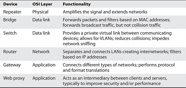
Table 14-4 Main Differences Between Network Devices
A PBX can interface with several types of devices and provides a number of telephone services. The voice data is multiplexed onto a dedicated line connected to the telephone company’s central office. Figure 14-10 shows how data from different data sources can be placed on one line at the PBX and sent to the telephone company’s switching facility.
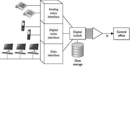
Figure 14-10 A PBX combines different types of data on the same lines.
PBXs use digital switching devices that can control analog and digital signals. While these modern exchanges are more secure than their analog predecessors, that in no way means PBX systems are free from vulnerabilities. Many PBX systems have system administrator passwords that are hardly ever changed. These passwords are set by default; therefore, if 100 companies purchase and implement 100 PBX systems from the PBX vendor ABC and they do not reset the password, a phreaker (a phone hacker) who knows this default password now has access to 100 PBX systems. Once a phreaker breaks into a PBX system, she can cause mayhem by rerouting calls, reconfiguring switches, or configuring the system to provide her and her friends with free long-distance calls. This type of fraud happens more often than most organizations realize because many of them do not closely audit their phone bills. Though the term is not used as much nowadays, phreakers are very much an issue to our telecommunications systems. Toll fraud (as most of their activities are called) associated with PBX systems are estimated to cost over $3 billion in annual losses worldwide, according to the Communications Fraud Control Association’s (CFCA) 2019 Fraud Loss Survey.
PBX systems are also vulnerable to brute force and other types of attacks, in which phreakers use scripts and dictionaries to guess the necessary credentials to gain access to the system. In some cases, phreakers have listened to and changed people’s voice messages. So, for example, when people call Bob and reach his voicemail, they might hear not his usual boring message but a new message that is screaming obscenities and insults.
Unfortunately, many security people do not even think about a PBX when they are assessing a network’s vulnerabilities and security level. This is because telecommunication devices have historically been managed by service providers and/or by someone on the staff who understands telephony. The network administrator is usually not the person who manages the PBX, so the PBX system commonly does not even get assessed. The PBX is just a type of switch and it is directly connected to the organization’s infrastructure; thus, it is a doorway for the bad guys to exploit and enter. These systems need to be assessed and monitored just like any other network device.
So, what should we do to secure PBX systems? Since many of these systems nowadays ride on IP networks, some of the basic security measures will sound familiar. Start by ensuring you know all accounts on the system and that their passwords are strong. Then, ensure that your PBX is updated regularly and that it sits behind your firewall with the appropriate ACLs in place. Other security measures are more specific to a PBX. For example, consider separating your voice and data traffic through these systems by placing them on different VLANs. If one of the VLANs is penetrated, the other could remain secure. Also, limiting the rate of traffic to IP telephony VLANs can slow down an outside attack.
Network Access Control Devices
Network access control (NAC) is any set of policies and controls that we use to, well, control access to our networks. The term implies that we will verify that a device satisfies certain requirements before we let it in. At its simplest level, this could just be user authentication, which was the theme of our discussion of the IEEE 802.1X standard when we were covering wireless network security in Chapter 12. The 802.1X protocol allows devices to connect in a very limited manner (i.e., only to the network authenticator) until we can verify the user credentials it presents.
To fully leverage the power of NAC, however, we should do much more. For starters, we can (and should) authenticate a device. Endpoint/device authentication should be familiar to you because you already use it whenever you establish an HTTPS connection to a web server. When a client requests a secure connection, the server responds with its certificate, which contains its public key issued by a trusted certificate authority (CA). The client then encrypts a secret session key using the server’s public key, so only the server can decrypt it and then establish a symmetrically encrypted secure link. It is possible to configure a NAC device to authenticate itself in a similar manner, but also require the client device to do the same. Obviously, we’d need a certificate (and matching private key) installed on the client device for this to work. An alternative approach to using certificates is to use a hardware Trusted Platform Module (TPM) if the endpoint has one. We discussed TPMs in Chapter 9.
A common use of NAC is to ensure the endpoint is properly configured prior to it being allowed to connect to the network. For example, it is pretty common to check the version of the OS as well as the signatures for the antimalware software. If either of these is not current, the device may be placed in an untrusted LAN segment from which it can download and install the required updates. Once the device meets the access policy requirements, it is allowed to connect to the protected network.
Network Diagramming
In many cases, you cannot capture a full network in a diagram because of the complexity of most organizations’ networks. Sometimes we have a false sense of security when we have a pretty network diagram that we can all look at and be proud of, but let’s dig deeper into why this can be deceiving. From what perspective should you look at a network? Many possibilities exist:
• A cabling diagram that shows how everything is physically connected (coaxial, UTP, fiber) and a wireless portion that describes the WLAN structure
• A network diagram that illustrates the network in infrastructure layers of access, aggregation, edge, and core
• A diagram that illustrates how the various networking routing takes place (VLANs, MPLS connections, OSPF, IGRP, and BGP links)
• A diagram that shows how different data flows take place (FTP, IPSec, HTTP, TLS, L2TP, PPP, Ethernet, FDDI, ATM, etc.)
• A diagram that separates workstations and the core server types that almost every network uses (DNS, DHCP, web farm, storage, print, SQL, PKI, mail, domain controllers, RADIUS, etc.)
• A view of a network based upon trust zones, which are enforced by filtering routers, firewalls, and DMZ structures
• A view of a network based upon its IP subnet structure
But what if you look at a network diagram from a Microsoft perspective, which illustrates many of these things but in forest, tree, domain, and OU containers? Then you need to show remote access connections, VPN concentrators, extranets, and the various MAN and WAN connections. How do we illustrate our IP telephony structure? How do we integrate our mobile device administration servers into the diagram? How do we document our new cloud computing infrastructure? How do we show the layers of virtualization within our database? How are redundant lines and fault-tolerance solutions marked? How does this network correlate and interact with our offsite location that carries out parallel processing? And we have not even gotten to our security components (firewalls, IDS, IPS, DLP, antimalware, content filters, etc.). And in the real world, whatever network diagrams an organization does have are usually out of date because they take a lot of effort to create and maintain.
The point is that a network is a complex beast that cannot really be captured on one piece of paper. Compare it to a human body. When you go into the doctor’s office, you see posters on the wall. One poster shows the circulatory system, one shows the muscles, one shows bones, another shows organs, and another shows tendons and ligaments; a dentist’s office has a bunch of posters on teeth; if you are at an acupuncture clinic, there will be a poster on acupuncture and reflexology points. And then there is a ton of stuff no one makes posters for—hair follicles, skin, toenails, eyebrows—but these are all part of one system.
So what does this mean to the security professional? You have to understand a network from many different aspects if you are actually going to secure it. You start by learning all this network stuff in a modular fashion, but you need to quickly understand how it all works together under the covers. You can be a complete genius on how everything works within your current environment but not fully understand that when an employee connects her iPhone to her company laptop that is connected to the corporate network and uses it as a modem, this is an unmonitored WAN connection that can be used as a doorway by an attacker. Security is complex and demanding, so do not ever get too cocky, and always remember that a diagram is just showing a perspective of a network, not the whole network.
Operation of Hardware
Once you have your network designed and implemented, you need to ensure it remains operational. Keep in mind that one of the aspects of security is availability, which can be compromised not only by adversaries but also by power outages, equipment defects, and human error. Remember that all risks, not just the ones that come from human actors, should be addressed by your risk management program. This ensures that you can select cost-effective controls to mitigate those risks. In the sections that follow, we discuss three specific types of controls that protect the availability of your network components. These control types are redundant electrical power, equipment warranties, and support agreements on the operation of our network components.
Electrical Power
Electrical power is essential to operating IT hardware, which, in turn, runs the software that provides IT services to our organizations. We already discussed this topic generally in Chapter 10, but we now return to it in terms of ensuring our critical systems have redundant power. To understand these power requirements, we need to first become familiar with three key terms that describe electricity:
• Voltage Measured in volts, this tells us what the potential electric force between two points in a circuit could be. You can think of volts as the water pressure inside a pipe.
• Current Measured in amps, this is the actual electric flow through the circuit. If you think of volts as the pressure inside a water pipe, you can think of current as the diameter of a valve attached to it; the bigger the valve, the faster the water can come out.
• Power There are two ways to measure power. We measure electrical power in watts, which we calculate by multiplying voltage by amperage. In other words, if your server rack is running on 240 volts and drawing 9 amps of current, it is consuming 2,160 watts or 2.16 kilowatts (kW). Another related term is kilowatt-hours (kWh), which is simply the amount of power consumed during a 1-hour period. So, that same server rack would draw 2.16 kWh in one hour, or 51.84 kWh in a day (assuming the current draw is constant).
What we actually care about is whether or not we have enough electric power to run our equipment. There are two ways to measure power: apparent and real. You can think of apparent power as the maximum amount of electricity that could get through a circuit in a perfect case. This value is simply the product of the voltage and current of a system, and is measured in volt-amps (VA). So, if you have a 120-volt computer that can draw up to 3 amps, its apparent power would be 360 VA.
Typically, however, the real power drawn by a system is less than its apparent power. This is because of certain complexities of alternating current (AC) circuits that we won’t dive into. Suffice it to say that AC, which is the type of current produced from virtually every power outlet, is constantly changing. This variance means that the real power drawn by a server will be some value, measured in watts, equal to or (much more frequently) lower than the apparent power. Thankfully, we don’t have to calculate this value; most computing equipment is labeled with the real power value in watts (or kilowatts).
Why should you care? Because real power (watts) determines the actual power you purchase from the utility company, the size of any backup generators you might need, and the heat generated by the equipment. Apparent power (VA) is used for sizing wiring and circuit breakers, so the former don’t melt (or worse, catch fire) and the latter don’t trip. The ratio of real power to apparent power is called the work factor, which can never be greater than one (since the denominator is the ideal apparent power).
With all this discussion under our belts, we can now (finally) talk about redundant power, which typically comes in the two forms presented in Chapter 10: uninterruptable power supplies (UPSs) and backup power sources. Suppose one of your organization’s facilities has (what will eventually turn out to be) an extended power outage lasting multiple days. Your business continuity plan (BCP; covered in Chapter 2) should identify your mission-critical systems and determine how long they can remain unavailable before your organizational losses are intolerable. You would have addressed this in your facility planning (Chapter 10) by implementing a backup power source. Typically, there is a period between the start of a power outage and when the backup power source comes online and is usable. This is the amount of time during which your UPS systems will have to keep your critical assets running.
To determine how much power you need from your backup power source, you simply add up the power consumption of your critical assets (in kW), keeping in mind the need for cooling and any other supporting systems. Let’s say this comes out to be 6 kW and your backup source is a generator. Since generators run optimally at 75 percent to 80 percent of their rated loads, you’d need an 8-kW generator or greater. You also want to factor in room for growth, which should be no less than 25 percent, so you end up getting a 10-kW generator. Now, suppose you also get an automatic transfer switch that will start the generator and transfer the load from critical circuits 60 seconds after the outage is detected. How much UPS capacity do you need?
Whereas the real power consumption that you used to estimate your generator needs probably came from actual readings of how many kilowatts your critical servers drew, your apparent power needs are probably higher because they capture peaks in consumption that are averaged out by real power readings. Remember that apparent power is at least as much as (and usually higher than) your real power. If you look at your equipment’s technical descriptions (or labels) you may see a value measured in volt-ampere (VA or kVA), and all you have to do is add up these values and get a UPS that is rated for that value. Alternatively, a good rule of thumb is to multiply your real power by 1.4 kWA (kilowatt-ampere) per kVA. The resulting number of kVAs should give you sufficient UPS capacity until the generator kicks in.
Equipment Warranty
Of course, many other things can go wrong with our assets with or without power outages. Equipment failures due to manufacturing defects are, unfortunately, unavoidable in the long run. The good news is that most original equipment manufacturers (OEMs) provide a three-year warranty against such defects. However, you have to read the fine print and may want to upgrade the protections. Suppose that you have a critical server fail and you can only afford to have it down for 24 hours. The standard warranty includes next-day replacement delivery, so you’re covered, right? Well, not if you factor in the time it’ll take you to reconfigure the server, load up all the data it needs, and put it back into production. Since it is difficult and expensive to get better than next-day support, you may want to build in the cost of having a spare server (or two) in addition to the warranty to ensure you meet your maximum tolerable downtime (MTD).
Most OEMs also offer extended warranties at an additional cost. Depending on your hardware refresh cycle (i.e., how long you will operate equipment before replacing it with new systems), you may want to add one, two, or three more years to the base three-year warranty. This is usually cheaper to purchase when you buy the hardware, as opposed to purchasing it a year or two later. Seven to eight years after the initial purchase, however, warranty offers tend to expire, as the hardware will be too old for the OEM to continue supporting it.
Support Agreements
Even if your hardware doesn’t fail, it could become unavailable (or insufficiently available) with regard to supporting your organizational processes. For example, suppose that a server slows down to the point where your users sit around for several seconds (or even minutes) waiting for a response. This would not only be frustrating but also lead to a loss of productivity that could add up to significant financial losses. If you have a large and well-staffed organization, you probably have a resident expert who can troubleshoot the server and get it back to peak performance. If you don’t have such an expert, what do you do?
Many organizations use support agreements with third parties to deal with issues that are outside the expertise of their IT or security staff. Sometimes this support can be provided by the OEM as part of the purchase of a system. Other times, organizations hire a managed services provider (MSP), who not only responds when things go badly but continuously monitors the systems’ performance to detect and fix problems as early as possible. Most MSPs charge flat monthly fees per device and include 24/7 remote monitoring, maintenance, and, when needed, onsite support. Think of this as an insurance policy against loss of availability.
Endpoint Security
An endpoint is any computing device that communicates through a network and whose principal function is not to mediate communications for other devices on that network. In other words, if a device is connected to a network but is not part of the routing, relaying, or managing of traffic on that network, then it is an endpoint. That definition leaves out all of the network devices we’ve discussed in the preceding sections. Endpoints include devices that you would expect, such as desktops, laptops, servers, smartphones, and tablets. However, they also include other devices that many of us don’t normally think of, such as point of sale (POS) terminals at retail stores, building automation devices like smart thermostats and other Internet of Things (IoT) devices, and sensors and actuators in industrial control systems (ICS).
One of the greatest challenges in dealing with (and securing) endpoints is knowing they are present in the first place. While it would be extremely unusual (not to say frightening) for your routers and switches to unexpectedly drop in and out of the network, this is what mobile devices do by their very nature. The intermittent connectivity of mobile devices is also a problem when it comes to ensuring that they are properly configured and running the correct firmware, OS, and software versions. An approach to dealing with some of these issues is to use network access control (NAC), as discussed earlier in this chapter.
But mobile devices are not the only problem. Our increasing reliance on embedded systems like IoT and ICS devices poses additional challenges. For starters, embedded devices normally have lesser computing capabilities than other endpoints. You usually can’t install security software on them, which means that many organizations simply create security perimeters or bubbles around them and hope for the best. Just to make things even more interesting, IoT and ICS devices oftentimes control physical processes like heating, ventilation, and air conditioning (HVAC) that can have effects on the health and safety of the people in our organizations.
Content Distribution Networks
So far, our discussion of networking has sort of implied that there is a (singular) web server, a (singular) database server, and so on. While this simplifies our discussion of network foundations, protocols, and services, we all know that this is a very rare scenario in all but the smallest networks. Instead, we tend to implement multiples of each service, whether to segment systems, provide redundancy, or both. We may have a couple of web servers connected by a load balancer and interfacing with multiple backend database servers. This sort of redundant deployment can improve performance, but all clients still have to reach the same physical location regardless of where in the world they may be. Wouldn’t it be nice if users in Europe did not have to ride transatlantic cables or satellite links to reach a server in the United States and instead could use one closer to them?
A content distribution network (CDN) consists of multiple servers distributed across a large region, each of which provides content that is optimized for users closest to it. This optimization can come in many flavors. For example, if you were a large streaming video distribution entity like Netflix, you would want to keep your movie files from having to traverse multiple links between routers, since each hop would incur a delay and potential loss of packets (which could cause jitter in the video). Reducing the number of network hops for your video packets would also usually mean having a server geographically closer to the other node, offering you the opportunity to tailor the content for users in that part of the world. Building on our video example, you could keep movies dubbed in Chinese on servers that are in or closer to Asia and those dubbed in French closer to Europe. So when we talk about optimizing content, we can mean many things.
Another benefit of using CDNs is that they make your Internet presence more resistant to distributed denial-of-service (DDoS) attacks. These attacks rely on having a large number of computers flood a server until it becomes unresponsive to legitimate requests. If an attacker can muster a DDoS attack that can send a million packets per second (admittedly fairly small by today’s standards) and aim it at a single server, then it could very well be effective. However, if the attacker tries that against a server that is part of a CDN, the clients will simply start sending their requests to other servers in the network. If the attacker then directs a portion of his attack stream to each server on the CDN in hopes of bringing the whole thing down, the attack will obviously be diffused and would likely require many times more packets. Unsurprisingly, using CDNs is how many organizations protect themselves against DDoS attacks.
Chapter Review
The physical components that make up our networks are foundational to our information systems. Without these cables and switches and routers, nothing else would work. This may seem obvious, but when was the last time you inspected any of them to ensure that they are secure, in good condition, properly configured, and well supported by appropriate third parties? The two classes of threat actors with which we should concern ourselves in this context are attackers and nature. We take care of the first by applying the principles of secure design we’ve discussed throughout the book and, particularly, by physically securing these cables and devices as discussed in Chapter 10. As far as natural threats, we need to be on the lookout for the wear and tear that is natural over time and that can exacerbate small product defects that may not have been apparent during our initial inspections of new products. This boils down to having qualified staff that is augmented, as necessary, by third parties that provide warranty and support services.
Quick Review
• Analog signals represent data as continuously changing wave values, while digital signals encode data in discrete voltage values.
• Digital signals are more reliable than analog signals over a long distance and provide a clear-cut and efficient signaling method because the voltage is either on (1) or not on (0), compared to interpreting the waves of an analog signal.
• Synchronous communications require a timing component but ensure reliability and higher speeds; asynchronous communications require no timing component and are simpler to implement.
• A baseband technology uses the entire communication channel for its transmission, whereas a broadband technology divides the communication channel into individual and independent subchannels so that different types of data can be transmitted simultaneously.
• Coaxial cable has a copper core that is surrounded by a shielding layer and grounding wire, which makes it more resistant to electromagnetic interference (EMI), provides a higher bandwidth, and supports the use of longer cable lengths.
• With twisted-pair cable, the twisting of the wires, the type of insulation used, the quality of the conductive material, and the shielding of the wire determine the rate at which data can be transmitted.
• Fiber-optic cabling carries data as light waves, is expensive, can transmit data at high speeds, is difficult to tap into, and is resistant to EMI and RFI. If security is extremely important, fiber-optic cabling should be used.
• Because it uses glass, fiber-optic cabling has higher transmission speeds that allow signals to travel over longer distances.
• Depending on the material used, network cables may be susceptible to noise, attenuation, and crosstalk.
• Line noise refers to random fluctuations in electrical-magnetic impulses that are carried along a physical medium.
• Attenuation is the loss of signal strength as it travels.
• Crosstalk is a phenomenon that occurs when electrical signals of one wire spill over to the signals of another wire.
• Bandwidth is the amount of information that can theoretically be transmitted over a link within a second.
• Data throughput is the actual amount of data that can actually be carried over a real link.
• A repeater provides the simplest type of connectivity because it only repeats electrical signals between cable segments, which enables it to extend a network.
• A bridge is a LAN device used to connect LAN segments (or VLAN segments) and thus extends the range of a LAN.
• A transparent bridge starts to learn about the network’s environment as soon as it is powered on and continues to learn as the network changes by examining frames and making entries in its forwarding tables.
• Spanning Tree Protocol (STP) ensures that forwarded frames do not circle networks forever, provides redundant paths in case a bridge goes down, assigns unique identifiers to each bridge, assigns priority values to these bridges, and calculates path costs.
• The Shortest Path Bridging (SPB) protocol is defined in IEEE 802.1aq and is more efficient and scalable than STP; it is used in newer bridges.
• Switches are multiport bridges that typically have additional management features.
• Routers are layer 3, or network layer, devices that are used to connect similar or different networks.
• Routers link two or more network segments, where each segment can function as an independent network. A router works at the network layer, works with IP addresses, and has more network knowledge than bridges, switches, or repeaters.
• Gateway is a general term for software running on a device that connects two different environments and that many times acts as a translator for them or somehow restricts their interactions.
• A Private Branch Exchange (PBX) is a private telephone switch that is located on an organization’s property and performs some of the same switching tasks that take place at the telephone company’s central office.
• Proxy servers act as an intermediary between the clients that want access to certain services and the servers that provide those services.
• Network access control (NAC) is any set of policies and controls that restrict access to our networks.
• An endpoint is any computing device that communicates through a network and whose principal function is not to mediate communications for other devices on that network.
• A content distribution network (CDN) consists of multiple servers distributed across a large region, each of which provides content that is optimized for users closest to it.
Questions
Please remember that these questions are formatted and asked in a certain way for a reason. Keep in mind that the CISSP exam is asking questions at a conceptual level. Questions may not always have the perfect answer, and the candidate is advised against always looking for the perfect answer. Instead, the candidate should look for the best answer in the list.
1. Which of the following is true of asynchronous transmission signals?
A. Used for high-speed, high-volume transmissions
B. Robust error checking
C. Used for irregular transmission patterns
D. More complex, costly implementation
2. Which of the following technologies divides a communication channel into individual and independent subchannels?
A. Baseband
B. Broadband
C. Circuit-switched
D. Crosstalk
3. What type of cabling would you use if you needed inexpensive networking in an environment prone to electromagnetic interference?
A. Fiber-optic
B. Unshielded twisted pair (UTP)
C. Plenum
D. Coaxial
4. Which of the following issues would be likeliest to cause problems in a cable tray where large numbers of cables run in parallel and close proximity?
A. Thermal noise
B. Line noise
C. Crosstalk
D. Attenuation
5. What problem is inevitable as the length of a cable run increases?
A. Thermal noise
B. Line noise
C. Crosstalk
D. Attenuation
6. What is the term for the maximum amount of data that actually traverses a given network link?
A. Latency
B. Bandwidth
C. Throughput
D. Maximum transmission unit (MTU)
7. Which protocol ensures that frames being forwarded by switches do not circle networks forever?
A. Open Shortest Path First (OSPF)
B. Border Gateway Protocol (BGP)
C. Intermediate System-to-Intermediate System (IS-IS)
D. Spanning Tree Protocol (STP)
8. Which standard specifically addresses issues in network access control?
A. IEEE 802.1Q
B. IEEE 802.1aq
C. IEEE 802.AE
D. IEEE 802.1X
9. Which of the following would not be considered an endpoint?
A. Point of sale (POS) terminal
B. Industrial control system (ICS)
C. Internet of Things (IoT) device
D. Multiprotocol Label Switching (MPLS) system
10. All of the following are good reasons to implement a content distribution network except for which one?
A. Reduced latency
B. Reduced total cost of ownership (TCO)
C. Protection against distributed denial-of-service (DDoS) attacks
D. Tailoring content to users around the world
Answers
1. C. Asynchronous communications are typically used when data transfers happen at lower volumes and with unpredictable intervals. All other answers describe synchronous signaling, which is best suited for regular, high-volume traffic.
2. B. A broadband technology divides the communication channel into individual and independent subchannels so that different types of data can be transmitted simultaneously. A baseband technology, on the other hand, uses the entire communication channel for its transmission.
3. D. Coaxial cable has a copper core that is surrounded by a shielding layer and grounding wire, which makes it more resistant to electromagnetic interference (EMI). It is significantly cheaper than fiber-optic cable, which is the other EMI-resistant answer listed, while still allowing higher bandwidths.
4. C. Crosstalk is a phenomenon that occurs when electrical signals of one wire spill over to the signals of another wire. The more cables you have in close proximity, the worse this issue can be unless you use shielded cables.
5. D. Attenuation is the loss of signal strength as it travels. Regardless of which type of cabling is used, attenuation is inevitable given a long enough distance, which is why repeaters were invented.
6. C. Data throughput is the actual amount of data that can be carried over a real link. Bandwidth, on the other hand, is the amount of information that can theoretically be transmitted over a link within a second.
7. D. Spanning Tree Protocol (STP) ensures that forwarded frames do not circle networks forever, provides redundant paths in case a bridge goes down, assigns unique identifiers to each bridge, assigns priority values to these bridges, and calculates path costs. The other answers are all routing (layer 3) protocols.
8. D. The 802.1X protocol allows devices to connect in a very limited manner (i.e., only to the network authenticator) until the device and/or user can be authenticated. The other standards listed all pertain to layer 2 bridging and security.
9. D. An endpoint is any computing device that communicates through a network and whose principal function is not to mediate communications for other devices on that network. MPLS functionality is built into networking devices to help them move packets between endpoints more efficiently.
10. B. A content distribution network (CDN) consists of multiple servers distributed across a large region, each of which provides content that is optimized for users closest to it. This improves latency and localization. The very distributed nature of the CDN also provides DDoS protections. It all comes at significant costs and increases the complexity of deploying systems and content, which may require additional organizational resources apart from the service itself.