
CHAPTER 13
Securing the Network
This chapter presents the following:
• Secure networking
• Secure protocols
• Multilayer protocols
• Converged protocols
• Micro-segmentation
More connections to more devices means more vulnerabilities.
Having developed a foundational understanding of networking technologies, we now turn our attention to building secure networks upon this foundation. In this chapter, we circle back to the core networking and service protocols introduced in Chapter 11 and discuss the threats against them and how to mitigate those threats. This discussion is grounded in the secure design principles covered in Chapter 9. We’ll take the same approach as we expand our scope of interest from those core protocols and services to include other services, such as e-mail, that are critical to modern networks.
These networks are not as neatly divided as the OSI model could lead us to believe. Increasingly, we are relying on multilayer and converged protocols where concepts from different layers and even network components overlap in ways that have important security implications. The goal of this chapter is to show how, through a thoughtful application of secure protocols and best practices, we can secure our networks and the services they provide.
Applying Secure Design Principles to Network Architectures
A network architecture is just a model of a network. Like any model, it is not 100 percent representative of reality and uses abstractions to simplify some details so that we can focus on the others. By ignoring the little details (for now), we make it easier on ourselves to focus on the more important elements. For example, before we decide how many web servers we need and which operating systems and software we need to run on them, we should first identify the classes of servers and where we would put them. We might have a set of externally accessible servers for our web presence, but we may also need some servers that are for internal use only by all employees, and yet another set that is only for web developers. Where do we put each set and how might we need different controls for them? Maybe we need a demilitarized zone (DMZ), an internal sharing cluster, and a development virtual local area network (VLAN), each with specific sets of controls meant to mitigate their differing risk profiles. A network architecture allows us to answer these high-level questions before we start configuring any boxes.
Now, once we go through all the trouble of coming up with an architecture that works, we shouldn’t have to reinvent the wheel. Network architectures also serve as templates for future systems. What’s more, they can be codified and shared among similar organizations to reduce work and ensure we all follow best practices. Even if a lot of the details are different, a sound architecture can be reused time and again.
Many of these best practices relate to security. Since we intend our architectures to be reusable, it is imperative that we apply secure design principles when we implement them. In the sections that follow, we will discuss a (wide) variety of networking concepts and technologies that you will need to understand to implement secure design principles in network architectures. Periodically, we circle back and discuss some of these important secure design principles. It is important to note that there is no one-size-fits-all solution in this effort, so you will have to be selective about which of these principles you apply in any specific situation. Still, as a CISSP, you are expected to be conversant with all of them.
Let’s start by reviewing the 11 secure design principles we covered in Chapter 9 and look at how they apply to network architectures.
• Threat modeling Everything we do in cybersecurity should be grounded in a good understanding of the threats we face. In this chapter, we focus our attention on network security, so we’ll illustrate the threats we face as we discuss the various technologies and protocols involved in operating and securing our networks.
• Least privilege Traffic should be allowed to flow between any two points that are required to communicate in order to satisfy a valid organizational requirement, and nowhere else. We cover this in depth when we address network segmentation later in this chapter.
• Defense in depth While some IT and security professionals equate this principle with having a DMZ for public-facing servers, the principle applies throughout the network and requires that we build concentric defenses around our most valuable assets.
• Secure defaults Perhaps the simplest illustration of this principle as it applies to our networks is ensuring firewalls’ default configurations are to deny all traffic from any source to any destination (deny all all). However, the principle should apply throughout our network and be consistent with least privilege.
• Fail securely The key to applying this principle is asking two questions: What happens when this network system fails? What happens when a packet doesn’t match an “allow” rule on the firewall? (Hint: it should not be allowed through.)
• Separation of duties Speaking of firewall (and other security appliance) rules, who is in charge of those in your organization? Any sensitive duties should be split up among vetted staff members. At a minimum, if you don’t have enough staff, everybody’s sensitive work should be regularly checked by someone else.
• Keep it simple Unless you are architecting a global network for a multinational corporation, you should try to develop an architecture that can be depicted in a single PowerPoint slide and still describe all the important components.
• Zero trust Services and traffic on your network should all be authenticated and encrypted. When two servers are part of a system (e.g., the web server and its backend database), they should authenticate each other and have rules around what requests each is allowed to make of the other.
• Privacy by design Encrypting your network traffic is a good start toward protecting privacy, but where is the data being collected and for what purpose? For example, as we prepare for auditability (see the next principle), we need to ensure that we are not casting too wide of a net in terms of the data we log.
• Trust but verify Everything that happens on the network should be auditable, meaning that there should be a record of who is talking with whom, when, and why. This is normally done by ensuring logs are properly configured and protected against tampering or accidental loss.
• Shared responsibility Odds are that your network architecture will include at least a handful of service providers. Whether these are Internet service providers, cloud service providers, or managed services providers, it is critical to agree on who has responsibility over which aspects of your network.
 EXAM TIP
You should be prepared to map the various secure design principles to specific scenarios.
With these principles in mind, let’s look at specific ways in which we can assess and implement network architectures securely.
Secure Networking
The most prevalent networking standards and protocols we use today (Ethernet, TCP/IP, and so on) were born decades ago (before many of us). Back then, the world was kinder and gentler (at least in the digital realm) and security just wasn’t the sort of thing folks thought about when it came to computers and networks. With the explosion of the Internet came immense opportunities for both the law abiding and the criminals. The need for secure networking became apparent, but it was too late. We’ve been trying to catch up ever since by bolting security onto insecure technologies. One of the most common ways of securing our networks is through the use of encryption, particularly in trusted tunnels through untrusted networks.
Link Encryption vs. End-to-End Encryption
In each of the networking technologies discussed in this chapter, encryption can be performed at different levels, each with different types of protection and implications. Two general modes of encryption implementation are link encryption and end-to-end encryption. Link encryption encrypts all the data along a specific communication path, as in a satellite link, a terrestrial T3 leased line, or even between hosts on the same LAN. Because link encryption happens at layers 1 and 2, not only is the user information encrypted, but the (layer 3 and higher) headers, trailers, addresses, and routing data that are part of the packets are also encrypted. The only traffic not encrypted in this technology is the data link control messaging information, which includes instructions and parameters that the different link devices use to synchronize communication methods. Reading this information won’t give an attacker any insights into what is being transmitted or where it is ultimately going.
End-to-end encryption (E2EE) occurs at the session layer (or higher), which means the headers, addresses, routing information, and trailer information are not encrypted, enabling attackers to learn more about a captured packet and where it is headed. Transport Layer Security (TLS), which we will discuss shortly, is the most common example of E2EE. Because the routing information is sent in plaintext, attackers can perform traffic analysis to learn details about the network, such as which hosts play which roles in it.
Link encryption, which is sometimes called online encryption, is usually provided by service providers and is incorporated into network protocols. All of the information is encrypted, and the packets must be decrypted at each hop so the router, or other intermediate device, knows where to send the packet next. The router must decrypt the header portion of the packet, read the routing and address information within the header, and then re-encrypt it and send it on its way.
With end-to-end encryption, the packets do not need to be decrypted and then encrypted again at each hop because the headers and trailers are not encrypted. The devices in between the origin and destination just read the necessary routing information and pass the packets on their way.
End-to-end encryption is usually initiated by the user of the originating computer. It provides more flexibility for the user to be able to determine whether or not certain messages will get encrypted. It is called “end-to-end encryption” because the message stays encrypted from one end of its journey to the other. Link encryption has to decrypt the packets at every device between the two ends.
Link encryption occurs at the data link and physical layers, as depicted in Figure 13-1. Hardware encryption devices interface with the physical layer and encrypt all data that passes through them. Because no part of the data is available to an attacker, the attacker cannot learn basic information about how data flows through the environment. This is referred to as traffic-flow security.
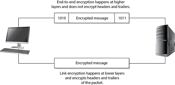
Figure 13-1 Link and end-to-end encryption happen at different OSI layers.
 NOTE
NOTE
A hop is a device that helps a packet reach its destination. It is usually a router that looks at the packet address to determine where the packet needs to go next. Packets usually go through many hops between the sending and receiving computers.
Advantages of end-to-end encryption include the following:
• It provides more flexibility to the user in choosing what gets encrypted and how.
• Higher granularity of functionality is available because each application or user can choose specific configurations.
• Each hop device on the network does not need to have a key to decrypt each packet.
The disadvantage of end-to-end encryption is the following:
• Headers, addresses, and routing information are not encrypted, and therefore not protected.
Advantages of link encryption include the following:
• All data is encrypted, including headers, addresses, and routing information.
• Users do not need to do anything to initiate it. It works at a lower layer in the OSI model.
Disadvantages of link encryption include the following:
• Key distribution and management are more complex because each hop device must receive a key, and when the keys change, each must be updated.
• Packets are decrypted at each hop; thus, more points of vulnerability exist.
TLS
The most prevalent form of end-to-end encryption is Transport Layer Security (TLS). TLS is a security protocol that provides confidentiality and data integrity for network communications. It replaced the (now insecure) Secure Sockets Layer (SSL) standard. These two protocols coexisted for many years, and most people thought that there were very few differences between SSL and TLS (TLS is currently in version 1.3). However, the Padding Oracle On Downgraded Legacy Encryption (POODLE) attack in 2014 was the death knell of SSL and demonstrated that TLS was superior security-wise. The key to the attack was to force SSL to downgrade its security, which was allowed for the sake of interoperability.
EXAM TIP
Because SSL and TLS were (for a time) very closely related, the terms are sometimes still used interchangeably to describe network encryption in general. However, the SSL protocol has been insecure for many years and should not be the correct answer to an encryption question (unless it is asking for an insecure protocol).
Backward compatibility has long been a thorn in the side of those of us trying to improve cybersecurity. TLS 1.3 represents a switch to a focus on security, which shows in the limited number of cipher suites that it supports (just five). This means attackers can no longer trick a server into using an insecure cryptosystem during the connection establishment negotiation. One of the key features of TLS 1.3 is that the handshake used to establish a new connection requires only one client message to the server and one response from the server. There’s a lot that happens in there, though, so let’s take a look at a summarized version of this handshake.
1. Client “Hello” message, which includes
• A list of cipher suites and protocols supported by the client
• Client inputs for the key exchange
2. Server “Hello” message, which includes
• The server’s selection of cipher suite and protocol version
• Server inputs for the key exchange
3. Server authentication, which includes
• The server’s digital certificate
• Proof that the server owns the certificate’s private key
4. (Optionally) Client authentication, which includes
• The client’s digital certificate
• Proof that the client owns the certificate’s private key
NOTE
While TLS 1.3 minimizes the plaintext information transferred between hosts, TLS 1.2 (and earlier) passes a lot more information in the clear, potentially including the server name (e.g., www.goodsite.com).
As mentioned, TLS 1.3 has dramatically reduced the number of recommended cipher suites from 37 (in previous versions) to just five. This is an important improvement because some of those 37 suites were known (or suspected) to be vulnerable to cryptanalysis. By reducing the suites to five and ensuring these provide strong protection, TLS 1.3 makes it harder for attackers to downgrade the security of a system by forcing a server to use a weaker suite. The allowed suites in the latest version of TLS are as follows:
• TLS_AES_256_GCM_SHA384 The encryption algorithm here is AES with a 256-bit key in Galois/Counter Mode (GCM). GCM is a mode of operation that provides message authentication. The hashing algorithm is SHA-384. This suite provides the best protection but requires the most computing resources.
• TLS_AES_128_GCM_SHA256 This suite is almost identical to the preceding one, but saves on resources by using a smaller 128-bit key for encryption and a slightly faster SHA-256 for hashing. It is ideally suited for systems with hardware support for encryption.
• TLS_AES_128_CCM_SHA256 In this suite, AES (again, with a 128-bit key) runs in Counter mode with CBC-MAC (CCM), which uses 16-byte tags to provide message authentication (much like GCM does).
• TLS_AES_128_CCM_8_SHA256 This suite is almost identical to the preceding one, but Counter mode with CBC-MAC uses 8-byte tags (instead of 16-byte ones), which makes it better suited for embedded devices.
• TLS_CHACHA20_POLY1305_SHA256 The ChaCha stream cipher (doing 20 rounds), combined with the Poly1305 message authentication code (MAC), is a cipher suite that is a good choice for software-based encryption systems. Many modern systems rely on hardware-based encryption, so the authors of TLS 1.3 wanted to ensure the recommended suites supported multiple devices. Besides, it just makes sense to have at least one encryption algorithm that is not AES.
We already discussed AES (and briefly mentioned ChaCha20) in Chapter 8, and CCM in Chapter 12, but this is the first time we bring up GCM and Poly1305. These are approaches to provide authenticated symmetric key encryption. Authenticated encryption (AE) provides assurances that a message was not modified in transit and could only come from a sender who knows the secret key. This is similar to the MAC approach discussed in Chapter 8 but is applied to stream ciphers. TLS 1.3 takes the AE concept to the next level in what is known as authenticated encryption with additional data (AEAD). AEAD essentially computes the MAC over both ciphertext and plaintext when these are sent together. For example, when sending network traffic, there are certain fields (e.g., source and destination addresses) that cannot be encrypted. An attacker could replay an encrypted message later using a different packet, but if we’re using AEAD (as TLS 1.3 requires), this bogus packet would automatically be discarded.
Another key feature of TLS 1.3 (which was optional in TLS 1.2 and prior) is its use of ephemeral keys, which are only used for one communication session and then discarded, using the Diffie-Hellman Ephemeral (DHE) algorithm. This provides forward secrecy (sometimes called perfect forward secrecy), which means that if attackers were somehow able to crack or otherwise obtain the secret key, it would only give them the ability to decrypt a small portion of the ciphertext. They wouldn’t be able to decrypt everything going forward.
While we focused on TLS 1.3 in this section, it is worth noting that, as of this writing, the Internet Society reports that only 58 percent of the world’s top 1,000 websites support this latest version. What does this mean to you? You should balance the enhanced security of this protocol with the needs of your stakeholders. If you are not on TLS 1.3 yet, you may want to ask what percentage of your user base would not be able to communicate securely if you switched. All major browsers support it, so odds are that you’d be in good shape. But even if you’re still on TLS 1.2, keep in mind that most of the features described in this section that make 1.3 so much better are optional in the previous version. This should give you a path to gradually improve your security while taking care of your stakeholders. Whatever your situation, TLS is probably the most important encryption technology for securing our networks, particularly our virtual private ones.
NOTE
TLS 1.0 and TLS 1.1 were never formally deprecated but are widely considered insecure.
VPN
A virtual private network (VPN) is a secure, private connection through an untrusted network, as shown in Figure 13-2. It is a private connection because the encryption and tunneling protocols are used to ensure the confidentiality and integrity of the data in transit. It is important to remember that VPN technology requires a tunnel to work and it assumes encryption.

Figure 13-2 A VPN provides a virtual dedicated link between two entities across a public network.
We need VPNs because we send so much confidential information from system to system and network to network. The information can be credentials, bank account data, Social Security numbers, medical information, or any other type of data we do not want to share with the world. The demand for securing data transfers has increased over the years, and as our networks have increased in complexity, so have our VPN solutions.
Point-to-Point Tunneling Protocol
One of the early approaches to building VPNs was Microsoft’s Point-to-Point Tunneling Protocol (PPTP), which uses Generic Routing Encapsulation (GRE) and TCP to encapsulate Point-to-Point Protocol (PPP) connections and extend them through an IP network (running on TCP port 1723, by default). Since most Internet-based communication first started over telecommunication links, the industry needed a way to secure PPP connections, which were prevalent back then. The original goal of PPTP was to provide a way to tunnel PPP connections through an IP network, but most implementations included security features also since protection was becoming an important requirement for network transmissions at that time. PPTP, like many security protocols, did not age well and is now considered insecure and obsolete.
Layer 2 Tunneling Protocol
The Layer 2 Tunneling Protocol (L2TP), currently in version 3, is a combination of Cisco’s Layer 2 Forwarding (L2F) protocol and Microsoft’s PPTP. L2TP tunnels PPP traffic over various network types (IP, ATM, X.25, etc.); thus, it is not just restricted to IP networks as PPTP was. PPTP and L2TP have very similar focuses, which is to get PPP traffic to an end point that is connected to some type of network that does not understand PPP. Unlike PPTP, L2TP runs on UDP (default port 1701), which makes it a bit more efficient. However, just like PPTP, L2TP does not actually provide much protection for the PPP traffic it is moving around, but it integrates with protocols that do provide security features. L2TP inherits PPP authentication and integrates with IPSec to provide confidentiality, integrity, and potentially another layer of authentication.
It can get confusing when several protocols are involved with various levels of encapsulation, but if you do not understand how they work together, you cannot identify if certain traffic links lack security. To figure out if you understand how these protocols work together and why, ask yourself these questions:
1. If the Internet is an IP-based network, why do we even need PPP?
2. If L2TP does not actually secure data, then why does it even exist?
3. If a connection is using IP, PPP, and L2TP, where does IPSec come into play?
Let’s go through the answers together. Let’s say that you are a remote user and work from your home office. You do not have a dedicated link from your house to your company’s network; instead, your traffic needs to go through the Internet to be able to communicate with the corporate network. The line between your house and your ISP is a point-to-point telecommunications link, one point being your home router and the other point being the ISP’s switch, as shown in Figure 13-3. Point-to-point telecommunication devices do not understand IP, so your router has to encapsulate your traffic in a protocol the ISP’s device will understand—PPP. Now your traffic is not headed toward some website on the Internet; instead, it has a target of your company’s corporate network. This means that your traffic has to be “carried through” the Internet to its ultimate destination through a tunnel. The Internet does not understand PPP, so your PPP traffic has to be encapsulated with a protocol that can work on the Internet and create the needed tunnel.
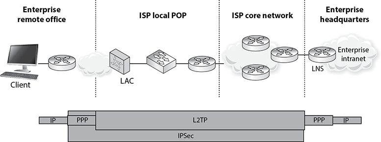
Figure 13-3 IP, PPP, L2TP, and IPSec can work together.
So your IP packets are wrapped up in PPP, and are then wrapped up in L2TP. But you still have no encryption involved, so your data is actually not protected. This is where IPSec comes in. IPSec is used to encrypt the data that will pass through the L2TP tunnel. Once your traffic gets to the corporate network’s perimeter device, it will decrypt the packets, take off the L2TP and PPP headers, add the necessary Ethernet headers, and send these packets to their ultimate destination.
Here are the answers to our questions:
1. If the Internet is an IP-based network, why do we even need PPP?Answer: The point-to-point line devices that connect individual systems to the Internet do not understand IP, so the traffic that travels over these links has to be encapsulated in PPP.
2. If L2TP does not actually secure data, then why does it even exist?Answer: It extends PPP connections by providing a tunnel through networks that do not understand PPP.
3. If a connection is using IP, PPP, and L2TP, where does IPSec come into play?Answer: IPSec provides the encryption, data integrity, and system-based authentication.
Here is another question: Does all of this PPP, L2TP, and IPSec encapsulation have to happen for every single VPN used on the Internet? No, only when connections over point-to-point connections are involved. When two gateway routers are connected over the Internet and provide VPN functionality, they only have to use IPSec.
Internet Protocol Security
Internet Protocol Security (IPSec) is a suite of protocols that was developed to specifically protect IP traffic. IPv4 does not have any integrated security, so IPSec was developed to “bolt onto” IP and secure the data the protocol transmits. Where L2TP works at the data link layer, IPSec works at the network layer of the OSI model.
The main protocols that make up the IPSec suite and their basic functionality are as follows:
• Authentication Header (AH) Provides data integrity, data-origin authentication, and protection from replay attacks
• Encapsulating Security Payload (ESP) Provides confidentiality, data-origin authentication, and data integrity
• Internet Security Association and Key Management Protocol (ISAKMP) Provides a framework for security association creation and key exchange
• Internet Key Exchange (IKE) Provides authenticated keying material for use with ISAKMP
AH and ESP can be used separately or together in an IPSec VPN configuration. The AH protocols can provide data-origin authentication (system authentication) and protection from unauthorized modification, but do not provide encryption capabilities. If the VPN needs to provide confidentiality, then ESP has to be enabled and configured properly.
When two routers need to set up an IPSec VPN connection, they have a list of security attributes that need to be agreed upon through handshaking processes. The two routers have to agree upon algorithms, keying material, protocol types, and modes of use, which will all be used to protect the data that is transmitted between them.
Let’s say that you and Juan are routers that need to protect the data you will pass back and forth to each other. Juan sends you a list of items that you will use to process the packets he sends to you. His list contains AES-128, SHA-1, and ESP tunnel mode. You take these parameters and store them in a security association (SA). When Juan sends you packets one hour later, you will go to this SA and follow these parameters so that you know how to process this traffic. You know what algorithm to use to verify the integrity of the packets, the algorithm to use to decrypt the packets, and which protocol to activate and in what mode. Figure 13-4 illustrates how SAs are used for inbound and outbound traffic.
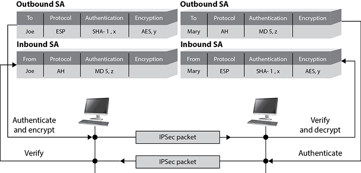
Figure 13-4 IPSec uses security associations to store VPN parameters.
NOTE
The U.S. National Security Agency (NSA) uses a protocol encryptor that is based upon IPSec. A HAIPE (High Assurance Internet Protocol Encryptor) is a Type 1 encryption device that is based on IPSec with additional restrictions, enhancements, and capabilities. A HAIPE is typically a secure gateway that allows two enclaves to exchange data over an untrusted or lower-classification network. Since this technology works at the network layer, secure end-to-end connectivity can take place in heterogeneous environments. This technology has largely replaced link layer encryption technology implementations.
IPSec can be configured to provide transport adjacency, which just means that more than one security protocol (ESP and AH) is used in a VPN tunnel. IPSec can also be configured to provide iterated tunneling, in which an IPSec tunnel is tunneled through another IPSec tunnel, as shown in the following diagram. Iterated tunneling would be used if the traffic needed different levels of protection at different junctions of its path. For example, if the IPSec tunnel started from an internal host and terminated at an internal border router, this may not require encryption, so only the AH protocol would be used. But when that data travels from that border router throughout the Internet to another network, then the data requires more protection. So the first packets travel through a semisecure tunnel until they get ready to hit the Internet and then they go through a very secure second tunnel.

The most common implementation types of TLS VPN are as follows:
• TLS portal VPN An individual uses a single standard TLS connection to a website to securely access multiple network services. The website accessed is typically called a portal because it is a single location that provides access to other resources. The remote user accesses the TLS VPN gateway using a web browser, is authenticated, and is then presented with a web page that acts as the portal to the other services.
• TLS tunnel VPN An individual uses a web browser to securely access multiple network services, including applications and protocols that are not web-based, through a TLS tunnel. This commonly requires custom programming to allow the services to be accessible through a web-based connection.
Since TLS VPNs are closer to the application layer, they can provide more granular access control and security features compared to the other VPN solutions. But since they are dependent on the application layer protocol, there are a smaller number of traffic types that can be protected through this VPN type.
One VPN solution is not necessarily better than the other; they just have their own focused purposes:
• L2TP is used when a PPP connection needs to be extended through a network.
• IPSec is used to protect IP-based traffic and is commonly used in gateway-to-gateway connections.
• TLS VPN is used when a specific application layer traffic type needs protection.
Secure Protocols
TLS may be one of the most talked-about technologies when it comes to network security. Still, there are other protocols, and other applications of TLS, that you should know. This section addresses each of the main network services, web, DNS, and e-mail. Let’s start with how we secure web services.
Web Services
Many people hear the term “web services” and think of websites and the web servers that do the work behind the scenes. In reality, however, this is but a portion of what the term actually covers. A web service is a client/server system in which clients and servers communicate using HTTP over a network such as the Internet. Sure, this definition covers static web pages written in HTML being served out of an old Apache server somewhere, but it can also cover much more.
For example, suppose you are a retailer and don’t want to pay for a huge storage space for merchandise that may or may not sell anytime soon. You could implement a just-in-time logistics system that keeps track of your inventory and past selling patterns, and then automatically order merchandise so that it arrives just before you start running low. This kind of system is typically implemented using a business-to-business (B2B) web service and is depicted in Figure 13-5. Each icon in the figure represents a distinct web service component.

Figure 13-5 Example just-in-time logistics B2B web service
When we look at web services this way, it becomes clear that we have much more to worry about than simply the interaction between customers and our website. Let’s look at ways in which we could implement some of the secure design principles in this example. The following list is meant to be illustrative, not all-inclusive:
• Least privilege The forecasting service should have read-only access to some of the data in the inventory system. It doesn’t need any additional access.
• Secure defaults The inventory service should refuse all connection requests from any endpoint other than those explicitly authorized (point of sale and forecasting). If any other connections are required, those should be added as exceptions after a careful review.
• Fail securely The forecasting service has the ability to spend money by placing orders from suppliers. It should not process any order that is malformed or otherwise fails any checks.
• Separation of duties The forecasting service can place orders but cannot receive shipments and update inventory. Ordering and receiving should be two separate duties performed by different people/systems to mitigate the risk of fraud.
• Zero trust Before any two components collaborate, they should both be required to authenticate with each other and encrypt all communications. This is particularly true (and the authentication protocol should be more rigorous) when dealing with external parties like customers and suppliers.
• Privacy by design Customer information should not be shared outside the point-of-sale (PoS) system, particularly since the other two internal systems (inventory and forecasting) communicate with an external third party. This example is overly simplistic, but the point is that customer data should be limited to the components that absolutely need it.
• Trust but verify All components (with the possible exception of the user) should generate logs that are sufficient to detect attacks or errors. Ideally, these logs are centrally collected to make them easier to correlate and harder to tamper with.
• Shared responsibility The security obligations of the organization and of the supplier should be codified in a legally binding contract and audited periodically.
Again, the list is not exhaustive, but it should give you an idea of how the secure design principles can be applied to a web services scenario. You should be prepared to do likewise with a variety of other scenarios for the CISSP exam.
How are these web services actually delivered? The key is to focus on what service is being delivered, and not on how it is implemented or where it is hosted (as long as it is available). A service-oriented architecture (SOA) describes a system as a set of interconnected but self-contained components that communicate with each other and with their clients through standardized protocols. These protocols, called application programming interfaces (APIs), establish a “language” that enables a component to make a request from another component and then interpret that second component’s response. The requests that are defined by these APIs correspond to discrete business functions (such as estimated shipping costs to a postal code) that can be useful by themselves or can be assembled into more complex business processes. An SOA has three key characteristics: self-contained components, a standardized protocol (API) for requests/responses, and components that implement business functions.
SOAs are commonly built using web services standards that rely on HTTP as a standard communication protocol. Examples of these are SOAP (which used to stand for the Simple Object Access Protocol) and the Representational State Transfer (REST) architectures. Let’s look at these three (HTTP, SOAP and REST) in turn.
Hypertext Transfer Protocol
HTTP is a TCP/IP-based communications protocol used for transferring resources (e.g., HTML files and images) between a server and a client. It also allows clients to send queries to the server. The two basic features of HTTP are that it is connectionless and stateless. Connectionless protocols do not set up a connection (obviously) and instead send their messages in a best-effort manner. They rely on some other protocol (in this case TCP) to ensure the message gets across. Stateless means that the server is amnesiac; it doesn’t remember any previous conversations with any clients. Thus, whatever is needed for the server to “remember” has to be provided with each request. This is a role commonly played by session identifiers and cookies.
NOTE
A cookie is just a small text file containing information that only one website can write or read.
Uniform Resource Identifiers
A foundational component of HTTP is the use of the uniform resource identifier (URI), which uniquely identifies a resource on the Internet. A typical URI looks like this: http://www.goodsite.com:8080/us/en/resources/search.php?term=cissp. Let’s look at its components in sequence:
1. Scheme This is another name for the protocol being used (e.g., HTTP or HTTPS) and ends in a colon (:).
2. Authority There are three possible subcomponents here, but the second is the most prevalent:
• Username (optional) (and optional password, separated by a colon) followed by an at (@) symbol.
• Host in either hostname (e.g., www.goodsite.com) or IP address format.
• Port number (optional), preceded by a colon (e.g., :8080). Note that port 80 is assumed for HTTP schemes and port 443 for HTTPS schemes.
3. Path The path to the requested resource on the server. If the path is not specified by the client, it is assumed to be a single slash (/), which is the default document at the root of the website (e.g., the homepage). Subdirectories are indicated as they are in Linux/Unix by successive slashes (e.g., /us/en/resources/search.php).
4. Query (optional) An attribute-value pair preceded by a question mark (?) (e.g., ?term=cissp). Each additional pair is separated from the previous one by an ampersand (&).
Request Methods
HTTP uses a request-response model in which the client requests one or more resources from the server, and the latter provides the requested resources (assuming, of course, they are available to the client). The protocol defines two request methods: GET and POST. The main difference for our discussion is that a GET request must include all parameters in the URI, while POST allows us to include additional information (e.g., parameters) in the body of the request, where it will not be revealed in the URI. So, in the previous example we can safely guess that the method used was GET because we see the search term (cissp) in the URI.
Hypertext Transfer Protocol Secure
HTTP Secure (HTTPS) is HTTP running over Transport Layer Security (TLS). Ensuring that all your web services require HTTPS is probably the most important security control you can apply to them. Recall that unencrypted requests can provide an awful lot of sensitive data, including credentials, session IDs, and URIs. Ideally, you require TLS 1.3 on all your web servers and ensure they do not allow unencrypted communications (by enforcing secure defaults).
An important consideration before you jump to HTTPS everywhere is whether you want to perform deep packet analysis on all your internal traffic. If you force use of HTTPS, you will need to deploy TLS decryption proxies, which can be pricey and require careful configuration on all your endpoints. The way these proxies work is by performing what is essentially a (benign) man-in-the-middle attack in which they terminate the clients’ secure sessions and establish the follow-on session to their intended server. This allows the proxy to monitor all HTTPS traffic, which provides a measure of defense in depth but may pose some challenges to the privacy by design principle. Many organizations deal with this challenge by whitelisting connections to certain types of servers (e.g., healthcare and financial services organizations), while intercepting all others.
SOAP
SOAP is a messaging protocol that uses XML over HTTP to enable clients to invoke processes on a remote host in a platform-agnostic way. SOAP was one of the first SOAs to become widely adopted. SOAP consists of three main components:
• A message envelope that defines the messages that are allowed and how they are to be processed by the recipient
• A set of encoding rules used to define data types
• Conventions regarding what remote procedures can be called and how to interpret their responses
SOAP security is enabled by a set of protocol extensions called the Web Services Security (WS-Security or WSS) specification, which provides message confidentiality, integrity, and authentication. Note that, in keeping with HTTP’s stateless nature, the focus here is on message-level security. Confidentiality is provided through XML encryption, integrity through XML digital signatures, and single-message authentication through security tokens. These tokens can take on various forms (the specification is intentionally broad here), which include username tokens, X.509 digital certificates, SAML assertions, and Kerberos tickets (we’ll cover the last two in Chapter 17).
One of the key features of SOAP is that the message envelope allows the requester to describe the actions that it expects from the various nodes that respond. This feature supports options such as routing tables that specify the sequence and manner in which a series of SOAP nodes will take action on a given message. This can make it possible to finely control access as well as efficiently recover from failures along the way. This richness of features, however, comes at a cost: SOAP is not as simple as its name implies. In fact, SOAP systems tend to be fairly complex and cumbersome, which is why many web service developers prefer more lightweight options like REST.
Representational State Transfer
Unlike SOAP, which is a messaging protocol, Representational State Transfer (REST) is an architectural pattern used to develop web services using a variety of languages. In REST, HTTP is used to provide an API that allows clients to make programmatic requests from servers. For example, a client of a RESTful service could insert a new user record using the HTTP POST method (which lets you send additional information in the body of the request) by sending the following URI: https://www.goodsite.com/UserService/Add/1. The server would know to read the body of the POST to get the new user’s details, create it, and then send a HTTP confirmation (or error). As you can see, REST essentially creates a programming language in which every statement is an HTTP URI.
Because every interaction with the system is spelled out in the URI, it is essential to use HTTPS as a secure default communications protocol. Of course, in keeping with the principle of zero trust, we want to authenticate clients and servers to each other, as well as put limits on what resources are available to each client. Another good security practice for RESTful services, which applies to any software system, is to validate all inputs before processing them. This mitigates a large number of possible injection attacks in which the adversary deliberately provides malformed inputs in order to trigger a system flaw.
Domain Name System
We covered the Domain Name System (DNS) in a fair amount of detail back in Chapter 11. Let’s return to it now in the context of its role in helping us to secure our networks. Early on in its history, DNS was most commonly targeted by attackers to hijack requests, redirecting the unwitting requesters to malicious hosts instead of the legitimate ones they were seeking. While this is still a concern that we’ll address in a bit, we also have to consider the much more common use of DNS to assist threat actors in conducting attacks, rather than being the target of attacks.
Since some of the most problematic adversarial uses of DNS depend on how this system works, let’s review the process by which DNS performs recursive queries. Recall from Chapter 11 that a recursive query means that the request can be passed on from one DNS server to another one until the DNS server with the correct information is identified. This is illustrated in Figure 13-6. First, the client queries its local DNS server, which may either be an authoritative source for it or have cached it after some other client’s request. Failing that, the server will typically start by consulting the root DNS server. The root server (there are actually a few of them for redundancy) will probably say something like “No, but here is the address of the name server for all .com domains.” The local server will then query that server, which will probably result in it responding “No, but here is the address of the name server responsible for ironnet.com.” Finally, the local server will query that other server, which will respond with an A record containing the IP address of the www host.
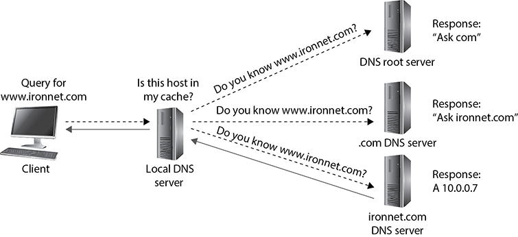
Figure 13-6 A recursive DNS query
Preventing Common DNS Attacks
DNS is the Internet’s ubiquitous messenger; its queries and responses go everywhere, and without them the Internet as we know it would not work. Because of its importance to most other network systems, DNS traffic is seldom blocked by firewalls or routers. Attackers quickly figured out that this ubiquity makes DNS a preferred tool to manipulate and use for their own nefarious purposes. Perhaps the cleverest application of DNS for unintended purposes is its use to reach out and touch hosts in ways that are difficult to block using pseudo-randomly generated domain names.
EXAM TIP
You will not be tested on the material that covers the following DNS attacks, but note that these attacks are both important to know and illustrative of the challenges we face in securing networks. If you are preparing for the exam only, feel free to move to the “Domain Name System Security Extensions” section.
Domain Generation Algorithms
Once malware is implanted on target systems, the adversaries still need to communicate with those hosts. Since inbound connection attempts would easily be blocked at the firewall, most malware initiates outbound connections to the attacker’s command and control (C2) infrastructure instead. The problem for the attackers is that if they provide a hostname or IP address in the malware, defenders will eventually find it, share it as an indicator of compromise (IOC), and reduce or negate the effectiveness of the C2 system.
To bypass signature detection by intrusion detection systems (IDSs) and intrusion prevention systems (IPSs) that use these IOCs, malware authors developed algorithms that can generate different domain names in a manner that appears random but produces a predictable sequence of domain names for those who know the algorithm. Suppose I am an attacker and want to hide my real C2 domains to keep them from being blocked or removed. I develop a domain generation algorithm (DGA) that produces a new (seemingly) random domain name each time it is run. Sprinkled somewhere in that (very long) list of domains are the ones I actually want to use. The infected host then attempts to resolve each domain to its corresponding IP address using DNS. Most of the domains do not exist and others may be benign, so either way there is no malicious C2 communications that follow. However, since I know the sequence of domains generated by the DGA and I know how quickly the malware will generate them, I can determine approximately when a particular infected host will query a specific domain. I can then register it the day before and rendezvous with the malware on that domain so I can receive its report and/or issue commands. The defenders won’t know which domains are my malicious ones and which are just noise meant to distract them.
Figure 13-7 shows three domains being generated by an infected host. The first two that are queried do not exist, and thus result in an NXDOMAIN response from the server, which means the domain was not found. The third domain resolves to a malicious domain. When the authoritative (malicious) server for that domain receives the request, it knows it comes from a compromised system and sends a response that, when decoded, means “sleep for 7 hours.”
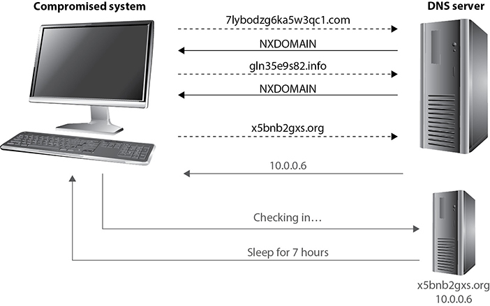
Figure 13-7 DGA in use by a compromised system
How can we detect and stop this kind of adversarial behavior? There are two general approaches. The first is to capture the malware and reverse engineer its DGA. We then play it forward (just like the attacker does) to determine which domains will be generated and when. Knowing this timeline, you can blacklist the domains and use the fact that a host attempted to reach them to infer that the querying system is compromised. Keep in mind that different compromised systems will be generating domain names at different times, so the task is onerous even for organizations that are mature enough to reverse engineer malware in the first place.
The second approach to detecting and stopping the use of DGAs is to analyze the domain names in each query to determine the probability of the query being legitimate. You can see from Figure 13-7 that most domains generated by these algorithms look, well, random. They are not the sort of domain names that you would expect someone to pay money to register. If you find a domain that is highly suspicious, you can investigate the host to see if it is infected, or you could block or monitor the DNS query and response to see if there is anything suspicious in either. For example, in some cases, the response will come as an encoded or encrypted message in a TXT record. This approach is only practical if you have a fairly sophisticated artificial intelligence analysis system that can examine every DNS request and learn over time which ones are likely to be bad.
NOTE
There are legitimate uses of DGAs. For example, some systems use them to test whether or not a system can reach the Internet and perhaps track who that system is. This is done by some developers for licensing, updating, or diagnostic purposes.
DNS Tunneling Malicious use of a DGA can be very hard to stop unless you have advanced capabilities at your disposal. Fortunately, however, this use is limited to simple messaging between a compromised host and an external threat actor. But what if we could use DNS to transfer more information? A lot more? It turns out that data can be hidden in DNS queries using encoded host and other resource labels. DNS tunneling is the practice of encoding messages in one or a series of DNS queries or responses for exfiltrating or infiltrating data into an environment.
Figure 13-8 shows a very simple example of DNS tunneling that builds on our discussion of recursive queries in Figure 13-6. In this case, the compromised system wants to check in with its C2 server, so it uses Base64 encoding to obfuscate its message, which contains its identifier. Let’s say that this is an infected host in the Acme Corporation, so its ID is 1234@acme. The recursive DNS query eventually is sent to the server that owns the malicious domain g00dsite.com. It decodes the hostname field, sees which of its bots this is from, and decides it is time to wipe the file system on the infected system. This command comes in the form of a TXT response that is also Base64 encoded.

Figure 13-8 Covert communication over a DNS tunnel
A similar, but much less noticeable, use of DNS tunneling is to slowly exfiltrate data from the compromised system. Since DNS allows names of up to 63 characters between each dot, attackers can break down a longer file (e.g., a secret document) and exfiltrate it in a sequence of DNS queries to the same server or different servers.
Defending against DNS tunneling is similarly difficult to countering DGAs. Again, we could use network detection and response (NDR) solutions that use artificial intelligence to look for this type of behavior. However, because this type of attack (unlike DGAs) tends to rely on just a few domains, we could use domain reputation tools to determine whether any of our systems are making queries for suspicious or malicious domains.
Distributed Denial of Service
The third type of DNS attack targets someone else’s infrastructure using your DNS servers. An attacker who owns (or can rent) a large army of compromised systems (bots) can use them to overwhelm a target with name resolution responses to queries it didn’t send out in the first place. To see how this attack works, we must first consider that DNS is based on UDP, which means spoofing the source address of a query is trivial.
In a DNS reflection attack, the threat actor instructs each bot they control to send a query to one of many open DNS servers around the world, while spoofing the source addresses on those queries. Collectively, the responding servers then bombard the target with traffic. If you have a sufficient number of bots and servers doing this quickly enough, the results could take the target system offline. Even if the target is not a DNS server, it still has to process millions (or more) of UDP packets arriving each second, which can overwhelm the typical server. But what if we could amplify the effects?
A DNS amplification attack is characterized by small queries that result in very much larger responses. A typical query is about 30 bytes and its response is around 45 bytes on average. The following are three techniques that are used to turn this relatively equal ratio of query to response size by a factor of up to 50 times:
• DNS ANY DNS has a (deprecated in 2019, but still used) diagnostic feature that allows a client to request all the information a server has on a given domain name. By sending a query of type ANY, an attacker can cause the server to send all the records in that domain up to the maximum size of a DNS message, which is 512 bytes. Having a 30-byte query produce a 512-byte response is a 17× amplification.
• EDNS(0) There are several situations in which the 512-byte limit on DNS messages over UDP becomes problematic. In particular, it is not possible to implement DNS Security Extensions (DNSSEC) with this constraint. Therefore, the Internet Engineering Task Force (IETF) developed EDNS(0), the Extension Mechanisms for DNS, which allows for up to 4096-byte responses. Properly used by an attacker, this new maximum size represents a 136× amplification given a 30-byte query.
• DNSSEC One of the most practical ways to exploit the maximum size defined in EDNS(0) is, ironically, using DNSSEC. Going back to Figure 13-6, when the local DNS server requests the A record from the authoritative server for that domain (the bottom left one), it also requests the DNSSEC associated with the zone. This is done to ensure the identity of the authoritative server (and hence the response) but results in a significantly larger response (because it includes a digital signature). So, all an attacker needs to do is find open DNS servers that have DNSSEC enabled and direct the bots at them.
Domain Name System Security Extensions
DNSSEC is a set of standards IETF developed to protect DNS from a variety of attacks. Specifically, DNSSEC is focused on ensuring the integrity of DNS records, not their confidentiality or availability. In plain-old DNS, a client makes a recursive query that, eventually, is responded to by some server that claims to be authoritative and provides an IP address. As we discussed in Chapter 11, however, this led to impersonation attacks where unwitting clients were pointed to malicious hosts. In response to this threat, the IETF came up with DNSSEC.
DNSSEC works by grouping records in a DNS zone according to their name and type (e.g., A, NS, MAIL) into Resource Record Sets (RRSets) that are then digitally signed, with the resulting signature going into a resource record signature (RRSig) record. The corresponding public key is published in a DNSKey record. So, when we want to resolve a fully qualified domain name (FQDN) using DNSSEC, we first retrieve the RRSet containing the name, then we request the RRSig for that set, and finally we verify that the record has not been tampered with. While this approach prevents impersonation and cache poisoning attacks, it has, as we just saw, also opened the door to crippling amplification attacks.
DNS over HTTPS
While DNSSEC ensures the integrity of DNS data, it does nothing to protect the confidentiality or privacy of queries. Sure, you can be confident that the IP address you got back was the right one, but what if anyone on the network can now see that you went to a domain called embarrassingmedicalcondition.com? We know from our discussion of TLS 1.3 earlier in this chapter that this URL will not go out in plaintext over HTTPS (which, by the way, it will in TLS 1.2 and earlier), but it will still be visible before the TLS handshake when the DNS query goes out. This is particularly problematic when we are connected to public networks such as the Wi-Fi network at the local coffee shop.
DNS over HTTPS (DoH) is a (yet to be ratified) approach to protecting the privacy and confidentiality of DNS queries by sending them over HTTPS/TCP/IP instead of unsecured UDP/IP. As of this writing, DoH is available on most platforms, though it is an optional feature that has to be configured. Keep in mind, however, that DoH provides confidentiality but (unlike DNSSEC) not integrity protections. Also, DoH was conceived as a privacy mechanism when using public networks. If you think back to the DNS-enabled attacks we discussed earlier in this chapter (especially DGA and DNS tunneling), DoH would actually make these much harder to detect unless you have a TLS decryption proxy in place. This is one of the reasons why the U.S. NSA recommended in 2021 that DoH not use external resolvers in enterprise networks.
DNS Filtering
Our final topic on securing DNS is perhaps the most obvious. Instead of allowing any DNS request to go out of our organizational networks, what if we first filtered them to block known malicious (or otherwise disallowed) domains from being resolved in the first place? A DNS filter performs a similar role as a web proxy that blocks content that is inappropriate, except that it works on DNS instead of HTTP traffic. There are many commercial solutions that provide this functionality, but keep in mind they should be deployed as part of a broader, defense-in-depth approach to securing DNS.
Electronic Mail
Let’s now shift our attention to the third major service (along with web and DNS services) that is required for virtually all major organizations: e-mail. Though it has lost some ground to other business communication platforms such as Slack, Microsoft Teams, and Google Hangouts, e-mail remains a critical service in virtually all organizations. An e-mail message, however, is of no use unless it can actually be sent somewhere. This is where Simple Mail Transfer Protocol (SMTP) comes in. In e-mail clients, SMTP works as a message transfer agent, as shown in Figure 13-9, and moves the message from the user’s computer to the mail server when the user clicks the Send button. SMTP also functions as a message transfer protocol between e-mail servers. Lastly, SMTP is a message-exchange addressing standard, and most people are used to seeing its familiar addressing scheme: [email protected].
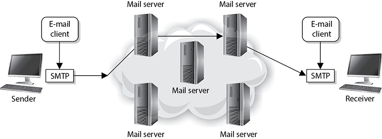
Figure 13-9 SMTP works as a transfer agent for e-mail messages.
Many times, a message needs to travel throughout the Internet and through different mail servers before it arrives at its destination mail server. SMTP is the protocol that carries this message, and it works on top of TCP because it is a reliable protocol and provides sequencing and acknowledgments to ensure the e-mail message arrived successfully at its destination.
The user’s e-mail client must be SMTP-compliant to be properly configured to use this protocol. The e-mail client provides an interface to the user so the user can create and modify messages as needed, and then the client passes the message off to the SMTP application layer protocol. So, to use the analogy of sending a letter via the post office, the e-mail client is the typewriter that a person uses to write the message, SMTP is the mail courier who picks up the mail and delivers it to the post office, and the post office is the mail server. The mail server has the responsibility of understanding where the message is heading and properly routing the message to that destination.
It is worth noting that basic SMTP doesn’t include any security controls. This is why the IETF published Extended SMTP (ESMTP), which, among other features, allows servers to negotiate a TLS session in which to exchange the messages. This implementation, referred to as SMTP Secure (SMTPS), can provide authentication, confidentiality, and integrity protections for mail transfers.
The mail server is often referred to as an SMTP server. The most common SMTP server software in the world is Exim, which is an open-source mail transfer agent (MTA). SMTP works closely with two mail server protocols, POP and IMAP, which are explained in the following sections.
POP
Post Office Protocol (POP) is an Internet mail server protocol that supports incoming and outgoing messages. The current version is 3, so you’ll also see it referred to as POP3. A mail server that uses POP, apart from storing and forwarding e-mail messages, works with SMTP to move messages between mail servers. By default, POP servers listen on TCP port 110.
A smaller organization may have only one POP server that holds all employee mailboxes, whereas larger organizations could have several POP servers, one for each department within the organization. There are also Internet POP servers that enable people all over the world to exchange messages. This system is useful because the messages are held on the mail server until users are ready to download their messages, instead of trying to push messages right to a person’s computer, which may be down or offline.
The e-mail server can implement different authentication schemes to ensure an individual is authorized to access a particular mailbox, but this is usually handled through usernames and passwords. Connections to these clients can be encrypted using TLS by using the secure version of POP, known as POP3S, which typically listens on port 995.
IMAP
Internet Message Access Protocol (IMAP) is also an Internet protocol that enables users to access mail on a mail server (the default TCP port is 143). IMAP provides all the functionalities of POP, but has more capabilities. If a user is using POP, when he accesses his mail server to see if he has received any new messages, all messages are automatically downloaded to his computer. Once the messages are downloaded from the POP server, they are usually deleted from that server, depending upon the configuration. POP can cause frustration for mobile users because the messages are automatically pushed down to their computer or device and they may not have the necessary space to hold all the messages. This is especially true for mobile devices that can be used to access e-mail servers. This is also inconvenient for people checking their mail on other people’s computers. If Christina checks her e-mail on Jessica’s computer, all of Christina’s new mail could be downloaded to Jessica’s computer.
If a user uses IMAP instead of POP, she can download all the messages or leave them on the mail server within her remote message folder, referred to as a mailbox. The user can also manipulate the messages within this mailbox on the mail server as if the messages resided on her local computer. She can create or delete messages, search for specific messages, and set and clear flags. This gives the user much more freedom and keeps the messages in a central repository until the user specifically chooses to download all messages from the mail server.
IMAP is a store-and-forward mail server protocol that is considered POP’s successor. IMAP also gives administrators more capabilities when it comes to administering and maintaining the users’ messages. Just like SMTP and POP, IMAP can run over TLS, in which case the server listens for connections on TCP port 993.
E-mail Authorization
POP has the capability to integrate Simple Authentication and Security Layer (SASL), a protocol-independent framework for performing authentication. This means that any protocol that knows how to interact with SASL can use its various authentication mechanisms without having to actually embed the authentication mechanisms within its code.
To use SASL, a protocol includes a command for identifying and authenticating a user to an authentication server and for optionally negotiating protection of subsequent protocol interactions. If its use is negotiated, a security layer is inserted between the protocol and the connection. The data security layer can provide data integrity, data confidentiality, and other services. SASL’s design is intended to allow new protocols to reuse existing mechanisms without requiring redesign of the mechanisms and allows existing protocols to make use of new mechanisms without redesign of protocols.
The use of SASL is not unique just to POP; other protocols, such as IMAP, Internet Relay Chat (IRC), Lightweight Directory Access Protocol (LDAP), and SMTP, can also use SASL and its functionality.
Sender Policy Framework
A common way to deal with the problem of forged e-mail messages is by using Sender Policy Framework (SPF), which is an e-mail validation system designed to prevent e-mail spam by detecting e-mail spoofing by verifying the sender’s IP address. SPF allows administrators to specify which hosts are allowed to send e-mail from a given domain by creating a specific SPF record in DNS. Mail exchanges use DNS to check that mail from a given domain is being sent by a host sanctioned by that domain’s administrators.
DomainKeys Identified Mail
We can also leverage public key infrastructure (PKI) to validate the origin and integrity of each message. The DomainKeys Identified Mail (DKIM) standard, codified in RFC 6376, allows e-mail servers to digitally sign messages to provide a measure of confidence for the receiving server that the message is from the domain it claims to be from. These digital signatures are normally invisible to the user and are just used by the servers sending and receiving the messages. When a DKIM-signed message is received, the server requests the sending domain’s certificate through DNS and verifies the signature. As long as the private key is not compromised, the receiving server is assured that the message came from the domain it claims and that it has not been altered in transit.
Domain-Based Message Authentication
SPF and DKIM were brought together to define the Domain-based Message Authentication, Reporting and Conformance (DMARC) system. DMARC, which today is estimated to protect 80 percent of mailboxes worldwide, defines how domains communicate to the rest of the world whether they are using SPF or DKIM (or both). It also codifies the mechanisms by which receiving servers provide feedback to the senders on the results of their validation of individual messages. Despite significant advances in securing e-mail, phishing e-mail remains one of the most common and effective attack vectors.
Secure/Multipurpose Internet Mail Extensions
Multipurpose Internet Mail Extensions (MIME) is a technical specification indicating how multimedia data and e-mail binary attachments are to be transferred. The Internet has mail standards that dictate how mail is to be formatted, encapsulated, transmitted, and opened. If a message or document contains a binary attachment, MIME dictates how that portion of the message should be handled.
When an attachment contains an audio clip, graphic, or some other type of multimedia component, the e-mail client sends the file with a header that describes the file type. For example, the header might indicate that the MIME type is Image and that the subtype is jpeg. Although this information is in the header, many times, systems also use the file’s extension to identify the MIME type. So, in the preceding example, the file’s name might be stuff.jpeg. The user’s system sees the extension .jpeg, or sees the data in the header field, and looks in its association list to see what program it needs to initialize to open this particular file. If the system has JPEG files associated with the Explorer application, then Explorer opens and presents the image to the user.
Sometimes systems either do not have an association for a specific file type or do not have the helper program necessary to review and use the contents of the file. When a file has an unassociated icon assigned to it, it might require the user to choose the Open With command and choose an application in the list to associate this file with that program. So when the user double-clicks that file, the associated program initializes and presents the file. If the system does not have the necessary program, the website might offer the necessary helper program, like Acrobat or an audio program that plays WAV files.
MIME is a specification that dictates how certain file types should be transmitted and handled. This specification has several types and subtypes, enables different computers to exchange data in varying formats, and provides a standardized way of presenting the data. So if Sean views a funny picture that is in GIF format, he can be sure that when he sends it to Debbie, it will look exactly the same.
Secure MIME (S/MIME) is a standard for encrypting and digitally signing e-mail and for providing secure data transmissions. S/MIME extends the MIME standard by providing support for the encryption of e-mail and attachments. The encryption and hashing algorithms can be specified by the user of the mail application, instead of having it dictated to them. S/MIME follows the Public Key Cryptography Standards (PKCS). It provides confidentiality through encryption algorithms, integrity through hashing algorithms, authentication through the use of X.509 public key certificates, and nonrepudiation through cryptographically signed message digests.
Multilayer Protocols
Not all protocols fit neatly within the layers of the OSI model. This is particularly evident among devices and networks that were never intended to interoperate with the Internet. For this same reason, they tend to lack robust security features aimed at protecting the availability, integrity, and confidentiality of the data they communicate. The problem is that as the Internet of old becomes the Internet of Things (IoT), these previously isolated devices and networks find themselves increasingly connected to a host of threats they were never meant to face.
As security professionals, we need to be aware of these nontraditional protocols and their implications for the security of the networks to which they are connected. In particular, we should be vigilant when it comes to identifying nonobvious cyber-physical systems. In December 2015, attackers were able to cut power to over 80,000 homes in Ukraine apparently by compromising the utilities’ supervisory control and data acquisition (SCADA) systems in what is considered the first known blackout caused by a cyberattack. A few years later, in 2017, attackers were able to exploit a previously unknown vulnerability and reprogram a Schneider Electric safety instrumented system (SIS) at an undisclosed target, causing the facility to shut down. At the heart of most SCADA systems used by power and water utilities is a multilayer protocol known as DNP3.
Distributed Network Protocol 3
The Distributed Network Protocol 3 (DNP3) is a communications protocol designed for use in SCADA systems, particularly those within the power sector. It is not a general-purpose protocol like IP, nor does it incorporate routing functionality. SCADA systems typically have a very flat hierarchical architecture in which sensors and actuators are connected to remote terminal units (RTUs). The RTUs aggregate data from one or more of these devices and relay it to the SCADA master, which includes a human–machine interface (HMI) component. Control instructions and configuration changes are sent from the SCADA master to the RTUs and then on to the sensors and actuators.
At the time DNP3 was designed, there wasn’t a need to route traffic among the components (most of which were connected with point-to-point circuits), so networking was not needed or supported in DNP3. Instead of using the OSI seven-layer model, its developers opted for a simpler three-layer model called the Enhanced Performance Architecture (EPA) that roughly corresponds to layers 2, 4, and 7 of the OSI model. There was no encryption or authentication, since the developers did not think network attacks were feasible on a system consisting of devices connected to each other and to nothing else.
Over time, SCADA systems were connected to other networks and then to the Internet for a variety of very valid business reasons. Unfortunately, security wasn’t considered until much later. Encryption and authentication features were added as an afterthought, though not all implementations have been thus updated. Network segmentation is not always present either, even in some critical installations. Perhaps most concerning is the shortage of effective IPSs and IDSs that understand the interconnections between DNP3 and IP networks and can identify DNP3-based attacks.
Controller Area Network Bus
Another multilayer protocol that had almost no security features until very recently is the one that runs most automobiles worldwide. The Controller Area Network (CAN) bus is a protocol designed to allow microcontrollers and other embedded devices to communicate with each other on a shared bus. Over time, these devices have diversified so that today they can control almost every aspect of a vehicle’s functions, including steering, braking, and throttling. CAN bus was never meant to communicate with anything outside the vehicle except for a mechanic’s maintenance computer, so there never appeared to be a need for security features.
As automobiles started getting connected via Wi-Fi and cellular data networks, their designers didn’t fully consider the new attack vectors this would introduce to an otherwise undefended system. That is, until Charlie Miller and Chris Valasek famously hacked a Jeep in 2015 by connecting to it over a cellular data network and bridging the head unit (which controls the sound system and GPS) to the CAN bus (which controls all the vehicle sensors and actuators) and causing it to run off a road. As automobiles become more autonomous, security of the CAN bus becomes increasingly important.
Modbus
Like CAN bus, the Modbus system was developed to prioritize functionality over security. A communications system created in the late 1970s by Modicon, now Schneider Electric, Modbus enables communications among SCADA devices quickly and easily. Since its inception, Modbus has quickly become the de facto standard for communications between programmable logic controllers (PLCs). But as security was not built in, Modbus offers little protection against attacks. An attacker residing on the network can simply collect traffic using a tool like Wireshark, find a target device, and issue commands directly to the device.
Converged Protocols
Converged protocols are those that started off independent and distinct from one another but over time converged to become one. How is this possible? Think about the phone and data networks. Once upon a time, these were two different entities and each had its own protocols and transmission media. For a while, in the 1990s, data networks sometimes rode over voice networks using data modems. This was less than ideal, which is why we flipped it around and started using data networks as the carrier for voice communications. Over time, the voice protocols converged onto the data protocols, which paved the way for Voice over IP (VoIP).
IP convergence, which addresses a specific type of converged protocols, is the transition of services from disparate transport media and protocols to IP. It is not hard to see that IP has emerged as the dominant standard for networking, so it makes sense that any new protocols would leverage this existing infrastructure rather than create a separate one.
Technically, the term converged implies that the two protocols became one. Oftentimes, however, the term is used to describe cases in which one protocol was originally independent of another but over time started being encapsulated (or tunneled) within that other one.
Encapsulation
We already saw (in Chapter 9) how encapsulation enables the transmission of data down the seven layers of the OSI reference model. We came across encapsulation again earlier in this chapter when we discussed techniques to tunnel (or encapsulate) one protocol’s traffic inside some other protocol. The next two sections describe two more examples. It should be obvious that encapsulation can be helpful in architecting our networks, but it can also have significant security implications.
When we covered DNS tunneling, we saw another, less helpful application of encapsulation. Threat actors develop their own protocols for controlling compromised hosts and they can encapsulate those protocols within legitimate systems. It is important, therefore, to not assume that just because we have a network link that should be transporting data of a certain protocol, it won’t have something else embedded in it. Whether encapsulation is malicious or benign, the point is that we need to be aware of what traffic should be where and have the means to inspect it to ensure we are not surprised.
Fiber Channel over Ethernet
Fibre Channel (FC) (also called Fiber Channel in the United States) was developed by the American National Standards Institute (ANSI) in 1988 as a way to connect supercomputers using optical fibers. FC is now used to connect servers to data storage devices in data centers and other high-performance environments. One of its best features is that it can support speeds of up to 128 Gbps over distances of up to 500 meters. (Distances of up to 50 km are possible at lower data rates.) While the speed and other features of FC are pretty awesome for data centers and storage area network (SAN) applications, the need to maintain both Ethernet and fiber-optic cabling adds costs and complexity to its use in enterprise environments.
Fibre Channel over Ethernet (FCoE) is a protocol encapsulation that allows FC frames to ride over Ethernet networks. Its use allows data centers to be almost exclusively wired using Ethernet cabling. It is important to note, however, that FCoE rides on top of Ethernet and is, therefore, a non-routable protocol. It is only intended for LAN environments where devices are in close proximity to each other and efficiency is essential.
Internet Small Computer Systems Interface
A much different approach to encapsulation is exemplified by the Internet Small Computer Systems Interface (iSCSI), which encapsulates SCSI data in TCP segments. SCSI is a set of technologies that allows peripherals to be connected to computers. The problem with the original SCSI is that it has limited range, which means that connecting a remote peripheral (e.g., camera or storage device) is not normally possible. The solution was to let SCSI ride on TCP segments so that a peripheral device could be literally anywhere in the world and still appear as local to a computer.
Network Segmentation
Once upon a time, networks were flat (i.e., almost everyone within an organization was in the same layer 2 broadcast domain) so that everyone could easily communicate with everyone else inside the “trusted” perimeter. Network defenses were mostly (sometimes solely) outward-facing. This led to the networks that were “crunchy on the outside but soft and chewy on the inside.” Believe it or not, this was the design mantra for many organizations for many years. Eventually, they realized that this design was a really bad idea. For starters, they recognized that at least some attackers will get through their perimeter defenses. Also, they learned that insider threats could be just as dangerous as external ones, and these insiders would have no problem moving through the soft and chewy interior network. Furthermore, they realized that most networks no longer have a neat concept of “inside” and “outside.” Instead, organizations increasingly rely on external systems such as those provided by cloud service providers.
Network segmentation is the practice of dividing networks into smaller subnetworks. An example is to divide the network by department, so that the finance department and marketing department are each in their own LAN. If they need to communicate directly, they have to go through a gateway (e.g., a router or firewall) that allows network administrators to block or detect suspicious traffic. This is a classic implementation of the zero trust security design principle.
The decision to segment a network begs a couple of questions. How many subnetworks should we have? Are more subnets better? There really is no one-size-fits-all answer, but generally, the smaller the subnetworks (and the more you have), the better. In fact, many organizations are implementing micro-segmentation, which is the practice of isolating individual assets (e.g., data servers) in their own protected network environment. Think of it as a subnet where the only devices are the protected asset and a security gateway.
So, how do we go about segmenting networks? We can do it either physically (using devices like switches and routers) or logically (using virtualization software). We’ll cover devices in detail in the next chapter, so let’s turn our attention to the most important technologies that enable segmentation and micro-segmentation.
VLANs
One of the most commonly used technologies used to segment LANs is the virtual local area network (VLAN). A LAN can be defined as a set of devices on the same layer 2 (data link layer) broadcast domain. This typically means hosts that are physically connected to the same layer 2 switches. A VLAN is a set of devices that behave as though they were all directly connected to the same switch, when in fact they aren’t. This allows you to, for instance, ensure that all members of the finance team are on the same (virtual) LAN, even though they are scattered across multiple countries. The ability to segment networks of users in this manner is critical for both functional and security reasons.
Virtually all modern enterprise-grade switches have the capability to use VLANs. VLANs enable administrators to separate and group computers logically based on resource requirements, security, or business needs instead of the standard physical location of the systems. When repeaters, bridges, and routers are used, systems and resources are grouped in a manner dictated by their physical location. Figure 13-10 shows how computers that are physically located next to each other can be grouped logically into different VLANs. Administrators can form these groups based on the users’ and organization’s needs instead of the physical location of systems and resources.
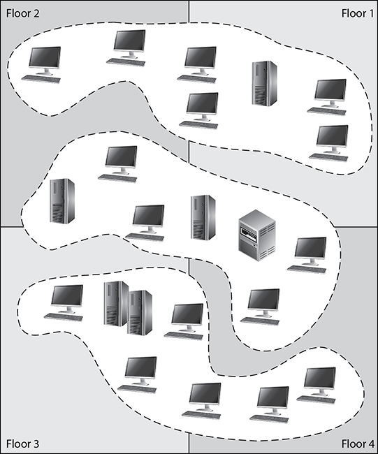
Figure 13-10 VLANs enable administrators to manage logical networks.
An administrator may want to segment the computers of all users in the marketing department in the same VLAN network, for example, so all users receive the same broadcast messages and can access the same types of resources. This arrangement could get tricky if a few of the users are located in another building or on another floor, but VLANs provide the administrator with this type of flexibility. VLANs also enable an administrator to apply particular security policies to respective zones or segments. This way, if tighter security is required for the payroll department, for example, the administrator can develop a policy, add all payroll systems to a specific VLAN, and apply the security policy only to the payroll VLAN.
A VLAN exists on top of the physical network, as shown in Figure 13-11. Each Ethernet frame is prepended with a VLAN identifier (VID), which is a 12-bit field. This means that we can define up to 4,095 VLANs in the same network. (The first and last VID values are reserved.) If workstation P1 wants to communicate with workstation D1, the message has to be routed—even though the workstations are physically next to each other—because they are on different logical networks.
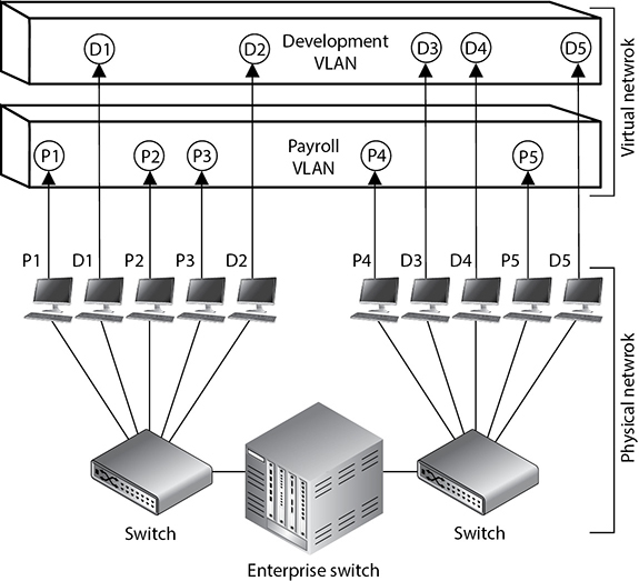
Figure 13-11 VLANs exist on a higher level than the physical network and are not bound to it.
NOTE
The IEEE standard that defines how VLANs are to be constructed and how tagging should take place to allow for interoperability is IEEE 802.1Q.
While VLANs are used to segment traffic, attackers can still gain access to traffic that is supposed to be “walled off” in another VLAN segment. VLAN hopping attacks allow attackers to gain access to traffic in various VLAN segments. An attacker can have a system act as though it is a switch. The system understands the tagging values being used in the network and the trunking protocols and can insert itself between other VLAN devices and gain access to the traffic going back and forth. This is called a switch spoofing attack. An attacker can also insert VLAN tags to manipulate the control of traffic at the data link layer in what is known as a double tagging attack. Proper configuration of all switches mitigates VLAN hopping attacks.
Virtual eXtensible Local Area Network
VLANs, however, have some significant limitations. For starters, remember that you’re limited to around 4,000 VLANs because the VID is 12 bits. While this sounds like a lot, it really isn’t if you happen to be a cloud-based service provider supporting hundreds of customers. Another challenge is that VLANs are layer 2 constructs separated by layer 3 routers. This means that all the hosts on a given VLAN must be on the same port of the same router. In other words, if the hosts are in different countries, it becomes really hard to join them to the same VLAN.
The Virtual eXtensible Local Area Network (VxLAN) is a network virtualization technology that encapsulates layer 2 frames onto UDP (layer 4) datagrams for distribution anywhere in the world. Whereas VLANs have VIDs, VxLANs have a virtual network identifier (VNI) that is 24 bits long, which gives us over 16 million segments. VxLANs are mostly used in cloud environments where hosts and networks are virtualized.
VxLANs are overlay networks on top of UDP/IP underlay networks. Each network switch or router that is part of a VxLAN has a virtual tunnel end point (VTEP) that provides the interface between the underlay and overlay networks. When a VTEP receives a frame, it establishes a virtual tunnel on the overlay network connecting it to the destination VTEP just long enough to deliver the frame. The VTEP encapsulates this overlay frame in UDP datagrams that are then passed to the underlay network for delivery.
Software-Defined Networks
Software-defined networking (SDN) is an approach to networking that relies on distributed software to provide unprecedented agility and efficiency. Using SDN, it becomes much easier to dynamically route traffic to and from newly provisioned services and platforms. This means a new server can be quickly provisioned using a cloud service provider in response to a spike in service requests and the underlying network can just as quickly adapt to the new traffic patterns. It also means that a service or platform can be quickly moved from one location to another and the SDN will just as quickly update traffic-flow rules in response to this change. Unsurprisingly, the three biggest drivers to the adoption of SDN are the growth in cloud computing, big data, and mobile computing.
How does SDN differ from traditional networking? Whereas traditional networking relies on network devices that coordinate with one another in a mostly decentralized manner, SDN centralizes the configuration and control of devices. In a decentralized environment, it takes time for routers to converge onto (or agree on) good routes. These devices must normally be manually configured whenever any changes take place, which is also a time-consuming task. In SDN, on the other hand, all changes are pushed out to the devices either reactively (i.e., in response to requests from the devices) or proactively (i.e., because the admins know a change is being made, such as the addition of 100 servers). Because it is centrally controlled, the SDN approach allows traffic to be routed much more efficiently and securely. Perhaps the most important element of SDN is the abstraction of control and forwarding planes.
Control and Forwarding Planes
The control plane is where the internetwork routing decisions are being made. Think of this as the part of your router that runs the routing protocol, such as Open Shortest Path First (OSPF). (The analogy is not perfect, but it is useful for now.) The control plane is responsible for discovering the topology of neighboring networks and maintaining a table of routes for outbound packets. Since most networks are pretty dynamic places in which congestion along different routes is always changing, the control plane is a pretty dynamic place as well. New routes are routinely being discovered, just as old routes are dropped or at least flagged as slow or expensive. As you can see, the control plane is mostly interested in effects that are more than one hop away.
The forwarding plane, by contrast, is where traffic forwarding decisions are made. Think of this as that part of your router that decides (very quickly) that a packet received on network interface eth0 needs to be forwarded to network interface eth3. How does the forwarding plane decide this? By using the products developed by the control plane. The control plane is the strategic, methodical planner of traffic routing, while the forwarding plane is the tactical, fast executioner of those plans. Unsurprisingly, the forwarding plane is typically implemented in hardware such as an application-specific integrated chip (ASIC).
NOTE
Because traditional routing decisions are made by the controller in an SDN architecture, the network devices behave (and are referred to) as switches.
In a traditional network architecture, each networking device has its own control plane and its own forwarding plane, both of which run on some sort of proprietary operating system (e.g., Cisco IOS). The normal way of reconfiguring these traditional devices is via a terminal connection of some sort. This means that an administrator must remotely log into each device in order to change its configuration. Let’s suppose that we want to support a distinct QoS for a new user. In order to do this, we’d modify the configuration in each networking device that would be involved in providing services to this user. Even assuming that we are able to do this without making any mistakes, we still face the onerous task of manually changing these parameters whenever the terms of the contract change, or when equipment is replaced or upgraded, or when the network architecture changes. There are exceptions to these challenges, of course, but the point is that making frequent, granular configuration changes is tough.
In SDN, by contrast, the control plane is implemented in a central node that is responsible for managing all the devices in the network. For redundancy and efficiency, this node can actually be a federation of nodes that coordinate their activities with one another. The network devices are then left to do what they do best: forward packets very efficiently. So the forwarding plane lives in the network devices and the control plane lives in a centralized SDN controller. This allows us to abstract the network devices (heterogeneous or otherwise) from the applications that rely on them to communicate in much the same way Windows abstracts the hardware details from the applications running on a workstation.
Approaches to SDN
The concept of network abstraction is central to all implementations of SDN. The manner in which this abstraction is implemented, however, varies significantly among flavors of SDN. There are at least three common approaches to SDN, each championed by a different community and delivered primarily through a specific technology:
• Open The SDN approach championed by the Open Networking Foundation (ONF) (https://opennetworking.org) is, by most accounts, the most common. It relies on open-source code and standards to develop the building blocks of an SDN solution. The controller communicates with the switches using OpenFlow, a standardized, open-source communications interface between controllers and network devices in an SDN architecture. OpenFlow allows the devices implementing the forwarding plane to provide information (such as utilization data) to the controller, while allowing the controller to update the flow tables (akin to traditional routing tables) on the devices. Applications communicate with the controller using the RESTful or Java APIs.
• API Another approach to SDN, and one that is championed by Cisco, is built on the premise that OpenFlow is not sufficient to fully leverage the promise of SDN in the enterprise. In addition to OpenFlow, this approach leverages a rich API on proprietary switches that allows greater control over traffic in an SDN. Among the perceived shortcomings that are corrected are the inability of OpenFlow to do deep packet inspection and manipulation and its reliance on a centralized control plane. This proprietary API approach to SDN is seen as enriching rather than replacing ONF’s SDN approach.
• Overlays Finally, one can imagine a virtualized network architecture as an overlay on a traditional one. In this approach, we virtualize all network nodes, including switches, routers, and servers, and treat them independently of the physical networks upon which this virtualized infrastructure exists. The SDN exists simply as a virtual overlay on top of a physical (underlay) network.
Software-Defined Wide Area Network
Software-defined wide area networking (SD-WAN) is the use of software (instead of hardware) to control the connectivity, management, and services between distant sites. Think of it as SDN applied to WANs instead of LANs. Similarly to SDN, SD-WAN separates the control plane from the forwarding plane. This means that network links, whether they are leased lines or 5G wireless, are better utilized. Also, since the control plane is centralized, security policies can be consistently applied throughout.
Another advantage of SD-WANs is that they are application-aware, meaning they know the difference between supporting video conferencing (low latency, loss tolerance), supporting file transfers (latency tolerance, loss intolerant), or supporting any other sort of traffic. This means SD-WANs use the right path for the traffic and are able to switch things around as links become congested or degraded.
Chapter Review
Securing our networks is a lot more effective if we first understand the underlying technologies and then apply secure design principles to their selection and integration. This chapter built on the foundations of the previous two chapters to show common approaches to building and operating secure networking architectures. We focused our attention on network encryption and service security techniques but also covered how to deal with dispersed networks and those with cloud service components. A key aspect of our discussion was the application of the secure design principles at multiple points. We’ll continue this theme in the next chapter as we talk about securing the components of our networks.
Quick Review
• Link encryption encrypts all the data along a specific communication path.
• End-to-end encryption (E2EE) occurs at the session layer (or higher) and does not encrypt routing information, enabling attackers to learn more about a captured packet and where it is headed.
• Transport Layer Security (TLS) is an E2EE protocol that provides confidentiality and data integrity for network communications.
• Secure Sockets Layer (SSL) is the predecessor of TLS and is deprecated and considered insecure.
• A virtual private network (VPN) is a secure, private connection through an untrusted network.
• The Point-to-Point Tunneling Protocol (PPTP) is an obsolete and insecure means of providing VPNs.
• The Layer 2 Tunneling Protocol (L2TP) tunnels PPP traffic over various network types (IP, ATM, X.25, etc.) but does not encrypt the user traffic.
• Internet Protocol Security (IPSec) is a suite of protocols that provides authentication, integrity, and confidentiality protections to data at the network layer.
• TLS can be used to provide VPN connectivity at layer 5 in the OSI model.
• A web service is client/server system in which clients and servers communicate using HTTP over a network such as the Internet.
• A service-oriented architecture (SOA) describes a system as a set of interconnected but self-contained components that communicate with each other and with their clients through standardized protocols.
• Application programming interfaces (APIs) establish a “language” that enables a system component to make a request from another component and then interpret that second component’s response.
• The Hypertext Transfer Protocol (HTTP) is a TCP/IP-based communications protocol used for transferring data between a server and a client in a connectionless and stateless manner.
• A uniform resource identifier (URI) uniquely identifies a resource on the Internet.
• HTTP Secure (HTTPS) is HTTP running over TLS.
• The Simple Object Access Protocol (SOAP) is a messaging protocol that uses XML over HTTP to enable clients to invoke processes on a remote host in a platform-agnostic way.
• SOAP security is enabled by a set of protocol extensions called the Web Services Security (WS-Security or WSS) specification, which provides message confidentiality, integrity, and authentication.
• Representational State Transfer (REST) is an architectural pattern used to develop web services without using SOAP.
• A domain generation algorithm (DGA) produces seemingly random domain names in a way that is predictable by anyone who knows the algorithm.
• DNS tunneling is the practice of encoding messages in one or a series of DNS queries or responses for exfiltrating or infiltrating data into an environment.
• DNS reflection attacks involve sending a query to a server while spoofing the source address to be that of the intended target.
• A DNS amplification attack is characterized by small queries that result in very much larger responses.
• Domain Name System Security Extensions (DNSSEC) is a set of IETF standards that ensures the integrity of DNS records but not their confidentiality or availability.
• DNS over HTTPS (DoH) is a (yet to be ratified) approach to protecting the privacy and confidentiality of DNS queries by sending them over HTTPS/TCP/IP instead of unsecured UDP/IP.
• E-mail spoofing is a technique used by malicious users to forge an e-mail to make it appear to be from a legitimate source.
• Simple Authentication and Security Layer (SASL) is a protocol-independent framework for performing authentication that is typically used in POP3 e-mail systems.
• The Sender Policy Framework (SPF) is an e-mail validation system designed to prevent e-mail spam by detecting e-mail spoofing by verifying the sender’s IP address.
• The DomainKeys Identified Mail (DKIM) standard allows e-mail servers to digitally sign messages to provide a measure of confidence for the receiving server that the message is from the domain it claims to be from.
• Domain-based Message Authentication, Reporting and Conformance (DMARC) systems incorporate both SPF and DKIM to protect e-mail.
• Secure MIME (S/MIME) is a standard for encrypting and digitally signing e-mail and for providing secure data transmissions.
• The Distributed Network Protocol 3 (DNP3) is a multilayer communications protocol designed for use in SCADA systems, particularly those within the power sector.
• The Controller Area Network (CAN) bus is a multilayer protocol designed to allow microcontrollers and other embedded devices to communicate with each other on a shared bus.
• Converged protocols are those that started off independent and distinct from one another but over time converged to become one.
• Fibre Channel over Ethernet (FCoE) is a protocol encapsulation that allows Fibre Channel (FC) frames to ride over Ethernet networks.
• The Internet Small Computer Systems Interface (iSCSI) protocol encapsulates SCSI data in TCP segments so that computer peripherals could be located at any physical distance from the computer they support.
• Network segmentation is the practice of dividing networks into smaller subnetworks.
• A virtual LAN (VLAN) is a set of devices that behave as though they were all directly connected to the same switch, when in fact they aren’t.
• Virtual eXtensible LAN (VxLAN) is a network virtualization technology that encapsulates layer 2 frames onto UDP (layer 4) datagrams for distribution anywhere in the world.
• Software-defined networking (SDN) is an approach to networking that relies on distributed software to separate the control and forwarding planes of a network.
• Software-defined wide area networking (SD-WAN) is the use of software (instead of hardware) to control the connectivity, management, and services between distant sites in a manner that is similar to SDN but applied to WANs.
Questions
Please remember that these questions are formatted and asked in a certain way for a reason. Keep in mind that the CISSP exam is asking questions at a conceptual level. Questions may not always have the perfect answer, and the candidate is advised against always looking for the perfect answer. Instead, the candidate should look for the best answer in the list.
1. Which of the following provides secure end-to-end encryption?
A. Transport Layer Security (TLS)
B. Secure Sockets Layer (SSL)
C. Layer 2 Tunneling Protocol (L2TP)
D. Domain Name System Security Extensions (DNSSEC)
2. Which of the following can take place if an attacker is able to insert tagging values into network- and switch-based protocols with the goal of manipulating traffic at the data link layer?
A. Open relay manipulation
B. VLAN hopping attack
C. Hypervisor denial-of-service attack
D. DNS tunneling
3. Which of the following provides an incorrect definition of the specific component or protocol that makes up IPSec?
A. Authentication Header protocol provides data integrity, data origin authentication, and protection from replay attacks.
B. Encapsulating Security Payload protocol provides confidentiality, data origin authentication, and data integrity.
C. Internet Security Association and Key Management Protocol provides a framework for security association creation and key exchange.
D. Internet Key Exchange provides authenticated keying material for use with encryption algorithms.
4. Alice wants to send a message to Bob, who is several network hops away from her. What is the best approach to protecting the confidentiality of the message?
A. PPTP
B. S/MIME
C. Link encryption
D. SSH
5. Which technology would best provide confidentiality to a RESTful web service?
A. Web Services Security (WS-Security)
B. Transport Layer Security (TLS)
C. HTTP Secure (HTTPS)
D. Simple Object Access Protocol (SOAP)
6. Which of the following protections are provided by Domain Name System Security Extensions (DNSSEC)?
A. Confidentiality and integrity
B. Integrity and availability
C. Integrity and authentication
D. Confidentiality and authentication
7. Which approach provides the best protection against e-mail spoofing?
A. Internet Message Access Protocol (IMAP)
B. Domain-based Message Authentication, Reporting and Conformance (DMARC)
C. Sender Policy Framework (SPF)
D. DomainKeys Identified Mail (DKIM)
8. Which of the following is a multilayer protocol developed for use in supervisory control and data acquisition (SCADA) systems?
A. Controller Area Network (CAN) bus
B. Simple Authentication and Security Layer (SASL)
C. Control Plane Protocol (CPP)
D. Distributed Network Protocol 3 (DNP3)
9. All of the following statements are true of converged protocols except which one?
A. Distributed Network Protocol 3 (DNP3) is a converged protocol.
B. Fibre Channel over Ethernet (FCoE) is a converged protocol.
C. IP convergence addresses a specific type of converged protocols.
D. The term includes certain protocols that are encapsulated within each other.
10. Suppose you work at a large cloud service provider that has thousands of customers around the world. What technology would best support segmentation of your customers’ environments?
A. Virtual local area network (VLAN)
B. Virtual eXtensible Local Area Network (VxLAN)
C. Software-defined wide area networking (SD-WAN)
D. Layer 2 Tunneling Protocol (L2TP)
Answers
1. A. TLS and SSL are the only two answers that provide end-to-end encryption, but SSL is insecure, so it’s not a good answer.
2. B. VLAN hopping attacks allow attackers to gain access to traffic in various VLAN segments. An attacker can have a system act as though it is a switch. The system understands the tagging values being used in the network and the trunking protocols and can insert itself between other VLAN devices and gain access to the traffic going back and forth. Attackers can also insert tagging values to manipulate the control of traffic at this data link layer.
3. D. Authentication Header protocol provides data integrity, data origin authentication, and protection from replay attacks. Encapsulating Security Payload protocol provides confidentiality, data origin authentication, and data integrity. Internet Security Association and Key Management Protocol provides a framework for security association creation and key exchange. Internet Key Exchange provides authenticated keying material for use with ISAKMP.
4. B. Secure Multipurpose Internet Mail Extensions (S/MIME) is a standard for encrypting and digitally signing e-mail and for providing secure data transmissions using public key infrastructure (PKI).
5. C. Either TLS or HTTPS would be a correct answer, but since web services in general and RESTful ones in particular require HTTP, HTTPS is the best choice. Keep in mind that you are likely to come across similar questions where multiple answers are correct but only one is best. SOAP is an alternative way to deliver web services and uses WS-Security for confidentiality.
6. C. Domain Name System Security Extensions (DNSSEC) is a set of IETF standards that ensures the integrity and authenticity of DNS records but not their confidentiality or availability.
7. B. Domain-based Message Authentication, Reporting and Conformance (DMARC) systems incorporate both SPF and DKIM to protect e-mail. IMAP does not have any built-in protections against e-mail spoofing.
8. D. DNP3 is a multilayer communications protocol designed for use in SCADA systems, particularly those within the power sector.
9. A. DNP3 is a multilayer communications protocol that was designed for use in SCADA systems and has not converged with other protocols. All other statements are descriptive of converged protocols.
10. B. Since there are thousands of customers to support, VxLAN is the best choice because it can support over 16 million subnetworks. Traditional VLANs are capped at just over 4,000 subnetworks, which would not be able to provide more than a few segments to each customer.