
CHAPTER 7
DC MACHINES
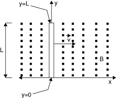
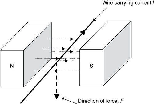
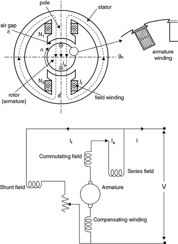
An electric machine is a link between electrical and mechanical systems. The conversion of electrical to mechanical systems is based on transferring voltage and current electrical quantities to mechanical quantities as torque and angular speed and vice versa. Generators and motors can be used interchangeably. Feeding a generator from the mains will convert it to a motor, while driving a motor with a prime mover will convert it to a generator. Generators or motors can be AC or DC machines. DC and AC machines are subject to electromechanical energy conversion, which satisfies Lenz's, Faraday's or Lorentz's fundamental laws. We present herein a simple illustration of two principles on which such machines are developed: The movement of a conductor in a magnetic field gives induced voltage in a conductor in the magnetic field, as shown in Figure 7.1 [1], Figure 7.1 Conductor moving in a magnetic field. where B is the flux density in Tesla or Weber/m2, l is the conductor length (m), and V is the velocity of its movement in the magnetic field (ms−1). When a current-carrying conductor is in a magnetic field of density B Tesla, as shown in Figure 7.2 [1], the conductor experiences a force F given by Figure 7.2 Current-carrying conductor in a magnetic field. A tuning force is impacted on the conductor, causing it to rotate in the magnetic field; this is also due to Lorentz's law. Of all the rotating machines defined so far, synchronous, induction, and DC machines all use these fundamental principles to operate. To generalize these two principles, machines are designed based on two major components, namely a rotating (moving) part called the rotor and a stationary part called the stator. The windings are made of copper, which allows current to flow through or allows for induced voltage based on the two principles. In general, the armature winding used to denote rotor and field winding is also used to denote stator winding for same class of machines. Each of the machines by principle follows the concept—either electric-power conversion to mechanical torque, referred to as motor action, or mechanical-power conversion to electrical power, known as generator action. DC machines are built with salient magnetic poles on the stator and have commutating poles between the main poles. The coils are situated in the interpolar region with contact through carbon brushes. The windings are based on loop configuration and allow for pairs of poles in the wave winding. The brush holder holds the machines against the commutator surface by springs to maintain a constant pressure and smooth running speed. A general schematic of a DC machine is shown in Figure 7.3. It is important to note that compensating winding is in the main poles, whereas the interpole is inserted in the commutating poles, which allows for reversal of current. So, we can claim here that a DC machine can be modeled in three configurations based on the location of the shunt or series winding of the interconnected windings of rotor and stator. Electric motors are described as shunt, series, or compound wound-type configuration depending on exciting current. Figure 7.3 Front elevation and schematic diagram of DC machine. In specifying machines for practical applications, it is important that the parameters are clearly spelled out to ensure easy equipment selection and accurate execution of tasks. Consequently, manufacturers usually include a nameplate on the body of the machine that spells out the machine's important parameters. Important parameters of DC machines that may be found on the nameplate include: From the principles of a rotating conductor, as detailed in Section 7.3, DC-machine armature rotates in a magnetic field produced by the stator magnetic poles. By applying Lenz's law, the voltage induced in the armature winding is given by:
where l is the length of conductor in the slot of the armature, φ is the flux per pole ωm is the mechanical speed, r is the distance of conductor from Consequently, we can recast Equation 7.3 as
This leads to computation of terminal voltage as a function of the number of turns connected in series with the armature, given as
where a is the number of parallel paths and N is the total number of turns in the winding.
Therefore, we observe that Ea is a function of φ and ωm, given So we may now write
where k varies with each machine configuration depending on N, P, π, and a. Assume
then
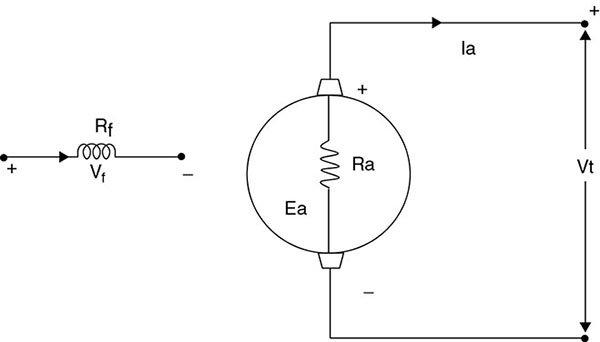
Ea is now fully defined as voltage in generator operation and Ea is given as back emf in motor operation. Typically, we develop the equivalent circuit (Figure 7.4) as follows under steady-state operations. As a generator (DC machine) we write Figure 7.4 DC machine equivalent circuit. and
or simply
Combining these two equations
where ka depends on number of conductor and pole pairs, i.e.,
Based on the second fundamental equation of machine operation (Equation 7.2), torque is developed based on resulting force on the conductor by Lorentz's equation. Torque is produced by armature winding with current in a magnetic-field winding of the stator. The force armature conductor is calculated as
which gives the average torque
where ka is a design constant that depends on Therefore, in the case of motor operation: Simply, in the case of a motor
where Tωm is the developed power within the mechanical system. The converse is also true for a motor or generator operation. So, we can write
where Ka, Wm, φ, and Ia are already defined. Example 1 A shunt generator delivers 450A at 230 V and the resistance of the shunt field and armature are 50 ohm and 0.03 ohm, respectively. Calculate the generated emf. Solution: Current through shunt field winding
Load current
Armature current
Armature voltage drop
Example 2 A four-pole DC machine has an armature of radius 12.5 cm, effective length of 25 cm. The poles cover 75 percent of the armature periphery. The armature windings consist of thirty-three coils each having seven turns. The coils are accommodated in thirty-three slots. The average flux density under each pole is 0.75T. If the armature is wound, determine: If the armature is wave wound, repeat (a)–(d) above. Solution: pole area
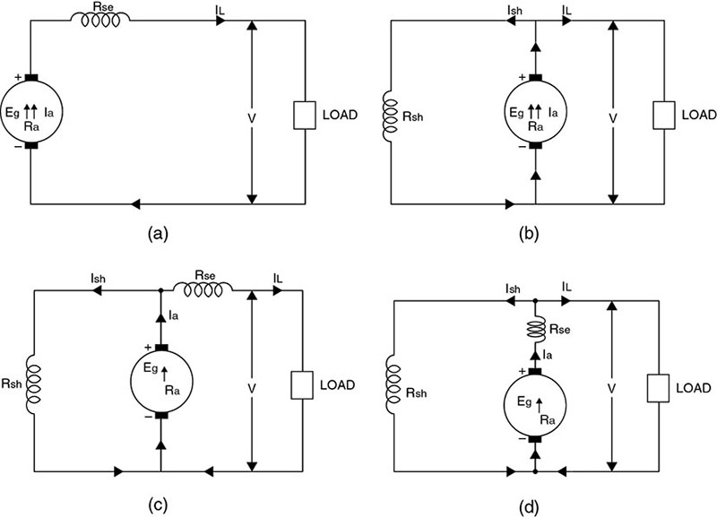
or wave wound The field current and armature current can be interconnected in many ways to provide various performance characteristics for DC-machine configuration. Figure 7.5 DC-machine configurations. (a) Series DC machine (b) Shunt DC machine (c) Compound (short shunt) (d) Compound (long shunt). The compound-machine configuration combines series and shunt winding and these two windings have different performance. The rheostat helps control the field current to achieve the desired performance. Given these configurations, we now develop analysis for DC generators using the circuit equivalent. Consider the machine to be separately excited (Figure 7.6), then the relevant equations are: Figure 7.6 Separately excited DC machine. and
where
These equations define the termed or external Vt of the separately excited DC generator. The relationship between Vt and It for different operating conditions is shown in Figure 7.7 [2]. Figure 7.7 Terminal and load characteristics of separately excited generator. From the terminal characteristics of a separately excited DC generator, there is a voltage drop due to armature reaction (ΔVAR) from the machine internal characteristics to external characteristics. The operating point is the intersection between the generator's external characteristics and the load characteristics. The operating point gives the operating values of load current and terminal voltage. Example 1 A shunt generator delivers 450A at 230 V and the resistance of the shunt field and armature are 50 ohm and 0.03 ohm, respectively. Calculate the generated emf. Solution: Current through shunt field winding = Ish = 230/50 = 4.6A Load current
Armature current
Armature voltage drop
Example 2 A long-shunt compound generator delivers a load current of 50A at 500 V and has armature, series-field, and shunt-field resistances of 0.05 ohm, 0.03 ohm, and 250 ohm, respectively. Calculate the generated voltage and the armature current. Allow 1 V per brush for contact drop. Solution:
Current through armature and series winding = 50 + 2 = 52A Voltage drop on series field winding = 52 × 0.03 = 1.56V Armature voltage drop = IaRa = 52 × 0.05 = 2.6V Drop at brushes = 2 × 1 = 2V Now,
Example 3 A short-shunt compound generator delivers a load current of 30A at 220 V and has armature, series-field, and shunt-field resistance of 0.05 ohm, 0.3 ohm, and 200 ohm, respectively. Calculate the induced emf and armature current. Allow 1.0 V per brush for contact drop. Solution: Example 4 A 12 kW, 100 V, 1,000 rpm DC shunt generator has armature resistance Ra = 0.1 ohm, shunt-field winding resistance Rf = 80 ohm, and Nf = 1, 200 turns/pole. Rated field current is 1A. Find Vt at full load if Ea is 98 V. If armature resistance is at full load of 0.06A, determine full load at Vt. Solution: Given that
Example 5 Determine the field current required to make the terminal voltage of Vt = 100V at full load. Solution:
so
Vt, NL is the no-load terminal voltage, and Since Ea is equal to Vt, NL,
For DC-machine operation, DC current must be provided. Use
at armature reaction
where
Finally, the total resistance
This is used to determine the performance of the machine.
where
Assume a DC machine has Va, Ia, Ea, Kmax, then
This can be written as function of losses
and the corresponding torque
where
so that
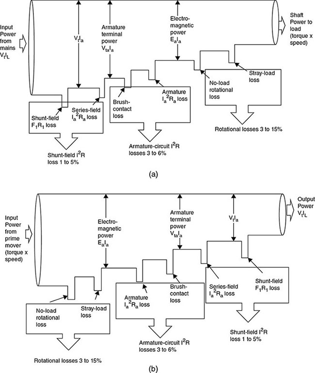
nm is in rad/s. Using the loss formula, we can determine power flow and efficiency of the machine. From the Figure 7.8a and Figure 7.8b, we can compute efficiency Figure 7.8 Losses and energy flow in DC generators and motors. (a) Energyflow in DC motor (b) Energy flow in DC generators.
where
Copper loss depends on armature-winding loss (I2aRa) or field-winding losses (I2fRf) when Ia and If are armature- and field-winding currents, respectively, Ra and Rf are armature and field resistances, respectively, brush loss Pb = VbIa, and Vb is the voltage drop across brushes, which is typically about 2 V. The core loss is derived from the eddy-current and hysteresis losses, as discussed in Chapter 2. Core loss depends on the value of the magnetic flux density B and the speed of rotation of the machine. Mechanical losses can be given as a function of friction and windage. Stray losses account for approximately 1 percent of full-load loss. Power losses in DC machines are given or empirically computed. Example 1 A shunt generator delivers 195A at terminal voltage 250 V. The armature resistance and shunt-field resistance are 0.02Ω and 50Ω, respectively. The iron and frictional losses equal 950 W. Find: Solution: Under a steady-state condition, the interaction between voltage and current for DC machines is given as
where we further suggest, as discussed in Section 7.12, that for a motor
from which it can be further shown that
So, as usual
Different configurations can be represented as follows: From the fundamental expression
which means that speed, ωm, depends on the applied voltage Vt, armature current Ia, armature resistance Ra, and flux φ per pole. The schematic diagram (as seen in Figure 7.9) of each DC-motor configuration with respect to control options is given as follows: Figure 7.9 Configuration types of DC motors. Configuration (a) shunt DC motor (b) Series DC motor (c) Compound motor. For configuration (a), shunt motor
So, we can write
For configuration (b), series DC motor
So, we can write
For configuration (c), compound motor
But
Then,
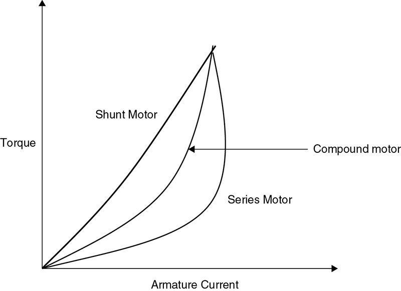
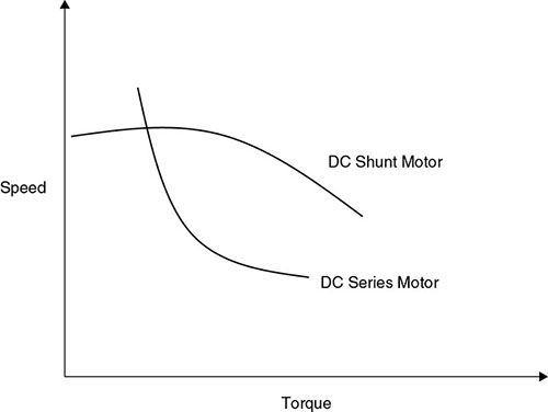
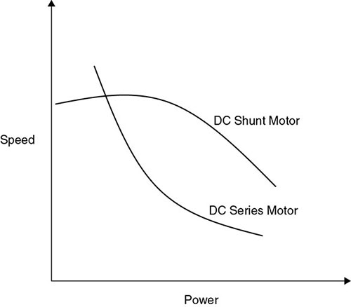
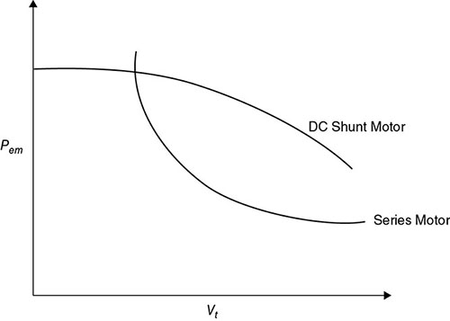
The following figures namely Figures 7.10, 7.11, and 7.12 show the torque/armature current characteristics, torque/speed characteristics and speed/power characteristics respectively of the dc motor. Figure 7.10 Torque/armature-current characteristics. Figure 7.11 Torque/speed characteristics of a DC-motor configuration. Figure 7.12 Speed/power characteristics of a DC-motor configuration. A shunt machine is a constant-speed machine with low-speed regulation. Speed can be controlled by field flux. For a series motor, recall the equation for Te given as
If Ra ≈ 0, Te is a function of flux φ, terminal voltage will be
from which
Also
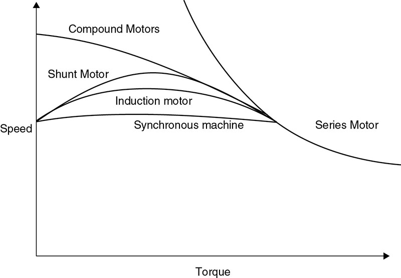
Thus, the speed/power relationship is as shown in Figure 7.13. Figure 7.13 Speed–power relationship. The relationship between speed and torque for each class of DC-machine configuration operating as a motor is as shown in Figure 7.14. Figure 7.14 Speed-torque characteristics of electric machines. Example 1 A 440 V shunt motor has armature resistance of 0.8 ohm and field resistance of 200 ohm. Determine the back emf when giving an output of 7.46 kW at 85 percent efficiency. Solution: Now, Example 2 The following data is for a DC shunt motor:
At no load, armature resistance = 0.5Ω, speed = 1,000 rpm, armature current = 4A, torque = 10Nm. Solution: Assume field current
with machine on load
We can now obtain
Since
we can recompute
with corresponding speed
For 10 Hp at 1,200 rpm,
So, given
or
Example 3 The input to a 230 V DC shunt motor is 11 kW. Calculate: The particulars of the motor are: no-load current is 5A, no-load speed is 1,150 rpm, armature resistance is 0.5 ohm, and shunt-field resistance is 110 ohm. Solution: No-load input = 220 × 5 = 1,100 W
with 11 kW input,
Three methods are used mainly for DC machine control: From
Vt is kept constant so ωm depends on If only. φ decreases while speed increases and since If is directly proportional to φ, it follows that by varying If, the machine's speed can be varied. One way to do this is to insert a variable resistance in the field circuit to control If. This is one of the simplest but most efficient methods of DC-machine speed control. Terminal voltage and field current are maintained consistent at their rated values. Motor speed is easily controlled by varying armature resistance through an external rheostat. This control method is simple and inexpensive but has the disadvantage of low efficiency. Again, ωm changes depend on Vt. It is easy to compute voltage regulation or speed regulation using speed regulation
The method of control here is applicable to shunt-, series-, and compound-motor configurations. Silicon-controlled rectifiers (SCRs) are one of the solid-state devices widely used in the control of DC motors. The SCR is used to rectify the voltage and control the armature current of the DC machine by adjusting the firing angle with the application of the appropriate trigger voltage to the gate of the SCR. The firing angle of the SCR determines the amount of DC current supplied to the motor's armature. Thus, by controlling the armature current, the machine is also controlled. This is consistent with the equation
For a DC-series motor it can be shown that
from which we can see that
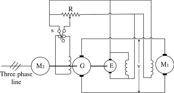
Thus, increasing the armature current results in a decrease in motor speed, which can be achieved using the SCR. For a solid-state control rectifier using a DC machine, the speed-control system is called the Ward Leonard system. It is capable of controlling a DC motor from zero to maximum or maximum to zero. The configuration of the Ward Leonard system is shown in Figure 7.15 [3]. AC source (induction or synchronous machine) serves as the prime mover for a DC generator. The generator in turn supplies Vt, which supplies a DC motor for operation. Figure 7.15 Ward Leonard system control scheme. Varying the field current of the DC machine, which varies the speed of the motor, can consequently control the armature voltage in the motor. That is, the motor speed can be reduced or increased by the motor field current with changes in flux. Further, if the current of the generator is reversed, the polarity of the generator-armature voltage will reverse as well. These reversals also change or cause the motor direction of rotation to change. The speed variation occurs as the field current changes back and forth in the opposite direction for the Ward Leonard system. Solution: The generated emf is given by
For lap wound,
Now,
Solution: For four-parallel path
Solution:
Solution:
We have presented the concepts and fundamental principles of DC machines in this chapter. The internal structures were briefly discussed. Also, the various configurations and their important characteristics were discussed. We distinguished between DC generators and DC motors and discussed methods of speed control. DC motors have found wide applications in control systems. As a rotating machine with an inertial mass, it is of interest to us as it applies to the microgrid. The behavior of DC machines as a generator or motor—for instance on a DC microgrid—should be of practical interest. The student is encouraged to learn these principles as an integral part of the knowledge relative to energy conversion in the smart grid and microgrid. Further, this chapter provided principles for studying the performance of DC-machine applications. A DC series motor operates at 750 rpm with a line current of 80A from the 230 V mains. Its armature circuit resistance is 0.14Ω and its field resistance is 0.11Ω. Assuming that the flux corresponding to a current of 20A is 40 percent of that corresponding to a current of 80A, find the motor speed at a line current of 20A at 230 V. A DC shunt machine is connected across a 500 V supply. The total armature winding resistance is 0.05Ω and the field-circuit resistance is 100Ω. Calculate the ratio of speed as a generator to speed as a motor for the line current to be 200A. A shunt motor draws 26.5A from a 120 V supply when it drives a load at 25 rps. The resistance of the field circuit is 120Ω and the armature-winding resistance is 0.2Ω. What is the electromagnetic torque developed? When a motor is operating under load, the armature takes 8,600 W and its current is 38A. If the armature-circuit resistance, including brushes, is 0.4Ω, what horsepower is developed by the motor? A 240 V, 20HP shunt motor has a resistance of 0.18Ω for the armature circuit, not including brushes (allow for a brush drop of 2 V), and 240Ω for the field circuit. The rated speed is 1,200 rpm and the full-load efficiency is 0.87. Calculate: The resistance of the armature circuit of a 240 V shunt motor is 0.1Ω, including brushes. When the field rheostat is adjusted so that the resistance of the shunt field circuit is 120Ω, the current taken by the motor is 82A and the speed is 900 rpm. Neglecting armature reaction, calculate: A 110 V shunt generator has full-load current of 100A, shunt-field resistance of 55Ω, and constant losses of 500 W. A DC-series motor on full load takes 50A from 230 V DC mains. The total resistance of the motor is 0.22Ω. If the iron and friction losses together amount to 5 percent of the input, calculate the power delivered by the motor shaft. Total voltage drop due to the brush contact is 2 V. A two-pole, DC shunt motor operating from a 200 V supply takes a full-load current of 35A, the no-load current being 2A. The field resistance is 500Ω and the armature has a resistance of 0.6Ω. Calculate the efficiency of the motor on full load. Take the brush drop as being equal to 1.5 V per brush arm.7.1 INTRODUCTION
7.2 CONDUCTOR MOVING IN A UNIFORM MAGNETIC FIELD
![]()
7.3 CURRENT-CARRYING CONDUCTOR IN A UNIFORM MAGNETIC FIELD
7.4 DC-MACHINE CONSTRUCTION AND NAMEPLATE PARAMETERS
7.5 DC MACHINE PERTINENT NAMEPLATE PARAMETERS
7.6 DEVELOPMENT AND CONFIGURATION OF EQUIVALENT CIRCUITS OF DC MACHINES
![]() , and A is the area per pole
, and A is the area per pole ![]() .
.![]()
![]()
![]()
![]()
![]() represented by a constant k for a specific machine.
represented by a constant k for a specific machine.![]()
![]()
![]()
![]()
![]()
![]()
![]()
![]()
![]()
![]()
![]()
![]()
![]() .
.
![]()
![]()
![]()
![]()
![]()


7.7 CLASSIFICATION OF DC MACHINES

![]()
![]()

![]()
![]()

![]()
![]()

![]()
7.8 VOLTAGE REGULATION
![]()
![]() is the full-load terminal voltage.
is the full-load terminal voltage.![]()
7.9 POWER COMPUTATION FOR DC MACHINES
![]()
![]()
![]()
![]()
7.9.1 Loss Calculation
![]()
![]()
![]()
![]()
7.9.2 Torque Computation
![]()
![]()
![]()

![]()
![]()
![]()

7.10 POWER FLOW AND EFFICIENCY
![]()
![]()
![]()
![]()
7.10.1 Core Loss
7.11 DC MOTORS
![]()
![]()
![]()
![]()
![]()
7.12 COMPUTATION OF SPEED OF DC MOTORS
![]()
![]()

![]()
![]()
![]()
![]()
![]()
![]()
![]()
![]()
![]()
![]()

7.12.1 Connection Description
![]()
![]()
![]()
![]()

![]()
![]()

![]()


7.13 DC-MACHINE SPEED-CONTROL METHODS
7.13.1 Field-Control Method
![]()
7.13.2 Armature-Resistance Control Method
![]()
7.13.3 Solid-State Rectifier Control
![]()
![]()
![]()
7.14 WARD LEONARD SYSTEM
Illustrative Problems and Examples
![]()
![]()
![]()

![]()


7.15 CHAPTER SUMMARY
EXERCISES
BIBLIOGRAPHY