
Chapter 3
The Autodesk® Maya® 2016 Interface
This chapter takes you on a guided tour of all the elements visible on the screen for the Autodesk® Maya® 2016 program as you build a simple model of a decorative box. The chapter draws from the experience you had in Chapter 2, “Jumping into Basic Animation Headfirst,” with the solar system exercise. You’ll visit the menus, icons, and shelves to become familiar with the interface basics as you build a model.
This chapter also serves as a good reference when you’re wondering about the purpose of a particular icon.
- Learning Outcomes: In this chapter, you will be able to
- Recognize and use Maya UI elements
- Understand how Maya view panels and windows work
- Use manipulators to transform objects in 3D space
- Create and use reference planes for modeling from pictures
- Use polygon modeling techniques
- Component editing—edges, faces, vertices
- Use the Layer Editor to organize your scene
- Render test frames to preview your work
- Gain confidence in using the Attribute Editor
- Better manage your scenes and object hierarchies with the Outliner
Navigating in Maya
The key to being a good digital artist or animator isn’t knowing where to find all the tools and buttons but knowing how to find the features you need. The purpose of this chapter is to help you get to know Maya and how it operates, building on your experience so far.
Explore the interface. Using your mouse, check out the menus and the tools. Just be careful not to change any settings; the rest of this book and its projects assume your Maya settings are all at their defaults. If you do change some settings inadvertently, reverting to the defaults is easy. Choose Windows ⇒ Settings/Preferences ⇒ Preferences. In the Preferences window, choose Edit ⇒ Restore Default Settings. Now all the settings and interface elements are restored to their default states.
Exploring the Maya Layout
Let’s take another look at the initial Maya screen in Figure 3-1—this time with the Full Perspective window and not the four-panel layout you saw in the previous chapter.

Figure 3-1: The initial Maya screen
The main menu bar, Status line, and Shelf all run across the top of the screen. The Tool Box runs vertically on the left side of the screen. It contains icons for your transform tools (such as Move, Rotate, and Scale) as well as quick-view selections to allow you to customize your panel layouts quickly. The Attribute Editor, Channel Box/Layer Editor, and Modeling Toolkit (the Attribute Editor is currently displayed in Figure 3-1) run down the right side of the screen. Finally, listed from the top down, the Time slider, the Range slider, the Character Set menu, the Auto Keyframe button, and the Animation Preferences button, some of which you’ve already used, run across the bottom of the screen.
The Main Menu Bar
In Maya, menu choices are context sensitive; they depend on what you’re doing. The main menu bar is shown in Figure 3-2. By switching menu sets, you change your menu choices and hence your available tool set. The menu sets in Maya are Modeling, Rigging, Animation, FX, and Rendering.

Figure 3-2: The main menu bar is where the magic happens.
Menu Sets
The Menu Set drop-down is the first thing on the Status line, as shown in Figure 3-3.

Figure 3-3: The Menu Set drop-down menu
No matter which menu set you’re working in, the first seven menu items are constant: File, Edit, Create, Select, Modify, Display, and Windows, as is the last menu entry, Help.
Some plug-ins can also add menu items to the main menu bar. If the plug-in is turned off, that menu item is removed. So, don’t panic if you don’t see the same main menu bar pictured throughout this book.
Submenus and the Option Box

Figure 3-4: Submenus and the all-important option box
You’ll notice two different demarcations to the right of some menu items (Figure 3-4): arrows and boxes (called option boxes). Clicking an arrow opens a submenu that contains more specific commands. Clicking an option box (❏) opens a dialog box in which you can set the options for that particular tool.
Marking Menus
Marking menus are a fast UI workflow to allow you to select commands and options without accessing the main menu bar, as you did in the Hypershade in Chapter 2’s solar system exercise. For example, RMB+clicking any object in your scene gives you the marking menu shown in Figure 3-5. With this particular marking menu, you can select vertices on that object by moving your mouse to the vertex marking box, as shown in Figure 3-6 (top), which takes you to vertex selection mode shown in Figure 3-6 (bottom).

Figure 3-5: A context-sensitive marking menu appears when you RMB+click an object.

Figure 3-6: By using a marking menu, you can easily select components of an object without using the Status line’s icons (top). Vertex selection mode (bottom).
Work Panels and Navigation
The main focus of Maya is its work windows (called viewports or panels), which are the perspective and orthographic views. You use these windows to create, manipulate, and view 3D objects, particles, and animations.
Perspective/Orthographic Panels
The default Maya layout begins with a full-screen perspective view, as shown in Figure 3-7. The top of Figure 3-7 shows the default viewport renderer (called Viewport 2.0), while the bottom of Figure 3-7 shows the old default renderer. Notice you can see the ViewCube, a navigational aid in the upper right of the legacy view mode. You’ll learn more about the ViewCube in a moment, though it is not used very much anymore and therefore removed from Maya 2016’s default view.
By pressing and releasing the spacebar, you can switch your view from the full-screen perspective to the four-panel layout shown in Figure 3-8. Pressing the spacebar again returns your active view panel to full-screen perspective.
Orthographic views (top, front, and side) are most commonly used for modeling because they’re best at conveying exact dimensions and size relationships.
You can also easily change from perspective to any of the orthographic views in the current panel by clicking the ViewCube ( ) in the upper-right corner of any active panel, though by default the ViewCube is not visible. First you must exit Viewport 2.0 as your view panel’s renderer by choosing Renderer in the view panel’s menu bar and then switching to Legacy Default Viewport or Legacy High Quality Viewport, as shown in the bottom image of Figure 3-7. Once you are in a legacy view, you can see the ViewCube. To enable/disable the ViewCube when in the Legacy Viewport renderer, in the main menu bar select Display ⇒ Heads Up Display ⇒ ViewCube.

Figure 3-7: The full perspective view in default panel renderer mode, called Viewport 2.0 (top). The same view is in Maya’s Legacy Default mode (bottom). Notice you can see the ViewCube in the upper-right corner.

Figure 3-8: The four-panel layout
Wireframe and Shaded Modes
When you’re working in the windows, you can view your 3D objects either as wireframe models (as in Figure 3-9) or as solid, hardware-rendered models called Shaded mode (see Figure 3-10). When you press 4 or 5, notice that a text helper opens to tell you your current viewing mode. These messages are called in-view messages and can be helpful as you learn the Maya workflow. You can toggle them on or off by choosing, in the main menu bar, Display ⇒ Heads Up Display ⇒ In-View Messages.

Figure 3-9: Wireframe display of the selected sphere

Figure 3-10: Shaded display of the selected sphere
You can cycle through the modes of display by pressing 4, 5, 6, and 7. Wireframe mode is 4, Shaded mode is 5 and shows you a solid view of the objects, Texture Shaded mode is 6 and shows any textures that are applied to the objects, and Lighted mode is 7 and shows a hardware preview of the objects as they’re lit in the scene. Table 3-1 gives a quick reference for toggling display levels.
Table 3-1: Levels of display detail
| Key | Function |
| 4 | Toggles into Wireframe mode |
| 5 | Toggles into Shaded mode |
| 6 | Toggles into Textured mode |
| 7 | Toggles into Lighted mode |
Pressing 5 for Shaded mode lets you see your objects as solid forms and volumes. Pressing 6 for Texture mode is good for the rudimentary alignment of textures. Pressing 7 for Lighted mode (Figure 3-11) is useful for spotting proper lighting direction and object highlights when you first begin lighting a scene.
Other display commands you’ll find useful while working in the Modeling windows are found under the panel’s (a.k.a. viewport’s) View menu. Look At Selection centers on the selected object or objects. Frame All (hotkey = A) moves the view in or out to display all the objects in the scene, and Frame Selection (hotkey = F) centers on and moves the view in or out to fully frame the selected object or objects in the panel.

Figure 3-11: Lighted mode (press 7) showing a single directional light shining on the sphere
The Manipulators
Manipulators are onscreen handles that you use to manipulate the selected object with tools such as Move or Rotate, as you saw in the solar system exercise. Figure 3-12 shows three distinct and common manipulators for all objects in Maya: Move (press W), Rotate (press E), and Scale (press R). In addition, the fourth manipulator shown in Figure 3-12 is the Universal Manipulator, which allows you to move, rotate, or scale an object all within one manipulator (select Modify ⇒ Transformation Tools ⇒ Universal Manipulator or press Ctrl+T).

Figure 3-12: Using manipulators
You can access the manipulators using either the icons from the Tool Box on the left of the UI or the hotkeys shown in Table 3-2.
Table 3-2: Manipulator hotkeys
| Key | Function |
| W | Activates the Move tool |
| E | Activates the Rotate tool |
| R | Activates the Scale tool |
| Q | Select tool; also deselects any Translation tools |
- Try This In a new scene, choose Create ⇒ NURBS Primitives ⇒ Sphere, drag in a view panel on its grid to create a sphere, and then size it however you like. If you have Interactive Creation already turned off for NURBS primitives, a sphere appears at the origin. Press the 5 key in one of the view panels for Shaded mode. In the previous chapter, you tried the manipulators on a sphere to get a feel for how they work. In Chapter 2 you may have noticed the feedback feature on the Universal Manipulator. Select Modify ⇒ Transformation Tools ⇒ Universal Manipulator, and you’ll notice the Universal Manipulator icon appear just below the Tool Box (
 ). Manipulate the sphere in the view panel and take a look.
The Universal Manipulator interactively shows you the movement, rotation, or scale as you manipulate the sphere. Notice the coordinates that come up and change as you move the sphere. When you rotate using this manipulator, you see the degree of change. Notice the scale values in dark gray on the three outside edges of the manipulator box; they change when you scale the sphere.
Soft Selection
Soft selection is a way to select part of an object (like a vertex) and manipulate it so that neighboring vertices are affected as well, but in decreasing amounts. Soft selection is best described by seeing it in action.
- In a new scene, create a polygonal sphere at the origin.
- RMB+click the sphere to bring up a marking menu. Select vertices as shown in Figure 3-13.
- Your display now shows the sphere as cyan and pink points indicating where the vertices are. (I cover vertices in detail in the next chapter.) Manipulating vertices allows you to alter the shape of the polygonal mesh. As you move your mouse over vertices, they turn into red blocks. Click a single vertex to select it.
- Press W for the Move tool and move the vertex away from the sphere, as shown in Figure 3-14. Doing so creates a spike on the sphere.
- This time, let’s go into the options for the Move tool. Select Modify ⇒ Transformation Tools ⇒ Move Tool ❏ to open the Tool Settings window, shown in Figure 3-15. If you need to expand the window, click and drag the vertical bar on the right of the Tool Settings window to see the full width of the panel.
- Scroll down to the Soft Selection heading and toggle on Soft Select, as shown in Figure 3-16.
- In the persp view panel, RMB+click the sphere again and select Vertex. Select another vertex on the sphere. When you do, a gradient of color from yellow to red to black appears on your model. This gradient shows you the influence of your soft selection. Figure 3-17 shows you the falloff region on the sphere.

Figure 3-13: Selecting vertices

Figure 3-14: Pull a vertex to make a spike.

Figure 3-15: The option box for the Move tool opens Tool Settings.

Figure 3-16: Click Soft Select.

Figure 3-17: Soft Select shows you the falloff gradient.

Figure 3-18: Use soft selection to pull out a bulb rather than a spike.
- The area of influence is too large for this sphere, so set Falloff Radius from 5.0 to 1.0 and move that vertex away from the sphere. This time, instead of a spike forming on the sphere, a much larger, but smooth, bulb forms out of the sphere, as shown in Figure 3-18, much like what would happen if you used the Soft Modification tool.
- You can further adjust the size of the falloff area by adjusting the Falloff Radius attribute in the Tool Settings. Be sure to turn off Soft Select and close the Tool Settings window.
Using soft selection on a transform tool such as Move allows you to make organic changes to your mesh easily.
Symmetry
Using the Symmetry transformation option makes symmetrical edits to a mesh. Follow these steps to experience Symmetry with the Move tool:
- Create a polygonal sphere at the origin in a new scene.
- Invoke the Move tool options by double-clicking the Move tool icon in the Tool Box on the left of the UI, shown in Figure 3-19. The options will open just as if you selected the option box through the menu.

Figure 3-19: Hovering over the icon will give you some information for that tool. Double-clicking the icon will open the options for that tool.
- At the bottom of the Tool Settings window (a.k.a. option box) in the Symmetry Settings section, as shown previously at the bottom of Figure 3-16, click the Symmetry pulldown menu’s down arrow (next to the box that says Off) and select an axis for symmetry. Select Object Z for now.
- Enter component selection mode by RMB+clicking the sphere and choosing Faces from the marking menu that appears.
- Move your cursor over a face, and it turns blue; a face on the opposite side of the sphere turns blue as well. Select a face on one side of the sphere, and a face on the opposite side of the sphere is also selected (Figure 3-20, top). Now when you try to move that selected face, the opposite face moves as well in the opposite direction, as shown in Figure 3-20 (bottom).
- Make sure to turn off Symmetry when you’re done.

Figure 3-20: The user selected the face on the left and moved it. With Symmetry turned on, the opposite face along the Z-axis is also selected and moved.
Building a Decorative Box
Let’s get back to making things and explore the interface as we go along. In this exercise, you’ll build a decorative box, shown in Figure 3-21. You will learn to use reference images for modeling, model polygons with Bevel and Extrude tools, and then add edges with Edge Loop and Multi-Cut. Through the process, the Layer Editor helps you stay organized, and you can hide objects from view. This box will be a fairly simple model to make, but you’ll use it extensively in Chapters 7, 10, and 11 when working with texture, light, and rendering.

Figure 3-21: A photo of the decorative box
Notice that the box has intricately carved grooves and surface features. You’ll build the box to fit the reference and then rely on texture maps created in Chapter 7, “Autodesk® Maya® Shading and Texturing,” to create the details on the surface of the box. You’ll begin by creating reference planes in the next section.
Creating Reference Planes
You can use image references from photos or drawings to model your objects in Maya quite easily. These references are basically photos or drawings of your intended model, usually from three different image views of the model (front, side, and top).
The image reference views of the decorative box have already been created and proportioned properly. (You will see a more thorough review of this process for an exercise in Chapter 6, “Practical Experience.”) You can find the images for the box in the Sourceimages folder of the Decorative_Box project. Table 3-3 lists their names, along with their statistics.
Table 3-3: Reference views and image sizes
| Filename | View | Image size | Aspect ratio |
boxFrontRef.jpg | Front | 1749 x 2023 | 0.865:1 |
boxSideRef.jpg | Side | 1862 x 2046 | 0.910:1 |
boxTopRef.jpg | Top | 1782 x 1791 | 1.005:1 |

Figure 3-22: Make sure Interactive Creation is toggled off.
The idea here is to map these photos to planes created in Maya. First, press Ctrl+A to toggle off the Attribute Editor if it currently appears to the right of the UI. Toggling off the Attribute Editor displays the Channel Box. Next, be sure Interactive Creation is turned off under Create ⇒ Polygon Primitives (Figure 3-22) and then create the reference planes in steps 1 through 3 with the ratios shown in Table 3-4.
- In the front view panel, create a polygonal plane by choosing Create ⇒ Polygon Primitives ⇒ Plane ❏. This plane is for the front image, so in the option box, set Axis to Z, Width to 0.865, and Height to 1.0. Make sure the check box for Preserve Aspect Ratio is deselected, as shown in Figure 3-23. Setting Axis to Z will place the plane properly in the front view. Click Apply to create the plane and keep the option box open.
Table 3-4: Reference planes and sizes
Reference plane Width Height Front 0.865 1 Side 0.910 1 Top 1.005 1 
Figure 3-23: Option box for creating a plane for the front view
- Switch to the side view panel. Create a second plane, this time with a width of 0.910 and height of 1. Set Axis to X and make sure Preserve Aspect Ratio is unchecked. Click Apply to create the plane.
- Switch to the top view panel. Create a third plane with a width of 1.005 and height of 1 and set Axis to Y. Make sure the Preserve Aspect Ratio box is still unchecked and click Create to create the plane and close the option box. Your planes should look like those shown in Figure 3-24.
- Select the front image plane. In the Channel Box, double-click pPlane1 and rename it to frontPlane. Select the side plane and rename it from pPlane2 to sidePlane. Rename the top plane from pPlane3 to topPlane.
- You still need to place and scale these planes to align them. Take a look at Figure 3-25 to size your reference planes and place them as shown. There are two ways to position these planes. You can manually scale and move them to visually match what you see in Figure 3-25, or you can enter the exact values for scale and translation as shown in Table 3-5 using the Channel Box or Attribute Editor (I discuss these windows next before continuing with the box exercise).
Table 3-5: Reference planes: scale and position
| Reference plane | XYZ scale | XYZ position |
| Front | 4.711, 4.711, 4.711 | 0.134, 0.017, –2.167 |
| Side | 4.856, 4.856, 4.856 | –1.979, 0, 0 |
| Top | 4.28, 4.28, 4.28 | 0, 0, 0.133 |
- Save your work using the main menu bar by choosing File ⇒ Save Scene As. Name your work, remembering to use version numbers to keep track of your progress.
You can compare your progress to boxModel01.mb in the Scenes folder of the Decorative_Box project on the book’s web page, www.sybex.com/go/introducingmaya2016.

Figure 3-24: The three view planes are ready and waiting at the origin.

Figure 3-25: Arrange the reference planes for the box model.
The Channel Box/Attribute Editor Explained
To the right of the panels is the Attribute Editor/Channel Box. This is where you’ll find (and edit) most of the information, or attributes, about a selected object. Pressing Ctrl+A toggles between the Attribute Editor and the Channel Box.

Figure 3-26: The Attribute Editor docked to the main UI
The Channel Box lists an object’s channels—that is, the attributes of an object that are most commonly animated. When an object is selected in one of the main views, its name appears at the top of the Channel Box, and its channels are listed. You can edit all the channel values and rename the object itself here.
Toggle on the Attribute Editor by pressing Ctrl+A. This window gives you access to all of a selected object’s attributes, whereas the Channel Box displays only the most commonly animated attributes.
Tabs running across the top of the Attribute Editor give you access to the other nodes related to that object, as shown in Figure 3-26.
You can click and drag the top of the Attribute Editor to undock it from the main UI. Once you have it in its own window, pressing Ctrl+A will open the Attribute Editor in its own window from then on. However, you can dock the Attribute Editor to the main UI by dragging it back over to the Channel Box area. After that, pressing Ctrl+A will toggle between the Channel Box and Attribute Editor again.
Mapping the Box’s Reference Planes with Hypershade
Now you’ll import the three reference JPEG images from the Sourceimages folder into Maya through the Hypershade window. Click Windows ⇒ Rendering Editors ⇒ Hypershade to open this highly powerful texturing window. In the top-left panel (called the Browser), click the Textures tab. This tab will be empty at first, but once you add the reference JPEGs, their icons will show here.
In a file browser (Windows Explorer in Windows or the Finder in Mac OS X) window, navigate to the Sourceimages folder of the Decorative_Box project from the companion web page. One by one, select boxFrontRef.jpg, boxLeftRef.jpg, and boxTopRef.jpg and drag them individually into the bottom panel (called the Work Area) of the Hypershade window, as shown in Figure 3-27.

Figure 3-27: Drag the JPEGs one by one into the Hypershade window’s Work Area.
Once you have imported the JPEG images, the Hypershade displays them in the Work Area. You use the Alt+ LMB, RMB, or MMB key combinations to pan and zoom in the Hypershade window, like in other Maya views.
The Hypershade Browser panel has tabs along the top. Since you already clicked the Textures tab, you will see the three JPEGs there as well. Return to the Materials tab to display your scene’s materials, a.k.a. shaders. There will be three defaults that are always in every Maya scene (lambert1, particleCloud1, and shaderGlow1), which you should leave alone.
The bottom-right panel is the Work Area and is just that: a work area for you to create and edit materials for your scene. The top section (the Browser) displays all the texture and shader nodes available in your scene, again, separated by tabs.
Any time you need to apply a new material to an object in your scene, you need to create a new shader. So for this example, you need to create three new shaders to assign to the reference plane objects. You can load the scene file to boxModel01.mb in the Scenes folder of the Decorative_Box project from the companion web page or continue with your own scene.
- Create three Lambert shaders in the Hypershade by clicking three individual times on the Lambert button in the Create panel on the left side of the Hypershade window, as shown in Figure 3-28. Notice that the new Lambert shaders appear up in the Browser but not in the Work Area (which is disappointing!).
- 2. Simply MMB+click and drag the new Lambert thumbnail icons from the Browser to place them in the Work Area so you can see them all alongside the JPEG nodes of the textures you imported earlier. You can also click and drag the nodes in the Work Area around to arrange them all as shown in Figure 3-29.
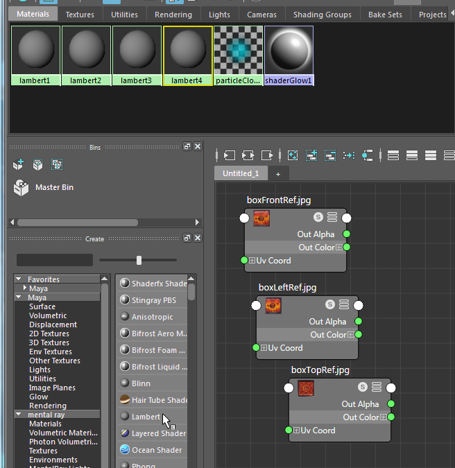
Figure 3-28: Create three new Lambert materials.

Figure 3-29: MMB+click and drag the three new Lambert shaders to the Work Area and arrange the nodes to see everything.
- Select the lambert2 node, and you’ll see some of its attributes in the panel to the right of the Hypershade, called the Property Editor. You will also see a sample render of that shader above the Property Editor in the Material Viewer window, as shown in Figure 3-30.

Figure 3-30: The Property Editor in the Hypershade with the Material Viewer above it displays information about the selected node.
- The nodes you see in the Work Area have colored dots on the left side, called Input Sockets. On the right, the dots are called Output Sockets. These sockets allow you to easily connect textures to shaders. Click the green Output Socket next to Out Color for the boxFrontRef.jpg node, and a rubber band pulls out. Drag the rubber band to the red Input Socket of the lambert2 node, as shown in Figure 3-31. This will make that JPEG image be the color of the lambert2 shader. Rename that Lambert material to topImage.

Figure 3-31: Connect the Out Color socket of the reference image to the Color input of the lambert2 shader.
- Repeat step 4 two times to connect and rename the materials for the front and side views. Make sure you label the materials properly; it’s tough to tell the side and front images apart.
- To assign the materials, simply MMB+drag each shader’s thumbnail icon (or node) from the Hypershade to its respective reference plane in the persp view panel. Press 6 for Texture mode in the Perspective window, as shown in Figure 3-32. Close the Hypershade.
- Choose File ⇒ Save Scene As to save a new version of your work.
You can compare your progress to boxModel02.mb in the Scenes folder of the Decorative_Box project at the companion web page.

Figure 3-32: The images are applied.
The Hypershade Explained
Just as the Outliner window lists the objects in your scene, the Hypershade window lists the textures and shaders. Shaders are assigned to objects to give them their visual appearance—their look and feel.
The Hypershade (Window ⇒ Rendering Editors ⇒ Hypershade) displays shaders and textures in a graphical flowchart layout (see Figure 3-33). The Hypershade window has a few main areas: the Create panel the Bins panel, the Browser panel, the Material viewer, the Property Editor, and the Work Area. The Window menu at the Hypershade’s menu bar allows you to turn on and off any of these panels. You can also tear them off, or dock them into the Hypershade by clicking the top of any panel and dragging it around in the Hypershade.

Figure 3-33: The Hypershade’s default layout
- The Create Panel and Bins Panel Figure 3-33 shows the Create Panel and Bins panel on the left side of the window. The Create panel gives you access to creating a variety of render nodes (shaders and textures, for example) by clicking them. Once you click an icon in the Create panel, it will show up in the Browser panel above. The Bins tab adds a level of organization by letting you store sets of shaders in different bins to sort them. The bar at the top switches between Create Maya Nodes and Create Mental Ray Nodes.
- The Browser panel After you create a render node, it appears in the Browser area as a thumbnail icon. Clicking an icon opens its settings in the Property Editor on the right of the Hypershade window. You use the MMB to drag any icon from the Browser to the Work Area, where you can work on making or editing shading networks.
- The Work Area The Work Area is a free-form workspace where you can connect render nodes to form-shading networks that you can assign to your objects for rendering. You can add nodes to the workspace by MMB+clicking and dragging them from the Browser panel of the Hypershade window.
- The Material Viewer The Material Viewer panel gives you an icon representing how your currently selected material looks. This panel by default sits above the Property Editor. It is usually turned off throughout the figures in this book past this chapter to save space. It is turned on and off through the Window menu in the Hypershade.

Figure 3-34: The Hypershade layout used in this book

Figure 3-35: Turning parts of the Hypershade back on (top) and docking it to the Hypershade (bottom)
- The Property Editor The Property Editor panel gives you access to the settings of any selected node in the Hypershade. This panel has two view options: Lookdev display (shown in Figure 3-33) and Attribute Editor display (as shown in Figure 3-34, where the Material Viewer is also turned off). Lookdev display shows you only the more important settings, a.k.a. properties. The Attribute Editor view shows all the attributes and is almost identical to the main Attribute Editor window in the main Maya UI. You will primarily use the layout shown in Figure 3-34 throughout this book, where the Bins and Material Viewer panels have been turned off to maximize space. You can turn off panels by clicking the Close icon (
 ) in the upper right of any panel.
You can turn any of the panels on and off by accessing the Window menu in the Hypershade, as shown in Figure 3-35, to turn them back on as floating windows. Drag the floating panel to inside the Hypershade to dock it as you prefer.
Organizing Workflow with the Layer Editor

Figure 3-36: The Display tab in the Layer Editor
Now that you have the reference planes set up and mapped, you’ll create display layers to help organize the scene before you actually start modeling. You can load the scene file boxModel02.mb in the Scenes folder of the Decorative_Box project from the companion web page or continue with your own scene.
- Select the three reference planes and toggle off the Attribute Editor to show the Channel Box. Under the Channel Box is the Layer Editor. Click the Display tab, as shown in Figure 3-36.

Figure 3-37: Click to create a new display layer and add the selected objects automatically.
- With the planes selected still, click the Create A New Layer And Assign Selected Objects icon at the top of the Layer Editor, as shown in Figure 3-37. Doing so creates a new layer for these three reference planes.
- In the Layer Editor, double-click the name layer1 to open the Edit Layer window. Rename the layer to referenceLayer, as shown in Figure 3-38.

Figure 3-38: Name the new display layer.
- Toggle the display of this layer by toggling the V icon, shown in Figure 3-39.

Figure 3-39: Toggle the visibility of the reference layer.
- Save another version. You can compare your progress to
boxModel03.mbin the Scenes folder of the Decorative_Box project.
Display layers allow you to easily turn on and off the display of the reference planes as you model the decorative box. Become familiar with this feature early because it will be a valuable asset when you animate complicated scenes.
To add items to an already created layer, select the objects; then RMB+click the desired layer and choose Add Selected Objects. You can also use the layers to select groups of objects by choosing Layers ⇒ Select Objects In Selected Layers or by RMB+clicking the layer and choosing Select Objects. To change the name and color of a layer, double-click the layer to open the Edit Layer window, as shown earlier in Figure 3-38.
Modeling the Decorative Box
Make sure you are in Texture mode (press 6) so you can see the reference plane and the images on them in the persp view panel. Also be sure to toggle on visibility of the references’ display layer. In Chapter 4, I’ll cover in more detail the modeling tools you’ll use.

Figure 3-40: Set the display to X-Ray mode so you can see how the poly cube and the decorative box line up.
You can load the scene file boxModel03.mb in the Scenes folder of the Decorative_Box project from the companion web page or continue with your own scene. To model the box to fit the references, follow these steps:
- With Interactive Creation turned off, select Create ⇒ Polygonal Primitives ⇒ Cube. Position and size the cube to roughly match the size of the reference planes for the decorative box.
- To make it easier to see the reference planes and their images in relation to the box you just created, in the menu bar of the persp view panel, select Shading ⇒ X-Ray, as shown in Figure 3-40. Now you can see the box and the reference images at the same time.
- Scale and position the cube to match the size of the main part of the box, as shown in Figure 3-41. Don’t bother sizing the box to include the little feet on the bottom of the box. Use X-Ray mode in the Side, Front, and Top modeling panels in Maya to line up the cube as best as you can. This will be the base model for the decorative box.
- Switch off X-Ray mode in your views (in the persp view panel’s menu bar, select Shading ⇒ X-Ray). Let’s work on the rounded bevel on top of the box, where the lid is. Select the poly cube, open the Attribute Editor (Ctrl+A), and click the pCubeShape1 tab to access the shape node attributes.

Figure 3-41: Size the cube to fit the box references.
- Under Object Display ⇒ Drawing Overrides, check Enable Overrides to enable it. Deselect Shading to display the poly cube as a wireframe while the reference planes remain displayed as textured planes. This way, you can more easily match the cube to the decorative box (see Figure 3-42).
- RMB+click the box and select Edge from the marking menu, as shown in Figure 3-43.

Figure 3-42: Display the cube as a wireframe.

Figure 3-43: Select Edge from the marking menu.
- Select the top four edges of the cube and switch to the front view, as shown in Figure 3-44. Using the front view, you’ll shape the top of the cube.
- Make sure you are in the Modeling menu set; then select Edit Mesh ⇒ Bevel. Don’t worry about the settings; you’ll adjust them after the fact. You should now have something like Figure 3-45 if your bevel options were at the defaults. Because you created a bevel operation on the cube, Maya has created a new node connected to the cube. You will access this bevel node to adjust the bevel settings on the cube.

Figure 3-44: Select the top four edges.
- RMB+click the cube, select Object Mode from the marking menu, and then select the cube. Toggle on the Attribute Editor and select the new polyBevel1 tab. Using the front view panel, set Fraction so that it lines up with the rounded top of the box, at about 0.26. Set Segments to 12. Make sure Auto Fit, Offset As Fraction, and World Space are all checked (see Figure 3-46).

Figure 3-45: Default bevel

Figure 3-46: Set the bevel to fit the rounded top of the box in the front view panel.
- In the side view panel, move the bottom-corner vertices on the cube to line up the bottom corners of the box to the reference image.
- In the front view panel, move the bottom-corner vertices to match the bottom of the box in the image (see Figure 3-47). Don’t worry about the curvature in the middle of the box or the feet just yet. Save your work.
- Let’s take a quick look at how this box will look rendered now. Click anywhere in the persp view panel to make it the active panel. In the Status line (the group of icons at the top of the screen), click the Render The Current Frame icon, as shown in Figure 3-48.
- Save your work. You can compare your progress to
boxModel04.mbin the Scenes folder of the Decorative_Box project from the companion web page.
When you rendered your work in step 12, the Render View opened to show you a gray shaded box with the reference planes barely showing, as you can see in Figure 3-49.

Figure 3-47: Taper the bottom of the cube.

Figure 3-48: Render a frame of the box from the Status line.

Figure 3-49: The model thus far is rendered.
Status Line Explained
The Status line (see Figure 3-50) contains a number of important and often used icons.

Figure 3-50: The Status line
The Status line begins with a drop-down menu that gives you access to the menu sets in Maya. You’ll notice that intermittently throughout the Status line are white vertical line breaks with either a box or an arrow in the middle. Clicking a break opens or closes sections of the Status line.
Some of the most often used icons are identified here.
Scene File Icons
The tools in the first section of the Status line deal with file operations; they are Start A New Scene (![]() ), Open An Existing Scene (
), Open An Existing Scene (![]() ), or Save Your Current Scene (
), or Save Your Current Scene (![]() ).
).
Selection Modes
Selection modes allow you to select different levels of an object’s hierarchy (see Table 3-6). For example, using a selection mode, you can select an entire group of objects, only one of the objects in that group, or even components (vertices, faces, and so on) on the surface of that object, depending on the selection mode you’re in.
Table 3-6: Selection modes
| Icon | Name | Description |
| Hierarchy and Combinations mode | Lets you select groups of objects | |
| Object mode | Lets you select objects such as geometry, cameras, lights, and so on | |
| Component mode | Lets you select an object’s components, such as vertices, faces, UVs, and so on |
You’ll work with these selection mask filters throughout the book, but you will likely access them through marking menus as you have already done to select vertices and edges of a polygonal object. For a quick preview, hover your cursor over each of the icons to see a tooltip that gives the icon’s name and describes its function.
Snapping Functions, or Snaps
The icons with the magnets are called snaps. They allow you to snap your cursor or object to specific points in the scene, as you saw in the solar system exercise. You can snap to other objects, to CVs or vertices (![]() ), and to grid intersections (
), and to grid intersections (![]() ) and other locations by toggling these icons. Table 3-7 shows the various snaps.
) and other locations by toggling these icons. Table 3-7 shows the various snaps.
The Channel Box/Layer Editor Icons
These last four buttons on the Status line (Figure 3-51) toggle between the Attribute Editor, Channel Box, and Modeling Toolkit view on the right side of the UI. Clicking the first icon (![]() ) shows or toggles the Modeling Toolkit. The second icon (
) shows or toggles the Modeling Toolkit. The second icon (![]() ) toggles the Attribute Editor, much the same as pressing Ctrl+A. The third icon (
) toggles the Attribute Editor, much the same as pressing Ctrl+A. The third icon (![]() ) displays or hides the Tool Settings window along the left side of the UI, as you’ve seen with soft selections. The fourth icon here (
) displays or hides the Tool Settings window along the left side of the UI, as you’ve seen with soft selections. The fourth icon here (![]() ) toggles the display of the Channel Box, again much the same as pressing Ctrl+A.
) toggles the display of the Channel Box, again much the same as pressing Ctrl+A.

Figure 3-51: Attribute Editor/Channel Box/Tool Settings icons
Table 3-7: Snap icons
| Icon | Name | Description |
| Snap To Points | This icon lets you snap objects to object points such as CVs or vertices. | |
| Snap To Grids | This icon lets you snap objects to intersections of the view’s grid. | |
| Snap To Curves | This icon lets you snap objects along a curve. | |
| Snap to Projected Center | This icon lets you snap to the center of a selected object. | |
| Snap To View Planes | This icon lets you snap objects to view planes. | |
| Make The Selected Object Live | This icon has nothing to do with snapping but is grouped with the Snap To icons. It lets you create objects such as curves directly on a surface. |
Editing the Decorative Box Model Using the Shelf
Back to work on the box model. You will use the Shelf in the UI to access some of the commands for the next series of steps as you continue working on the box. The Shelf runs directly under the Status line and contains an assortment of tools and commands in separate tabs, as shown in Figure 3-52.

Figure 3-52: The Shelf
You can load the scene file boxModel04.mb in the Scenes folder of the Decorative_Box project from the companion web page or continue with your own scene.
In the following steps, you have to add surface detail to the model so you can more adequately adjust its shape:
- Orient the persp view panel so you can see the bottom of the box and then select the box model. In the Shelf, click the Polygons tab. Double-click the Multi-Cut tool (as shown in Figure 3-53). The Modeling Toolkit will open on the right showing you the Multi-Cut tool’s settings (Figure 3-54).
- Your cursor will change to a knife icon (it may also give you a cross shape). Click the back edge, as shown in Figure 3-55, and drag along that edge to select a point near the bottom-left edge of the box that corresponds with where the box’s feet begin. The readout should show 75 percent or so.

Figure 3-53: The Multi-Cut Tool icon in the Shelf

Figure 3-54: The Multi-Cut Tool settings

Figure 3-55: Select the first point for the multicut.

Figure 3-56: Create a new edge line along the bottom of the box.
- Click and drag a second point on the opposite edge on the bottom of the box (at about 75 percent again) to create a new edge line, as shown in Figure 3-56. Click the RMB to commit the new edge line. This creates surface detail along the bottom of the box for you to model the feet for the box. This methodology is explained in detail in Chapter 4.
- Using the same procedures in steps 1 through 3, create three more edge lines for a total of four separate cuts in the bottom face of the cube that line up with the legs of the box, as shown in Figure 3-57. The preceding three steps have created a surface detail called faces that allow you to create the feet for the box.

Figure 3-57: Cut the bottom face four times to create divisions for the box’s feet.
- Click the Select Tool icon in the Tool Box to the left of the UI (shown in Figure 3-58) to exit the Multi-Cut tool. Your cursor returns to the regular Maya cursor.

Figure 3-58: The Select tool in the Tool Box
- RMB+click the box and select Face from the marking menu (Figure 3-59). As you hover your mouse over the parts of the box, the new faces in the four corners of the box you just created will highlight in red. Shift+click the four corner faces to select all four faces, as shown in Figure 3-60.

Figure 3-59: Select Face from the marking menu.

Figure 3-60: Select the four corner faces.
- With the four faces selected, go into the Shelf and select the Extrude icon shown in Figure 3-61. This tool is also accessible through the menu Edit Mesh ⇒ Extrude.

Figure 3-61: The Extrude icon in the Shelf
- Your manipulator will change, as shown in Figure 3-62. Grab the Z-axis move handle and drag it down to “pull” the feet out of the bottom of the box as shown.
- By moving vertices, taper the feet to match the reference images in the front and side view panels; see Figure 3-63.
- Save your work. You can compare your progress to
boxModel05.mbin the Scenes folder of the Decorative_Box project.

Figure 3-62: Extrude the feet.

Figure 3-63: Move the vertices on the feet to line them up to the reference images.
The Shelf and Tool Box Explained

Figure 3-64: The Tool Box
Here is a brief explanation of the tools and icons in the Shelf and Tool Box.
The Shelf
The Shelf, shown earlier in Figure 3-52, is an area where you keep icons for tools. It’s divided into tabs that define functions for the tool icons in the Shelf. Don’t worry too much about the Shelf right now; it may be better to use the commands from the menus first before turning to icons and shelves.
The Tool Box
The Tool Box, shown in Figure 3-64, displays the most commonly used tools. Table 3-8 lists the icons and their functions.
In addition to the common commands, the Tool Box displays several choices for screen layouts that let you change the interface with a single click. Experiment with the layouts by clicking any of the six presets in the Tool Box.
Table 3-8: Tool Box icons
| Icon | Name | Description |
| Select | Lets you select objects | |
| Lasso Select | Allows for a free-form selection using a lasso marquee | |
| Paint Selection Tool | Enables the Paint Selection tool | |
| Translate (Move) | Moves the selection | |
| Rotate | Rotates the selection | |
| Scale | Scales the selection | |
| Last Tool Used | Shows the last tool that was used (shown as Insert Edge Loop here, sometimes shown blank) |
Continuing the Decorative Box Model
Back to work! You’ll be spending more time getting the box in shape. You can load the scene file boxModel05.mb in the Scenes folder of the Decorative_Box project or continue with your own scene. In the following steps, you will add more faces and edges to the model surface (a.k.a. mesh) so you can add detail to the shape:
- The middle of the box has a bit of a curve; you will need to create a new edge line that runs across the middle of the box so you can bow out the sides in the middle. In the Layer Editor, toggle off visibility for the reference images by clicking the
 icon for reference planes. Now you can see just the model of the box.
 - Select the box, and in the Polygons tab of the Shelf, double-click the Multi-Cut Tool icon (
 ). Click and drag your Multi-Cut cursor (
 ) along the box’s first edge to place a point in the middle of that edge (at about 50 percent), as shown in Figure 3-65.

Figure 3-65: Insert the first point of a Multi-Cut at about 50 percent along this first edge.
- Place a new split point in the middle of the next edge of the box (working from left to right), creating an edge line along one side of the box. Continue to place two more split points in the middle of each remaining edge to create a horizontal cut line in the middle of the box, as shown in Figure 3-66. Your last point will display the word close next to your cursor. Press Enter, and you now have a horizontal split along the middle of the box.

Figure 3-66: Create a horizontal edge line all the way around the box.
- Click the Select Tool icon in the Tool Box to the left of the UI (
 ) to exit the Multi-Cut tool. Your cursor returns to the regular Maya cursor. Turn on the referencePlanes layer to show the image references.
 - RMB+click the box and choose Vertex from the marking menu. Move the new vertices in the middle of the box to bow out the box slightly. Move the rest of the vertices to match the model to the box images in the side and front view panels (see Figure 3-67).
- Save your work. You can compare your progress to
boxModel06.mbin the Scenes folder of the Decorative_Box project.

Figure 3-67: Adjust the cube to fit the reference images.
Time Slider and Help Line Explained
In this section, you will examine the bottom part of the UI where the Help line and Time slider live.
Time Slider/Range Slider
Running horizontally across the bottom of the screen are the Time slider and the Range slider, as shown in Figure 3-68. The Time slider displays the range of frames available in your animation and gives you a gray bar, known as the Current Time indicator. You can click it and then drag it back and forth in a scrubbing motion to move through time in your sequence. (When instructed in this book to scrub to a certain point in your animation, use this indicator to do so.)

Figure 3-68: The Time and Range sliders
The text box to the right of the Time slider gives you your current frame, but you can also use the text box to enter the frame you want to access. Immediately next to the current time readout is a set of DVD/DVR-type playback controls that you can use to play back your animation.
Below the Time slider is the Range slider, which you use to adjust the range of animation playback for your Time slider. The text boxes on either side of this slider give you readouts for the start and end frames of the scene and of the range selected.
You can adjust any of these settings by typing in these text boxes or by lengthening or shortening the slider with the handles on either end of the bar. When you change the range, you change only the viewable frame range of the scene; you don’t adjust any of the animation. Adjusting the Range Slider lets you zoom into sections of the timeline, which makes adjusting keyframes and timing much easier, especially in long animations.
Command Line/Help Line
Maya Embedded Language (MEL) is the user-accessible programming language of Maya. Use the Command line (see Figure 3-69) to enter single MEL commands directly from the keyboard in the white text box portion of the bar.

Figure 3-69: The Command line and the Help line
Below the Command line is the Help line. This bar provides a quick reference for almost everything on the screen. It also prompts you for the next step in a particular function or the next required input for a task’s completion. The Help line is useful when you’re not really sure about the next step in a command, such as which object to select next. You’ll be surprised by how much you’ll learn about tool functions by reading the prompts displayed here.
Finishing the Decorative Box Model
Now that you have the overall shape of the box finished, you need to add a few finishing details to the box. You will round out the edges of the box so they are not sharp, as well as add a line around the top of the box for the lid’s seam and hinges. You can load the scene file boxModel06.mb in the Scenes folder of the Decorative_Box project or continue with your own scene.
To make a model more dynamic, you can round or bevel the edges to heighten the realism of the model when it is lit and rendered.
- Let’s turn off the image reference planes again, but this time, let’s do it a different way. Open the Outliner window by choosing Windows ⇒ Outliner. You are already somewhat familiar with the Outliner from the solar system exercise in the previous chapter. Select frontPlane, sidePlane, and topPlane in the Outliner and hide them by selecting Display ⇒ Hide ⇒ Hide Selection or by pressing Ctrl+H. This way, you can individually hide any object in your scene. Notice that when an object is hidden, its Outliner entry is grayed out (Figure 3-70).

Figure 3-70: Hiding objects using the Outliner
- Select the box and open the Attribute Editor. Under the Object Display ⇒ Drawing Overrides headings, uncheck the Enable Overrides box, as shown in Figure 3-71, to display the box in Shaded mode again. This will help you see how the bevel works.

Figure 3-71: Uncheck the box for Enable Drawing Overrides in the Attribute Editor to display the box in Shaded mode again.
- You will bevel the edges of the box throughout to soften the crisp corners of the cube that the real box doesn’t have. RMB+click the box and choose Edge from the marking menu. Shift+select all the outer edges of the cube, as shown in Figure 3-72.

Figure 3-72: Select all of these edges for beveling.
- With those edges selected, select Edit Mesh ⇒ Bevel ❏. Set everything to the defaults, but change Segments from 1 to 3. Click Bevel, and your box should resemble the one shown in Figure 3-73.

Figure 3-73: The beveled edges of the box
- Select the cube and delete its history by selecting Edit ⇒ Delete By Type ⇒ History. This process essentially cleans up the model and the procedures it has undergone. You’ll learn about History in the following chapters.
- You have one final detail to tend to on the lid. You need to add the hinge area you can see in the side view panel’s reference image. Select the reference planes in the Outliner (pPlane1, pPlane2, and pPlane3) and press Shift+H to unhide them (you can also choose Display ⇒ Show ⇒ Show Selection). Make sure you’re in Texture Shaded mode in your views (press 6) to see the box images.
- Select the box. Turn its display back to wireframe by going into the Attribute Editor and, in the pCubeShape1 tab, turning on Enable Overrides under the Object Display ⇒ Drawing Overrides heading.
- Select Mesh Tools ⇒ Insert Edge Loop. This tool is like the Multi-Cut tool in that it inserts new edges into a model. Your cursor will change to the solid triangle. Click the upper edge of the box and drag a dashed line to line up with the lid’s seam in the box reference images, as shown in Figure 3-74. Once it’s placed and you release the mouse button, the edge line will be completed, and the dashed line will turn solid.

Figure 3-74: Insert an edge loop to line up with the seam in the real box.
- In the side view panel, insert four more horizontal edge loops for a total of five edge loops, as shown in Figure 3-75. This gives you edges with which to create the wedge cutout where the box is hinged, and that gives you a little indentation where the lid meets the box. You won’t create a separate lid because you won’t animate the box to open or close, and you don’t need to see the inside.

Figure 3-75: Insert these five edge loops for the lid of the box.
- In the side view panel, select the appropriate vertices (see Figure 3-76) and move them to create the wedge-shaped indentation as shown.
- Choose Select ⇒ Select Edge Loop Tool. Select the middle edge loop you created earlier for the indent where the lid meets the box, as shown in Figure 3-77. Press R to scale the edge loop slightly inward, as shown.
- Hide the reference planes again through the Layer Editor and turn Shading back on for the cube in the Attribute Editor. Figure 3-78 (left) shows the completed box. But there’s still a little snag. Notice the dark area where the lid meets the box, where you just created the slightly indented seam line. This is because of Normals. It makes the lid look as if it’s angled inward.
- Select the box and choose Mesh Display ⇒ Set Normal Angle. In the Set Normal Angle window that pops open, set Angle to the default of 30 and click Apply And Close. Doing so fixes the darkening, as shown in Figure 3-78 (right). For more on Normals, see the “Normals” sidebar. Select the box and delete its history by choosing Edit ⇒ Delete By Type ⇒ History.
- Save your work, grab someone you love, and give them a hug.

Figure 3-76: Move the vertices to create the hinge area in the back of the box.

Figure 3-77: Select this edge loop and scale it to create an indent line where the lid meets the box.

Figure 3-78: The completed box needs one more adjustment (left). The box now looks better after adjusting Normals (right).
You’re finished with the modeling portion of this decorative box, and you’ve gotten to know the interface much better. In later chapters, you’ll texture, light, and render the box with photorealism in mind. You can load boxModel07.mb from the Scenes folder in the Decorative_Box project to compare your work.
The Attribute Editor and Outliner Explained
You have worked with the Attribute Editor and Outliner several times already. Here’s a brief overview of these all-important windows in the workflow in Maya.
The Attribute Editor Window
To use the Attribute Editor, select Windows ⇒ Attribute Editor (Ctrl+A). The Attribute Editor window is arguably the most important window in Maya. As you’ve already seen, objects are defined by a series of attributes, and you edit and even set keyframes for these attributes using the Attribute Editor. Some attributes listed in the Attribute Editor are also shown in the Channel Box. These attributes, despite being shown in two places, are the same.

Figure 3-79: You can keep notes with an object’s attributes in the Attribute Editor.
The Attribute Editor has tabs that correspond to the object’s node structure. You learned a little about the Maya object structure in the previous chapter.
You’ll see an area for writing notes at the bottom of the Attribute Editor. This is handy because you can put reminders here of important events, such as how you set up an object or even a birthday or an anniversary. If you drag the horizontal bar, you can adjust the size of the notes space, as shown in Figure 3-79.
The Outliner
The Outliner is perfect for organizing, grouping objects, renaming nodes, and so forth, as you’ve already seen.
To use the Outliner, select Windows ⇒ Outliner (see Figure 3-80). It displays all the objects in your scene as an outline. You can select any object in a scene by clicking its name.

Figure 3-80: The Outliner
The objects are listed by order of creation within the scene, but you can easily reorganize them by MMB+clicking and dragging an object to a new location in the window. This is a fantastic way to keep your scene organized. Additionally, you can easily rename an object by double-clicking its Outliner entry and typing a new name.
A separator bar in the Outliner lets you split the display into two separate outline views. By clicking and dragging this bar up or down, you can see either end of a long list, with both ends having independent scrolling control.
Introducing the Modeling Toolkit
As you’ve seen in the interface, alongside the right of the UI where the Attribute Editor and Channel Box reside is a third tab called Modeling Toolkit, shown in Figure 3-81. This suite of tools makes polygon modeling more efficient since the most often used tools are centralized into one place. In addition, the Modeling Toolkit, when activated, allows for faster and easier component selection and editing.

Figure 3-81: Modeling Toolkit tab
In the Modeling Toolkit, the top half centers around making selections, while the bottom half lists important polygon workflow tools such as Bevel and Extrude. All of the Modeling Toolkit tools work slightly differently than the standard Maya tools of the same name; however, the results of the executed tool are identical. This tool set is explored in depth and put to good use in Chapter 4.
Summary
In this chapter, you learned more about the user interface and the primary windows used in Maya as you worked on modeling the decorative box. The user interface combines mouse and keyboard input as well as plenty of menu and tool icons that you can select and use to accomplish your tasks.
You’ll be quizzed in 10 minutes. Do you have it all memorized? Don’t worry if you haven’t absorbed all the information in this chapter. Now that you’ve had some exposure to the Maya user interface, you’ll be familiar with the various windows when you really get to work. You can always come back to this chapter to refresh your memory. Remember, you should learn the Maya program using its default settings. When in doubt, remember to access the Maya Help system (F1 keyboard shortcut or the Help menu in the main menu bar).