6
Optimal DOF Control of Switched State-Delayed Hybrid Systems
6.1 Introduction
In practice, there are always some system states that cannot be measured, so the unmeasurable state components can not be used for designing feedback control. Output feedback control is an effective control strategy to deal with systems with inaccessible state components. However, limited results have been reported on output feedback control of switched hybrid systems. In this chapter, the DOF control problem is studied for continuous-time switched hybrid systems with time-varying delays. This chapter is divided into two parts. First, we will investigate the optimal ![]() -
-![]() DOF control for switched hybrid systems with time-varying delays, and the weighted
DOF control for switched hybrid systems with time-varying delays, and the weighted ![]() -
-![]() performance is first defined. By using the average dwell time approach and the piecewise Lyapunov function technique, a delay-dependent sufficient condition is proposed to assure the closed-loop system to be exponentially stable with a weighted
performance is first defined. By using the average dwell time approach and the piecewise Lyapunov function technique, a delay-dependent sufficient condition is proposed to assure the closed-loop system to be exponentially stable with a weighted ![]() -
-![]() performance (i.e. the existence condition for the desired
performance (i.e. the existence condition for the desired ![]() -
-![]() DOF controller). Meanwhile, a decay estimate is explicitly given for quantifying the convergence rate of the dynamics of the closed-loop system. Since the proposed existence condition contains some product terms between the Lyapunov matrices and the system matrices – and more importantly, all these matrices are mode-dependent – it is difficult to use them directly to establish the DOF controller solvability condition by the linearizing variable transforms approach. A decoupling technique is used by introducing a slack mode-independent matrix variable, and a new existence condition is obtained, by which the corresponding solvability condition for the desired
DOF controller). Meanwhile, a decay estimate is explicitly given for quantifying the convergence rate of the dynamics of the closed-loop system. Since the proposed existence condition contains some product terms between the Lyapunov matrices and the system matrices – and more importantly, all these matrices are mode-dependent – it is difficult to use them directly to establish the DOF controller solvability condition by the linearizing variable transforms approach. A decoupling technique is used by introducing a slack mode-independent matrix variable, and a new existence condition is obtained, by which the corresponding solvability condition for the desired ![]() -
-![]() DOF controller design is then established. In the second part, we will study the guaranteed cost DOF controller design for the continuous-time switched hybrid system with both discrete and neutral delays. A sufficient delay-dependent condition is first proposed by means of LMIs, which guarantees the closed-loop system exponentially stable with a certain bound for the prescribed cost function. The corresponding solvability conditions for the desired guaranteed cost DOF controller is then established. In both parts, since the obtained DOF solvability conditions are not all expressed in terms of strict LMI, the CCL method is exploited to cast them into sequential minimization problems subject to LMI constraints, which can be readily solved by using standard numerical software.
DOF controller design is then established. In the second part, we will study the guaranteed cost DOF controller design for the continuous-time switched hybrid system with both discrete and neutral delays. A sufficient delay-dependent condition is first proposed by means of LMIs, which guarantees the closed-loop system exponentially stable with a certain bound for the prescribed cost function. The corresponding solvability conditions for the desired guaranteed cost DOF controller is then established. In both parts, since the obtained DOF solvability conditions are not all expressed in terms of strict LMI, the CCL method is exploited to cast them into sequential minimization problems subject to LMI constraints, which can be readily solved by using standard numerical software.
6.2 Optimal  -
- DOF Controller Design
6.2.1 System Description and Preliminaries
Consider a class of switched state-delayed hybrid systems of the form:
where x(t) ∈ Rn is the system state vector; u(t) ∈ Rm is the control input; y(t) ∈ Rp is the measured output; z(t) ∈ Rq is the controlled output; ω(t) ∈ Rl is the disturbance input which belongs to ![]() . {(A(α), Ad(α), B(α), B1(α), C(α), Cd(α),
. {(A(α), Ad(α), B(α), B1(α), C(α), Cd(α), ![]() is a family of matrices parameterized by an index set
is a family of matrices parameterized by an index set ![]() , and
, and ![]() (denoted by α for simplicity) is the switching signal defined as the same in Chapter 5. d(t) denotes the time-varying delays satisfying 0 ≤ d(t) ≤ d and
(denoted by α for simplicity) is the switching signal defined as the same in Chapter 5. d(t) denotes the time-varying delays satisfying 0 ≤ d(t) ≤ d and ![]() for known constants d and τ and φ(t) is a differentiable vector-valued initial function on [ − d, 0]. For each possible value
for known constants d and τ and φ(t) is a differentiable vector-valued initial function on [ − d, 0]. For each possible value ![]() , we will denote the system matrices associated with mode i by A(i) = A(α), Ad(i) = Ad(α), B(i) = B(α), B1(i) = B1(α), C(i) = C(α), Cd(i) = Cd(α), D1(i) = D1(α), E(i) = E(α), and Ed(i) = Ed(α).
, we will denote the system matrices associated with mode i by A(i) = A(α), Ad(i) = Ad(α), B(i) = B(α), B1(i) = B1(α), C(i) = C(α), Cd(i) = Cd(α), D1(i) = D1(α), E(i) = E(α), and Ed(i) = Ed(α).
Assuming that some state components of system (6.1a) are not available, we now seek to design a DOF controller of general structure described by
where xc(t) ∈ Rn is the DOF controller state vector; Ac(α), Bc(α), Cc(α), and Dc(α) are appropriately dimensioned matrices to be determined.
Augmenting the model of (6.1a)–(6.1d) to include the states of the DOF controller dynamics in (6.2a)–(6.2b), we obtain the following closed-loop system:
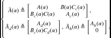
where  ,
, ![]() and
and
Before proceeding, we give the following definitions.
Definition 6.2.1 The closed-loop system in (6.3a)–(6.3c) with ω(t) = 0 is said to be exponentially stable under α if its solution ξ(t) satisfies
where η ≥ 1 and λ > 0 are two real constants, and
Definition 6.2.2 For β > 0 and γ > 0, the closed-loop system in (6.3a)–(6.3c) is said to be exponentially stable with a weighted ![]() -
-![]() performance γ, if under α it is exponentially stable with ω(t) = 0, and under zero initial condition, that is, ϕ(t) = 0, t ∈ [ − d, 0], for any nonzero
performance γ, if under α it is exponentially stable with ω(t) = 0, and under zero initial condition, that is, ϕ(t) = 0, t ∈ [ − d, 0], for any nonzero ![]() , it holds that
, it holds that
Therefore, the ![]() -
-![]() DOF control problem can be formulated as follows: for switched state-delayed hybrid systems (6.1a)–(6.1d) and a prescribed performance level γ > 0, determine DOF controllers in the form of (6.2a)–(6.2b) such that the resulting closed-loop system in (6.3a)–(6.3c) is exponentially stable with a weighted
DOF control problem can be formulated as follows: for switched state-delayed hybrid systems (6.1a)–(6.1d) and a prescribed performance level γ > 0, determine DOF controllers in the form of (6.2a)–(6.2b) such that the resulting closed-loop system in (6.3a)–(6.3c) is exponentially stable with a weighted ![]() -
-![]() performance level γ.
performance level γ.
6.2.2 Main Results
First, we will investigate the exponential stability and the weighted ![]() -
-![]() performance for the closed-loop system (6.3a)–(6.3c), and give the following result.
performance for the closed-loop system (6.3a)–(6.3c), and give the following result.
Theorem 6.2.3 Given constants β > 0 and γ > 0, suppose that there exist matrices P(i) > 0, Q(i) > 0, R(i) > 0, X(i), Y(i), and Z(i) such that for ![]() ,
,
where ![]() and
and

Then, the closed-loop system in (6.3a)–(6.3c) is exponentially stable with a weighted ![]() -
-![]() performance level γ for any switching signal with average dwell time satisfying
performance level γ for any switching signal with average dwell time satisfying ![]() , where μ ≥ 1 satisfies
, where μ ≥ 1 satisfies
Moreover, an estimate of the state decay is given by
where
Proof. Choose a Lyapunov function of the following form:
where P(α) > 0, Q(α) > 0, and R(α) > 0, ![]() are to be determined. Then, as with the solution of system (6.3a)–(6.3c) for a fixed α, it follows that
are to be determined. Then, as with the solution of system (6.3a)–(6.3c) for a fixed α, it follows that
On the other hand, Newton–Leibniz formula gives

Then for any appropriately dimensioned matrices  , we have
where  .
.
First, we will show the stability of the closed-loop system (6.3a)–(6.3c) with ω(t) = 0. By (6.11)–(6.12), we have
where

By Schur complement, LMI (6.6) implies
and noting
Thus considering (6.13)–(6.15), we have
For an arbitrary piecewise constant switching signal α, and for any t > 0, we let 0 = t0 < t1 < ⋅⋅⋅ < tk < ⋅⋅⋅, k = 1, 2, …, denote the switching points of α over the interval (0, t). As mentioned earlier, the ikth subsystem is activated when t ∈ [tk, tk + 1). Integrating (6.16) from tk to t gives
Using (6.7) and (6.10), at switching instant tk, we have
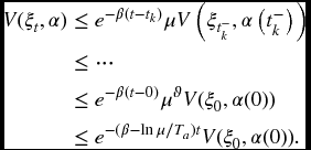
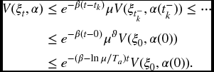
where t−k denotes the left limitation of tk. Therefore, it follows from (6.17)–(6.18), and noting ϑ = Nα(0, t) ≤ (t − 0)/Ta, that
Notice from (6.10) that V(ξt, α) ≥ a‖ξ(t)‖2 and V(ξ0, α(0)) ≤ b‖ξ(0)‖C2, where a and b are defined in (6.9). Considering (6.19) yields
which implies (6.8). By Definition 6.2.1 with t0 = 0, we know that the closed-loop system (6.3a)–(6.3c) with ω(t) = 0 is exponentially stable.
Now, we will establish the weight ![]() -
-![]() performance for the closed-loop system in (6.3a)–(6.3c). For any appropriately dimensioned matrix
performance for the closed-loop system in (6.3a)–(6.3c). For any appropriately dimensioned matrix ![]() , we have
, we have
where  and
and  . Considering (6.11) and (6.20), we have
where Π(α)≜Π1(α) + Π2(α) + ΠT2(α) + dΠT3(α)KTR(α)KΠ3(α) with Π1(α), Π2(α) and Π3(α) defined in (6.6). Note that

By Schur complement, LMI (6.6) implies
Thus, considering (6.21)–(6.23), we have
Let Γ(t)≜ − ωT(t)ω(t), then (6.24) can be rewritten as
As in the proof of stability above, integrating (6.25) from tk to t gives
Therefore, it follows from (6.18) and (6.26) and the relationship ϑ = Nα(0, t) ≤ (t − 0)/Ta that
Under zero initial condition, (6.27) implies
Multiplying both sides of (6.28) by ![]() yields
yields
Notice that Nα(0, t) ≤ t/Ta and Ta > T*a = ln μ/β, we have Nα(0, t)ln μ ≤ βt. Thus, (6.29) implies
Moreover, according to (6.10) and (6.30), we have

Thus, for any time t = t⋆ ≥ 0, we have
Since t⋆ denotes any time, it is also true that
From inequalities (6.31) and (6.32), we have
Using Schur complement again, LMI (6.6) yields
Combining (6.33) with (6.34) gives

that is, for any t⋆ ≥ 0,

Taking the supremum over t⋆ ≥ 0 yields (6.5), thus the weight ![]() -
-![]() performance has been established. The proof is completed. ▀
performance has been established. The proof is completed. ▀
Now, we are in a position to present a solution to the ![]() -
-![]() DOF control problem.
DOF control problem.
Theorem 6.2.4 Consider the switched state-delayed hybrid systems in (6.1a)–(6.1d). For given constants β > 0 and γ > 0, suppose that there exist matrices ![]() ,
, ![]() ,
, ![]() ,
, ![]() ,
, ![]() , R(i) > 0,
, R(i) > 0, ![]() ,
, ![]() ,
, ![]() ,
, ![]() ,
, ![]() ,
, ![]() ,
, ![]() ,
, ![]() ,
, ![]() ,
, ![]() ,
, ![]() ,
, ![]() , and
, and ![]() such that for
such that for ![]() ,
,

Then there exists a DOF controller in the form of (6.2a)–(6.2b), such that the closed-loop system in (6.3a)–(6.3c) is exponentially stable with a weighted ![]() -
-![]() performance γ for any switching signal with average dwell time satisfying
performance γ for any switching signal with average dwell time satisfying ![]() , where μ ≥ 1 satisfies
, where μ ≥ 1 satisfies
Moreover, a desired ![]() -
-![]() DOF controller realization is given by
DOF controller realization is given by
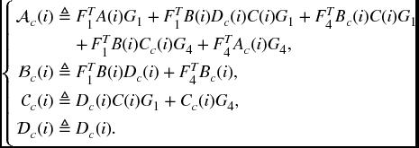
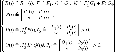
where

and

Proof. Introducing a slack matrix F, it is not difficult to see that the conditions in Theorem 6.2.3 are satisfied if there exist matrices P(i) > 0, Q(i) > 0, R(i) > 0 X(i), Y(i), Z(i), and F such that (6.6b) and the following conditions hold:
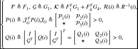
where

The condition in (6.38) implies (6.6a) in Theorem 6.2.3. To show this, we perform a projection transformation to (6.38) by diag{Λ(i), R(i), I} with

and thus imply (6.6a). Notice that if the condition in (6.38) holds, then matrix F is nonsingular, so we can let the matrix F be partitioned as
As we are considering a full-order DOF controller, F4 and G4 are both square. Without loss of generality, we assume that F4 and G4 are nonsingular (if not, F4 and G4 may be perturbed respectively by matrices ΔF4 and ΔG4 with sufficiently small norms such that F4 + ΔF4 and G4 + ΔG4 are nonsingular and satisfy (6.38)). Then, we can define the following matrices, which are also nonsingular,

Notice that
Performing a congruence transformation on (6.38) by matrix ![]() with
with ![]() , we have
, we have
where
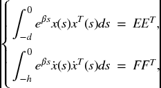
Define the following matrices:
and
LMI (6.42) implies
(6.35a) by considering (6.4), (6.39)–(6.41), and (6.43)–(6.45). Moreover, performing a congruence transformation on (6.6b) by matrix ![]() , we have
, we have

which is (6.35b) by noting (6.4) and (6.44). In addition, considering the conditions in (6.7) together (6.44) implies (6.36). Finally, considering (6.45) together with (6.44) yields (6.37). This completes the proof. ▀
Remark 6.1 In the proof of Theorem 6.2.4, we used conditions (6.38) and (6.6b), and not (6.6a)–(6.6b), to solve the ![]() -
-![]() DOF control problem. The reason is that there is no product term between the parameter-dependent Lyapunov matrices and the system dynamic matrices in (6.38); this separation is crucial to solving the
DOF control problem. The reason is that there is no product term between the parameter-dependent Lyapunov matrices and the system dynamic matrices in (6.38); this separation is crucial to solving the ![]() -
-![]() DOF control problem. ♦
DOF control problem. ♦
Remark 6.2 To solve the parameters of the DOF controller in (6.37), matrices F4 and G4 should be available in advance, and they can be obtained by taking any full rank factorization of ![]() (derived from
(derived from ![]() ). ♦
). ♦
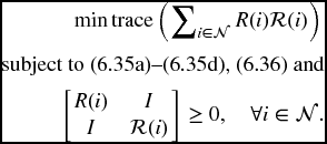
Note that the obtained conditions in Theorem 6.2.4 are not all of LMI form because of (6.35e), which can not be solved directly using LMI procedures. Now, using the CCL method [66], we suggest the following minimization problem involving LMI conditions instead of the original nonconvex feasibility problem formulated in Theorem 6.2.4.
Problem DOFC-SDS (DOF control of switched delayed systems):
If the solution of the aforesaid minimization problem is Nn, then the conditions in Theorem 6.2.4 are solvable. We suggest the following algorithm to solve Problem DOFC-SDS.
Algorithm DOFC-SDS
- Step 1. Find a feasible set

 satisfying (6.35a)–(6.35d), (6.36), and (6.46). Set κ = 0.
 - Step 2. Solve the following optimization problem:
and denote f* as the optimized value.

- Step 3. Substitute the obtained matrix variables

 into (6.42). If (6.42) is satisfied, with
for a sufficiently small scalar δ > 0, then output the feasible solutions


 , and EXIT.
 - Step 4. If
 where
where  is the maximum number of iterations allowed, so EXIT.
 - Step 5. Set
 . Let
. Let 
 , and go to Step 2.
6.2.3 Illustrative Example
Example 6.2.5 Consider system (6.1a)–(6.1d) with N = 2 and the following parameters:
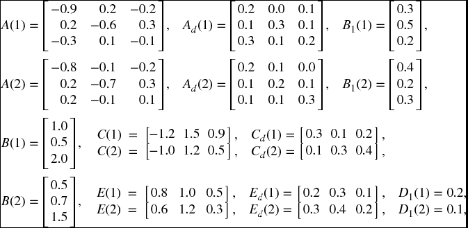
and d(t) = 0.9 + 0.3sin (t), β = 0.5. A straightforward calculation gives d = 1.2 and τ = 0.3. It can be checked that the switched state-delayed hybrid system in (6.1a)–(6.1d) with u(t) = 0 and the above parameters is unstable for switching signal given in Figure 6.1
(which is generated randomly; here, ‘1’ and ‘2’ represent the first and second subsystems, respectively) – the states of open-loop system are shown in Figure 6.2
with the initial condition given by ![]() , t ∈ [ − 1.2, 0].
, t ∈ [ − 1.2, 0].
Our aim is to design an ![]() -
-![]() DOF controller in the form of (6.2a)–(6.2b), such that the closed-loop system is exponentially stable with a weighted
DOF controller in the form of (6.2a)–(6.2b), such that the closed-loop system is exponentially stable with a weighted ![]() -
-![]() performance. Setting μ = 1.01 (in this case,
performance. Setting μ = 1.01 (in this case, ![]() , thus we can choose Ta ≥ 0.02) and solving Problem DOFC-SDS using Algorithm DOFC-SDS, it follows that the minimized feasible γ is γ* = 1.1726, and
, thus we can choose Ta ≥ 0.02) and solving Problem DOFC-SDS using Algorithm DOFC-SDS, it follows that the minimized feasible γ is γ* = 1.1726, and
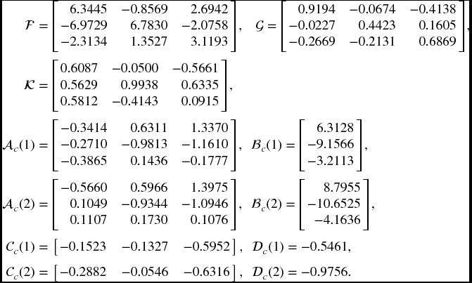
Setting F4 = I, then ![]() from
from ![]() in Remark 6.2.3. Therefore, by (6.37) we have
in Remark 6.2.3. Therefore, by (6.37) we have

To show the effectiveness of the designed ![]() -
-![]() DOF controller through simulation, let the exogenous disturbance input be ω(t) = exp ( − t)sin (t). Figure 6.3 gives the states of the closed-loop system, and Figure 6.4 depicts the states of the DOF controller.
DOF controller through simulation, let the exogenous disturbance input be ω(t) = exp ( − t)sin (t). Figure 6.3 gives the states of the closed-loop system, and Figure 6.4 depicts the states of the DOF controller.

Figure 6.1 Switching signal

Figure 6.2 States of the open-loop system

Figure 6.3 States of the closed-loop system

Figure 6.4 States of the DOF controller
6.3 Guaranteed Cost DOF Controller Design
6.3.1 System Description and Preliminaries
Consider a class of switched neutral delay systems of the form
where x(t) ∈ Rn is the system state vector, y(t) ∈ Rp is the measured output, and u(t) ∈ Rm is the control input. ![]() (denoted by α for simplicity) is the switching signal defined as the same in the previous section. h ≥ 0 is the constant neutral delay and d(t) denotes the time-varying delays satisfying 0 ≤ d(t) ≤ d and
(denoted by α for simplicity) is the switching signal defined as the same in the previous section. h ≥ 0 is the constant neutral delay and d(t) denotes the time-varying delays satisfying 0 ≤ d(t) ≤ d and ![]() , where d and τ are two known constants. φ(t) is a differentiable vector-valued initial function on
, where d and τ are two known constants. φ(t) is a differentiable vector-valued initial function on ![]() with
with ![]() .
.
For each possible value α = i ![]() , we denote the system matrices associated with mode i by A(i) = A(α), Ad(i) = Ad(α), Ah(i) = Ah(α), B(i) = B(α), C(i) = C(α), and Cd(i) = Cd(α), where A(i), Ad(i), Ah(i), B(i), C(i), and Cd(i) are constant matrices. Corresponding to the switching signal α, we have the switching sequence
, we denote the system matrices associated with mode i by A(i) = A(α), Ad(i) = Ad(α), Ah(i) = Ah(α), B(i) = B(α), C(i) = C(α), and Cd(i) = Cd(α), where A(i), Ad(i), Ah(i), B(i), C(i), and Cd(i) are constant matrices. Corresponding to the switching signal α, we have the switching sequence ![]() with t0 = 0, which means that the ikth subsystem is activated when t ∈ [tk, tk + 1).
with t0 = 0, which means that the ikth subsystem is activated when t ∈ [tk, tk + 1).
Here, we are interested in designing a DOF controller of a general structure described by
where xc(t) ∈ Rn is the controller state vector; Ac(α), Bc(α), and Cc(α) are appropriately dimensioned constant matrices to be determined later.
Augmenting the model of (6.47a)–(6.47c) to include the states of the DOF controller in (6.48a)–(6.48b), we obtain the following closed-loop system:
where  ,
, ![]() and
and
Associated with the closed-loop system (6.49a)–(6.49b) is the following cost function:
where U > 0 and W > 0 are given matrices.
We now introduce the following definitions before presenting our main results in this section.
Definition 6.3.1 Consider the switched neutral delay system in (6.47a)–(6.47c). If there exists a DOF controller u(t) in the form of (6.48a)–(6.48b) and a positive scalar ![]() such that the closed-loop system in (6.49a)–(6.49b) is stable and the cost function in (6.51) satisfies
such that the closed-loop system in (6.49a)–(6.49b) is stable and the cost function in (6.51) satisfies ![]() , then
, then ![]() is said to be a guaranteed cost and u(t) is said to be a guaranteed cost DOF controller for the switched hybrid system in (6.47a)–(6.47c).
is said to be a guaranteed cost and u(t) is said to be a guaranteed cost DOF controller for the switched hybrid system in (6.47a)–(6.47c).
Definition 6.3.2 The closed-loop system in (6.49a)–(6.49b) is said to be exponentially stable under α if its solution ξ(t) satisfies
where η ≥ 1 and λ > 0 are two real constants, and
Therefore, the problem to be addressed can be formulated as follows: for system (6.47a)–(6.47c), develop a procedure to design a DOF controller u(t) in the form of (6.48a)–(6.48b) such that the closed-loop system in (6.49a)–(6.49b) is exponentially stable and the specified linear integral-quadratic cost function in (6.51) has an upper bound.
6.3.2 Main Results
We will first present a sufficient condition for the existence of the DOF controller in (6.48a)–(6.48b), then give a parameterized representation of the controller in terms of the feasible solutions to a certain set of LMIs.
Theorem 6.3.3 Consider the closed-loop system in (6.49a)–(6.49b). For a given constant β > 0, suppose there exist matrices P(i) > 0, Q(i) > 0, and R(i) > 0 such that for ![]() ,
,
where

Then the closed-loop system in (6.49a)–(6.49b) is exponentially stable and the cost function (6.51) has the bound of
for any switching signal with average dwell time satisfying ![]() , where μ ≥ 1 satisfies
, where μ ≥ 1 satisfies
Moreover, an estimate of the state decay is given by
where
Proof. Choose a Lyapunov function of the following form:
where P(α) > 0, Q(α) > 0, and R(α) > 0 (![]() ) are to be determined. Then, as with the solution of the closed-loop system in (6.49a)–(6.49b) for a fixed α, we have
) are to be determined. Then, as with the solution of the closed-loop system in (6.49a)–(6.49b) for a fixed α, we have

Thus,
where  and
and
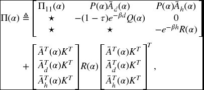
with Π11(α) defined in (6.52). It can be seen from (6.52) that Π(α) < 0, which implies
Now, for an arbitrary piecewise constant switching signal α, and for any t > 0, we let 0 = t0 < t1 < ⋅⋅⋅ < tk < ⋅⋅⋅, k = 1, …, denote the switching points of α over the interval (0, t). As mentioned earlier, the ikth subsystem is activated when t ∈ [tk, tk + 1). Integrating (6.58) from tk to t gives
Using (6.54) and (6.57), at switching instant tk, we have
Therefore, it follows from (6.59)–(6.60) and the fact ϑ = Nα(0, t) ≤ (t − 0)/Ta that
It can be shown from (6.57) that there exist scalars a > 0 and b > 0 such that the following holds:
where a and b are defined in (6.56). Combining (6.61) and (6.62) yields
which implies (6.55). By Definition 6.3.2 with t0 = 0, the closed-loop system in (6.49a)–(6.49b) is exponentially stable.
However, it can be seen from (6.52) that
where Ψ(α) is as defined previously. The above inequality implies
Thus, we have
Moreover, by integrating both sides of (6.63) from 0 to ∞ and using the initial condition, we obtain

The desired result follows Definition 6.3.1, thus the proof is completed. ▀
Now, we present a solution to the guaranteed cost DOF control problem for the switched neutral delay system in (6.47a)–(6.47c).
Theorem 6.3.4 Consider the switched neutral delay system in (6.47a)–(6.47c). For a given constant β > 0, suppose there exist matrices ![]() ,
, ![]() ,
, ![]() ,
, ![]() ,
, ![]() , R(i) > 0,
, R(i) > 0, ![]() ,
, ![]() ,
, ![]() ,
, ![]() ,
, ![]() ,
, ![]() ,
, ![]() , and
, and ![]() such that for
such that for ![]() ,
,

where

Then there exists a DOF controller in the form of (6.48a)–(6.48b), such that the closed-loop system in (6.49a)–(6.49b) is exponentially stable and the cost function (6.51) has the bound of
for any switching signal with average dwell time satisfying ![]() , where μ ≥ 1 satisfies
, where μ ≥ 1 satisfies
Moreover, if the above conditions are feasible, then a desired DOF controller realization is given by
Proof. By Theorem 6.3.3 and introducing a slack matrix F, it is not difficult to see that the conditions in Theorem 6.3.3 are satisfied if there exist matrices P(i) > 0, Q(i) > 0, R(i) > 0, and F such that the following LMI condition holds:
where

The above can be verified by performing a projection transformation on (6.68) by

and we can obtained (6.52).
In what follows, we will use (6.68), rather than (6.52), to solve the DOF control problem because there is no product term between the parameter-dependent Lyapunov matrix and the system dynamic matrix in (6.68), which is crucial to solving the present problem.
Notice that if the condition in (6.68) holds, then matrix F is nonsingular. Let the matrix F and its inverse matrix be partitioned respectively as
Without loss of generality, we assume that F4 and G4 are nonsingular – if not, F4 and G4 may be perturbed respectively by matrices ΔF4 and ΔG4 with sufficiently small norms such that F4 + ΔF4 and G4 + ΔG4 are nonsingular and satisfy (6.68).
Define the following matrices that are also nonsingular:
Noticing that ![]() ,
, ![]() , and F1G1 + F2G4 = I, and performing a congruence transformation on (6.68) by
, and F1G1 + F2G4 = I, and performing a congruence transformation on (6.68) by ![]() , we obtain
, we obtain
where

Define the following matrices:
It can be easily seen from (6.72) that ![]() and
and ![]() . Also, we define
. Also, we define
Thus, by considering (6.50), (6.69)–(6.70) and (6.72)–(6.73), we have
Substituting (6.74) into (6.71) implies (6.64a).
Moreover, considering (6.54) together with (6.72), gives (6.66), and considering (6.73) together with (6.72), yields (6.67). Finally, considering the zero initial condition of xc(t), that is, xc(0) = 0, we have

Therefore, replacing ξT(0)P(i0)ξ(0) and Q(i0) with ![]() and
and ![]() in (6.53) of
Theorem 6.3.3, respectively, supplies (6.65). This completes the proof. ▀
in (6.53) of
Theorem 6.3.3, respectively, supplies (6.65). This completes the proof. ▀
Remark 6.3 Notice that there exist product terms between the Lyapunov and system matrices in the LMI condition (6.52) of Theorem 6.3.3, which will make it difficult to solve the DOF controller synthesis problem. Hence, in the proof of Theorem 6.3.4, we have made a decoupling between the Lyapunov and system matrices by introducing a slack matrix variable F, and then obtained a new condition in (6.68). Although the new condition might have introduced some conservativeness, owing to the common matrix variable F, the introduced decoupling technique enables us to obtain a more easily tractable condition (6.68) for synthesis of the DOF controller. ♦
Remark 6.4 To solve the parameters of the DOF controller in (6.67), the matrices F4 and G4 should be available in advance, which can be obtained by taking any full rank factorization of ![]() (derived from
(derived from ![]() ).
).
Remark 6.5 Theorem 6.3.4 gives a set of DOF controllers characterized in terms of the solutions to
(6.64a)–(6.64d) and (6.66), and (6.67) parameterizes the set of DOF controllers. Each controller ensures the exponential stability of the resulting closed-loop system and an upper bound on the cost function given by (6.65). In view of this, it is desirable to find one which minimizes the upper bound ![]() in (6.65). ♦
in (6.65). ♦
The following theorem presents a method of selecting an optimal DOF controller minimizing the upper bound of the guaranteed cost (6.65).
Theorem 6.3.5 Consider the switched neutral delay system in (6.47a)–(6.47c) and cost function (6.51). For a given constant β > 0, suppose the following optimal problem:
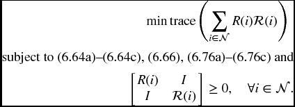
subject to (6.64a)–(6.64d), (6.66) and

has a feasible solution for ![]() ,
, ![]() ,
, ![]() ,
, ![]() ,
, ![]() , R(i) > 0,
, R(i) > 0, ![]() ,
, ![]() ,
, ![]() ,
, ![]() ,
, ![]() ,
, ![]() ,
, ![]() ,
, ![]() ,
, ![]() ,
, ![]() (
(![]() ), and a scalar ϵ > 0, where
), and a scalar ϵ > 0, where
with E and F being given constant matrices with appropriate dimensions. Then, the corresponding DOF controller in the form of (6.48a)–(6.48b) with (6.67) is an optimal DOF controller with a guaranteed cost in the sense that the upper bound on the closed-loop cost function (6.65) is minimized under this controller.
Proof. The proof of this theorem is along the same lines as that of Theorem 6.3.4. By Schur complement, LMI
(6.76a) is equivalent to ![]() . However, noting (6.77), we have
. However, noting (6.77), we have
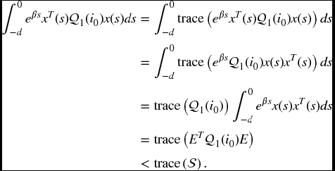
Moreover, it follows from (6.77) and ![]() that
that

Thus, according to (6.65), we have ![]() , and the minimization of
, and the minimization of ![]() implies the minimization of the guaranteed cost for the switched neutral delay system in (6.47a)–(6.47c). The optimality of the solution to the optimization problem (6.75) follows from the convexity of the objective function as well as the constraints. This completes the proof. ▀
implies the minimization of the guaranteed cost for the switched neutral delay system in (6.47a)–(6.47c). The optimality of the solution to the optimization problem (6.75) follows from the convexity of the objective function as well as the constraints. This completes the proof. ▀
Notice that the conditions in Theorem 6.3.5 are not all of LMI form because of (6.64d), hence they can not be solved directly using LMI procedures. Now, by using the CCL method again, we suggest the following minimization problem involving LMI conditions instead of the original nonconvex feasibility problem formulated in Theorem 6.3.5.
Problem DOFC-SNDS-GC (DOF control of switched neutral delay systems with a guaranteed cost):
The following algorithm is suggested to solve the Problem DOFC-SNDS-GC.
Algorithm DOFC-SNDS-GC
- Step 1. Find a feasible set

 satisfying
(6.64a)–(6.64c),
(6.66), (6.76a)–(6.76c), and (6.78). Set κ = 0.
 - Step 2. Solve the following optimization problem:
and denote f* as the optimized value.

- Step 3. Substitute the obtained matrix variables

 into (6.71). If (6.71) is satisfied, with
for a sufficiently small scalar δ > 0, then output the feasible solutions

 , so EXIT.
- Step 4. If
 where
where  is the maximum number of iterations allowed, so EXIT.
- Step 5. Set κ = κ + 1,


 , and go to Step 2.
6.3.3 Illustrative Example
Example 6.3.6 Consider system (6.47a)–(6.47c) with N = 2 (that is, there are two subsystems) and the related parameters are given as follows:

with d(t) = 0.7 + 0.3sin (t) and β = 0.5. A straightforward calculation gives d = 1.0 and τ = 0.3. It can be checked that the system in (6.47a)–(6.47c) with u(t) = 0 and the above parameters is unstable for switching signal given in Figure 6.5
(which is generated randomly; here, ‘1’ and ‘2’ represent the first and second subsystems, respectively), and the states of open-loop system are shown in Figure 6.6
with the initial condition given by ![]() , θ ∈ [ − 1, 0]. In view of this, our aim is to design a DOF controller u(t) in the form of (6.48a)–(6.48b), such that the closed-loop system is exponentially stable and the specified linear integral-quadratic cost function in (6.51) has an upper
bound.
, θ ∈ [ − 1, 0]. In view of this, our aim is to design a DOF controller u(t) in the form of (6.48a)–(6.48b), such that the closed-loop system is exponentially stable and the specified linear integral-quadratic cost function in (6.51) has an upper
bound.
Setting μ = 1.01 (thus ![]() ) and U = diag{0.1, 0.1, 0.1}, W = 0.5, i0 = 1, we solve Problem DOFC-SNDS-GC by Algorithm DOFC-SNDS-GC, and obtain
) and U = diag{0.1, 0.1, 0.1}, W = 0.5, i0 = 1, we solve Problem DOFC-SNDS-GC by Algorithm DOFC-SNDS-GC, and obtain

Setting F4 = I, we have ![]() by Remark 6.4. Therefore, it follows from (6.67) that
by Remark 6.4. Therefore, it follows from (6.67) that

Consequently, the optimal guaranteed cost of the closed-loop system is ![]() . The states of the closed-loop system are given in Figure 6.7
and the DOF control input is shown in Figure 6.8.
. The states of the closed-loop system are given in Figure 6.7
and the DOF control input is shown in Figure 6.8.

Figure 6.5 Switching signal

Figure 6.6 States of the open-loop system

Figure 6.7 States of the closed-loop system

Figure 6.8 Control input
6.4 Conclusion
In this chapter, the DOF controller design problem has been investigated for continuous-time switched hybrid systems with time-varying delay. Two independent problems have been considered: one is the ![]() -
-![]() DOF controller design for switched hybrid systems with time-varying delay, and the other is the guaranteed cost DOF controller design for switched hybrid systems with neutral delay. By using the average dwell time approach and the piecewise Lyapunov function technique, some delay-dependent sufficient conditions have been proposed for the existences of the
DOF controller design for switched hybrid systems with time-varying delay, and the other is the guaranteed cost DOF controller design for switched hybrid systems with neutral delay. By using the average dwell time approach and the piecewise Lyapunov function technique, some delay-dependent sufficient conditions have been proposed for the existences of the ![]() -
-![]() DOF controller and the guaranteed cost DOF controller, respectively. Then, the corresponding solvability conditions for the desired
DOF controller and the guaranteed cost DOF controller, respectively. Then, the corresponding solvability conditions for the desired ![]() -
-![]() DOF controller and the guaranteed cost DOF controller have also been established, respectively, by using the linearizing variables transforms approach. Numerical examples have been provided to illustrate the effectiveness of the proposed design schemes.
DOF controller and the guaranteed cost DOF controller have also been established, respectively, by using the linearizing variables transforms approach. Numerical examples have been provided to illustrate the effectiveness of the proposed design schemes.
