
Chapter 11
Autodesk Maya Rendering
Rendering is the last step in creating your CG work. It’s the process by which the computer calculates the surface properties, lighting, shadows, movement, and shape of objects, and it saves a sequence of images. Although the computer does all the thinking at this point, you still need to set up your cameras and the render to get exactly what you want.
This chapter will show you how to render your scene using the Autodesk® Maya® Software renderer and mental ray® for Maya, and how to create reflections and refractions. In this chapter, you’ll use a wine bottle and a still life from previous chapters, and you’ll animate a camera to render a sequence.
- Set up your scenes for output through rendering
- Choose resolutions, image formats, and other settings for rendering
- Create and edit cameras
- Render with motion blur and know how to differentiate between the types of motion blur
- Set up and use mental ray
- Render in layers and compose them back together
- Set render layer overrides settings for specific needs
- Use Final Gathering in mental ray renders for indirect lighting workflows
- Properly use Ambient Occlusion to create detail in crevices and for contact shadows
- Apply an HDRI map as a lighting source
- Apply a displacement map to create finer detail in a model
Rendering Setup
When your lighting scene from the previous chapter is complete, you’ve had a celebration smoothie for your hard work, and you’re ready to start a render, you’ll need to set up how you want it rendered. Although this is the last part of the CG process, from now on you should be thinking about rendering throughout your production. When you create models and textures with the final image in mind and you gear the lighting toward showing off the scene elegantly, the final touches are relatively easy to set up.
Decide which of the render engines included with Maya you’ll use: Maya Software, Maya Hardware (or Hardware 2.0), mental ray for Maya (the most popular and what you started using in the previous chapter), or Maya Vector. Each engine has its own particular workflow and can yield entirely different results, although mental ray and Maya Software are close in appearance if you don’t use the special features of mental ray. The choice of a rendering method depends on the final look you want and sometimes on the number of machines and licenses with which you can render. Maya Software rendering comes with an unlimited number of licenses, which means you can render on any machine you have (with Maya installed), although you can work with the Maya application only on as many machines for which you have licenses. There are also third-party developers in the CG field that have created other render engines that plug right into Maya, such as V-Ray® for Maya, Maxwell, and Pixar’s RenderMan® for Maya.
No matter which renderer you use, the lighting and general setup are fairly common across the board. Even then, it’s a good idea to choose your render engine as you begin creating your scene. It’s best to begin with basic mental ray to pick up the fundamentals of lighting, texturing, and rendering before you venture into mental ray special features or try other renderers.
Regardless of the type of render, you need to specify a set of common attributes in the Render Settings window. Choose Window ⇒ Rendering Editors ⇒ Render Settings to open the Render Settings window. Figure 11-1 shows on the left the Render Settings window for the Maya Software renderer and its tabs: the Common tab and the Maya Software tab. You use the options in this window’s Common tab to set up all your rendering preferences, including the resolution, file type, frame range, and so forth.
Figure 11-1: The Render Settings window

The Common tab contains the settings common to all the rendering methods, such as image size. The Maya Software tab gives you access to render-specific attributes, such as quality settings, raytracing settings, motion blur, and so on.
If you switch the Render Using pull-down menu from the default Maya Software setting to mental ray, you’ll notice several tabs: Passes, Features, Quality, Indirect Lighting, and Options, as shown on the right in Figure 11-1. These tabs give you access to all the settings for the incredibly powerful mental ray renderer.
You may notice that some of the render engines like mental ray may not show up in the Render Settings window right away. In this case, the renderers’ respective plug-ins must be loaded first. I’ll discuss this further in the section “mental ray for Maya” later in this chapter.
Choosing a Filename
Rendered images are identified by a filename, a frame number, and an extension, in the form name.#.ext—for example, stillife.0234.tif.
In the File Name Prefix text box, enter the image sequence name. If you don’t enter anything in this text box, Maya automatically names your rendered images after your scene file (stillife in the example). This is the preferred naming convention; using it, you can immediately identify the scene file from which a particular image file was rendered.
In the Frame/Animation Ext drop-down list box, select name.#.ext to render out a sequence of files. If you leave this setting at the default of name.ext, only a single frame will render, no matter what the animation range is in the Time slider.
The extension portion of the image name is a three-letter abbreviation for the type of file you’re writing to disk to ensure that you can identify the file type.
Image Format
In the Image Format drop-down list box, select the type of image file you want to render. Maya will add the appropriate extension to the filename.
The image format you choose depends on your own preference and your output needs. For example, Joint Photographic Experts Group (JPEG) files may be great for the small file sizes preferred on the Internet, but their color compression and lack of alpha channel (a feature discussed later in this chapter) make them undesirable for most professional CG work beyond test renders.
It’s best to render a sequence of images rather than a movie file for two reasons. First, you want your renders to be their best quality with little or no image compression. Second, if a render fails during a movie render, you must re-render the entire sequence. With an image sequence, however, you can pick up where the last frame left off.
The best file type format to render to is Tagged Image File Format (TIFF). This format enjoys universal support, has little to no compression, and supports an alpha channel. Almost all image-editing and compositing packages can read Targa- and TIFF-formatted files, so either is a safe choice most of the time. For more on image formats, see Chapter 1, “Introduction to Computer Graphics and 3D.”
Frame Range
Maya defaults to the range 1–10, which you may need to change to render your entire sequence. You must choose a naming convention other than Name (Single Frame) to access the frame range. This is a common oversight when people first try to render their animations and see that only a single frame renders.
Enter the Start Frame and End Frame attributes for part of the sequence or the entire sequence. By specifying new start and end frames, you can render different portions of a sequence or pick up where a previous render left off.
The By Frame attribute specifies the intervals at which the sequence will render. For example, if you want to render only the odd-numbered frames, set the Start Frame attribute to 1, and set the By Frame attribute to 2. If you want to render only even-numbered frames, set Start Frame to 2, set By Frame to 2, and so on. Typically, you leave By Frame set to 1 so that Maya renders each frame.
The Frame Padding attribute and slider have to do with the way an operating system, such as Windows or Mac OS X, orders its files by inserting leading zeros in the frame number. For example, if Frame Padding is set to 4, the filename contains three leading zeros; therefore, frame 8 is name.0008.tif as opposed to name.8.tif (which is set to a padding of 1).
Large sequences of files are easier to organize if they all have a frame padding of at least 3. Figure 11-2 shows an image sequence without padding and with padding. The files without padding aren’t shown in numeric order.
Figure 11-2: Images rendered without frame padding (left). Frame padding makes file sequences easier to organize (right).

Camera and Channels
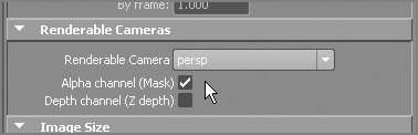
Under the Renderable Cameras heading, you choose the camera to render, and enable the Alpha and Depth channels.
Image files are composed of red, green, and blue channels. Each channel specifies the amount of the primary additive color (red, green, or blue, respectively) in the image. (See Chapter 1 for more on how computers define color.) Some file formats save a fourth channel, called the alpha channel. This channel defines the image’s transparency level. Just as the red channel defines how much red is in an area of the image, the alpha channel defines how transparent the image is when layered or composited on another image. If the alpha channel is black, the image is perfectly see-through. If the alpha channel is white, the image is solid and opaque. The alpha channel is also known as the matte. An object with some transparency like tinted glass will render with a gray alpha channel, as shown in Figure 11-3.
Figure 11-3: This wine bottle’s transparency renders with a gray alpha channel.

The alpha channel can be displayed in the Render View window. As discussed later in this chapter, your test renders also display in this window.
Most renders have the alpha channels selected, so leave the Alpha Channel (Mask) check box selected at all times, as shown in Figure 11-4. Note, however, that JPEG, Graphics Interchange Format (GIF), and Windows bitmap files don’t support alpha channels, regardless of whether the Alpha Channel (Mask) check box is selected.
Figure 11-4: Output an alpha channel.
Setting Resolution
The Width and Height attributes set the pixel size of the image to be rendered, a.k.a. the image resolution. In the Image Size section of the Render Settings window, you can select a resolution from the Presets drop-down list. The commonly used resolution for professional broadcast is 1920×1080 High Definition, which appears as HD 1080in the Presets list. To composite Maya CG into a home-shot digital video (DV) movie, you use the standard DV resolution of 720×480 to render your scene, but you must enter that resolution manually in the Width and Height fields. (For more on resolutions, see Chapter 1.)
The Device Aspect Ratio and Pixel Aspect Ratio attributes adjust the width of the image to accommodate certain professional output needs; you do not need to adjust them here.
The higher your resolution, the longer the scene will take to render. With large frame sequences, it’s advisable to render tests at half the resolution of the final output or less to save time. In addition to turning down the resolution for a test, you can use a lower-quality render.
Selecting a Render Engine
Maya allows you to select a render engine in the Render Settings window. Although mental ray for Maya is most commonly used, the other rendering methods give you flexibility in choosing a final look for your project.
Maya Software
Maya Software, the default software rendering method, can capture just about everything you want in your scene, from reflections to motion blur and transparencies. You can use the software rendering method in a couple of ways.
Using Raytracing
Raytracing, a topic introduced in Chapter 10, “Autodesk Maya Lighting,” is used to incorporate two optical effects into a rendering that the default software rendering method can’t handle. Raytracing traces rays of light from each light source to every object in the shot and then traces the light’s reflection from the object to the camera’s lens. This allows true reflections and refractions to appear in the render as well as highly defined shadows (for more on shadows, see Chapter 10).
You saw in the previous chapter that raytracing is also a vital component of mental ray for Maya as well as the Maya Software renderer.
As with raytraced shadows, raytraced reflections need to be enabled. To do so, click Raytracing in the Raytracing Quality section of the Maya Software tab in the Render Settings window. Unlike raytraced shadows, however, raytraced reflections need not be explicitly turned on through the lights.
As soon as raytracing is enabled, any reflective surface receives a true reflection of the objects and environment in the scene. Even objects with reflection maps reflect other objects in addition to their reflection maps. For more on reflection maps, see the section “Reflections and Refractions” later in this chapter.
Render Quality
With software rendering, the render quality depends most noticeably on anti-aliasing. Anti-aliasing is the effect produced when pixels appear to blur together to soften a jagged edge on an angled line. Increasing the anti-aliasing level of a render produces an image that has smoother angles and curves. The Render Settings window contains presets that specify this level and a few others to set the quality of your render. Follow these steps:
Figure 11-5 shows the fruit still life from Chapter 10 rendered with the Preview Quality preset and the same image with the Production Quality preset.
Figure 11-5: With Preview Quality (left), the edges of the fruit are jagged. With Production Quality (right), the jaggedness is gone.

Of course, the higher the quality, the longer the render will take. As you become more experienced, you’ll be better able to balance uncompromised quality with efficient render times.
Maya Hardware and Hardware 2.0
The hardware rendering method uses your graphic card’s processor to render the scene. Hardware renders are similar to what you may see when you play a 3D video game.
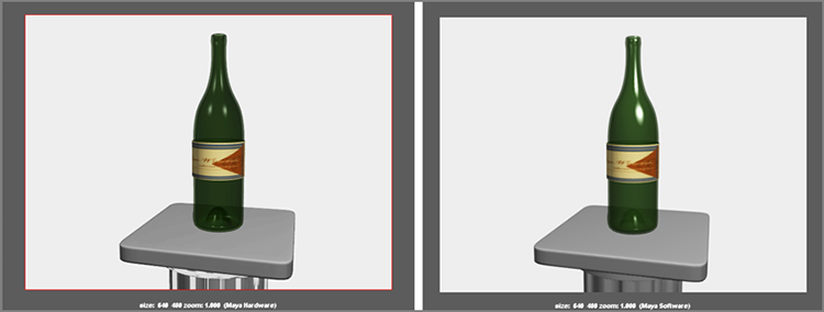
This method results in faster render times, but it lacks some of the features and quality you get from a software render. In Figure 11-6, the first image shows a wine bottle as rendered through hardware. The render time is blazingly fast, but the quality suffers. The second image shows the software render of the same frame. Hardware rendering becomes a good way to test-render a scene, although only some video cards fully support Maya Hardware rendering.
Figure 11-6: The hardware-rendered wine bottle (left) lacks some subtleties. The software-rendered wine bottle shows better specularity and surface detail (right).
To use the Maya Hardware renderer, in the Render Settings window, make sure Maya Hardware is selected in the Render Using drop-down list. To specify hardware quality, select a level from the Number Of Samples drop-down list on the Maya Hardware tab.
mental ray for Maya
mental ray for Maya has become a standard for rendering through Maya, supplanting the Maya Software renderer because of its stability and quality results. The mental ray for Maya rendering method can also let you emulate the behavior of light even more realistically than the other rendering methods, as you saw in the previous chapter’s Physical Sun and Sky exercise. Based on raytracing, mental ray takes the concept further by adding photon maps to the light traces. That is, it projects photon particles from lights and records their behavior and trajectory. The end result allows the phenomena of light caustics and bounce, also known as global illumination.
The mental ray for Maya renderer can be an advanced and intricate rendering language with shaders and procedures all its own. This chapter briefly covers one of the popular mental ray methods called Final Gather using an HDR lighting dome. To use mental ray, you still need to be experienced with the basics of lighting and rendering. At its base, mental ray will give you results similar to those of Maya Software, without any of the bells and whistles enabled.
Maya Vector
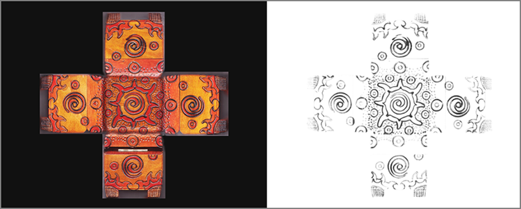
Vector rendering lets you render your objects with an illustrated or cartoon look. You can render “ink” outlines of your characters to composite over flat-color passes. Figure 11-7 shows the fruit still life rendered with Maya Vector. This rendering method is different from the Maya toon-shading feature, which is briefly covered in Chapter 12, “Autodesk Maya Dynamics and Effects.”
Figure 11-7: The fruit still life as a vector render

Maya Vector can output animated files in Adobe Flash format for direct use in web pages and animations, as well as Adobe Illustrator files and the usual list of image formats. To specify the attribute settings for Maya Vector, you use the Maya Vector tab in the Render Settings window (see Figure 11-8).
Figure 11-8: The Maya Vector rendering settings
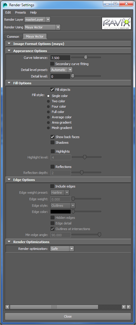
In the Fill Options section, click the Fill Objects check box, and select the number of colors for each object to set the look of the render. If you want the renderer to include an outline of the edges of your geometry, in the Edge Options section, click the Include Edges check box and set the line weights.
Previewing Your Render: The Render View Window
The Render View window automatically opens when you test-render a frame, as you’ve already seen in your work through this book. To open it manually, choose Window ⇒ Rendering Editors ⇒ Render View. Your current scene renders in the Render View window. Figure 11-9 shows the important icons in this window.
Figure 11-9: The Render View window

Saving/Loading an Image
Although you typically use the Render View window to test a scene, you can also use it to save single frames by choosing File ⇒ Save Image to save in any image formats supported in Maya. Likewise, choose File ⇒ Open Image to display any previously rendered image file in this window. If your task in Maya is to create a single frame, this is the best way to render and save it.
Keep/Remove Image
The Render View window is a prime place to see adjustments to various parts of your scene. You can store images in its buffer by clicking the Keep Image icon. When you do, a scroll bar appears at the bottom of the window, and you can scroll through any saved images. This is handy for making a change, rendering it, and scrolling back and forth between the old saved image and the new render to make sure the change is to your liking. You can store a number of images in the buffer. For a faster way to preview changes, use IPR rendering, as discussed next.
IPR Rendering
As you saw in Chapter 7, a fast way to preview changes to your scene is to use Maya Interactive Photorealistic Rendering (IPR). After you IPR-render a view panel, specify the region you want to tune by dragging a box around that area of the image in the Render View window. Maya updates that region every time you make a shader or lighting change to the scene. Figure 11-10 shows the decorative box as an IPR mental ray render as the color and specular levels are being fine-tuned against a wireframe snapshot of the model.
Figure 11-10: IPR rendering lets you fine-tune your textures and lighting with near-real-time feedback.

IPR is perfect for finding just the right lighting and specular levels. It will, however, register raytracing elements such as refractions and true reflections only if the scene is set to render through mental ray for Maya. Overall, IPR quality is fairly close to that of a full render while still allowing you to watch your tuning in near real time.
Reflections and Refractions
As you saw in Chapter 7, creating a “faked” reflection with a map for an object is pretty simple. To generate true reflections without the use of maps, however, you’ll need to enable raytracing in either Maya Software or mental ray for Maya. With raytracing, Maya reflects any objects in the scene that fall in the proper line of sight.
Raytraced Reflections
To enable raytraced reflections, use a material with a Reflections attribute, such as a Phong, and open the Render Settings window. Choose Maya Software, and on the Maya Software tab, click the Raytracing check box in the Raytracing Quality section. (See Figure 11-11.)
Figure 11-11: Enabling raytracing in Maya Software rendering
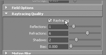
The sliders control the quality of the render by specifying how many times to reflect or refract for any given object. Setting Reflections to 2, for example, enables an object’s reflection in a second object to appear as part of its reflection in a third object.
The first image in Figure 11-12 shows the still life reflecting onto the surface of its table. In this case, Reflections is set to 1. If you increase Reflections to 2, however, you’ll see the reflections of the pieces of fruit in each other also reflecting in the surface of the table.
Figure 11-12: Reflections set to 1 (left); Reflections set to 2 (right)
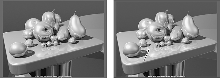
Notice the difference in the reflections of the fruit in the table between the two renders. Raytraced reflections can consume valuable render resources and time, so it’s a good idea to make your scene efficient.
You can control the number of reflections on a per-object basis as opposed to setting limits on the entire scene through the Render Settings window. To access a shader’s reflection limits, select the shader in the Hypershade, and open the Attribute Editor. In the Raytrace Options section, drag the Reflection Limit slider to set the maximum number of reflections for that shader. The lower value (either this value or the Reflections value in the Render Settings window) dictates how many reflections are rendered for every object attached to that shader. The default shader reflection limit is 1, so make sure you change the Reflections value as well as each shader’s value if you want more than one level of reflection.
Furthermore, you may not want some objects to cast reflections in a scene with raytraced reflections. To specify that an object doesn’t cast reflections, select the object in a Maya panel, and open the Attribute Editor. In the Render Stats section, clear the Visible In Reflections check box.
Rendering Refractions
Refractions are also a raytraced-only ability. Refractions require that an object be semitransparent so that you can see through it to the object (or objects) behind it being refracted. To control refractions, use the shader.
To enable refractions, select the appropriate shader in the Hypershade, and open the Attribute Editor. In the Raytrace Options section, click the Refractions check box. Now you need to set a refractive index for the shader and a refraction limit, similar to the reflection limit.
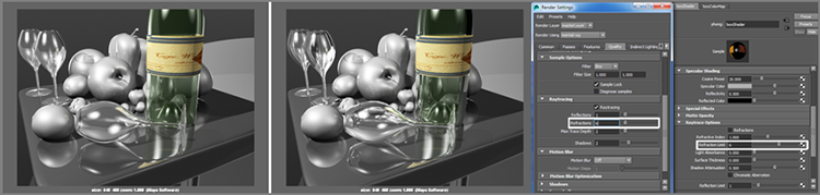
The refractive index must be greater or less than 1 to cause a refraction. Typically, a number within 0.2 of 1 is perfect for most refraction effects. The first image in Figure 11-13 is raytraced with a refractive index of 1.2 on the wine bottle and glasses; the second image has a refractive index of 0.8 on both bottle and glasses.
Figure 11-13: Refractive index of 1.2 (left render); refractive index of 0.8 (middle render); setting the refraction quality in the Render Settings and the shader (right two windows)
You can specify whether an object is visible in a refracting object by clicking or clearing the Visible In Refractions check box in the Render Stats section of the object’s Attribute Editor.
When rendering refractions, make sure the Refractions attribute under Raytracing Quality in the Maya Software tab of the Render Settings is set to at least 2 or higher; otherwise, your refraction may not appear properly. For mental ray, it is the Refractions attribute found under the Raytracing heading on the Quality tab, as shown in Figure 11-13 (right). You will also need to set the Refraction Limit found under the Raytrace Options heading in the Attribute Editor for the refractive shader in question.
Using Cameras
Cameras capture all the animation fun in the scene. The more you know about photography, the easier these concepts are to understand.
The term camera, in essence, refers to the perspective view. You can have as many cameras in the scene as you want, but it’s wise to have a camera you’re planning to render with placed to frame the shot and a different camera acting as the perspective work view so you can move around your scene as you work. The original persp view panel fits that latter role well, although it can be used as a render camera just as easily.
You can also render any of your work windows to test-render orthogonal views of your model the same way you render a perspective view.
Creating a Camera
The simplest way to create a new camera is to choose Panels ⇒ Perspective ⇒ New, as you’ve seen in a previous exercise. This creates a new camera node in Maya and sets that active panel to its view.
You can select a camera and transform it (move it, rotate it, scale it) just as you would select and transform any other object in Maya to be animated or positioned. Furthermore, you can move a camera and rotate it using the Alt/Option key and mouse button combinations.
For example, click inside a new Maya Scene Perspective window to make it active. Select that view’s camera by choosing View ⇒ Select Camera. The camera’s attributes appear in the Channel Box. Try moving the view around using the Alt/Option key and mouse button combinations. Notice how the attributes change to reflect the new position and rotation of the camera. You can animate the camera—for example, zoom in or out or pan across the scene—by setting keyframes on any of these attributes.
Camera Types
You can create three types of nonstereo cameras for your scene: Camera; Camera And Aim; and Camera, Aim, And Up (also known as single-node, two-node, and three-node cameras, respectively). To create any of these cameras, choose Create ⇒ Cameras. You can also change the type of these cameras at any time through the Attribute Editor. The other two options for creating cameras are Stereo Camera and Multi Stereo Rig to allow for a stereoscopic effect, although they aren’t covered in this book.
The single-node camera (Camera) is the most common (see Figure 11-14). This camera consists of a single camera node that you move and rotate as you would any other object for proper positioning. The persp view panel’s camera is a single-node camera.
Figure 11-14: A single-node camera
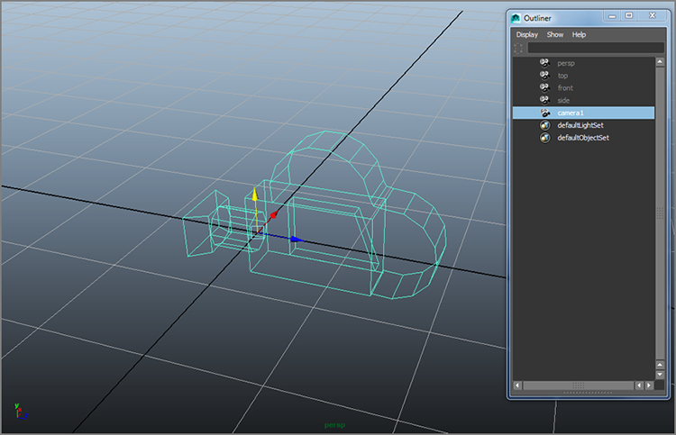
The two-node camera (Camera And Aim) consists of the camera node and an aim node. You use the aim node to point the camera as opposed to rotating it to orient it properly. This is useful for animating a camera following an object. You animate the movement of the aim node to follow your object much as you’d follow a car around a racetrack. The camera pivots to follow its aim point and, hence, the object. (See Figure 11-15.)
Figure 11-15: A two-node camera

The three-node camera (Camera, Aim, And Up) has a camera node, an aim node, and an up node. The additional up node is to orient the camera’s up direction. This gives you the ability to animate the side-to-side rotation of the camera as well as its aim direction. (See Figure 11-16.)
Figure 11-16: A three-node camera

Camera Attributes
As an example, set your project to Lighting, and download the still_life_render_v02.mb scene from the Lighting project on the book’s web page, www.sybex.com/go/introducingmaya2014. You’ll see a green box in the persp view panel that displays the resolution (set to 640×480) and the name of the camera (camera1).
Special attributes control the function of camera nodes. To set these attributes, follow these steps:
Figure 11-17: The Attribute Editor for the persp camera

Focal Length
The Focal Length attribute specifies the length of the lens. The lower the focal length (a.k.a. short lens), the wider the view. At very low numbers, however, the image is distorted, as you can see in the comparison in Figure 11-18. The higher the focal length, the closer the subject seems to the camera.
Figure 11-18: Different focal lengths

Although adjusting the Focal Length attribute of a camera zooms in and out, it isn’t the same as moving the camera closer to your subject using the Alt+right-click procedure to zoom in view panels (which is called trucking the camera). Focal-length zooming can create optical distortions, such as can be created with a fish-eye lens.
If you need to match some CG element in Maya to a photograph or video that you’ve imported as an image plane, set your camera’s focal length to match that of the real camera used for the background photo.
Clipping Planes
All cameras in Maya have clipping planes that restrict the amount of information that can be seen through them. The clipping plane is defined by the Near Clip Plane and Far Clip Plane attributes. These set the minimum and maximum distances, respectively, of the clipping plane. Any object or portion of an object that passes beyond these distances won’t show in the window and should not render.
If you notice objects disappearing as you move your camera and create a scene, it may be because of the clipping plane. Increase the Far Clip Plane attribute, and the objects should reappear in the view.
Film Back
The Film Back attributes concern the type of output you’ll be dealing with after your renders are finished and you’re ready to put your animation on tape, DVD, film, or what have you.
Overscan
Found in the Display Options section for the camera’s Attribute Editor, Overscan lets you resize the view without changing the film gate that will render. For example, the scene on the left in Figure 11-19 is set up with an Overscan setting of 1.3, allowing you to see more than what will render, which is defined by the outline box. The scene on the right in Figure 11-19 is set up with an Overscan setting of 2, which increases even more how much you see in the camera1 panel but doesn’t change the view when rendered.
Figure 11-19: Overscan settings define how much you can see of your scene in the camera but not how much renders in the image.

You can turn the green box in the panel on and off through the camera’s Attribute Editor. Also in the Display Options section are Display Film Gate and Display Resolution check boxes, shown in Figure 11-20. Ideally, these two green boxes should align perfectly in the view pane. If the resolution box (the solid green line) doesn’t line up with the film gate box (the dashed green line), change your film gate selection to match the resolution’s aspect ratio in the Render Settings window. A resolution of 640×480, for example, has an aspect ratio of 1.33, the same as the 35mm TV Projection film gate currently selected for this scene.
Figure 11-20: Camera display options

Environment
In the Environment section, you’ll find attributes to adjust the background color that renders and to create an image plane, as shown in Figure 11-21.
Figure 11-21: Adjusting the camera’s environment and creating camera image planes
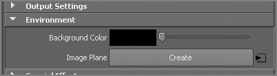
If you want to use a solid color as the camera’s background when you render, click the color swatch next to Background Color to change the background color in your renders using the Color Chooser. The slider allows you to control the value, or brightness, of the current color. Neither changes the background color of your view panels, however.
Camera Image Planes
A camera image plane isn’t like the reference planes you used for modeling the red wagon in Chapter 6, “Practical Experience.” In this case, an image plane is created to be a background specific for that particular camera or view panel, but it’s typically also used as a reference, much like the planes you created and mapped in Chapter 6. Camera image planes are useful when you’re matching your scene to existing footage or an image. For example, if you need to animate a flying saucer into a home video of a family gathering, you would import the video as an image sequence into Maya through a perspective camera to be able to line up your UFO properly to zap your cousins.
You can import an image plane by clicking the Create button in the Environment section of the Attribute Editor (see Figure 11-21) or directly through a view panel’s menu, as you’ll see in the next exercise.
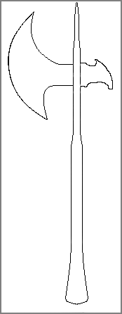
In this exercise, you’ll learn how to import a sketch of an axe into the Front view panel for a modeling assignment. (You won’t actually model the axe, however.) The image, a sketch of a simple axe design, is to be used as a template for outlining the model. You can find the file Axe_outline_1.tif in the Sourceimages folder of the Axe project on the companion web page; it’s shown in Figure 11-22.
Figure 11-22: An image to import as a camera image plane
Follow these steps:
Figure 11-23: Importing a camera image plane into the Front view panel

Now you’d be ready to trace the outline of the axe easily in the Front view panel, if you were going to model the axe.
Image Plane Sequence
A movie file or a sequence of files can also be brought in to animate or to track motion (a.k.a. matchmoving) as a camera image plane. It’s generally best to use a frame sequence, however. When you bring in an image for an image plane, check the Use Image Sequence box in the image plane’s Attribute Editor window, as shown in Figure 11-24. Maya will automatically load the image to correspond to the frame number in the scene. For example, at frame 29 in your Maya animation, Maya loads frame 29 of your image sequence. But your image file sequence must be numbered correctly (such as filename.###.tif). You can import an image plane into any perspective view in exactly the same way.
Figure 11-24: Importing a sequence of image files as a camera image plane

Motion Blur
Motion blur is an optical phenomenon that occurs when an object moves quickly in front of a camera: the object looks blurred as it crosses the frame. Maya Software rendering renders motion blur in two ways—2D blur or 3D blur—although neither will render as reflections.
- In the 2D blur process, Maya calculates after the frame is rendered. Any objects moving in the frame are blurred with a 2D filter effect. The 2D blur is effective for most applications and faster than 3D blur.
- The 3D blur process is calculated while a frame of the sequence is rendering. Every motion blur–enabled object is blurred with typically better results than 2D blur but at a cost of a much longer render time.
I’ll briefly cover motion blur in mental ray for Maya later in the chapter.
To enable motion blur for the Maya Software renderer, open the Render Settings window. In the Motion Blur section on the Maya Software tab, click the Motion Blur check box. Then, choose 2D or 3D blur.
Typically, you control the amount of blur rendered for 2D and 3D by setting the Blur By Frame attribute—the higher the number, the greater the blur. Using additional controls, however, you can increase or decrease the 2D blur effect in the render. The Blur Length attribute affects the streakiness of the blur to further increase or decrease the amount of motion blur set with the Blur By Frame attribute.
Batch Rendering
So far, you’ve used single-frame rendering numerous times to see a scene in the Render View window. But how do you start rendering an animation sequence to disk? This is called batch rendering in Maya, whichever renderer you use. To batch-render an entire scene, follow these steps:
Figure 11-25: The Batch Render Frame dialog box for Maya Software (top) and mental ray rendering (bottom)

To see a frame as the batch render progresses, choose Render ⇒ Show Batch Render. To cancel a batch render, choose Render ⇒ Cancel Batch Render.
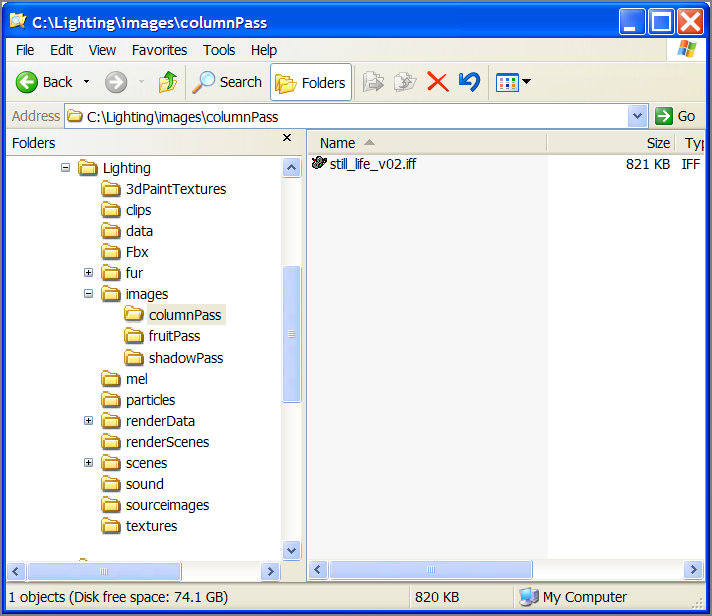
When you batch render, your image files are written to the Images folder of the current project. Make sure your project is properly set; otherwise, your files will end up in an unexpected folder. You can always see the render path and the image name at the top of the Render Settings window, as shown in Figure 11-26.
Figure 11-26: The Render Settings window shows you where the images will be rendered.

Rendering the Wine Bottle
In this section, you’ll set up and render an animated camera to move over 25 frames of a wine bottle still life.
Set your current project to the Lighting project downloaded from the book’s web page, and then load still_life_render_v01.mb. You’ll adjust your render settings and some shader properties to make the wine bottle look more like glass.
Selecting Render Settings Options
Set your resolution and quality settings in the Render Settings window.
Setting Up the Scene
Now, set up some of the objects in the scene. The wine bottle has been imported into the still life scene, and three wine glasses have been added. All the lights are in place, as is the camera.
Start by setting up this scene to raytrace to get true reflections and refractions.
Figure 11-27: Shadow lights
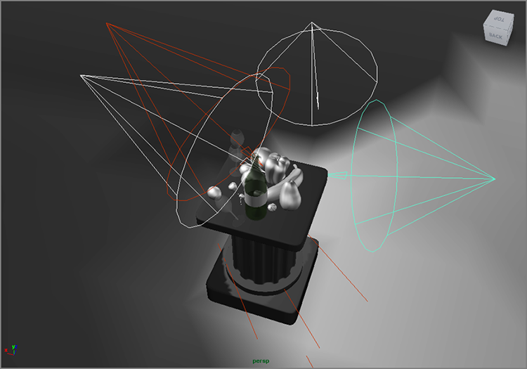
Setting Up the Camera
Next, you’ll set up the camera to render the scene.
Figure 11-28: The camera view at the beginning of the animation
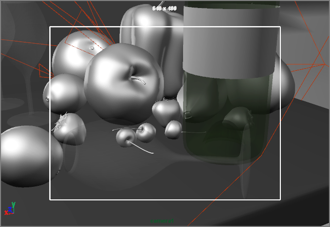
Figure 11-29: Pull out the camera.
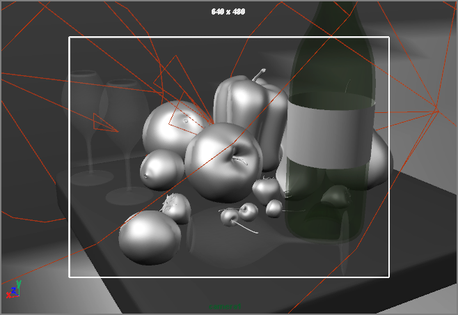
Scrub your animation, and you’ll see a pullout revealing the full scene.
Batch Rendering and Playing Back the Sequence
Now, you’re ready to render out the 25-frame sequence. Choose Render ⇒ Batch Render.
Because you’re raytracing this scene at full resolution, this render could take 20 minutes or longer. To chart the progress of the render, open the Script Editor by clicking its icon on the Help line or by choosing Window ⇒ General Editors ⇒ Script Editor.
To see the frames play back, you’ll need a program that can load the images in sequence and play them back for you. You can also import the image sequence into a compositing or editing program, such as Adobe After Effects or Premiere, to play back as a clip and edit as you like.
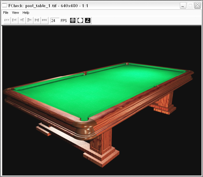
You can also use FCheck, a frame viewer that is included with Maya. This small and surprisingly powerful program plays back your images in real time so that you can judge your finished animation. To use FCheck, follow these steps:
Figure 11-30: FCheck, shown here with a sample image, plays back your rendered sequence.
mental ray for Maya
You had some experience with mental ray rendering in the previous chapter as you lighted using Physical Sun and Sky, which automatically used Final Gather to render. In this part of the chapter, I’ll discuss mental ray options to begin to scratch the surface of this incredibly powerful renderer.
First, if you haven’t done so already, be sure that mental ray is loaded. When you first start up, mental ray for Maya may not load because it’s considered a plug-in. Choose Window ⇒ Settings/Preferences ⇒ Plug-in Manager to open the Plug-in Manager, shown in Figure 11-31. Make sure both the Loaded and Auto Load check boxes for Mayatomr.mll (or Mayatomr.bundle for Mac users) are checked so that mental ray for Maya loads by default.
Figure 11-31: Use the Plug-in Manager to load mental ray for Maya.

To render with mental ray, open the Render Settings window, and change the Render Using drop-down menu selection to mental ray, as shown in Figure 11-32 (shown with the Features tab selected). The Render Settings window now has the Common tab along with five other mental ray–specific tabs: Passes, Features, Quality, Indirect Lighting, and Options.
Figure 11-32: The Render Settings window for mental ray, showing the Features tab

mental ray Quality Settings
As with the Maya Software renderer, the primary quality settings for the mental ray renderer center on anti-aliasing. However, mental ray for Maya offers you finer control over how you set the quality levels through the Render Settings window. Under the Anti-Aliasing Quality ⇒ Raytrace/Scanline Quality heading on the Quality tab, you’ll find these attributes:
For those who are already familiar with previous mental ray workflows, Legacy Sampling Mode will give you access to additional sampling modes available in previous versions of mental ray for Maya. Legacy Sampling is discussed in the “Legacy Sampling” sidebar. However, Unified Sampling mode attempts to greatly simplify the quality settings for mental ray for Maya and is preferred for use.
The Error Cutoff value (default at 0) and check boxes for Contrast as Color (default at off) are used for more advanced tweaking of quality settings and by and large should be left at their defaults.
Sample Lock is turned on to reduce noise and artifacts in rendered sequences that have lots of movement.
Rather than setting high sample rates with just the Min and Max Sample Level attributes, carefully increase the Quality value to force mental ray to use a sample rate closer to the Max Samples only where it needs to do so. You’ll see this in action in the next section.
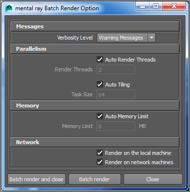
When you’re ready to render your scene to disk, you still use batch rendering; however, the options in the Batch Render Option window are different (Figure 11-33) than they are for Maya Software.
Figure 11-33: mental ray batch render options
Render Settings in Action!
In this section, you’ll look at how Quality values and how the number of Min and Max Samples work together to determine the quality of the render of a toy wagon. You can find the scene (RedWagonRenderSettings.ma) to render in the RedWagon project on the book’s web page. Make sure to set your project to RedWagon. This scene is set up to use Final Gather with an IBL using an HDR image. I’ll cover these methods later in this chapter.
Open the Render Settings window, making sure you are set to mental ray, and open the Quality tab. Set your Sampling Mode value to Unified Sampling. Occasionally you may see that Sampling Mode reverts to Legacy Sampling Mode when you open a file even though it was set to Unified Sampling. If that is the case, any settings you’ve created for Unified Sampling Mode do remain intact. Unified Sampling is mental ray’s newest method to speed up rendering, replacing what is now called Legacy Sampling Mode. Quality should be set to 0.50, Min Samples to 1.0, and Max Samples to 1.0 in this file already.
These render quality settings are low at first and will yield the render shown in Figure 11-34, which took just less than two minutes. You can see jagged highlights on the wagon, especially the white lines on the side body, the reflections in the front black nose, and the edge of the white rims on the back wheel.
Figure 11-34: A toy wagon rendered with low sampling values. Notice the jagged highlights on the white decal lines and the back wheel.

If you increase Max Samples Level to 100 and Min Samples Level to 1.0, you’ll see an immediate increase in quality (especially in the reflections of the wagon and the white decal lines) and a noticeable increase in render time (about 50 percent as long), as shown in Figure 11-35, which took just under three minutes to render.
Figure 11-35: Better sampling improves the wagon’s appearance.

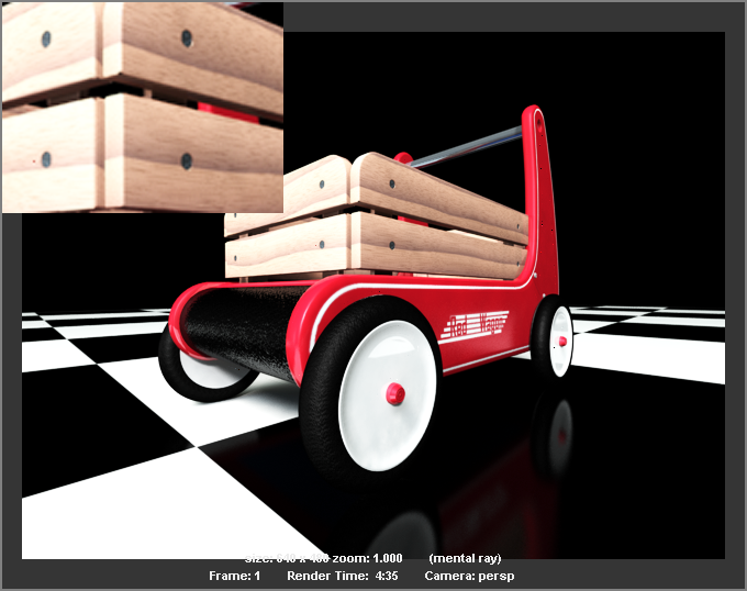
You can get an even cleaner render. If you crank up the Quality value to the heavens, such as 2.0, you get a far cleaner render than before but with a much longer render time. Figure 11-36 shows the same frame with the Quality value set to 2.0 instead of the default of 0.5. The Min Sample Level option is still set to 1, and the Max Sample Level option is left at 100. The wood panels and the reflections of the wagon in the checkered floor are both noticeably nicer in this render. Your results as you render the scene on your own computer will be more noticeable than the images shown here. But this render took 4:35.
Figure 11-36: The wagon has still better sampling with a higher Quality value. You’ll see it better in your own renders.
For very quick render to check composition and lighting, set your Quality, Min, and Max Samples all to 0.1. You should get a super-fast render, though good luck discerning much detail. It’s easy enough to crank the numbers to the sky, but render times will very quickly become unacceptable, especially when you have a supervisor or client breathing down your neck. Find just the right combination of numbers for acceptable results in a minimum of time. Each scene will be different.
Motion Blur with mental ray
Now that you have a primer on quality settings in mental ray for Maya, you’ll learn how motion blur works.
Figure 11-37: The Solar_System project is back!

Figure 11-38: A render of frame 75 shows the planets in motion without any motion blur.

Figure 11-39: Turn on motion blur.

Figure 11-40: Render a frame with motion blur turned on.
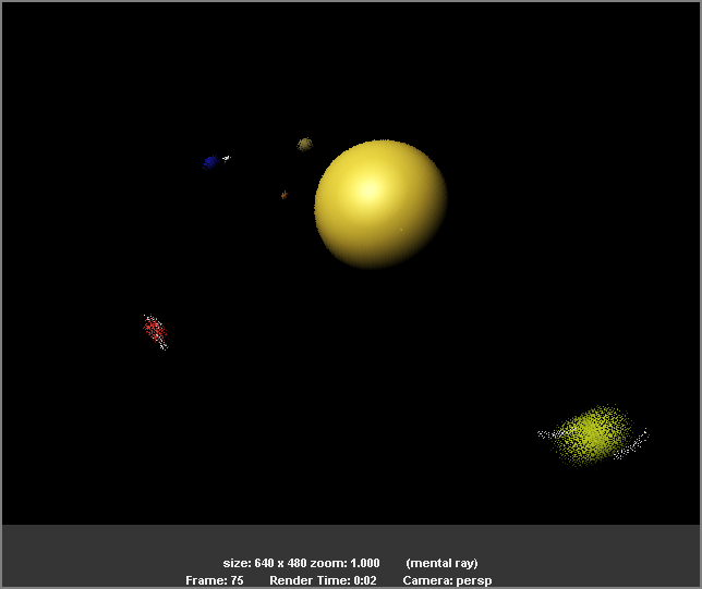
Figure 11-41: Motion blur looks much better with higher sampling levels.

Render Layers
Most of the time, it’s better to composite different elements together to form a final CG image. Professional CG workflow almost always requires multiple render passes that are composited together later for the maximum in efficiency and quality.
Maya does a great job of making rendering in layers much easier with render layers. As you saw earlier in this book, using display layers helps a lot in keeping your scene organized. Render layers operate in basically the same way, although they function by separating different elements of the scene into separate renders.
I’ll address the most basic and commonly utilized render layer functionality here: separating objects into different renders. You’ll select elements in a scene and assign them to different render layers. When you batch-render the scene, Maya will render each of the layers separately and save the files into their own subfolders in the Images folder of your current project. You’ll then need to load all the different rendered layers into a compositing program, such as The Foundry’s NUKE or Adobe After Effects, and composite the layers together.
Render Passes in mental ray
Two powerful features in mental ray rendering, Render Passes and Pass Contribution Maps, make rendering in passes and elements much more efficient. Passes allow you to separate shadows, reflections, diffuse color, and so on, from the render to give the most control in compositing over the image. This mental ray–specific workflow is fairly advanced and requires an existing knowledge of rendering and compositing render passes (such as you will do with render layers) to fully grasp. Thus, I won’t cover these features in this book; however, you should be aware of this mental ray rendering pipeline as you move beyond this introduction and continue rendering with mental ray in your own work.
Rendering the Still Life in Layers
In this example, you’ll separate a scene into different layers for rendering with mental ray, though the render layer workflow here applies to Maya Software rendering as well.
To separate a scene into different layers, follow these steps:
Figure 11-42: The newly created render layer with the foreground lemon assigned

Figure 11-43: Rename the render layer to lemonPass.

Figure 11-44: Add the lights to the lemonPass render layer.
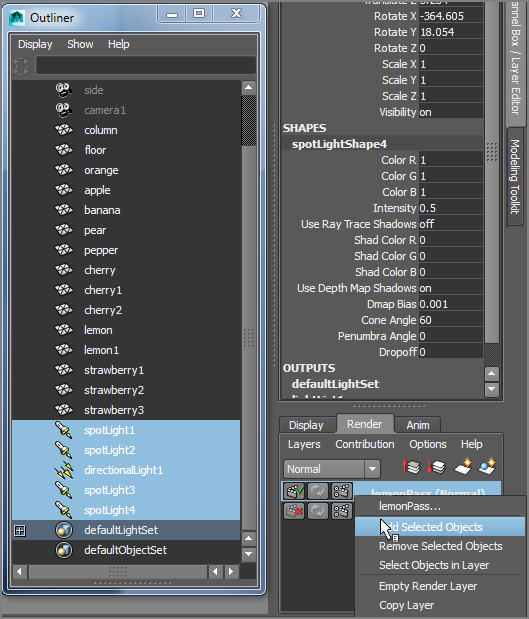
Figure 11-45: The lemon rendered on its very own layer

Figure 11-46: The background is assigned to its own render layer.

Figure 11-47: The newly created fruitPass render layer

Figure 11-48: Rendering the rest of the fruit

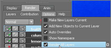
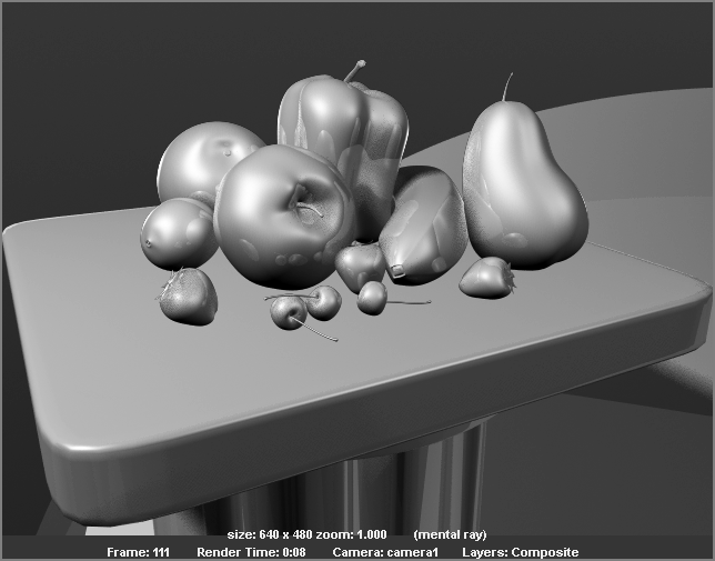
Test-Rendering Everything Together
By default, Maya renders only the selected visible render layer. You can, however, tell Maya to test-render and show you all the layers composited together to give you a preview of what you’ll end up with when you composite all the layers together after batch-rendering the scene.
To test-render all the layers together, click the Options menu in the Layer Editor, as shown in Figure 11-49, and toggle on Render All Layers by clicking the check box if it isn’t already selected.
Figure 11-49: Turn on Render All Layers.
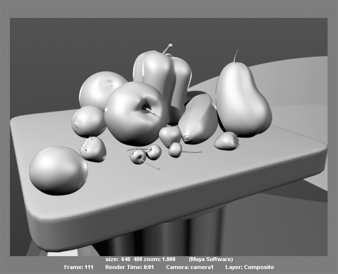
Now if you test-render a frame, Maya will render each layer separately and then composite them together. Test-render a frame with Render All Layers enabled, and you should notice that the foreground lemon is missing, as in Figure 11-50.
Figure 11-50: Rendering all the layers together
This is because the render layers in the Layer Editor need to be reordered so that columnPass is on the bottom, fruitPass is in the middle, and lemonPass is on top. This is the layer ordering for the composite. You can reorder the render layers by MMB+clicking a layer and dragging it up or down to its new location in the Layer Editor, as in Figure 11-51.
Figure 11-51: Reorder the render layers.

Now if you render the frame with Render All Layers enabled, you see the scene properly placed, as shown in Figure 11-52. Notice that shadows and reflections on the column’s tabletop are missing, however. For that, you will need to create render layer overrides to allow reflections and shadows of an object to render, but without the object itself rendering.
Figure 11-52: Now the lemon appears in the render.
Render Layer Overrides
Where are the shadows and reflections? If you recall from earlier in this chapter, this scene renders with shadows, and this scene should have reflections as well. However, the reflections and shadow-casting objects are on different layers than the column. Shadows and reflections can’t be cast from one layer onto another. In the following steps, you’ll use render layer overrides to set up your columnPass layer to have shadows and reflections from the fruit but not render the fruit on top of the column:
Figure 11-53: Add the fruit back into the layer.

Figure 11-54: Turn off Primary Visibility to set a render layer override for the orange on the columnPass layer.

Figure 11-55: The column is rendering with shadows and reflections.

Figure 11-56: The shadows are crisp and clean but too sharp.

Figure 11-57: The layers all rendered together with soft shadows and reflections

You can check your work against the file still_life_renderLayers_v02.mb from the Scenes folder of the Lighting project on the book’s web page.
Batch Rendering with Render Layers
Now that you have everything separated into render layers, let’s talk about batch-rendering the scene to composite later. Make the render layers you want to render renderable by making sure the Renderable icon next to each render layer is enabled, as shown in Figure 11-58.
Figure 11-58: Check to make sure the layers you want to render are enabled.

In the Render Settings window, make sure Renderable Camera is set to camera1, as shown in Figure 11-59. Select your image file type and anything else you need to set in the Render Settings window. Then, in the main Maya window, choose Render ⇒ Batch Render to render the scene. Because render layers are enabled here, Maya renders the scene into different subfolders under the Images folder of your current project. Each render layer gets its own folder in the Images folder, as shown in Figure 11-60.
Figure 11-59: Select camera1 as your renderable camera in the Render Settings window.

Figure 11-60: Render layers batch-render into subfolders in the Images folder of your project.
I have only begun to scratch the surface here. When you get the hang of rendering and as your CG needs begin to grow, you’ll find a plethora of options when rendering with layers and rendering with passes through mental ray. This section and the “Ambient Occlusion” section later in this chapter are here only to familiarize you with the basic workflow of render layers. You can find a wealth of information about rendering in layers and passes in the Maya online documentation under the Help menu.
Final Gather
Final Gather (FG) is a type of rendering with mental ray that includes a simple light bounce within the scene. Final Gather traces light as it reflects off surfaces to illuminate the scene for a nicely realistic render that takes into account color bleed of light from one surface to another. For example, a red wall casts a red hue on the surface right next to it. FG is an intricate dance of settings and numbers that lets you get perfect renders. It’s tough to cover in an introductory book such as this; however, this section will give you a primer to start using FG. In a follow-up section, you’ll use a combination of lights and HDRI with Final Gather to render the decorative box.
The basic premise is that FG uses the illumination in the scene from lights as well as objects with color and incandescence set in their shaders to create a soft natural light. Its base settings will give you nice results right from the start.
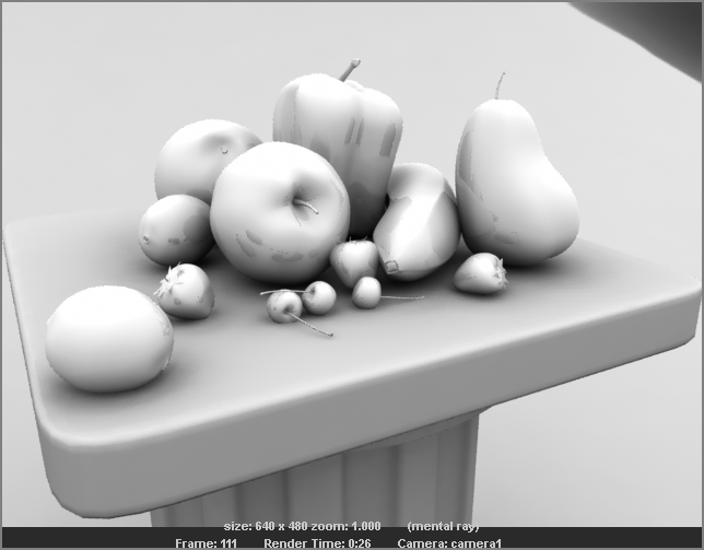
To render the still life fruit scene with FG, begin by creating a dome light, which evenly illuminates a scene from a dome around the scene. (The term dome light is a bit of a misnomer, because a dome light isn’t itself a light.) You’ll construct a simple NURBS sphere, cut it in half to create a dome, and give it an Incandescent shader to provide the light for the scene. This type of quick FG setup is extremely useful for rendering out soft lighting and shadows to show off a model or a composition.
To light and render with FG, follow these steps:
Figure 11-61: Create a sphere to act as a light dome.
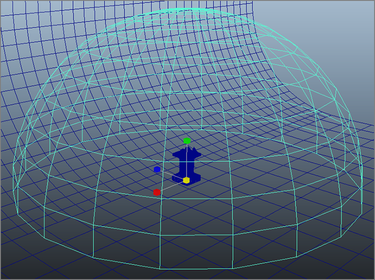
Figure 11-62: The Quality tab

Figure 11-63: The Indirect Lighting tab accesses all the Final Gather settings.
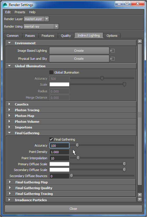
Figure 11-64: The Final Gather render of the still life

You can adjust the level of lighting by increasing or decreasing the amount of incandescence on the light dome’s shader. The proximity of the sphere also affects the light amount, so moving the sphere closer or farther away will change the lighting level as well. You can also insert lights into the scene as you see fit.
You can improve the quality of the render by adjusting any of the following three settings in the Indirect Lighting tab under the Final Gathering section of the Render Settings window:
Figure 11-65: Accuracy set at 500 increases the smoothness of the soft shadows. It’s hard to see here, but you’ll notice it in your own render.
The Point Density and Point Interpolation attributes, along with several other attributes under the Final Gathering section, optimize and further control the FG settings for optimum efficiency and results, especially with animated scenes. Consider using the basic settings shown in this chapter to become familiar with mental ray for Maya, and then use FG to crank out fast and elegant renders to show off your models until you get more comfortable with mental ray.
Final Gather is a tough nut to crack; it will take you some time to become proficient at rendering with FG in scene files and especially with animated scenes. Later in this chapter, you’ll try your hand at using FG, HDRI, and regular lights to render the decorative box from the previous chapters.
Ambient Occlusion
Ambient Occlusion is a special render pass that helps add depth and reality to a render. Ambient Occlusion goes by the premise that when two objects or surfaces are close to each other, they reduce the amount of light at the intersection. Ambient Occlusion passes make for great contact shadows and bring out the definition in surface creases and corners very nicely. Figure 11-66 shows an Ambient Occlusion pass for the living room scene from the PDF Global Illumination exercise included on the book’s web page.
Figure 11-66: The Ambient Occlusion pass is black and white and is used to darken areas of the original color render.

How the composite works is very simple. Ambient Occlusion gives you a black-and-white pass of the same geometry you’ve already rendered. This pass is then multiplied over the color render. That means a brightness value of white (a value of 1) in the Ambient Occlusion pass won’t change the color of the original render (when the original color of the render is multiplied by 1, it stays the same color). The black parts of the frame (with a brightness value of 0) turn those parts of the original render black (when the original color of the render is multiplied by 0, it goes to black). The gray points of the multiplying image darken the original render. It sounds confusing, but when you see it, it makes much better sense.
The Living Room
You’ll now take the living-room render made in the PDF file exercise on the web page and add an Ambient Occlusion pass using render layers. You don’t have to read the PDF exercise to understand the concepts and practices for making an Ambient Occlusion pass here. However, if you’d like to understand how to light the living-room scene with Global Illumination, you may want to read that exercise on the web page now and then return to the following.
Set your current project to the Livingroom project you copied from the web page, open the livingRoom_v2.mb file from the Scenes folder, and follow these steps:
Figure 11-67: Select the scene objects for your Ambient Occlusion pass.
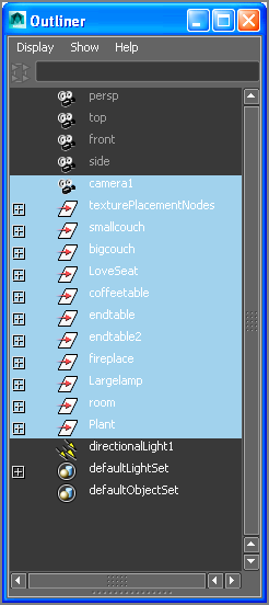
Figure 11-68: Create a new render layer.

Figure 11-69: Setting an Occlusion preset for the layer
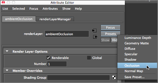
Figure 11-70: The Ambient Occlusion shader in the Hypershade

Figure 11-71: The first render from the Ambient Occlusion pass doesn’t look great—it’s too dark.

Figure 11-72: The Ambient Occlusion shader attributes

Figure 11-73: Set Max Distance to 4.

Figure 11-74: The Ambient Occlusion layer pass looks much better, but you aren’t finished yet!

Figure 11-75: The Outliner view of the glass geometry in the scene

Figure 11-76: The Ambient Occlusion pass

Rendering the Results
You could save the image you just rendered in the Render View window to use in the composite and then render the masterLayer for the color pass in the Render View and save that frame as well. Instead, let’s batch-render the scene to show how Maya handles rendering with layers enabled. To batch-render the scene, follow these steps:
Figure 11-77: Maya renders the layers into their own folders by default.

If for some reason your renders don’t show up in your project’s Images folder, open the Script Editor window and look at the batch-render report. The render feedback shows you where the rendered images were saved, as shown in Figure 11-78. You may also want to make sure you set your project to the Livingroom project from the web page.
Figure 11-78: The Script Editor gives you feedback on the progress of the batch render.

Compositing the Results
Now that the two layers are rendered in their respective folders, load them into your favorite compositing package. You’ll layer the Ambient Occlusion pass over the color render using a Multiply Transfer mode. This exercise uses Adobe After Effects CS4 to demonstrate how the Ambient Occlusion pass is composited over the original color render.
Figure 11-79 shows After Effects with the masterLayer color pass loaded. Figure 11-80 shows the ambientOcclusion pass layered on top of the color layer. Finally, Figure 11-81 shows the ambientOcclusion pass changed to a Multiply Transfer mode (as it’s called in After Effects). Notice how the dark areas of the Ambient Occlusion pass help give contact shadows and depth to the color pass. Voilà!
Figure 11-79: The masterLayer render pass is loaded into After Effects.

Figure 11-80: The ambientOcclusion render pass is loaded into After Effects.
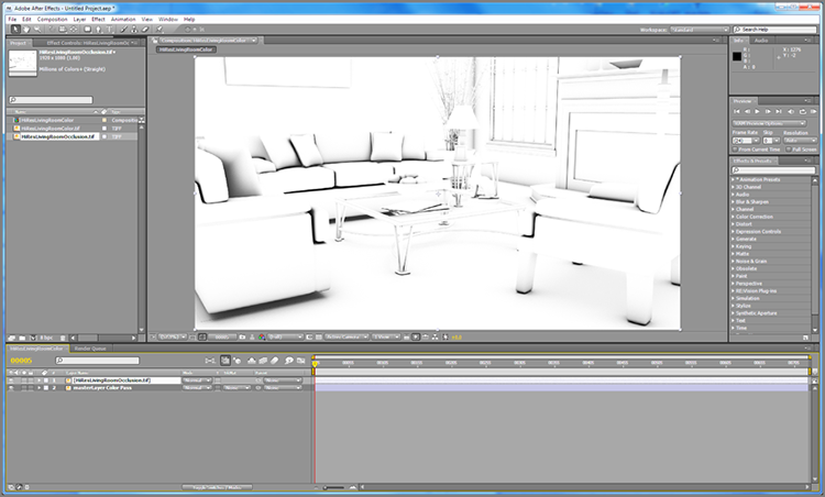
Figure 11-81: The ambientOcclusion pass is multiplied over the color pass and creates a more realistic image.

This is a prime example of rendering different passes to achieve a more realistic result. Use different layers to put your final images together in composite.
You can see the difference Ambient Occlusion made to the living-room image in the Color Section of this book and on the web page.
HDRI
As you saw in the Final Gather section, FG rendering is based on the illumination in the scene from lights as well as the brightness of objects in the scene, such as a light dome. In a previous section, you used an incandescent dome to light the still-life scene. But what if you were to use an image instead of just white for the light dome?
Furthermore, what if the image you used was a high dynamic range image (HDRI)? In Chapter 1, I briefly discussed HDR images. Several photos at varying exposures are taken of the same subject, ranging from very dark (low exposure), to highlight only the brightest parts of the scene, and going all the way up to very bright (overexposure), to capture the absolute darkest parts of the scene. When these images (usually five or seven images) are compiled into an HDR image, you get a fantastic range of bright to dark for that one subject.
How does this help you light? With image-based lighting (IBL), mental ray creates an environment sphere in your scene to which you assign an image, usually an HDRI. That environment sphere, much like the white dome in the Final Gather exercise earlier in the chapter, uses the brightness of its image to cast light in your Maya scene.
The best type of image to capture for an IBL is sometimes called a light probe. This is a picture of an environment, such as the office reflected in a chrome ball shown on the left of Figure 11-82 or the stitched-together panoramic stills compiled into a map shown on the right of Figure 11-82. The stitched panoramic on the right of Figure 11-82 was photographed at four 90-degree angles using a fish-eye camera lens capable of capturing a field of view of close to 180 degrees using a panoramic tripod attachment.
Figure 11-82: A light-probe photo of a desk is taken with a chrome ball (left) and a panoramic stitch (right).
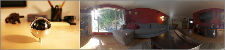
Figure 11-82 shows the middle exposure of five exposures taken of the office and one of the four angles of the living room. Figure 11-83 shows five images in the range from underexposed (dark) to overexposed (bright) photos that were used to compile the HDRIs shown here. You will use an HDRI made from the living-room panoramic photos to light the decorative box in the next section.
Figure 11-83: Five exposures make up the HDRI of a desk using a chrome ball (left); and a living room using a panoramic stitch (right), which is to be used in the next section

The living-room photos are taken at 90-degree intervals inside the living room and then stitched and compiled in an HDRI file using a photographic software package (shown in Figure 11-84). The HDRI file is called livingRoomPanoramic.hdr and is in the Sourceimages folder of the TableLamp project on the web page for the next section’s IBL lighting exercise. You won’t be able to see the extensive range of the HDR, because the great majority of computer displays are limited to a display of 8-bit color.
Figure 11-84: Fish-eye photos are taken at four angles of the living room, each with several exposures from light to dark (above). The fish-eye photos are then warped and stitched together using the very handy software package PTGui and merged into an HDR image file (bottom).

The HDR will be mapped onto an IBL sphere. This is a large sphere that surrounds the environment in your Maya scene. The individual photos first need to be stitched together and converted to a rectangular image file, as shown in Figure 11-84. The full spherical panorama space captured in these photos and stitched together is laid out into a rectangular format that is suitable to project onto a sphere in Maya, just as if a geographic map on a school room globe was unwrapped into a rectangular sheet of paper.
Software such as HDRShop, available online for free, allows you to combine multiple images into an HDR. One useful program, PTGui from the Netherlands (available for a demo online at http://ptgui.com), allows you to stitch panoramas as well as merge HDR images, which makes it a fantastic tool for CG lighters and photographers. As long as the photos to be stitched were taken with enough overlap at the edges, PTGui is able to turn them into a large panoramic photo. And if the proper exposure ranges were also taken, PTGui creates a solid HDR as well. I won’t get into the details of creating the HDRI, because it’s an advanced topic using Photoshop CS5, PTGui, and/or other software; however, it’s good to know the origins of HDR images and how they come to be used in IBL.
Displacement Mapping the Decorative Box
Before continuing with the lighting and rendering for the lamp and decorative box, let’s first address a need for detailing just the box by itself. Look at the photo of the box in Chapter 3, “The Autodesk Maya 2014 Interface.” (Figure 3-24) and compare it to the close-up renders of the box in Chapter 10 (Figure 10-68); you’ll see that the carved details in the CG box need more detail. Let’s start by taking a closer look at the box by itself.
Figure 11-85: Oh no! Reference file not found!

Figure 11-86: The lamp and decorative box’s current render when you finished the lighting in Chapter 10

In the current render, the grooves are flat and shiny, whereas in the real box, they’re carved into the wood and aren’t glossy like the rest of the box. You will add definition to the model through textures next.
You can use the scene file lampLighting_v02 to catch up to this point or compare your camera angles.
Reflection Map
Just as you use a map to put color on the box, you can use similar maps to specify where and how much the box will reflect. Figure 11-87 shows the color map you used to texture the box in Chapter 7 side-by-side with a black-and-white map that shows only the carved regions of the box. This map was created with elbow grease and hard work to manually isolate just the carved areas of the box in Photoshop. See how much I do for you?
Figure 11-87: The black-and-white map on the right shows only the carved areas of the box.
You’ll first take the reflections out of the carved areas in the following steps:
Figure 11-88: Create a new file node.

Figure 11-89: Select the proper image file.

Figure 11-90: The swatch shows a thumbnail of the image you’re using.

Figure 11-91: Map the new image file to the Reflectivity attribute.

Figure 11-92: The reflections are stronger; the entire box looks like a mirror.

Figure 11-93: The carvings don’t reflect, but the rest of the box’s reflections are still too strong.

Figure 11-94: Set Alpha Gain to 0.4.

Figure 11-95: The reflections look much better now.

You can open the scene file boxDetail03.ma from the Scenes folder in the Decorative_Box project to catch up to this point or to check your work so far.
Displacement Mapping
Now that the reflections are set up, you’ll use the same image map to create displacements in the box to sink the carvings into the box. Isn’t that convenient?
Figure 11-96: Add the new image map to the Displacement Map attribute.

Figure 11-97: The shader network for the box

Figure 11-98: The displacements seem to be wrong!

Figure 11-99: Set the attributes for the displacement image.

Figure 11-100: The carvings are displacing outward.

Figure 11-101: The carvings are inset into the wood, but they don’t look good yet.

Figure 11-102: The current box’s mesh isn’t detailed enough.

Figure 11-103: Set the Add Divisions values.
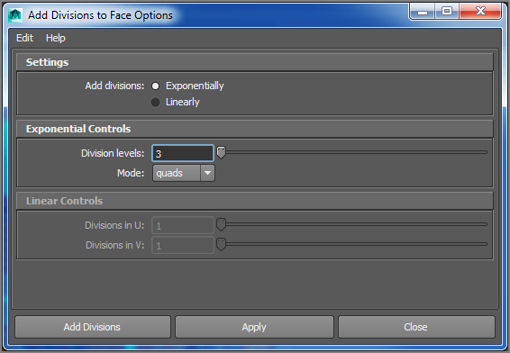
Figure 11-104: Added divisions
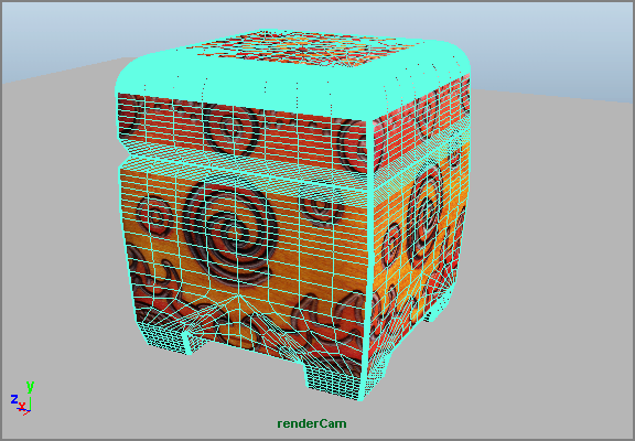
Figure 11-105: The displacements render much better now.

Compare your work to the scene file boxDetail05.ma in the Scenes folder of the Decorative_Box project.
Notice that the render times increased because you increased the detail on the mesh in step 8. This increase is normal, but it can become a problem if the mesh is too divided and has more faces than you need. This box has fairly detailed carvings, so the level to which you set Add Divisions in step 8 gives a good result without being too detailed. As your experience increases in Maya and mental ray rendering, you’ll learn how to use functions such as the mental ray Approximation Editor to keep the overall detail low on the mesh but with smooth displacement results when you render. This is an advanced technique, so I won’t cover it in this book. You’ve taken in quite a lot by this point already.
The next time you select the box and open the Attribute Editor, you’ll see a new tab called polySubdFace1. This is the node added with the Add Divisions function in step 8. Feel free to adjust the Subdivision Levels setting on that tab and render to see how the detail levels affect the final render. Also try better quality settings in Render Settings, as you did with the red wagon earlier in this chapter, to clean up the render to your satisfaction.
You’ll next add an IBL sphere and use the HDR image you saw earlier in the chapter.
Rendering the Lamp and Decorative Box
You’re all grown up and ready to light a full scene using Final Gather, IBL with HDRI, and regular lights to get the best bang for your buck out of mental ray rendering. In the previous chapter, you briefly lit the lamp and decorative box with key, fill, and rim lights (the three-point lighting system). In this exercise, you’ll take this concept a few steps further, so take a deep breath, call your mother and tell her you love her, and let’s get started!
Set your project to the TableLamp. Open the lampLighting02.ma file in the Scenes folder. This scene has the lights and soft shadows created in Chapter 10 and is set to render through mental ray with raytracing enabled already. Let’s take a critical look at the render from the previous chapter in the earlier Figure 11-86.
Now that you have created a more detailed box, let’s update the reference in this scene. Choose File ⇒ Reference Editor. You are currently reading in boxDetail01.mb. Click boxDetail01.mb to select the entry, and choose Reference ⇒ Replace Reference. Navigate to the Decorative_Box project’s scene folder, and select boxDetail05.mb.
All your work detailing the box will now pop into the lamp lighting scene. Render a frame from the persp camera view. Figure 11-106 shows a comparison of the render from before the added detail (left) and the newly detailed box in the lamp lighting scene (right). The detailed box looks much nicer now, although you have to tweak the render quality settings in this scene later.
Figure 11-106: The render on the right shows all the added detail to the box missing from the render on the left.

Adding an IBL
Here’s where things get fun. You’ll add an IBL node to the scene and add the living-room HDR image to that IBL. First make sure you have mental ray selected as your renderer in the Render Settings window, and then follow along with these steps:
Figure 11-107: Click to create an IBL.

Figure 11-108: The Attribute Editor for the IBL node

Figure 11-109: The IBL is in place and mapped to the office chrome ball HDRI.

Figure 11-110: Rotate the IBL sphere in the Y-axis to 155.

Figure 11-111: Enter a value of 3 to increase the brightness of the HDRI.

Figure 11-112: It’s a noisy and bright render.

Fixing Final Gather Noise
The render from the previous section looks nice, except that it’s noisy. Notice the blotches of light all over the floor. This is from having low-quality settings for FG. On the Render Settings’ Indirect Lighting tab, increase Accuracy to 500 under the Final Gathering heading and Point Interpolation to 50. Doing so dramatically increases the render time for the frame (almost doubling the previous time); however, it makes the scene look much better—practically eradicating the blotchy nature of the previous renders. The floor plane is still a bit blotchy, but you’ll take care of it soon. The lamp and box have a nice glossy look to them thanks to the reflections and soft light from the HDRI. (See Figure 11-113.) Save the image to your Render View buffer.
Figure 11-113: Using higher-quality settings for FG makes a big difference.

You can open the scene file lampLighting03.ma from the Scenes folder in the TableLamp project to catch up to this point or to check your work so far.
FG is a difficult beast to tame, especially with an IBL. It takes a lot of experience and practice to be able to use this powerful feature of mental ray successfully in scenes. Experiment with different HDR images that you can download from the Internet as well as adjusting the lights in the scene.
Blurring Reflections with the mia_material
Let’s tweak the render a little more by making a new tabletop floor plane for the lamp and box to sit on to make the table look like a rich brown wood. You will use the mental ray mia_material shader:
Figure 11-114: Create a mia_material shader.
Figure 11-115: Create walls and a wood tabletop.

Figure 11-116: Not a bad render

Let’s Get a Little Closer
Now that you have an overall look, let’s create a new camera and get closer to the subjects.
Figure 11-117: Create and frame the new camera for a close-up shot.

Figure 11-118: Render the close-up shot.

Figure 11-119: Create a blurred reflection for the blue shader.

Figure 11-120: Softened reflections create a nicer, more realistic look to the render.
Also try rendering the wider view in the other camera (RenderCam) and see how you can adjust lighting and shader settings for that angle.
Save your work, and compare it to the lampLighting_v04.mb scene file found in the Scenes folder of the TableLamp project from the companion web page. And if you decide to batch-render this scene, make sure to select one of the two cameras you created for this scene in the Render Settings window.
Adding Depth of Field
One last item of interest is adding a depth of field (DOF) to the image. This effect adds blur to the render for the areas of the image that may be out of the lens’s focal depth. It can greatly add to the photo-realism of a rendered image.
Select the closeUpCam, and open the Attribute Editor. In the Depth Of Field heading, check the Depth Of Field attribute. Set Focus Distance to 14, and set F Stop to 11. The F Stop setting, like a real lens, sets how much is in focus around the focal distance. With a higher F Stop value, the focus runs deeper than with a low F Stop value.
Figure 11-121 shows the final render of the lamp and box with DOF enabled. Your render times will be longer, and for a better render, you’ll need to increase your Sample settings. Figure 11-121 was rendered with Min Samples of 0, Max Samples of 1, and Anti-Aliasing Contrast of 0.04 and took several minutes to complete.
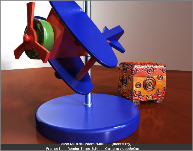
Figure 11-121: The decorative box is in focus! We’re finished!
The scene file lampLighting_v04.ma from the Scenes folder in the TableLamp project will take you to this point.
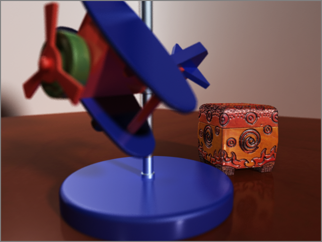
Notice from the render that the biplane is thrown out of focus, along with the back of the tabletop and the walls. Experiment with varying focus distance and F Stop values to try different looks for your scene. For example, keep the biplane in focus, but throw the box out of focus.
Depending on the need and the size of the render, you’ll have to set the sampling levels to suit your needs—but be warned that your rendering times will dramatically increase, easily tripling depending on the quality settings. There are several ways to create DOF in a render that are faster or more controllable than what I’ve covered here. You can render out a depth pass to use with a lens filter in a compositing package such as Nuke to keep render times down. There are also more accurate DOF methods in mental ray and its lens shaders that you can experiment with when you’ve comfortably grasped the overall workflow presented here.
Try also experimenting with the different sampling modes to see whether you can shave time off the render. The table lamp scenes are all set to legacy sampling settings, so setting it to a Unified Sampling Mode may get you faster results. Finally, adding an Ambient Occlusion pass isn’t absolutely necessary for this render, although it may enhance the look of the contact shadows.
Wrapping Up the Lamp and Decorative Box
When you’ve learned a lot more about lighting and gained confidence with the processes of lighting, rendering, and compositing, you’ll find a wealth of options when you render in several different layers. For example, if this lamp and decorative box scene were a professional job, its render would most likely be split into a flat color pass, a reflection pass, a specular highlight pass, a shadow pass, an Ambient Occlusion pass, a depth pass, and several different matte passes that separate parts of the scene to give the compositor the ultimate control in adjusting the image to taste.
You may not know what all those passes do right now, but understanding will come with time as long as you continue practicing your CG Kung Fu. Rendering your own color passes and Ambient Occlusions will give you some beautiful renders even without all the other passes. Keep in mind that small changes and additions can take you a long way toward a truly rich image.
Summary
In this chapter, you learned how to set up your scene for rendering. Starting with the Render Settings window and moving on to the different render engines available, you learned how to render your scene for a particular look. Then, I covered how to preview your render and how to use IPR for fast scene feedback. I moved on to how to render reflections and refractions, how to create and use cameras, and how to render motion blur. You tested your skill on a wine bottle scene, and to batch-render it out into a sequence of images, you checked it in a program like FCheck. You also used Maya render layers, overrides, and rendering an Ambient Occlusion pass to make your renders more realistic. Finally, you applied this knowledge to rendering the lamp and the decorative box using Final Gather and an HDR of a living room.
Getting to this point in a scene can take some work, but when you see the results playing back on your screen, all the work seems more than worth it. Always allow enough time to ensure that your animations render properly and at their best quality. Most beginners seriously underestimate the time needed to complete this step properly in CG production.
After you create numerous scenes and render them, you’ll begin to understand how to construct your next scenes so that they render better and faster. Be sure to keep on top of your file management—rendering can produce an awful lot of files, and you don’t want to have them scattered all over the place.