
Chapter 9
More Animation!
Now that you have a little more animation experience, you can get into some more involved animation practices and toolsets, taking further the principles covered in this book and its examples. Animation is a growing exploration, and you should use this book as a stepping-off point. For everything you’re being exposed to here, there are many more techniques to discover.
- Use hierarchies to your advantage in animation tasks
- Create and manipulate a skeleton system for animation
- Group model pieces to a skeleton
- Create a walk cycle using forward kinematics for pose animation
- Copy and paste keyframes to extend animation
- Discern the three different ways—rigid, smooth, interactive—to bind a mesh to a skeleton in Maya
- Use inverse kinematics in a rig of a simple character
- Create a walk cycle using IK animation
- Use constraints to automate animation
- Create set-driven keys for animation rigging
- Rig a locomotive for automated animation
- Rig a simple character for basic character animation
Skeletons and Kinematics
If you don’t have a skeleton, you probably aren’t reading this book. In your body, your muscles move the bones of your skeleton, and as your bones move, parts of your body move.
In CG animation, a skeleton is an armature built into a 3D model that drives the geometry when the bones are moved. You insert a skeleton into a CG model and attach or bind it to the geometry. The skeleton’s bones are animated, which in turn move the parts of the geometry to which they’re attached. By using a skeleton, the Autodesk® Maya® software allows bending and deformation of the attached geometry at the skeleton’s joints. A skeleton is useful for character work, but skeletons have many other uses. Any time you need to drive the geometry of a model with an internal system, such as a fly-fishing line or a tree bending in the wind, you can use skeletons. You’ll use them to drive the locomotive wheels and a simple character later in this chapter.
Skeletons and Hierarchy
Skeletons rely on hierarchies (see Figure 9-1). Bones are created in a hierarchical manner, resulting in a root joint that is the parent of all the joints beneath it in the hierarchy. For example, a hip joint can be the root joint of a leg skeleton system in which the knee joint is the leg’s child, the ankle joint belongs to the knee, and the five toe joints are the ankle’s children.
Figure 9-1: A leg skeleton and its hierarchy

Geometry need not deform to be attached to a bone system; objects can be grouped with or under joints. They move under their parent joint and rotate around that joint’s pivot as opposed to their own pivot point.
A skeleton is really just a collection of grouped and properly positioned pivot points called joints that you use to move your geometry, whether it deforms or not. A bone is the length between each joint; bones only show you the skeletal system.
Inverse kinematics (IK) and forward kinematics (FK) are the methods you use to animate a skeletal system. FK rotates the bones directly at their top joint to assume poses. This method resembles stop-motion animation, in which a puppet, along with its underlying armature, is posed frame by frame. With FK, the animator moves the character into position by rotating the joints that run the geometry.
The rotation of a joint affects the position of the bones and joints beneath it in the hierarchy (see Figure 9-2). If you rotate the hip up, the knee and ankle swing up as if the character is kicking.
Figure 9-2: In forward kinematics, the joints are rotated directly.

IK uses a more complex, but often easier, system of IK handles that are attached to the tip of a joint system. The corresponding base of the IK system is attached farther up the skeleton hierarchy to a joint determined to be the root of that IK segment. It need not be the root joint of the entire skeleton, though.
The bones and joints in the IK chain are affected only by movement of the IK handle. When the handle moves, an IK solver figures out how to rotate all the joints to accommodate the new position of the IK handle. Moving an IK handle causes the bones to rotate around their joints to accommodate a new position.
The effect is as if someone grabbed your hand and moved it. The person holding your hand is similar to an IK handle. Moving your hand causes the bones in your arm to rotate around the shoulder, elbow, and wrist. As you can see in Figure 9-3, the animation flows up the hierarchy and is therefore called inverse kinematics.
Figure 9-3: In inverse kinematics, the joints rotate in response to the IK handle’s position.

Forward Kinematics: The Block Man
To understand skeletal hierarchy, look at Figure 9-4, which shows a simple biped (two-legged) character made of primitive blocks. He’s called the BlockMan. (Surprise!) Each block represents part of the body, with gaps between the blocks representing points where the body pivots.
Figure 9-4: The Block Man’s cubes arranged

The pivot of each block is placed to represent the appropriate joint location. For example, the shin’s pivot is located at the knee. Each block is grouped up the chain so that the foot moves with the shin, which moves with the thigh, which moves with the pelvis.
The hands are grouped under the arms, which are grouped under the shoulders, and so forth, down the spine to the pelvis. The head groups under the first neck block and so on down the spine to the pelvis. The pelvis is the center of the body, which is known as the root of the figure.
The way this figure is grouped (see Figure 9-5) represents how the hierarchy of a character works for the most part. Each body part is attached and becomes the child of the part above it in the chain.
Figure 9-5: Pivot placements and grouping

Load the file block_man_v02.mb from the Block_Man project folder on the book’s web page, www.sybex.com/go/introducingmaya2014, for a good reference of the grouping structure. This file shows you what a skeleton hierarchy does.
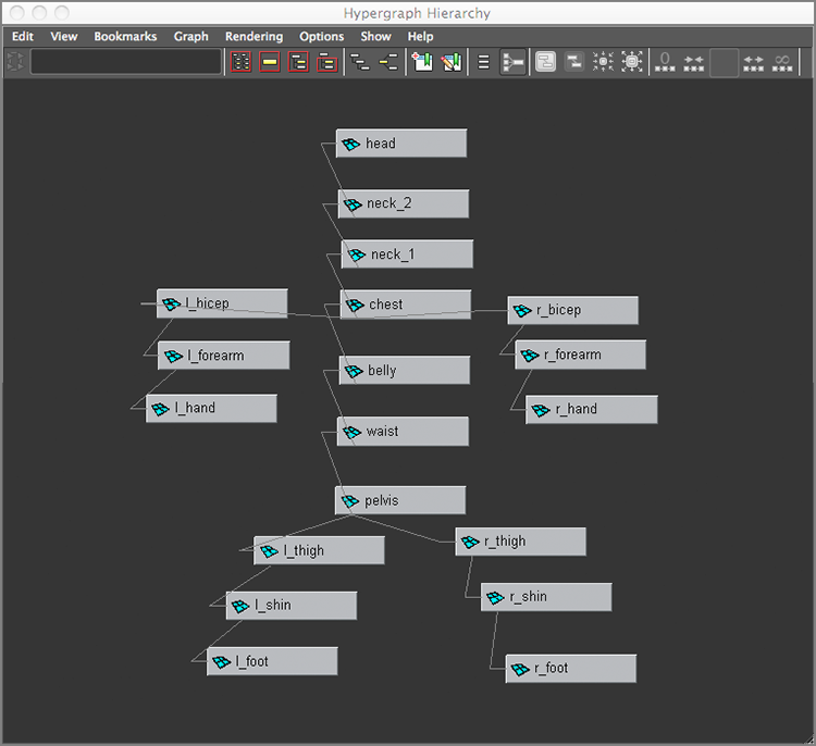
In the Hypergraph Hierarchy window, choose Options ⇒ Layout ⇒ Freeform Layout to position the nodes any way you want. To make selections easier, you can arrange the nodes as if they were on a body (see Figure 9-6). You can toggle between freeform and automatic, and your freeform layout will be retained.
Figure 9-6: A freeform layout in the Hypergraph Hierarchy window
Creating the Skeleton
The basis of how the Block Man is laid out and grouped is what skeletons are all about. Skeletons make character animation easier by automating, at the very least, the hierarchy and pivot placement described earlier.
You’ll use the Block Man to create a simple skeleton. Load block_man_v01.mb from the Block_Man project. This is the same as block_man_v02.mb, but this version isn’t grouped.
Figure 9-7: Place spine joints straight up the middle of the body, and offset the last joint in the head.

Figure 9-8: Place joints for the arm.

Figure 9-9: Group the lt_clavicle to the chest.
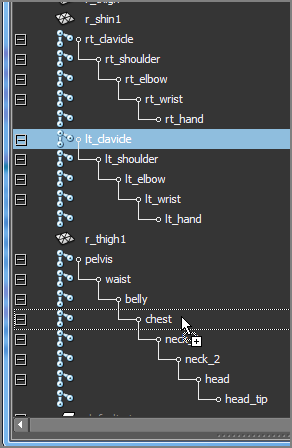
Figure 9-10: The arms are grouped to the chest, and the joints are connected with new bones.

Figure 9-11: Place the leg joints and name them.

Figure 9-12: Duplicate the leg joints, move them to the other leg, and name the new joints (left). The skeleton is complete (right).

You’re all done! You’ll be adding to this later in the chapter as you create a more well-rounded rig for the character, but for now, check your work against Figure 9-12 (right) and the block_man_skeleton_v01.mb file from the Block_Man project.
Attaching to the Skeleton
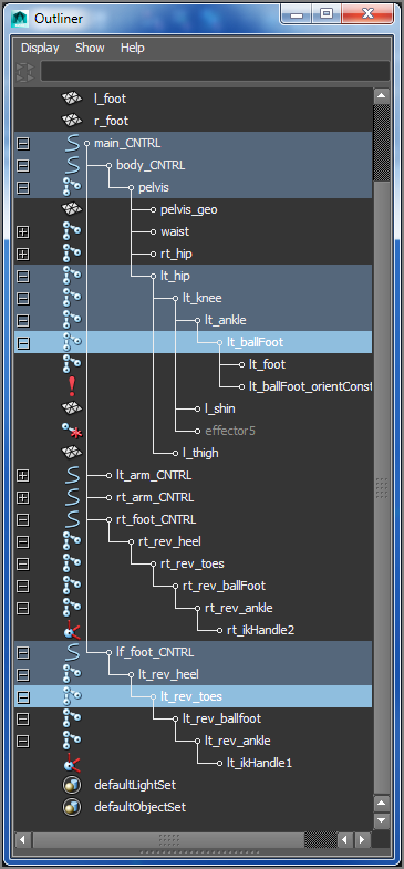
You now have a full skeleton for your character. To attach the geometry, all you need to do is parent the body parts under their appropriate joints. Before you get to that, take a few minutes and make sure all your joints are named in the Outliner to make the scene easier to manage. You can use Figure 9-13 as a naming reference.
Figure 9-13: After you check your naming, you’ll parent the pelvis geometry under the pelvis joint.

You can also load the block_man_skeleton_v01.mb file from the Block_Man project to get to this point.
To parent the Block Man’s geometry to the skeleton, follow these steps:
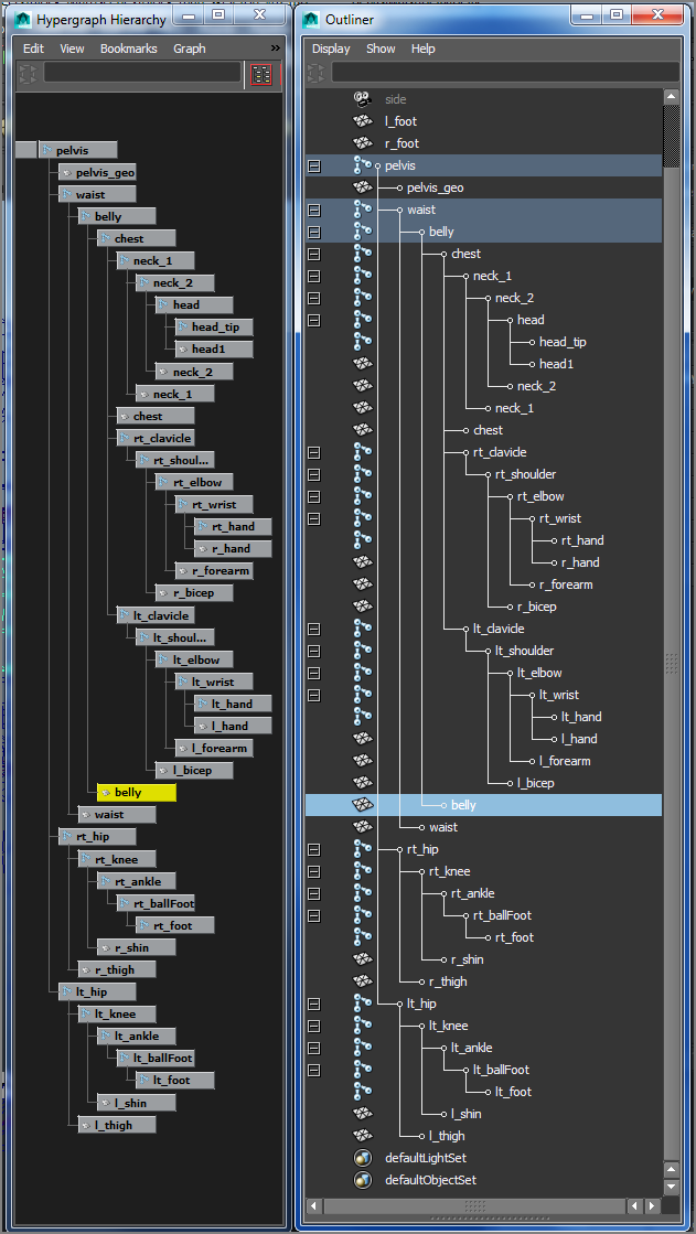
Figure 9-14: Parent all the geometry except the feet into its proper place in the skeleton. The finished hierarchy is shown in the Hypergraph and Outliner side-by-side.
- Shins under the knees and thighs under the hips
- Hands under the wrists and forearms under the elbows
- Biceps under the shoulder joints
- Head under the head joint (not the head_tip joint)
- Top neck geometry (neck_2) under neck_2 joint
- Bottom neck geometry (neck_1) under the neck_1 joint
- Chest under the chest joint
- Belly under the belly joint
- Waist under the waist joint
Figure 9-15: The Rigid Bind Skin Options: the left foot geometry and the left foot joints selected (left). Bind and test the left foot (right).

The Block Man is now set up with a skeleton that you’ll use to make a simple walk cycle. This exercise will help get you more familiar and comfortable with animating a character. You will do more to this setup to make a better animation rig for the Block Man character later in the chapter.
The Block Man: FK Walk Cycle
A walk cycle is an animation that takes the character through a few steps that can be repeated many times so that the character seems to be taking numerous steps. In a cycle, make sure the position of the first frame matches the position of the last frame so that when the animation sequence is cycled, no “pop” occurs in the motion at that point.
Now, try animating this character’s walk cycle using FK on the skeleton. You’ll find the workflow straightforward, as if you were adjusting positions on a doll.
Load the block_man_skeleton_v02.mb file from the Block_Man project from the companion web page for the properly grouped and bound model and skeleton. In addition, the right arm and leg have drawing overrides enabled in this file to make their wireframe display white to make it easier to distinguish between the right and left sides while working.
Use the key poses in the following figures to guide you in animating the body as it walks. You’ll key at five-frame intervals to lay down the gross animation. You can go back and adjust the timing of the joint rotations in the Graph Editor to make the animation better later. The white leg and arm are behind the body, farther from the camera.
This animation is also called pose animation because you’re posing the character from keyframe to keyframe.
Starting Out: Frames 1 and 5
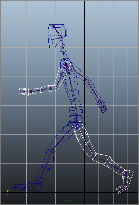
Figure 9-16 shows the character’s starting position. Here, you’ll set a key for this position and then begin the walk cycle by moving the joints into their second position and keyframing that.
Figure 9-16: The character’s starting position

Figure 9-17: The second pose (frame 5)

If you don’t key everything every step of the way, some parts of the body won’t key with Auto Keyframe properly because the last time they moved may have been two steps previous. This may cause confusion, so it’s best to key every joint at every step until you feel more comfortable editing character animation.
Frame 10
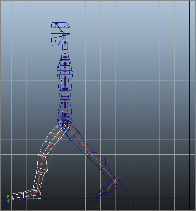
Figure 9-18 shows the position you’ll keyframe at frame 10; it’s approximately midstride for the first leg.
Figure 9-18: The third pose (frame 10)
Frame 15
Figure 9-19 shows the position you’ll keyframe at frame 15. At this point, the character begins to shift his weight to the front leg as it plants on the ground, and the character also begins lifting the back leg.
Figure 9-19: The fourth pose (frame 15)

Frame 20
At frame 20, the man will shift all his weight onto the front leg and move his body over that leg, lifting his rear leg to begin its swing out front to finish the stride. Figure 9-20 shows the pose. Follow these steps:
Figure 9-20: The fourth pose (frame 20)

Frame 25
Now, the man will swing his whole body forward, pivoting on the left leg (the dark one) to put himself off center and ready to fall forward into the next step. Figure 9-21 shows the pose. Here are the steps:
Figure 9-21: The sixth pose (frame 25)

Frame 30
Use Figure 9-22 as a guide for creating the next pose. Notice that it’s similar to the pose at frame 10. As a matter of fact, the only major differences are which leg and arm are in front. Everything else should be about the same. You’ll want some variety in the exact positions to make the animation more interesting, but the poses are very similar.
Figure 9-22: The seventh pose (frame 30)

Completing the First Steps
You’ve finished a set of poses for the character’s first step. The next set of poses for your walk cycle corresponds to the first set, but now the other leg and arm correspond to these positions. For example, you animated the left leg taking a step forward in the first series of poses. The next series of poses has to do with the right leg. The pose at frame 35 corresponds to the pose at frame 15. Frame 40 matches frame 20. You will copy keyframes in the Graph Editor to make more steps, but first, let’s retime these initial keys before continuing.
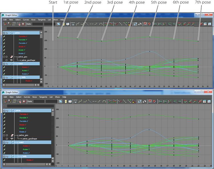
When a 30-frame section is complete, you need to return to the animation through the Graph Editor. Adjust all the keyframes that you initially set at these five-frame intervals to make the animation more realistic. Right now, you have only the gross keyframes in place, so the timing is off. Timing the frames properly is ultimately a matter of how the animation looks to you.
Logistically speaking, some poses take a little less time to achieve than the evenly spaced five frames you used. For example, achieving the second pose from the start position should take four frames. The third pose (see Figure 9-18, earlier in the chapter) from frame 5 to frame 10 should take four frames. The next frame section, originally from frame 10 to 15 (the fourth pose; see Figure 9-19, earlier in the chapter), should take only three frames. To accomplish this easily, follow these steps:
Figure 9-23: The Graph Editor shows the walk animation curves (top). The curves are retimed (bottom).
Load the file block_walk_v01.mov or block_walk_v01.avi of this walk cycle from the Images folder of the Block_Man project from the companion web page to see the animation in motion. It’s a rough cycle, and you have to keep adjusting the character’s height to keep the feet on the ground. This is where IK comes in handy, as you’ll see later in this chapter. Also, the file block_man_skeleton_walk_v01.mb in the Block_Man project has the keyframed steps for you to play with and continue animating.
Copy and Paste Keyframes
Now that you have a base to work with, you’ll copy and paste keyframes to extend the animation further. This can get a little tricky, so take this slow if you’re not comfortable with the Graph Editor yet. Open the file block_man_skeleton_walk_v01.mb to follow along with these steps:
Figure 9-24: Copy and paste keys for the white colored leg.

Figure 9-25: Copy and paste keys for the body movement.

Open the file block_man_skeleton_walk_v02.mb from the Block_Man project to check your work to this point.
Walk Cycle Wrap-Up
This walk cycle animation is more about getting comfortable with keyframing and skeletons than it is about creating great walk animation, so take some time to practice and get better. Character animation takes a lot of time and patience, and I encourage you to keep tweaking this animation and even create different walks of your own. Animating walk cycles is a good way to hone your skills. Several great books are devoted to character rigging and animation alone, and you can research the field for ways to become more proficient. But keep in mind that movement and timing are what make animation good, not the setup or the model.
Skeletons: The Hand
For another foray into a skeletal system, you can give yourself a hand—literally. You’ll use a skeleton to deform the geometry and animate it as a hand would move.
Load the file poly_hand_skeleton_v01.ma from the Poly_Hand_Anim project from the companion web page. The hand is shown in Figure 9-26 (top).
Figure 9-26: The hand mesh (top); placing joints in the hand (bottom)

You’ll use it to create a bone structure to make the hand animate. This process is called rigging.
Rigging the Hand
To create the first bones of the hand, follow these steps:
Figure 9-27: The joints in the hand

Check the other views (see Figure 9-28) to see where you need to tweak your joint positions to fit the hand. Ideally, you want the joints to be set inside your intended geometry in the same way that real bones are laid out.
Figure 9-28: Four views of the hand with initial placement of the joints
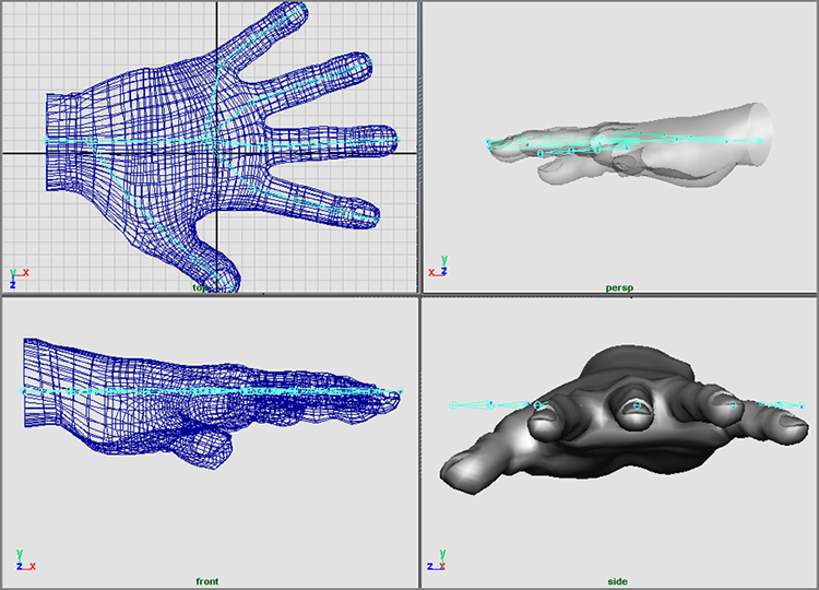
To position the joints, you can use either of two Maya tools: Move or Move Pivot. First, you’ll try the Move tool. Select the tip joint for the pinkie. It needs to be lowered into the pinkie itself. Select the Move tool (press W), and move it down into the tip of the pinkie. Now, move on to the top pinkie knuckle. Notice that if you move the knuckle, the tip moves as well. That’s not such a great idea.
Instead, it’s best to move joints as pivots. Because joints are nothing more than pivots, go into Move Pivot mode (hold down the D key to activate Move Pivot, or press the Ins key on Windows or the fn+Home key on a Mac) to move joints. Select the top pinkie-knuckle joint, and move it with Move Pivot instead. Only the joint moves, and the bones adjust to the new position. Set the positions on the remaining joints to be inside the hand properly, as shown in Figure 9-29 and Figure 9-30.
Figure 9-29: The joints of the hand placed properly in the geometry

Figure 9-30: Second view of the hand’s skeleton

Binding to Geometry
An integral part of rigging a character or an object with a skeleton is binding, also known as skinning. Binding is another way to attach geometry to a skeletal system. With the Block Man, you directly attached the whole pieces of geometry to the bones through parenting, whereas binding involves attaching clusters, or groups of vertices or CVs, of the geometry to the skeleton to allow the skeleton to deform the model. This is typically how skeletons are used in character animation work. (For more on grouping and parenting, refer to the solar system exercise in Chapter 2, “Jumping in Headfirst, with Both Feet.”)
The basic technique of binding a character is easy. However, Maya gives you tremendous control over how your geometry deforms.
Binding Overview
Binding is, in theory, identical to the Lattice deformer you saw in Chapter 5, “Modeling with NURBS Surfaces and Deformers.” A lattice attached to an object exerts influence over parts of the model according to the sections of the lattice. Each section affects a NURBS surface’s CVs or a polygon surface’s vertices within its borders—and as a section of the lattice moves, it takes those points of the model with it.
Skeletal binding does much the same thing. It attaches the model’s points to the bones, and as the bones pivot around their joints, the section of the model that is attached follows.
By attaching vertices or CVs (depending on your geometry) to a skeleton, you can bend or distort the geometry. When a bone moves or rotates about its joint, it pulls with it the points that are attached to it. The geometry then deforms to fit the new configuration of the bones bound to it.
You can directly bind geometry to a skeleton in three ways: using Smooth Bind, Interactive Skin Bind, and Rigid Bind. You can indirectly deform geometry using deformers and lattices attached to skeletons, but here you’ll use the direct methods. Figure 9-31 shows a rigid bind, and Figure 9-32 shows a smooth bind. Note that an interactive skin bind will yield similar results to the smooth bind.
Figure 9-31: Rigid bind of a cylinder. The crease is pronounced.

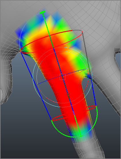
Figure 9-32: Smooth bind of the cylinder. The crease is smoother yet less defined. You may expect this result from the interactive skin bind as well.
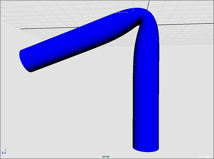
Create a tall NURBS cylinder, with a span of 16 or more. The more spans you have in the deformable model, the better it will bend. Duplicate the cylinder, and move it over in your window. Now, in the front view, create a four-bone (five-joint) skeleton that starts at the bottom of the first cylinder and goes straight up the middle, ending at the tip. Duplicate the skeleton, and move it to the center of the second cylinder.
Creating a Rigid Bind
A rigid bind is the simpler of the two because only one surface point (vertex or CV) is affected by a joint at a time. A rigid bindgroups the CVs of a NURBS or the vertices of a polygon into joint clusters that are then attached to the bones. No one surface point is influenced by more than one joint. You created a rigid bind for the Block Man’s feet earlier in the chapter.
Bending a model around a joint with a rigid bind yields a more articulate crease than a smooth bind. A smooth bind allows more than one joint to affect the CV or vertex, resulting in a more rounded and smooth bend.
To create a rigid bind, select the first skeleton and Shift+click its cylinder. In the Animation menu set, choose Skin ⇒ Bind Skin ⇒ Rigid Bind ![]() .
.
In the option box, you’ll find that almost everything you need is already set to the default. The BindTo parameter lets you rigid-bind the entire skeleton to the geometry or rigid-bind only the joints selected. Using Selected Joints gives you the option of using just part of a skeleton system to rigid-bind, which also gives you flexibility in how your rig affects the model. Leave that option set to Complete Skeleton to attach the whole thing.
Click the Color Joints check box to set a different color for each joint in the bind, which can make for an easier workflow. The Bind Method parameter deals with how the points in the model are attached. The default, Closest Point, organizes the points into skin point sets according to the joint to which they’re closest. They’re then assigned to be influenced by that joint only.
The Partition Set option lets you define your own points before you bind and select which points are set to which joints. If you define a partition set for each joint you have, Maya assigns each set to the nearest joint. For example, you can define some points at the top of the surface to be part of a set controlled by a joint in the bottom part. Closest Point is the best option for most work.
Use the defaults, turn on Color Joints, and click the Bind Skin button in the option box. The root of the skeleton is selected, and the cylinder turns magenta, signifying that it has input connections (such as history).
Creating a Smooth Bind
A smooth bind allows a joint to influence more than one skin point on the model. This lets areas of the model farther from the joint bend when that joint rotates. Joints influence points to varying degrees between 0 and 1 across the surface, decreasing in influence the farther the point is from the joint. The multiple influences on a point need to add up to 1 across all the joints that influence it. Maya automatically generates the proper influence amounts upon binding, although the animator can change these values later.
To create a smooth bind, select the second skeleton and its cylinder, and choose Skin ⇒ Bind Skin ⇒ Smooth Bind ![]() .
.
In the option box, you’ll find the familiar Bind To parameter. You’ll also find, under the Bind Method drop-down menu, the options Closest In Hierarchy, Heat Map, and Closest Distance. Choosing Closest In Hierarchy assigns the skin points to the nearest joint in the hierarchy. This option is most commonly used for character work, because it pays attention to the way the skeleton is laid out. For example, a surface point on the right leg wouldn’t be affected by the thigh joint on the left leg simply because it’s near it on the model. Closest Distance, on the other hand, disregards a joint’s position in the hierarchy of the skeleton and assigns influences according to how far the point is from the joint. The Heat Map method uses a “heat diffusion” technique to create influence falloff radiating out from the joint.
Max Influences sets a limit on how many joints can affect a single point. Dropoff Rate determines how a joint’s influence diminishes on points farther from it. For example, with Smooth Bind, one shoulder joint can influence, to varying degrees, points stretching down the arm and into the chest and belly. By limiting these two parameters, you can control how much of your model is pulled along by a particular joint.
Using all the defaults is typically best. So, click Bind Skin in the option box to smooth-bind your second cylinder to the bones.
Bend both cylinders to get a feel for how each creases at the bending joints. Figure 9-33 shows the difference.
Figure 9-33: Rigid- and smooth-bound cylinders. The smaller cylinder is rigid bound, and the larger is smooth bound.

Interactive Skin Bind is practically the same as Smooth Bind and yields similar results to the smooth binding shown in Figure 9-33, but the editing of the influences is slightly different than for Smooth Bind. You will explore Interactive Skin Bind with the hand model later in this chapter.
Detaching a Skeleton
If you want to do away with your binding, select the skeleton and its geometry, and choose Skin ⇒ Detach Skin. The model will snap to the shape it had before the bind was applied and the joints were rotated. It’s common to bind and detach skeletons several times on the same model as you try to figure out the exact configuration that works best for you and your animation.
If you need to go back to the initial position of the skeleton at the point of binding it to the model, you can automatically set the skeleton back to the bind poseafter any rotations have been applied to any of its joints. Simply select the skeleton and choose Skin ⇒ Go To Bind Pose to snap the skeleton and model into the position they were when you bound them together. It’s also best to set your skeleton to the bind pose whenever you edit your binding weights.
Binding the Hand: Rigid
Because you want definitive creases at the finger joints, you’ll use Rigid Bind for the hand.
Load your hand and positioned skeleton, or use the file poly_hand_skeleton_v02.ma from the Poly_Hand_Anim project from the companion web page. Now, follow these steps to rigid-bind the hand:
Figure 9-34: Select the root joint as well as the top node of the hand.
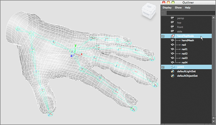
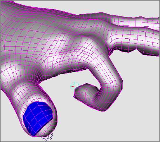
Figure 9-35: The crease at the knuckle is severe, and the geometry folds over into itself.

Editing a Rigid Bind
Having a rigid bind doesn’t mean your creases always have to be this hard. With flexors (basically lattices, as discussed in Chapter 5), you can smooth out specific areas of a joint for a better look. This is useful at shoulder joints or hip joints, where a crease such as on an elbow isn’t desired. In this case, it will help smooth out the knuckles so the geometry doesn’t fold over itself, as in Figure 9-35.
Figure 9-36: Creating a flexor
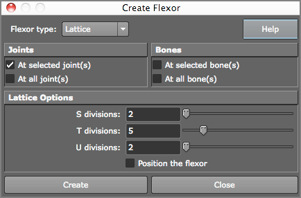
Figure 9-37: Creating a flexor at the middle knuckle

Figure 9-38: Scaling the flexor to fit better on the knuckle

Figure 9-39: The knuckle’s crease is now sharp, but the geometry doesn’t fold over itself as before.
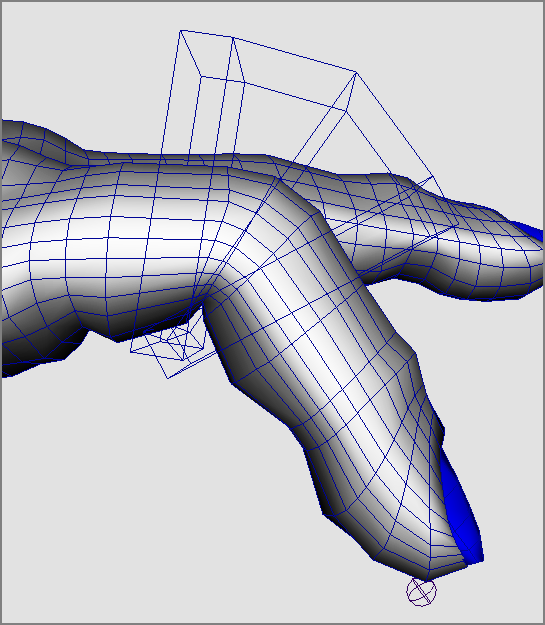
Figure 9-40: Flexors along the index finger

For reference, the scene poly_hand_skeleton_v03.ma from the Poly_Hand_Anim project on the companion web page has the hand rigid-bound with flexors on one finger. Start with it to create flexors for the rest of the fingers and animate the hand, making some sign language positions, grabbing a pencil, or pressing a button.
Binding the Hand: Smooth
Now, try skinning the hand with Smooth Bind.
Load your prebound hand or poly_hand_skeleton_v02.ma file from the Poly_Hand_Anim project from the web page. Now, follow these steps to smooth-bind the hand:
Figure 9-41: Bending at the index finger causes some unwanted deformation.

Editing a Smooth Bind
You usually edit a smooth bind by painting skin weights. Because points on the model are influenced by multiple joints in a smooth bind, you need to adjust just how much influence is exerted by these joints on the same points.
Figure 9-42: The option box for the Paint Skin Weights tool
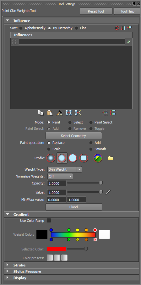
Figure 9-43: Paint the new weights to avoid unwanted deformations in the hand.

You can exit the Paint Skin Weights tool by selecting another tool (press W for Translate, for example), and your view will return to regular Shaded mode. Try bending the rest of the fingers and painting their influences; then, animate the hand, making gestures or grabbing an object using FK animation to set keys on the rotations.
The scene poly_hand_skeleton_v04.ma from the Poly_Hand_Anim project from the companion web page has the hand smooth-bound with painted weights on the index finger for your reference. Try painting the other knuckles as needed for your animation.
Binding the Hand: Interactive Skin Bind
Now, try skinning the hand with Interactive Skin Bind.
Load your own prebound hand or poly_hand_skeleton_v02.ma file from the Poly_Hand_Anim project from the web page.
The Interactive Skin Bind method is a bit easier to control when compared to the painting of the Smooth Bind weights. However, one limitation of Interactive Skin Bind compared to Smooth Bind is that it recognizes only a single mesh to be bound to the skeleton. In other words, you cannot bind the current hand as it is, since the fingernails are separate objects. But that is easy enough to fix.
Figure 9-44: The volume manipulator shows the influence of the selected joint.

Figure 9-45: The index finger’s first knuckle influences the middle finger, too.
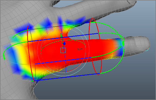
Figure 9-46: Use the volume manipulator to reduce the influence on the middle finger.

Figure 9-47: Set the influences by adjusting the volume manipulator.
Editing the interactive skin bind, as you can see, is very easy using the volume manipulators. If you exited the tool when you first created the bind and no longer see the volume manipulators, you can access them by choosing Skin ⇒ Edit Smooth Skin ⇒ Interactive Skin Bind Tool. When you access this tool, the volume manipulators appear again, and you’re able to adjust your skin’s influences.
When you are happy with the proper level of influence, keep picking the other joints in the index finger to make sure your binding is proper. Then continue to the other fingers to set up the binding on the hand properly. This is definitely easier than painting weights as before, though not as controllable. Test the bind by bending the joints. You can compare your work to the prebound hand found in the poly_hand_interactiveBind_v01.ma scene file in the Poly_Hand_Anim project.
Inverse Kinematics
With IK, you have tools that let you plant a foot where it needs to be so you’re not always moving the skeleton or model to compensate and keep the heel in place.
For legs, IK is nothing short of a blessing. There is no clearly preferable workflow to suggest when dealing with rigging arms and hands, however. Many people use IK on hands as well, but it can be better to animate the legs with IK and animate every other part of the body with FK. IK is best used when parts of the body (such as the feet) need to be planted at times. Planting the hands isn’t necessary for a walk cycle, and having IK handles on the arms may create additional work while you are animating them. You will create a more well-rounded character rig that uses IK and easy-to-use character controls at the end of the chapter. First, let’s get familiar with how IK works.
Rigging IK Legs
Back to the Block Man. Switch to that project, and load your version or the block_man_skeleton_v02.mb file from the Block_Man project from the companion web page.
You’ll create an IK chain from the hip to the ankle on each foot. Creating the IK from the hip to the toe won’t work.
Because IK automatically bends the joints in its chain according to where its end effector, or IK handle, is located, it has to choose which way to bend at a particular joint. This is why you created the legs slightly bent in the Block Man rig earlier in the chapter.
If you did not do this or your setup has straight legs for whatever reason, select the two knee joints, and in Pivot mode (hold down the D key), move the knees forward a bit over the feet to create a slight crook in the legs. Don’t go too far; a slight amount is enough. This lets the IK solver know which way those joints are supposed to go.
Now, on to creating the IK:
Figure 9-48: IK handles on both ankles with the roots at the hip joints
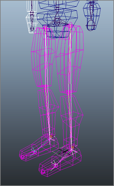
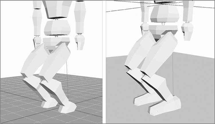
Figure 9-49: Creating another IK chain from the ankle to the tip of the foot and setting keyframes makes the feet stay on the ground (right) and not rotate into the ground (left).
Creating an IK Walk Animation
Because the Block Man’s feet will stick to the ground, creating a walk cycle with IK animation is far easier than using FK (why didn’t you tell us that before?). Making the animation look good is still a tough job that requires a lot of practice, though.
Load the scene file block_man_IK_v01.mb from the Block_Man project from the companion web page, or use your own IK-rigged Block Man with handles at the ankles and feet. The white leg and arm are, again, on the far side of the character. You’ll set keys every five frames again for the gross animation. To keep this short, I’ll just discuss setting poses with the feet. You can always return to the scene to add animation to the upper body with FK, as you did earlier in this chapter. Follow these steps:
Figure 9-50: Step 3’s pose (frame 5)
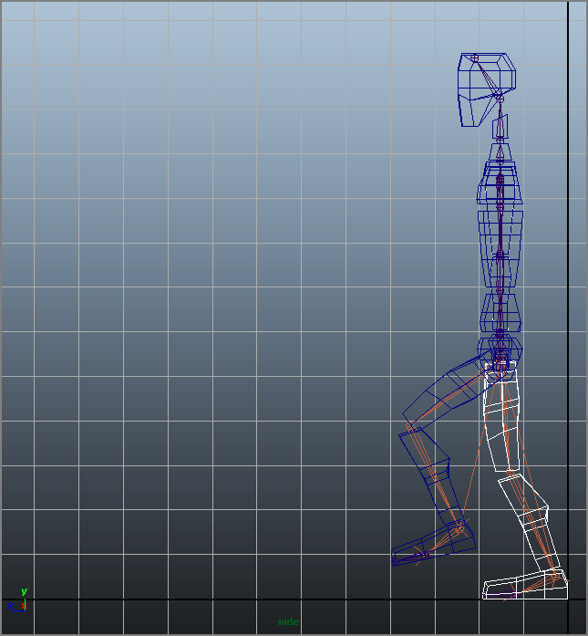
Figure 9-51: Step 4’s pose (frame 10)

Figure 9-52: Step 5’s pose (frame 15)

Figure 9-53: Step 6’s pose (frame 20)
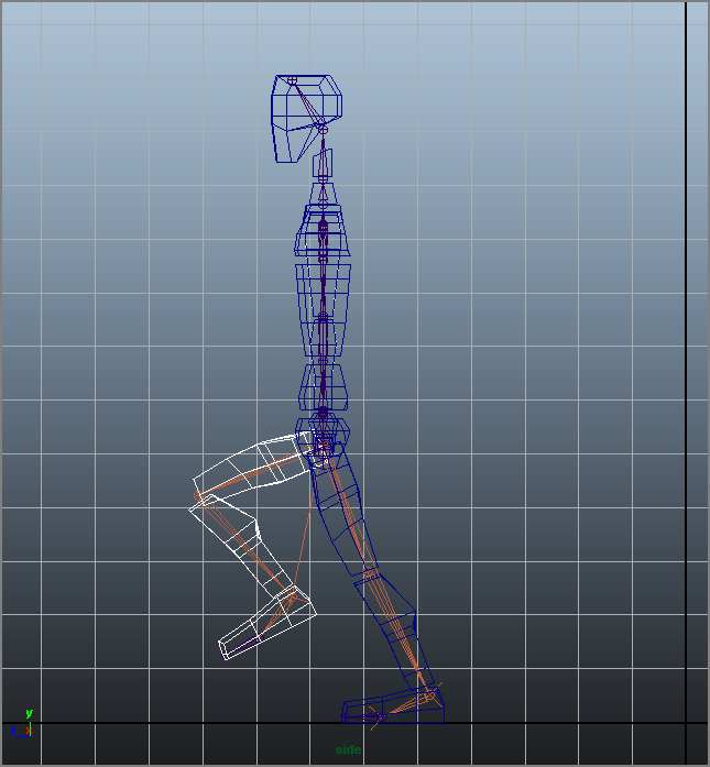
Figure 9-54: Step 7’s pose (frame 25)
The next pose should match the pose in frame 10, although with the other leg. Continue the cycle, with each successive pose matching the one 15 frames before it on the opposite side.
At the end of this chapter, you’ll take this one step further and create a simple character animation rig for the entire Block Man so you can have a nicely functioning character for animation.
Further Uses for IK Chains
Many animators use IK chains more often in effects animation than in character work. IK chains can drive whips and ropes, flutter flags, bounce ponytails, and pump pistons as well as move legs and arms. For example, you can use a different type of IK chain, the spline IK chain, to control the shape of your bone chain with a NURBS spline. This IK chain is great for snakes and other long, deforming objects.
To create a spline IK chain, choose Skeleton ⇒ IK Spline Handle Tool, and then select your top joint and end effector. Maya creates a spline running the length of the bone chain. Adjusting the curvature of the spline in turn drives the bones, which in turn drive the geometry bound to them. Figure 9-55 shows a spline curve affecting the curvature of the bones in its spline IK chain.
Figure 9-55: A spline IK chain is driven by the curvature of a NURBS spline. Adjusting the curve’s CVs moves the joints.

Basic Relationships: Constraints
As you know, Maya is all about the relationships between object nodes. You can create animation on one object based on the animation of another object by setting up a relationship between the objects. The simplest way to do that (outside of grouping) is to create a constraint. For example, you can “glue” one object to another’s position or rotation through a constraint.
A constraint creates a direct relationship between the source and the target object’s Translate, Rotate, or Scale attributes. This section explores six types of constraints: point, orient, scale, aim, geometry, and normal.
The Point Constraint
To attach a source object to a target object but have the source follow only the position of the target, use a point constraint. A pointconstraintconnects only the Translate attributes of the source to the target. To use this method, select the target object(s) and then Shift+click the source object. In the Animation menu set, choose Constrain ⇒ Point ![]() .
.
Constraints are based on the pivots of the objects, so a point constraint snaps the source at its pivot point to the pivot point of the target and keeps it there, even in animation. But the options allow you to set an offset that creates a gap between the source and the target.
You can constrain the same source to more than one target object. The source then takes up the average position between the multiple targets. By setting the Weight slider in the option box, you can create more of an influence on the source by any of the targets.
In Figure 9-56, a cone has been point-constrained to a sphere. Wherever the sphere goes, the cone follows. This is different from parenting the cone to the sphere in that only its translations are affected by the sphere. If you rotate or scale the sphere, the cone won’t rotate or scale with it.
Figure 9-56: A cone point that is constrained to a sphere follows that sphere’s position.
Although you can blend keyframe animation with constraint animation, as a beginner to Maya, consider that after you set a point constraint like that shown in Figure 9-56, you’re unable to control the cone’s Translate attributes because they’re being driven by the sphere’s translations.
Point constraints are perfect to animate a character carrying a cane or a sword, for example. The rotations on the sword are still free to animate, but the sword is attached to the character’s belt and follows the character throughout the scene.
The Orient Constraint
An orient constraint attaches the source’s Rotation attributes to the target’s Rotation attributes. Select the target object(s) first, and then Shift+click the source object. In the Animation menu set, choose Constrain ⇒ Orient ![]() .
.
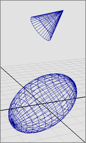
The Offset parameter allows you to set an offset in any axis. Otherwise, the source assumes the exact orientation of the target. In the case of multiple targets, the source uses the average of their orientations. Figure 9-57 shows the cone’s orientation following an elongated sphere (the target).
Figure 9-57: The cone’s rotations match the sphere’s rotations.
A rotation constraint saves a lot of hassle when you have to animate an object to keep rotating in the same direction as another object. For example, you can use the rotation of one wheel of a locomotive to drive the rotation of all the other wheels.
The Point on Poly Constraint
A point on poly constraint attaches a source object to a vertex of a mesh. Select the target object’s vertex first, and then Shift+click the object you want to place at that point (Figure 9-58, left). In the Animation menu set, choose Constrain ⇒ Point On Poly ![]() .
.
Figure 9-58: The red ball is placed on the tree branch like a fruit with a point on poly constraint.

The object is snapped to the vertex of the target at its pivot point. Even if the target object is animated and deforming, like a character, the object will stay on that vertex. Figure 9-58 (right) shows the sphere pinned to the branch at the selected vertex location.
The point on poly constraint is good for pinning objects together, such as leaves on a branch.
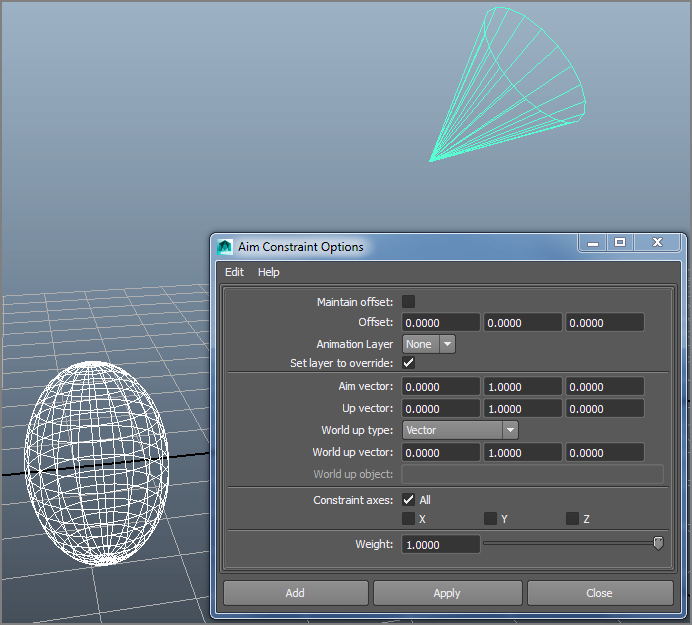
The Aim Constraint
The aim constraint adjusts the source’s rotations so that the source always points to the target object. Select the target object(s) first, and then Shift+click the source object. In the Animation menu set, choose Constrain ⇒ Aim ![]() .
.
The aim constraint has more options than the other constraints because you need to specify which axis of the source is to point to the target. You do so using the Aim Vector and Up Vector settings.
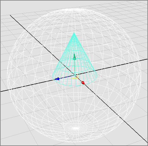
The Aim Vector setting specifies which axis of the source is the “front” and points to the target. In the cone and sphere examples, you set the Aim Vector of the cone to (0,1,0) to make the Y-axis the front so that the cone’s point aims at the sphere. If Aim Vector is set to (1,0,0), for example, the cone’s side points to the sphere. Figure 9-59 shows the cone pointing to the sphere with an Aim Vector setting of (0,1,0).
Figure 9-59: The cone aiming at the sphere
The Offset values create an offset on the source’s Rotation attributes, tilting it one way or another. The Up Vector setting specifies which way the cone faces when it’s pointing to the sphere.
Aim constraints are perfect for animating cameras to follow a subject, such as a car at a racetrack.
Geometry and Normal Constraints
The geometry and normal constraints constrain the source object to the surface of the target object (as long as it’s a NURBS or poly mesh).
With a geometry constraint, the source object attaches, at its pivot point, to the surface of the target. It tries to keep its own position as best it can, shifting as its target surface changes beneath it. Again, select the target, select the source object, and choose Constrain ⇒ Geometry.
A geometry constraint is useful when you want to keep an object on a deforming surface, such as a floating boat on a lake. Figure 9-60 shows the cone after it has been geometry-constrained to a NURBS plane that is being deformed by a Wave deformer (choose Create Deformers ⇒ Nonlinear ⇒ Wave). The cone sits on the surface as the waves ripple through, but it doesn’t rock back and forth to stay oriented with the surface.
Figure 9-60: With a geometry constraint, the cone sits on the deforming surface.

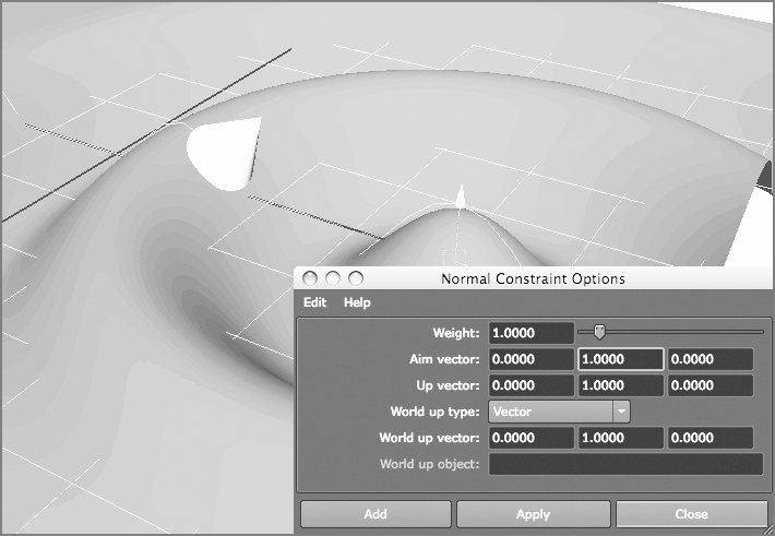
To get the cone to orient itself so that it truly floats on the surface, you need to use a normal constraint. Using a normal constraint rotates the cone to follow the surface’s normals, keeping it perpendicular to the surface.
The normal constraint is similar to the aim constraint, and its options are similar. Using the Aim Vector setting, you specify which way is up for the object to define the orientation that the source should maintain. However, this setting doesn’t constrain the location of the source to the target. If you want a floating effect, use geometry and a normal constraint to get the cone to bob up and down and roll back and forth as the waves ripple along (see Figure 9-61).
Figure 9-61: The cone now animates to float on the water surface, using both geometry and normal constraints.
Scale, Parent, Tangent, and Pole Vector Constraints
Four more constraints are possible in Maya: the scale, parent, tangent, and pole vector constraints. Simply, a scale constraint attaches the source’s Scale attributes to the target’s Scale attributes. A parent constraint constrains an object’s translation and rotation to another object by mimicking a parent-child relationship without actually parenting the objects. This keeps objects aligned without worrying about any grouping issues. You’ll have a firsthand look at this in the exercise where you rig the locomotive later in this chapter. Lucky you!
A tangent constraint keeps an object’s orientation so that the object always points along a curve’s direction. This constraint is usually used with a geometry constraint or path animation to keep the object traveling along a curve pointed in the right direction, no matter the direction of the curve. A point on poly constraint allows you to select a vertex on a poly mesh and constrain an object to that vertex. Pole vector constraints are used extensively in character animation rigs to keep IK joints from flipping beyond 180 degrees of motion.
Basic Relationships: Set-Driven Keys
A favorite feature for animation riggers is the set-driven key (SDK). An SDK establishes a relationship for objects that lets you create controls that drive certain features of a character or an object in a scene.
Before you can use an SDK, you must create extra attributes and attach them to a character’s top node. These new attributes drive part of the character’s animation. The term character is used broadly here. For example, you can set up a vehicle so that an SDK turns its wheels.
Let’s start with a simple SDK relationship between two objects. You’ll create a relationship between a ball and a cone. As the ball moves up in the Y-axis, the cone spins in the X-axis. As the ball descends, the cone spins back. You’ll then revisit the hand and set up an SDK on the skeleton that animates the model.
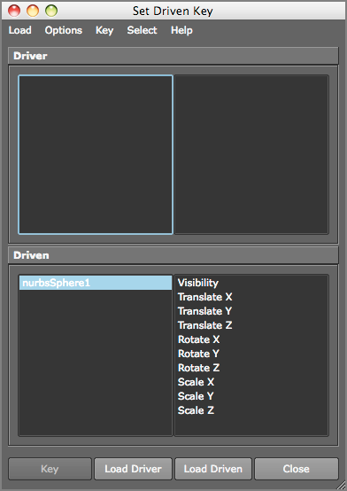
Creating a Set-Driven Key
To create a simple SDK to make a sphere control the animation of a cone’s rotation, follow these steps:
Figure 9-62: Lay out a cone and a sphere.
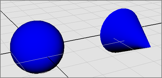
Figure 9-63: The Set Driven Key window
An Advanced Set-Driven Key: The Hand
Automating some animations on a character is indispensable to an animator. This can’t be truer than when setting up an SDK for hand control. After you model and bind a hand to a skeleton, you’re ready for an SDK.
Open the scene poly_hand_skeleton_v05.ma from the Poly_Hand_Anim project from the companion web page, or use your own file that has the hand and its skeleton and is bound (either smooth or rigid) to the skin. Your file shouldn’t have animation, though. Set your hand to the bind pose before you begin.
Creating a New Attribute
First, you’ll create a new attribute called index_pull to control a contracting finger.
Figure 9-64: The Add Attribute window
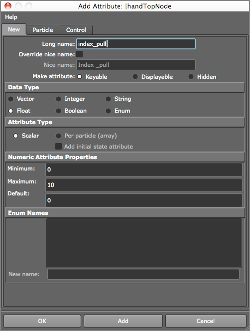
After you click OK, the Index_Pull slider appears in the Attribute Editor and the Channel Box. This attribute alone will control the entire index finger.
Assigning the Set-Driven Key
To set up the relationships with the SDK, follow these steps:
Figure 9-65: The Set Driven Key window for the hand

Figure 9-66: The bent index finger
Select the top hand node, and change the value of the index_pull attribute to animate your finger. All you need to do to pull the finger is to set keys on that attribute, without having to rotate the knuckles constantly. Furthermore, you can set up a single SDK to control the bending of all the fingers at once, or you can set up one SDK for each finger for more control.
Open the scene poly_hand_skeleton_v06.ma from the Poly_Hand_Anim project available on the companion web page to see the hand with the SDK set up on the index finger.
Application: Rigging the Locomotive
Let’s get back to our locomotive. In the previous chapter, you made sure the hierarchy and pivot placements were proper. In this exercise, you can use the locomotive_anim_v1.mb file from the previous chapter. You can also use a fancy version of the locomotive, called fancy_locomotive_anim_v1.mb; it’s set up similarly to locomotive_anim_v1.mb for the exercise. This scene is shown in Figure 9-67.
Figure 9-67: The fancier locomotive model

Setting Up Wheel Control
Your goal here is to rig the scene to animate all the secondary movements automatically based on some simple controls, such as you did for the hand earlier this chapter. In reality, the locomotive’s steam pump drives the arms that then turn the wheels on the locomotive. You’ll work backward, however, and use one wheel to drive the animation of everything else.
Because all the large wheels have the same diameter, they rotate the same as the locomotive moves. In this case, you’ll use the Connection Editor to attach the X Rotation on all the wheels to your main control wheel. You’ll pick the middle wheel to be the control. To set up the locomotive, follow these steps:
Figure 9-68: Select the middle wheel.

Figure 9-69: Connect the rotations of the two wheels.

Controlling the Wheel Arms
You’ve now automated the animation of the wheels. Next, you’ll figure out how to connect the wheel arms to the wheels and drive their motion as well. To do so, follow these steps:
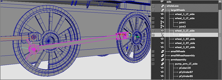
Figure 9-70: Create a joint from the middle wheel to the pump arm at the first wheel.

Figure 9-71: Group the top joint under the wheel, and then group the wheel arm under the top joint.
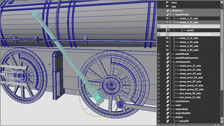
Figure 9-72: Place the end effector where the pump arm and the first wheel connect.

Figure 9-73: Group the IK handle under the locomotive’s top node.

Controlling the Pump Arm
Next, you need to attach the pump arm to the wheel arm so that it pumps back and forth as the control wheel turns. If you simply group the pump arm with the end joint of the wheel arm’s bone, the pump arm will float up and down as it pumps back and forth. You need to use a constraint to force the pump arm to move back and forth only in the Z-axis.
Figure 9-74: Line up the pivot of the pump arm with the end joint of the wheel arm joint.

Figure 9-75: The pump arm is too short!

Figure 9-76: Use vertices to extend the pump arm.

The scene file fancy_locomotive_anim_v2.mb will catch you up to this point. Compare it to your work.
Controlling the Back Wheel
All that remains is to control the animation of the back wheel and its wheel arm. To set up the wheel arm animation, follow these steps:
Figure 9-77: Create a joint to control the back wheel arm.

Figure 9-78: Create an IK handle to attach the wheel arm and the back wheel to the control wheel.
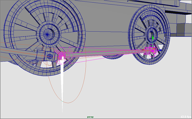
Figure 9-79: The wheel arm geometry flips over if you group the IK handle under the back wheel.
You can use fancy_locomotive_anim_v3.mb to compare your work.
Finishing the Rig
You’re almost home free with the locomotive wheel rigging. Everything works great when you rotate the control wheel. If you select the top node of the locomotive and translate the train back and forth, everything should work perfectly. Repeat the steps in the previous few sections to connect the wheel arms and wheels on the other side of the locomotive, and you’re finished! Figure 9-80 shows the completed and rigged locomotive.
Figure 9-80: The rigged fancy locomotive

Creating a Simple Character Rig
In this section, you will revisit the Block Man setup to create a more well-rounded character rig with controls like professional animators use. This rig was created by Maks Naporowski, a fellow instructor at USC and CG animator/rigger as a fairly simple biped rig for animation. (You can see some of Maks’ work in the Color Section of this book.) Bear in mind that character rigging is an involved process, and you are starting to scratch the surface here. When you are done with this rig, you will have a simple two-legged character that you can easily animate using the controls you will set up based on what you’ve already accomplished throughout this chapter.
Creating Control Shapes
Animators hardly ever manipulate and keyframe IK handles or joints directly, when a good rig is available to them, and that’s what you should keep in mind for the following rig:
Figure 9-81: Create IK handles for the arms and legs.

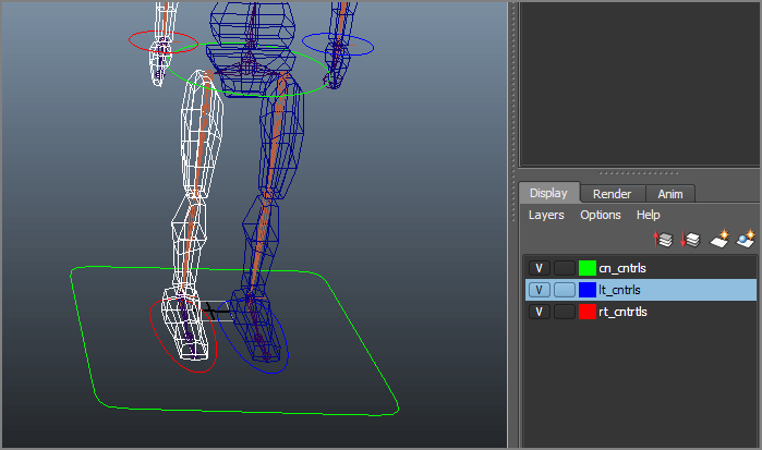
Figure 9-82: Create circles for the wrists, place them, and assign them to their own display layers.

Figure 9-83: Create control shapes for the feet, pelvis, and body.
These shapes will be the primary controllers for the animation of the character. They are easy to select and manipulate and make animation much easier.
Setting up the Controls
Now comes the tough part of rigging it all to work! You’ll group the shapes and create relationships to the skeleton here:
Figure 9-84: Grouping the controllers and IK handles
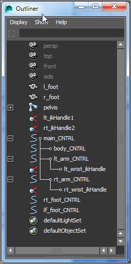
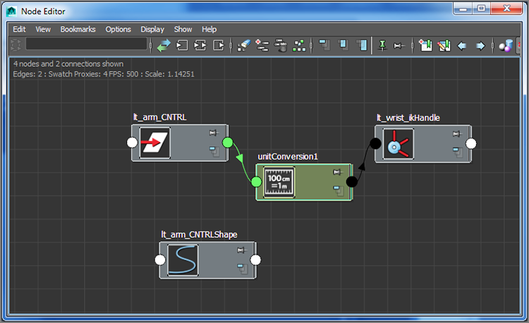
Figure 9-85: The Node Editor displays the IK handle and the circle control shape.

Figure 9-86: You’ve connected the Twist attributes.
Setting Up Heel Controls
Now let’s move on to creating some nice foot controls to allow the character to stand on his tiptoes or his heels easily. For that you will need to build a reverse joint chain to control the foot from the heel to supplement the existing leg joints.
Figure 9-87: Create a reverse joint chain for the left foot.

Figure 9-88: Parent the heel joints and ankle IK handles.

Figure 9-89: Parent the foot controls.

Figure 9-90: Moving the body control and the main control works perfectly.

Figure 9-91: Aim constrain the two joints together.
Set-Driven Keys: Heel Controls
Now let’s set up some fancy heel controls.
Figure 9-92: Create a new attribute for the foot control oval.
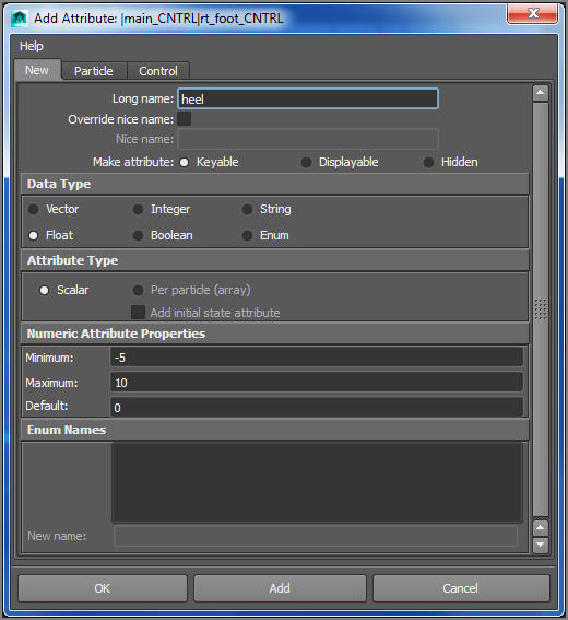
Figure 9-93: The first SDK relationship for the reverse heel joint
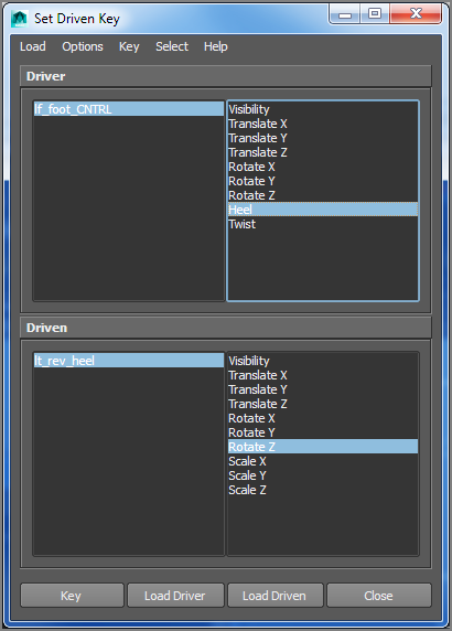
Figure 9-94: The next SDK relationship for the reverse ballFoot joint

Figure 9-95: When the Heel attribute is at 5, the heel should raise up like shown.
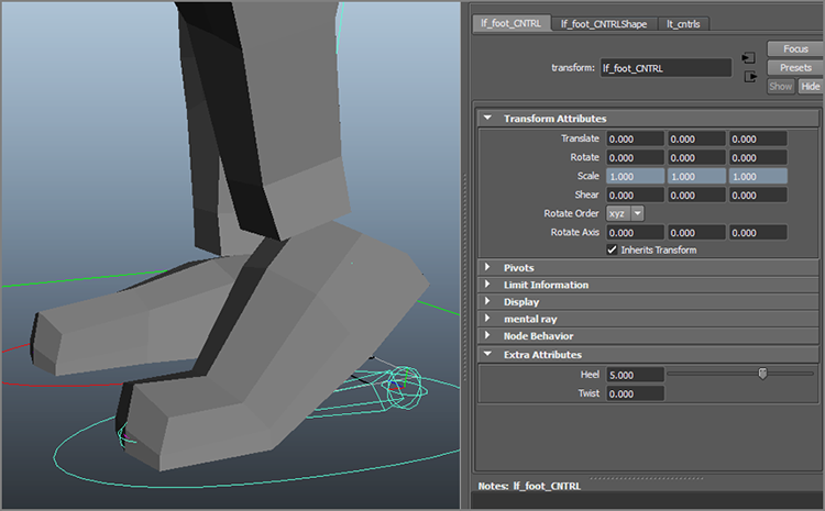
Figure 9-96: The final SDK relationship for the reverse toe joint
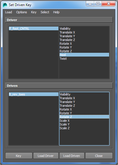
Figure 9-97: The foot position when Heel is set to 10

Make sure you’re saving your progress as you go! When you’re done, your rig should have some pretty handy controls. You will move the entire character using the main_CNTRL node. You can move the body itself while keeping sticky IK hands and feet by using the body_CNTRL node. And, of course, you control the arms/hands and legs/feet using the respective arm_CNTRL and foot_CNTRL nodes. All keyframes and animation should happen on these nodes only; you should not have to manipulate the joints or the IK handles directly at all. And that, in a somewhat confusing and long-winded nutshell, is the purpose of a character rig.
You can load the file character_rig_v01.mb from the Block_Man project to check your work or just to use as a rigged character for some animation fun!
For Further Study
Animation is as much a sport as it is an art, meaning practice makes you better. Use the rigged character from the end of this chapter to redo the walk animations from the beginning of the chapter. Also try different types and moods of walk. Can you animate a simple walk that looks happy and enthusiastic? Can you make that walk sad and lonely? Being able to convey emotion in your movement is key, and the more you try, the better you get.
Summary
In this chapter, you extended your experience with animation and learned about rigging techniques and automation. Starting with the simple Block Man, you learned how to set up a hierarchy for forward kinematics animation to create a walk cycle. Then, you used a skeleton to rig a hand for animation. Next, you learned how to bind the geometry of the hand to the skeleton using rigid, interactive, and smooth binds and how to edit the binding. You also learned how to create an IK system to drive the joints in the Block Man for an IK walk-cycle animation. After that, you learned how constraints can be used in rigging and how to set up set-driven keys to create easy controls to animate the hand. Then, you put all these rigging tricks together to rig the wheels of the locomotive to automate the animation of that complex system with a single control based on the middle wheel. And finally, you tackled a pretty tough rigging assignment in rigging the Block Man even further to have some nice options for movement using controllers.
The true work in animation comes from recognizing what to do in the face of certain challenges and how to approach their solutions. Maya offers a large animation toolset, and the more familiar you become with the tools, the better you’ll be able to judge which tools to use in your work. Don’t stop with this chapter; experiment with the features not covered here to see what happens.
Animation is about observation and interpretation. The animator’s duty is to understand how and why something moves and to translate that into their medium without losing the movement’s fidelity, tenacity, or honesty.