Chapter 6
Practical Experience
It’s time to put what you’ve learned so far into action. In this chapter, you’ll build a child’s table lamp. The lamp project uses poly and NURBS modeling techniques to give you some practical experience with a larger project in the Autodesk® Maya® software.
Learning Outcomes: In this chapter, you will be able to
- Use bevels and extrusions efficiently
- Manipulate curves to create poly meshes with Revolve ⇒ Surface
- Create a shape with a path extrusion
- See the differences between the Maya and Modeling Toolkit workflows
- Use reference images to shape your models
- See how to set up views with grid lines to align reference images for modeling
- See how images are lined up to make reference images for modeling
- Work in the Hypershade to assign image maps to objects in the scene
- Use a Boolean operation to cut holes in a mesh
- Use Maya referencing to easily share files between stages of workflow
Evaluating the Table Lamp
Download the entire TableLamp project folder structure from the book’s companion web page (www.sybex.com/go/introducingmaya2014) to your computer’s hard drive and set your project to that location.
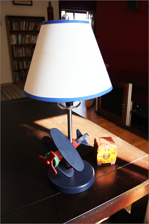
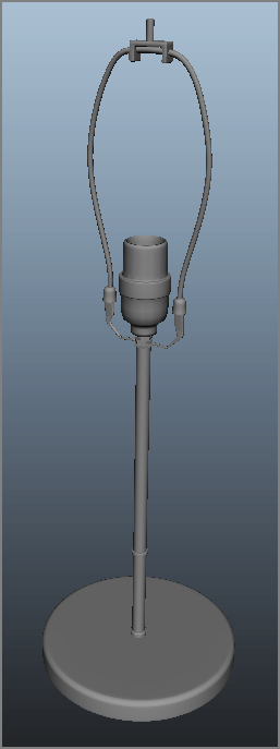
Figure 6-1 shows the lamp you’ll be modeling first in this chapter. There’s certainly enough detail in this object to make it a good exercise, but it won’t be difficult to complete. You can always return to this exercise to add more of your own detail or even redesign it for more challenge, which is something I highly recommend.
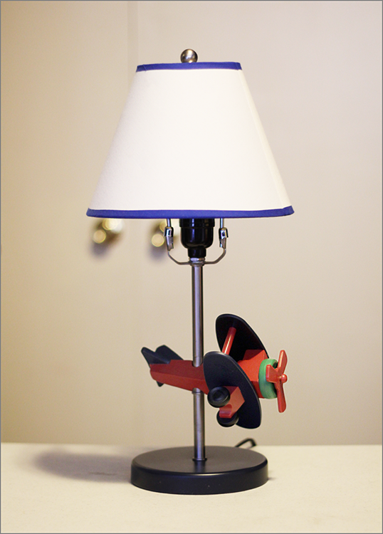
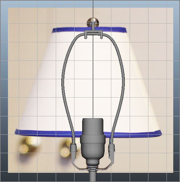
Study the photo carefully to get an understanding of the components that make up this object. You will model the parts individually instead of attacking the entire shape as a single object. This way of thinking helps complex objects become easier to understand and model. The lamp consists of the base, stem, lampshade, and toy airplane. In Chapter 3’s decorative box exercise, you used reference planes to give you an accurate guide to build the box. With the lamp, since it’s a relatively simple shape, you can use the profile photos in Figure 6-2 and Figure 6-3 as visual guides. You will not be importing them as reference planes into Maya since there’s enough perspective in the photos that it will not allow for a clean side or front profile (like you had for the decorative box in Chapter 3). But that’s OK for the lamp itself. When you set out to model the toy airplane later in this chapter, you’ll use proper reference images.
Modeling the Base
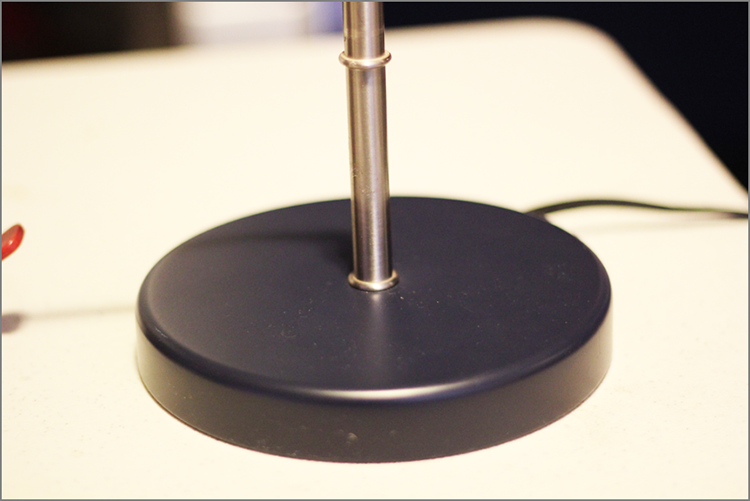
You’ll start by modeling the base. As you can see in Figure 6-4, the base is a simple cylinder with a rounded bevel at the top and a sharper bevel at the bottom. Create a TableLamp project on your hard drive, or set your project to the one copied from the companion website.
For this exercise, you’ll enable Modeling Toolkit, except where noted. Make sure to set your project to the TableLamp project you downloaded from the website. You’ll begin the model in the following steps:
1. In a new Maya scene, make sure Interactive Creation is turned off in the Create ⇒ Polygon Primitives menu, and then create a cylinder and name it
base. Scale it to (
3,
0.35,
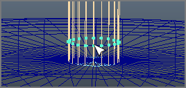
3), as shown in
Figure 6-5.
2. Select the base, and in the Channel Box, click the polyCylinder1 entry to expand the attributes to adjust the subdivisions to make the base rounder. Set Subdivisions Axis to 60 and Subdivisions Caps to 4.
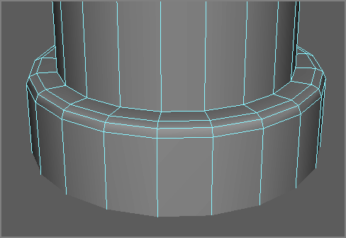
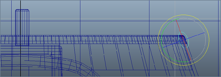
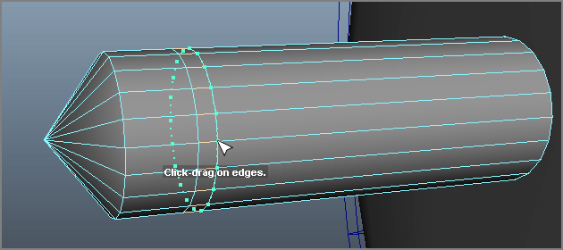
3. To create the top round bevel, select the top loop of outer edges by right-clicking the cylinder and choosing Edge from the marking menu. Then double-click one of the top horizontal edges, as shown in
Figure 6-6. Double-clicking will select the entire loop of edges automatically, whether you have Modeling Toolkit enabled or not. How convenient!
4. In the Modeling Toolkit under Mesh Editing Tools, choose Bevel. Your cursor turns into a double arrow, and a yellow readout appears in the top middle of your work panel. Click the Offset button under the Bevel Options heading in the Modeling Toolkit, and click and drag in your work window to set the Offset value to about
0.25; then click the Segments button and click and drag to set Segments to
6. Next, press the Bevel button again to turn it off, and then select the bottom loop of outer edges and repeat the bevel with an Offset value of
0.04 and a Segments value of
2.
Figure 6-7 shows the beveled base.
The scene file lampModel_v01.mb contains the finished base.
Creating the Lamp Stem
That’s it; the base is completed. Continue with your own file to create the stem next, or load the file lampModel_v01.mb in the Scenes folder of the TableLamp project from the companion website.
In Figure 6-8, you can see the stem disassembled. It’s a simple cylinder with a slight extrusion at the base and another one-third of the way up to the top, where the hooks for the lampshade and light bulb socket are. And since you don’t see the light bulb behind the lampshade, you’ll skip creating the bulb entirely.
The Stem
To begin the stem, follow along here:
1. Create a poly cylinder, and scale it to (0.2, 4.8, 0.2); place it so its bottom touches the top of the base, as shown in
Figure 6-9. Name it
stem.
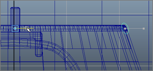
2. Choose Edit Mesh ⇒ Insert Edge Loop Tool, and insert an edge loop toward the bottom of the stem, as shown in
Figure 6-10.
3. Select the bottom row of faces, and choose Extrude from the Mesh Editing tools section of the Modeling Toolkit panel. Set Local Z to
0.05 (
Figure 6-11), and click off Extrude in the Modeling Toolkit panel to commit the extrusion.
4. Select the top edge loop on the extruded bottom of the stem, and use either Modeling Toolkit’s Bevel tool with an Offset of
0.35 and Segments of
2, or a regular Maya Bevel with a Width of
0.35 and Segments of
2.
Figure 6-12 shows the beveled base.
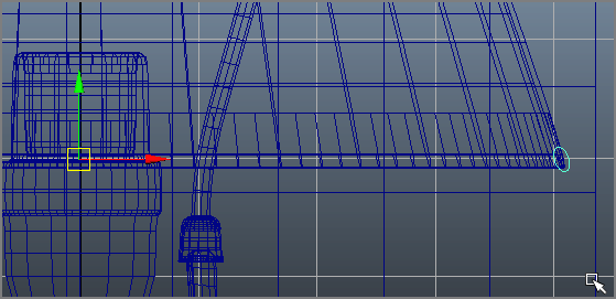
5. About one-third of the way up the stem from the base, insert two new edge loops, as shown in
Figure 6-13. These new faces will be used to create the second extrusion, as you did for the base.
6. Select the new faces between the new edge loops, and use Extrude in the Modeling Toolkit with a Local Z of
0.05. Select the top and bottom outer row of edges and use the Modeling Toolkit’s Bevel tool on them with an Offset of
0.5 (or Width if you use Maya Bevel) and Segments of
2.
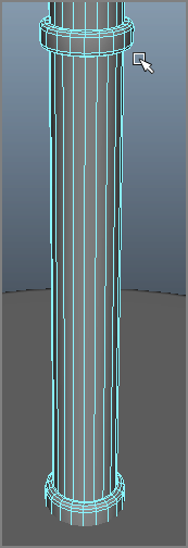
Figure 6-14 shows the beveled extrusion. Save your scene!
The Lampshade Bracket
Now that the stem is in place, on top of the lamp sits the light socket and the bracket that holds the lampshade (Figure 6-15 on the left), which you’ll tackle here.
1. Create a poly plane, rotate it 90 degrees in the X-axis, and name it reference. In the front view panel, scale it to (4.6, 1, 9.75). You will put a reference image on this plane as you did in Chapter 3. This particular scale makes the photo image fit properly.
2. Choose Window ⇒ Rendering Editors ⇒ Hypershade. In the Hypershade, create a new Lambert shader. Navigate to the Sourceimages folder of the TableLamp project, and drag the image file
stemTop.tif to the Hypershade. Click the Lambert shader, and open the Attribute Editor. MMB+drag the image file node in the Hypershade onto the
Color attribute of the selected Lambert shader to map the image onto that shader, as shown in
Figure 6-15 on the right.
3. Drag the new Lambert shader with the photo mapped to it onto the plane in the front view. Press 6 for Texture mode in the front view, and line up the plane with the top of the stem cylinder, as shown in
Figure 6-16.
4. Choose Create ⇒ CV Curve Tool, and in the front view, trace the right-side outline of the light socket. Make sure to start laying CVs from the bottom up to the top; see
Figure 6-17. This profile shape will create a hollow for the light bulb.
If the curves you are tracing seem to disappear when you deselect them, they may be hiding behind the reference plane. Simply select the reference plane and move it back in the Z-axis a tiny bit, and the curves should show up again.
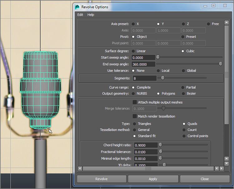
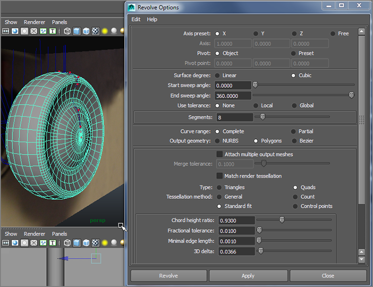
5. In the Surfaces menu set, select Surfaces ⇒ Revolve

. Set Axis Preset to Y and Output Geometry to Polygons. Then set Type to Quads and Tessellation Method to Standard Fit, as shown in
Figure 6-18. Click Revolve.
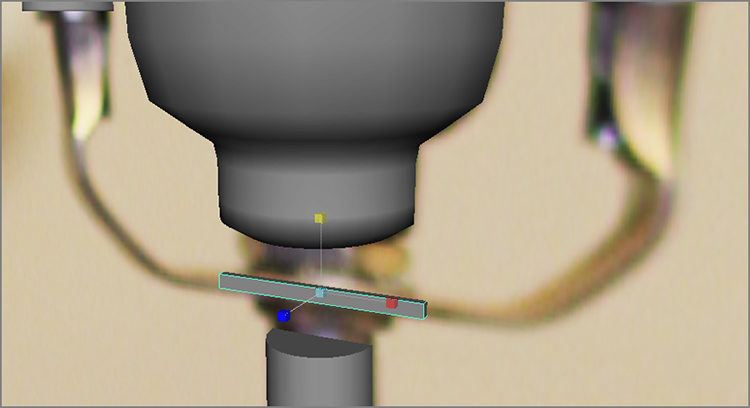
6. In the front view, trace the left-side profile of one of the bell-shaped clasps on the lampshade bracket, as shown in
Figure 6-19. With the new curve selected, choose Display ⇒ NURBS ⇒ CVs to display the CVs for the curve. Press D for Pivot Move mode, and click the Point Snaps icon (

) to snap the curve’s pivot point to the top CV as shown.
7. Select Surfaces ⇒ Revolve
again. Keep Axis Preset set to Y and Output Geometry to Polygons. Leave Type set to Quads and Tessellation Method to Standard Fit as well. Click Revolve, and you will see the bell-shaped clasp. Center the pivot point (Modify ⇒ Center Pivot), and then duplicate the bell shape (Ctrl+D) and move the copy to the other bell-shaped clasp, as shown in
Figure 6-20.
8. Delete the profile curve shapes. Name the bell shapes clasp and clasp1 and the socket geometry socket. Save your scene.
The Bracket’s Tube
To create the tubing for the top part of the bracket, follow these steps:
1. In the front view, trace a new CV curve around the bracket shape, as shown in
Figure 6-21. Use the CV placement shown as a reference to get the shape correct. This curve will be the path curve for a surface extrusion. With the new curve selected, turn on the CVs (Display ⇒ NURBS ⇒ CVs).
2. Select the right-side clasp (in this case, clasp1), and press Ctrl+H to hide it from view temporarily. Later you’ll turn on visibility again through the Outliner.
3. Select Create ⇒ NURBS Primitives, and make sure the Interactive Creation check box is off. Then choose Create ⇒ NURBS Primitives ⇒ Circle to place a circle at the origin. Using Point Snaps (
), snap the circle to the right-side end of the bracket’s path curve you created in step 1, as shown in
Figure 6-22. This circle is the profile curve for the extrusion you will create in the next step.
4. Still in the Surfaces menu set, select Surfaces ⇒ Extrude
. In the options, set Result Position to At Path and Output Geometry to Polygons, leaving Type set to Quads and Tessellation Method set to Standard Fit, as shown in
Figure 6-23. Click Extrude, and a tube will be created for the lampshade bracket. Name the tube
bracketTop, and delete the circle and path curve.
5. In the Outliner (Window ⇒ Outliner), select the hidden clasp (shown in
Figure 6-24 as the grayed-out
clasp1 node). Select Display ⇒ Show ⇒ Show Selection.
6. Make sure to position the clasps if needed to fit over the ends of the bracketTop tube you just created. Now all that remains for the lampshade bracket is the bottom bracket and the nuts that hold it in place to the stem.
The Bracket’s Bottom Part
Now for the rest of the bracket.
1. Open the Polygons menu set. Create a poly cube, and then scale and position it as shown in
Figure 6-25.
2. Select both end faces of the new cube and use the Modeling Toolkit’s Extrude tool to extrude them with a Local Z value of
0.25, as shown in
Figure 6-26. Turn off Extrude to commit the change.
3. Move the two new end faces to create a bit of a downward arc, as shown in
Figure 6-27.
4. With the two end faces selected, use Modeling Toolkit’s Extrude to extrude them with a Local Z of
0.06 and turn off Extrude. Then click the Extrude button in the Modeling Toolkit panel to extrude again, this time with a Local Z value of
0.4. Select the two new end faces and move them up to align with the bracket in the Front window. Then select each face individually in the perspective view, and rotate them to make the faces horizontal. Lastly, scale the faces in the
X-axis to match the perspective view in
Figure 6-28.
5. With the end faces selected, extrude them with a Local Z of
0.15. With the faces still selected, turn Extrude off and on again to extrude once more, this time with a Local Z of
0.6 and an Offset of
-0.05 to flare them out a bit, as shown in
Figure 6-29.
6. Press W for the Move tool. Select the top end faces individually and move them into the bell-shaped clasps.
Figure 6-30 shows the bracket ends inside the clasps.
7. Select the reference plane, and press Ctrl+H to hide it. Insert an edge loop along the middle of the bottom bracket mesh, as shown in
Figure 6-31. You’ll use this extra detail to create a valley in the bracket.
8. Select only the inside edges of that new edge loop (the part that faces the light socket), and scale them out to create a ridge inside the bracket, as shown in
Figure 6-32.
9. Use the Outliner to turn on the reference plane again. Move vertices on the bracket to shape the bracket to the reference image (
Figure 6-33). Since this part of the lamp is barely visible when the lampshade is put on the lamp, you’ll leave the detail level low. Feel free to study the pictures of the lamp bracket and create a more detailed version on your own as extra practice.
10. Select the bottom bracket piece and press 3 to see a smooth preview. It’s just a little too round, which means the mesh needs a few more subdivisions to smooth better. Press 1 to get back to the mesh’s normal view.
11. With the bracket geometry selected, choose Edit Mesh ⇒ Add Divisions
, set Division Levels to
1, and click Add Divisions. This will tessellate the mesh a little better. Preview again by pressing 3, and you should get a much nicer smoothing result. Press 1 to exit smooth preview.
12. Let’s smooth the mesh for real now. Select the bracket, and choose Mesh ⇒ Smooth
. Set Add Divisions to Exponentially and Division Levels to
1. Name the mesh
bracketBottom. Click Smooth, and check your result against
Figure 6-34. Do the same to the base of the lamp to smooth that as well.
Ah, Nuts!
Now you’ll add the nuts that hold the bracket to the stem.
1. In the top view, create a poly torus, name it nut, and move it to the side in the X-axis so you can work on it unimpeded. In the Channel Box, click polyTorus1, and change Subdivisions Axis to 6 and Subdivisions Height to 5.
2. Scale the nut down in the
Y-axis to flatten it out (you can see its thickness in the left side of
Figure 6-35). Position the nut, and scale it uniformly to fit between the bracket and the stem, as shown in the right side of
Figure 6-35.
3. Duplicate the nut, and place it above the bracket.
4. Duplicate the nut again, and place it between the first copied nut and the light socket.
5. Rotate them in the
Y-axis to offset the three nuts from each other, as shown in
Figure 6-36.
Lampshade Mount
Finally, for the lampshade bracket, you need the lampshade mount (Figure 6-37) at the top of the tubing you created.
1. Create a poly cube. Scale and position it to fit the top of the tube, as shown in
Figure 6-38.
2. Place two edge loops on either end of the cube, as shown in
Figure 6-39.
3. Select the bottom faces on both ends and extrude them with a Thickness of
0.35 to create the flanges on the mount, as shown in
Figure 6-40.
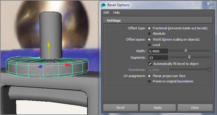
4. Select the mount as an object (not in component mode) and choose Edit Mesh ⇒ Bevel
to bevel it using traditional Maya Beveling with a Width of
0.7 and Segments of
2, as shown in
Figure 6-41. Name the mesh
mount.
5. Place a properly sized poly cylinder on top for the screw, and name it screw. Select the top edge loop and put a bevel on it, and the lamp’s lampshade bracket is complete. Select the reference plane and delete it; you don’t need it anymore.
Figure 6-42 shows the lamp so far. Save your work.
Modeling the Lampshade
The lampshade will be fairly easy to create. You can continue with your own scene or load lampModel_v02.mb from the Scenes folder of the TableLamp project from the companion website. You will use another reference to create the lampshade here:
1. In the front view panel, create a poly plane and rotate it 90 degrees in the X-axis. Move it up to the lampshade bracket and name it reference2.
2. Open the Hypershade (Window ⇒ Rendering Editors ⇒ Hypershade) and create a new Lambert shader.
3. In the Sourceimages folder of the TableLamp project, drag the image file lampShade.tif into the Hypershade. Select the new Lambert shader, and open the Attribute Editor. MMB+drag the new lampShade.tif image file node onto the Color attribute of the new Lambert shader, and assign it to the new reference plane.
4. The photo is a perfect square, so you need only uniformly scale the reference plane and then position it, as shown in
Figure 6-43.
5. You will create the blue stripes and the white lampshade as separate objects. First, trace a CV curve starting at the top and running down along the right edge of the lampshade. Before completing the curve, at the bottom of the shade, lay down CVs to loop back up along the edge a little to the left to make the line double wide, as shown in
Figure 6-44.
6. This curve is open at the top (
Figure 6-45, left), so you will have to close it. Select the profile curve, and in the Surfaces menu set, choose Edit Curves ⇒ Open/Close Curves. The curve closes but in a bizarre way (
Figure 6-45, middle). Select the offending CVs, and move them to make the line more like
Figure 6-45, right.
7. Select the closed profile curve, and in the Surfaces menu set, choose Surfaces ⇒ Revolve
. Keep the Axis preset at Y, Output Geometry at Polygons, and Tessellation Method as Standard Fit as before. This time, set 3D Delta to
0.04 for a cleaner resulting mesh. Click Revolve, and your lampshade is created. It seems to be offset, however, as you can see in
Figure 6-46.
Nothing is perfect, including this little lampshade. It’s OK if the reference image does not exactly line up with the geometry in this exercise. If you were building something to exact scale, you would start with exact photos. In this case, though, you can simply cheat.
8. Select the profile curve for the lampshade (use the Outliner if you need to). Simply move the profile curve to the right to make the lampshade wider. Construction History allows the lampshade mesh to adjust as you move the profile curve. When you have a satisfactory sizing of the lampshade (
Figure 6-47), delete the profile curve. Name the lampshade geometry
lampshade.
9. Now for the blue trim. Create a NURBS circle, rotate it 90 degrees in the
X-axis, and place and scale it in the front view panel at the upper edge of the lampshade, as shown in
Figure 6-48. You should have an oval shape oriented as shown.
10. Press and hold D, and move the circle’s pivot point to the middle of the lampshade, as shown in
Figure 6-49.
11. Copy the oval shape, and place it at the bottom-right corner of the lampshade (
Figure 6-50). Make sure to move its pivot point to the centerline of the lamp as well.
12. Now you are ready to revolve the ovals to make the upper and lower blue trim. Select both ovals, and in the Surfaces menu set, select Surfaces ⇒ Revolve
. Keeping the same settings as before in step 7, click Revolve, and compare your results to
Figure 6-51.
13. Name the trim objects upperTrim and lowerTrim, respectively, and delete the oval profile curves as well as the reference plane. You don’t need them anymore.
As you can see in Figure 6-52, the lampshade has three metal tubes connecting it to the bracket with a metal ball over the screw. You’ll create those in the following steps:
1. Create a polygon cylinder and flatten it to make a disc. Place the disc on top of the lampshade mount, around the screw. Bevel the top and bottom loop of edges, as shown in
Figure 6-53. Name the object
disc.
2. Create a poly cylinder, rotate it 90 degrees in the
Z-axis to place it on its side in the front view panel, and name it
brace. Scale it to be a long, thin tube at about the same thickness as the bracket top tube. Place it on top of the lampshade, as shown in
Figure 6-54, and set its pivot point to the middle of the lampshade mount disc. This tube should go from the middle of the disc you just placed in the last step to the inside top of the lampshade trim.
3. Duplicate that brace tube twice, and orient and place the copies as shown in
Figure 6-55.
4. You’re almost finished with the main lamp model. Place a poly sphere at the top of the lampshade over the screw, and name it button.
Voila! You’re finished with the lamp itself and can move on to the toy airplane on its stem. Figure 6-56 shows the lamp so far and the Outliner view of its objects. You can check your work against the lampModel_v03.mb scene file in the Scenes folder of the TableLamp project from the companion website.
Making the Toy Airplane
Now all you need to add is the cute airplane to the middle of the lamp stem to complete this model. In this section, you will create the toy airplane in a new scene file, and then you’ll learn how to reference the airplane model into the master lamp scene. Referencing in Maya is similar to importing a file into an open scene. However, with a referenced scene, any changes made to the original referenced scene will automatically be reflected into the object(s) referenced into the master scene. This is great for when you are continuously making adjustments to a model used in an animation or lighting scene. The model is updated as you make the changes. It also allows for an easier workflow when more than one person is working on a project. I’ll explain referencing scenes in detail later in this chapter.
Since the toy airplane is a more complex shape than the lamp itself, you will use three image reference planes similar to those you used to create the decorative box in Chapter 3.
Reference Images
Reference images aren’t just for fun! As you’ve seen, you can import images into Maya to work directly on the reference. For a model like this airplane, it’s best to create three different image views of the model (front, side, and top) to give you the most information as you build the model. The first step, of course, is to take pictures of your intended model from these three angles. Figure 6-57, Figure 6-58, and Figure 6-59 show photos taken of the front, side, and top views of the toy airplane.
The trick here is to bring the photos into an image-editing program, such as Adobe Photoshop, and scale and edit the images to line them up as shown in Figure 6-60. The images have been copied and pasted into a larger frame, and grid lines are used to line up the major portions of the airplane, such as its wings and wheels.
Keep in mind that when you take a photo, in most cases there will be perspective shift, or parallax, in the image. Because of that shift, the different views of the same object will never exactly line up. As you can see in Figure 6-60, the bottom of the airplane wheels don’t exactly line up between the front view and the side view, even though all the other major elements of the plane are in alignment. This is because of perspective differences in the photos.
Complete accuracy isn’t what you’re after in this situation. You just want to have a reasonable reference, and this will be more than adequate. Now, you’ll import the images and create the model reference planes on which to work.
Creating Reference Planes for the Images
The reference views of the toy airplane have already been created for you. You can find them in the Sourceimages folder of the TableLamp project from the companion website. They’re shown in Table 6-1.
Table 6-1: Reference views and sizes
Why is the image resolution important? Well, it’s not so much the resolution of the photos but rather the aspect ratio of each image. To properly map these images onto the planes you’ll use in Maya, each plane has to be the same ratio in scale as its image. For example, an image that is 100×50 pixels has an aspect ratio of 2:1 and is, therefore, a wide horizontal rectangle. For it to map properly, the plane on which it’s mapped in Maya must have a scale ratio of 2:1 as well so that it’s also a wide horizontal rectangle. Otherwise, the image may distort. The more accurate your model needs to be, the more accurate your photos and their reference planes need to be.
You’ll need to create three planes for each of the three views. First make sure Interactive Creation is turned off, and then follow these steps:
1. In a new scene, go to the front view panel, and create a polygonal plane by choosing Create ⇒ Polygon Primitives ⇒ Plane
. This plane is for the front image, so in the option box set Axis to
Z, Width to
1, and Height to
0.740. Set Width Divisions and Height Divisions both to
1. Make sure the check box for Preserve Aspect Ratio is deselected, as shown in
Figure 6-61. Setting Axis to Z will place the plane properly in the front view.
2. Switch to the side view panel. Create a second plane, this time with a Width value of 1 and a Height value of 0.687. Set Axis to X, and make sure the Preserve Aspect Ratio check box is not checked.
3. Switch to the top view panel. Create a third plane with Width set to
1, Height set to
0.858, and Axis set to
Y. Make sure the Preserve Aspect Ratio box is still unchecked. Your Perspective panel should look like
Figure 6-62.
Now that all three image planes have been created with the proper aspect ratios, you’re ready to map the photos to them to create the reference for the model. You’ve already done this earlier in the chapter, but let’s take a closer look at the process now.
Mapping the Reference Planes
The pesky wire has been painted out of these reference photos. To map the photos of the airplane to the reference planes, follow these steps:
1. Open the Hypershade (Window ⇒ Rendering Editors ⇒ Hypershade). Open a file browser in your OS, and navigate to the Sourceimages folder of the TableLamp project on your hard drive.
2. Click the
airplaneFront.jpg file in your file browser, and drag it into the Work Area of the Hypershade window to import the file image. Drag the other two images (
airplaneSide.jpg and
airplaneTop.jpg) into the Hypershade as well, as shown in
Figure 6-63.
If you don’t see the image of the airplane in the icons in the Hypershade as you see in
Figure 6-63, simply right-click the file node icon and select Refresh Swatch from the marking menu.
3. Before you can assign the images to their respective planes, you must create shaders for each of the planes. In the left panel of the Hypershade window, click the Lambert icon three times to create three new Lambert shaders, as shown in
Figure 6-64. For more information about shaders and texturing, see Chapter 7, “Autodesk Maya Shading and Texturing.”
4. While still in the Hypershade Work Area, hold down the Ctrl key and MMB+drag the side-view photo swatch onto the first Lambert shader icon. Maya automatically maps the image to the color of the Lambert shader, as shown in
Figure 6-65. You can also MMB+drag the image to the Lambert Shader’s
Color attribute in the Attribute Editor like you did earlier in the chapter.
5. Ctrl+MMB+drag the other two images onto their respective Lambert shaders to connect them. Name the shaders
lambertSide,
lambertFront, and
lambertTop, respectively, by double-clicking them to open the Attribute Editor and changing their names; see
Figure 6-65.
6. Assign the shaders to the reference planes. To do so, MMB+drag the Lambert shader that is connected to the side-view image to the side-view plane in the Perspective panel. Switch the perspective view into Texture mode by pressing 6 while in that panel. You should see the image of the airplane appear, as shown in
Figure 6-66.
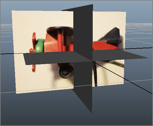
7. Drag the top-view Lambert shader to the top reference plane and the front Lambert shader to the front reference plane to assign the other two views. You should now have the three reference planes laid out as shown in
Figure 6-67.
8. All isn’t rosy yet! The front reference view and the side reference view seem to match up, but the top reference view is off. Select the top reference plane, and rotate it 90 degrees in the Y-axis. Although it’s oriented properly now, the top view is larger than the side view plane, and the images still don’t line up.
9. Uniformly scale and slightly move the top reference plane to match to the width of the airplane side view plane, as shown in
Figure 6-68.
10. Uniformly scale and move the front reference plane as well to get the airplane images to line up better, as shown in
Figure 6-69.
11. Remember that the scale of these planes is small right now. You don’t need to use real-world units for this project. However, you should scale the reference planes so that you have a larger scale with which to work. The base of the lamp you built was 6 units across, so the airplane should be about 6 units across. You will make the final adjustments later to fit the airplane into the lamp. For now, select all three reference planes and group them together by pressing Ctrl+G. Name the group node referencePlaneGroup.
12. Select the top group node and uniformly scale it so the reference planes are about 6 units large, as in
Figure 6-70.
13. To give yourself more room to work, select the front view plane and move it back, as shown in
Figure 6-71.
14. Create a display layer for the planes to make it easy to manage them later. To do so, in Layer Editor below the Channel Box, click the Create A New Layer icon (

).
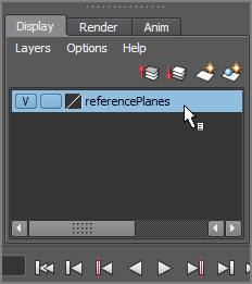
Double-click the new layer, and name it
referencePlanes in the window that pops up (see
Figure 6-72). Click Save. Your Layer Editor should resemble the one shown in
Figure 6-73.
15. Select the top group node for the three reference planes (
referencePlaneGroup), RMB+click the referencePlanes layer, and choose Add Selected Objects from the context menu. For more on Layer Editor, see the “Organizing Workflow with Layer Editor” section in Chapter 3, “The Autodesk Maya 2014 Interface.” To toggle the display of the reference planes to get them out of the way, simply toggle the box to the extreme left of the layer name. It’s currently checked with a V for Visible in
Figure 6-73.
Save your work, and “version up” so you don’t write over your previous scene files. You can download the scene file airplaneModel_v01.ma from the Scenes folder of the TableLamp project from the companion website to check your work or skip to this point. Just be sure to set your project to the TableLamp project on your hard drive after downloading the entire project from the website.
To remain in step with this chapter, make sure Interactive Creation is turned off when you create any new primitives.
Creating the Fuselage
The main part of this airplane is its body, or fuselage. This will start with a cube in the following steps:
1. In the top view, press 6 to see Textured mode, if you haven’t already. In the Layer Editor, click twice on the check box next to the Visibility toggle for the referencePlanes layer so you see an
R appear, as shown in
Figure 6-74. This sets that layer as a reference layer and makes the objects in the layer nonselectable.
2. Create a poly cube. You need to see the cube as a wireframe but still see the reference image as a textured object. In the top view panel’s menu (not the main Maya menu bar), select Shading ⇒ X-Ray to allow you to see through the box but not lose your reference image display. Place and scale the cube over the fuselage of the plane, and then move the corner vertices to match the shape of the body, as shown in
Figure 6-75.
3. Switch to the side view panel, and enable X-Ray mode (Shading ⇒ X-Ray). Move the corner vertices to get the general shape of the fuselage from the side, as shown in
Figure 6-76.
4. Switch to Object mode to select the cube, and in the Polygon menu set, choose Edit Mesh ⇒ Insert Edge Loop Tool. Then insert two edge loops toward the back of the wing, where it meets the fuselage, as shown in
Figure 6-77.
5. Use vertices to further shape the fuselage in the side and top views.
Figure 6-78 shows the result.
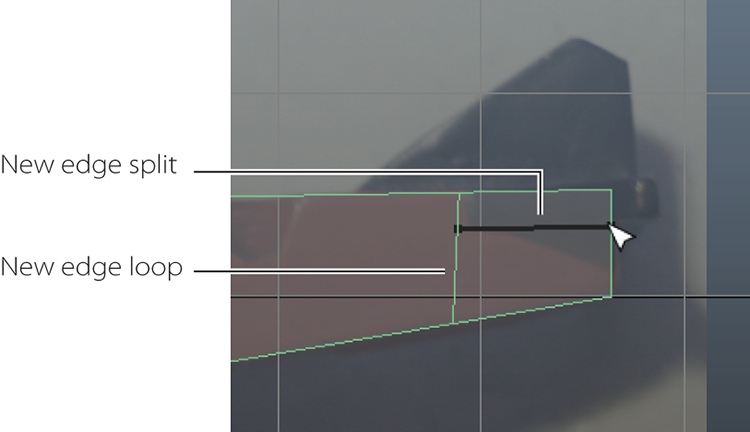
6. Using the top view, insert an edge loop at the front of the tail wings. Switch to the side view, and choose Edit Mesh ⇒ Interactive Split Tool
. In the option box, set Snap Magnets to
0, and place a new edge split along the bottom of the tail wing, as shown in
Figure 6-79. Do not click the right mouse button or hit Enter to commit the split yet.
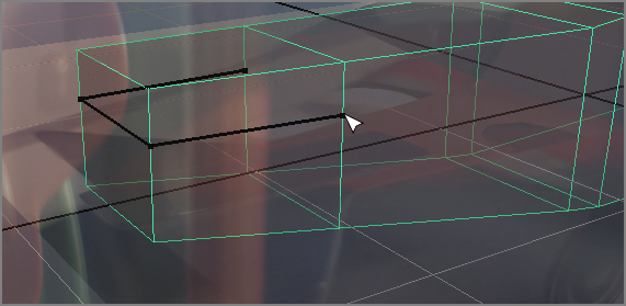
7. Switch to the persp view, and continue the edge split around the back of the fuselage, as shown in
Figure 6-80. Right-click to commit the new edges. Again, be careful not to click extra times when using the Interactive Split tool because you may inadvertently create vertices where you don’t want or see them. This can cause issues later in the modeling pipeline without warning.
If you feel comfortable, you may also opt to use Modeling Toolkit’s Multi-Cut tool in the Modeling Toolkit panel for steps 6 and 7 to make these edges instead of the Interactive Split tool. For more on how to use Multi-Cut, see Chapter 4.
8. Select both new faces on the sides of the fuselage and use the Modeling Toolkit’s Extrude to extrude them with a Local Z of
0.7 or so. Use your top view to help you gauge how far to extrude the tail wings. Move the vertices in the top and side views to shape the tail wings, as shown in
Figure 6-81.
This is an inexpensive table lamp for a child’s room. The airplane is not exactly uniform and even on both sides, so your model will also not be exactly uniform, either. You may certainly want to make your version more symmetrical.
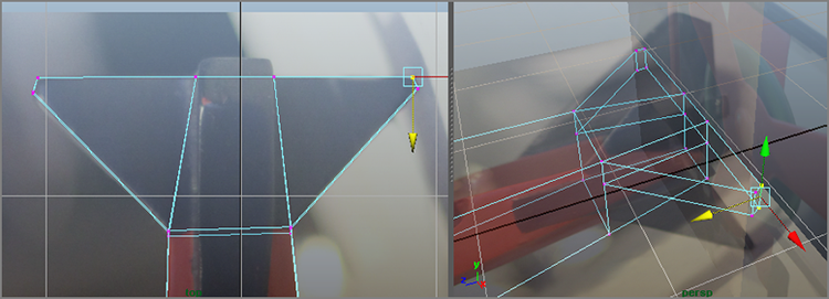
9. For the vertical wing (the stabilizer) for the tail, insert an edge loop using the top view to line it up with the vertical stabilizer. Because of the splits you created earlier in this part of the geometry, the Insert Edge Loop tool creates an edge only across the top face, as shown in
Figure 6-82. Luckily, that’s exactly what you need.
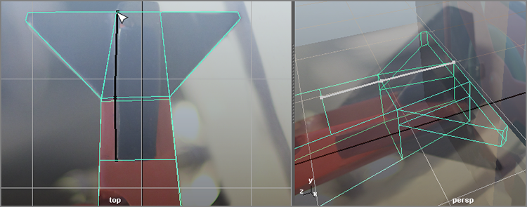
10. Enter Object mode, and select the fuselage. Press W to exit the Insert Edge Loop tool; then choose Edit Mesh ⇒ Interactive Split Tool, and place a new split as shown in
Figure 6-83. Make sure to right-click to commit the new split.
11. Create another split on the other side of the vertical wing (
Figure 6-84).
12. Select the top-center faces you just created with the Interactive Split tool, and extrude them with a Local Z of
0.7, as shown in
Figure 6-85.
13. Using the top view panel, move vertices to shape the vertical wing. Go through and move any vertices to shape the horizontal tail wings as well.
Figure 6-86 shows the overall tail shape in all four view panels.
Sometimes, things will not line up perfectly with photographed reference images like those of the lamp’s toy airplane. It’s up to you to shape the model to fit as best you can. For example, the tail section will differ slightly between the side and top views in
Figure 6-86, but that’s perfectly normal at this stage.
14. Now to concentrate on the front of the plane. There is a block that extends up from the fuselage to the top wing, as you can see in the earlier reference photo in
Figure 6-3 and in your side view. Let’s disable X-Ray view for the side view panel by unchecking Shading ⇒ X-Ray. This will make the reference image easier to see. However, the geometry of the fuselage blocks the reference, so let’s set a display override for the mesh. Select the fuselage, and open the Attribute Editor. Under the Object Display ⇒ Drawing Overrides section, check Enable Overrides, and uncheck Shading. The fuselage is now displayed as a wireframe while the reference planes are still shaded and textured.
15. Insert an edge loop toward the front of the plane, as shown in
Figure 6-87. Select the top face from the newly created section and extrude it up to just under the top wing as shown. Move the front edge vertices in the side view to shape the block to fit.
16. Select the top vertices of the block and taper the top using the front and side views as a guide for relative height. Keep in mind that perspective differences among the photos may mean the geometry may not line up exactly in all images, and that’s OK; see
Figure 6-88.
Save your work, and compare it to the scene file airplaneModel_v02.ma from the Scenes folder of the TableLamp project from the companion website to check your work, or skip to the next set of steps.
Using Booleans to Finish the Fuselage
Before you’re finished with the fuselage, you need to create the hole for the lamp’s stem and the cockpit area using Booleans.
Booleans are very impressive operations that allow you to, among other things, cut holes in a mesh fairly easily. Basically, a Boolean is a geometric operation that creates a shape from the addition of two shapes together (Union), the subtraction of one shape from another (Difference), or the common intersection of two shapes (Intersection).
Be forewarned, however, that Boolean operations can be problematic. Sometimes you get a result that is wrong—or, even worse, the entire mesh disappears and you have to undo. Use Booleans sparingly and only on a mesh that is clean and prepared. You’ve cleaned and prepped your fuselage mesh, so there should be no problems.
To begin, let’s create the hole for the lamp’s stem. The plane (as shown earlier in Figures 6-2 and 6-3) sits on the stem at an angle. The hole in the fuselage needs to go between the biplane wings and the rear stabilizer wings and run from the left-top corner to the right-bottom corner. For a Boolean, you need two meshes. The fuselage is the first mesh to be affected, and the second mesh will be a polygonal cylinder to cut the hole into that fuselage.
1. Create a poly cylinder and use the reference planes as guides to move, rotate, and scale the cylinder to fit through the fuselage, as shown in
Figure 6-89.
2. Turn off the drawing overrides for the fuselage in the Attribute Editor (in the Object Display section) so you can see the mesh as a shaded model now. With the fuselage selected, choose Edit ⇒ Delete By Type ⇒ History. This cleans out all the current history on the mesh, making the Boolean operation safer to run.
3. Select the fuselage first; then Shift+select the cylinder, and choose Mesh ⇒ Booleans ⇒ Difference. The cylinder disappears, and there is now a hole in the mesh, as shown in
Figure 6-90.
4. Now for the cockpit. With the fuselage mesh selected, delete its history as in step 2.
5. With the fuselage selected, go into the Attribute Editor, and turn off shading in
Drawing Overrides again to turn it into a wireframe. Using the reference planes, create and then position and scale another poly cylinder, as shown in
Figure 6-91.
6. Select the fuselage first and then the new cylinder, and choose Mesh ⇒ Booleans ⇒ Difference. Bam! There’s a cutout for the cockpit (
Figure 6-92). Delete the history on the new fuselage and save your work.
Cleaning Up the Fuselage
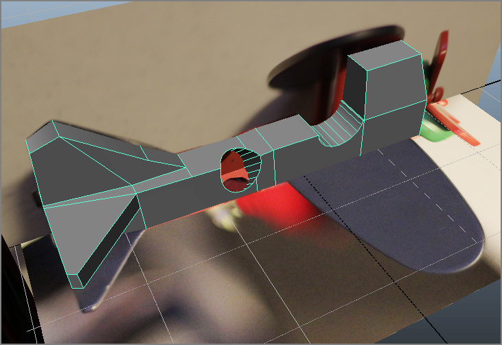
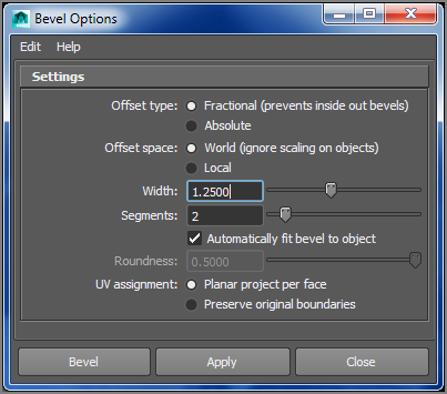
Now that you have the shape down for the fuselage, you’ll clean it up and give the outer edges some bevels. Use your model scene or airplaneModel_v03.ma to follow along here:
1. Select all the outer edges around the mesh shown in
Figure 6-93. You are not selecting two of the edges close to the hole and the edges around the stem’s hole on purpose. You will do those edges separately to avoid problems. Choose Edit Mesh ⇒ Bevel
for the traditional Maya Bevel tool. Set Offset Space to World (Ignore Scaling On Objects), Segments to
2, and Width to
1.25, as shown in
Figure 6-94; then click Bevel.
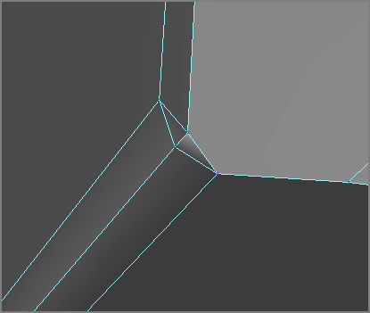
2. Select the top edge you did not bevel in the previous step, as shown in
Figure 6-95 (top). Maya Bevel that on its own (
Figure 6-95, bottom).
3. Select the edge you didn’t bevel on the bottom of the plane, as shown in
Figure 6-96. You will need to bevel this with a lower Width to avoid a weird result, since this edge is so close to the stem’s hole. Bevel the edge with a Width of
0.8 (you may have to go higher or lower if your model is slightly different).
4. This bevel isn’t quite the same size as the other bevels. This is because some of the edges near the stem’s hole are quite short and will not be able to bevel at a Width of 1.25. Your geometry may differ a little. You will manually move the vertices to make the bevel wider, as you can see in
Figure 6-97.
5. You may notice a small hole or tear where the stem hole meets the newly adjusted bevel (
Figure 6-98). This is a normal part of modeling; check the mesh for any parts that may be torn or left open when you run operations like Booleans and bevels. Simply move the vertex shown in
Figure 6-98 and snap it (by holding down V while you move the vertex) to the vertex at the bottom of the bevel, as shown in
Figure 6-99.
This is a small tear and could be left alone if you choose to skip these steps. But it’s always good to get into the habit of being very detail oriented when creating models, even if the issue may never be seen in renders.
6. Select both the vertices that are now top of each other and choose Edit Mesh ⇒ Merge, and you’ve fixed the hole!
Figure 6-100 shows the result.
Now that you’ve finished the base shape of the fuselage, it’s time to clean it up to get rid of Ngons. If you recall, Ngons are polygons that have more than four sides. This may sometimes cause problems and inefficiencies with most renderers, like mental ray, so it’s always a good idea to make sure your geometry is clean. For example, if you try beveling a mesh or some edges and you get a failed result, you can try cleaning up the mesh, as you’re about to do next.
Select the fuselage mesh, and choose Mesh ⇒ Cleanup. In the window that opens, select Faces With More Than 4 Sides and Edges With Zero Length, leaving the Length tolerance at the default, as shown in Figure 6-101. Click Cleanup, and the mesh should change ever so slightly. You will notice that some of the faces around the areas where you used a Boolean have been subdivided a bit in Figure 6-102. That is because those faces had more than four sides. Save your work and compare it to airplaneModel_v04.ma.
Creating the Propeller and Nose
Now that you’ve finished the main fuselage of the plane, you can move on to the other parts: wings, propeller, and wheels. Let’s begin with the propeller, using your work so far or the file airplaneModel_v04.ma.
1. Create a poly cylinder with Height Divisions of
2 and Cap Divisions of
5. Place, rotate, and scale the cylinder to match
Figure 6-103. You will have to enable Drawing Overrides to turn off shading for the cylinder so you can place it while looking at the reference planes. The placement should be centered on the front of your fuselage geometry, even if it looks slightly off in the reference. Remember, perspective in the photos makes the reference less than perfect.
2. Select the loop of edges shown in
Figure 6-104 (left), and scale the edges out as shown in Figure 6-104 (right).
3. Disable Drawing Overrides for a moment. Select the two edge loops shown in
Figure 6-105, and move them inward as shown.
4. Repeat steps 2 and 3 for the other side of the cylinder to create the same divot on the other side.
5. Select the cylinder, and name it propCap. Press 3 to see a smooth preview to verify how it will look smoothed. It looks exactly like you need it. Press 1 to exit Smooth Preview.
6. With the
propCap selected, choose Mesh ⇒ Smooth
. In the option box, choose Edit ⇒ Reset Settings, and click Smooth. The
propCap looks great in
Figure 6-106 with the reference planes turned off. Reenable Drawing Overrides for the
propCap to turn it into a wireframe.
7. Create a new cylinder with Axis Divisions of
12, Height Divisions of
1, and Cap Divisions of
1. Orient and scale it to fit centered on top of the
propCap, as shown in
Figure 6-107. This will be the start of the propeller itself. Name the mesh
prop.
8. Enter Face Selection mode, and select three faces around the rim of the prop disc, as shown in
Figure 6-108. Extrude these three faces with a Local Z value of
0.8, as shown in
Figure 6-109.
9. Select each of the blade’s end faces individually, and one by one scale them to create a flare at each end of the blades, as shown in
Figure 6-110.
10. If you press 3 for a smooth preview, the propeller doesn’t look very good. You need to add some edge loops to prevent the prop from becoming too mushy and soft. Press 1 to exit the smooth preview, and use the Insert Edge Loop tool to place edge loops as shown in
Figure 6-111.
11. Now if you press 3, you will have a nicer result in the smooth preview. Exit the preview, and with the prop selected, choose Mesh ⇒ Smooth. It’s not an exact fit to the toy plane’s propeller, so you may want to adjust your model accordingly; however, it will do great for your needs here.
12. For the button holding the prop to the
propCap, you need a simple shape, and there’s no need to make a hole in the prop for it either, since you won’t see the hole behind the button. Create a poly cylinder, and place it in front of the center of the prop, as shown in
Figure 6-112.
13. Select the vertex at the center of the end cap for the cylinder, and pull it out to form a point like a pencil. Then, as shown in
Figure 6-113, insert two edge loops close to each other at the top.
14. Select the faces of the pointed tip and scale them up as in
Figure 6-114. Select the mesh, and choose Edit ⇒ Smooth to create a rounded button. Place the button into the prop, as shown in
Figure 6-115.
Name the mesh propButton, and name the fuselage mesh fuselage. You can turn off Drawing Overrides for everything now. Group the airplane parts together, and call the group biplane. Save your work and compare it to airplaneModel_v05.mb.
Using Maya File References
The toy airplane is not finished yet, but you’re going to place it onto the lamp now using the Maya Reference function. References work by importing (called referencing) a Maya file into another Maya scene. When the referenced file is updated, it is automatically also updated within the scene where it was referenced. You can also very easily swap out versions of the reference file and not lose any position or animation information in the main scene. Let’s bring the airplane into the lamp now.
1. Open the last lamp model file you created, or open lampModel_v03.mb from the Scenes folder. It’s the completed lamp.
2. Choose File ⇒ Create Reference, and navigate to your latest airplane file, or use
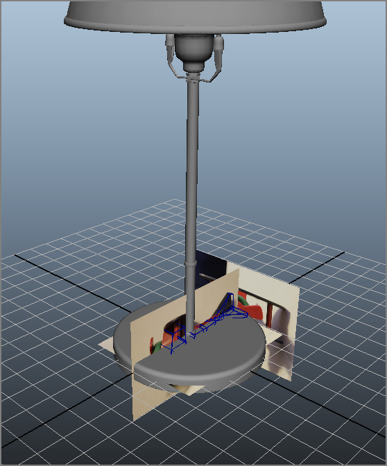
airplaneModel_v05.mb from the Scenes folder. Click Reference, and the airplane is referenced into the lamp scene, reference planes and all, as shown in
Figure 6-116.
3. Save this file. You can compare it to lampScene_v01.mb if you want.
4. If you select any part of the airplane model, you will notice that you cannot delete it. Referenced assets cannot be deleted in the master scene; you would need to go back into that Maya file itself to make such adjustments.
5. Notice in
Figure 6-117 that the reference image planes’ layer is also inserted into the scene. Until you delete these reference planes in the airplane model’s file, you can just turn this layer off for now.
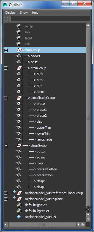
6. Open the Outliner, and at the bottom you’ll notice two new nodes in your scene that have a blue diamond next to them. This signifies a reference. You’ll also see that the lamp is in a mess. It’s not grouped at all. Silly us! Follow along with the Outliner shown in
Figure 6-118 to group your lamp’s nodes. Then save your file (compare it to
lampScene_v02.mb).
7. Now that the scene is cleaned up and saved, let’s place the airplane on the stem. Select the top group node of the toy airplane, and position it so that the plane rests on the stem about one-third of the way up.
8. Now that the plane is in position, you will notice that the plane is smaller than it looks in the photos from the beginning of the chapter. Select the top node again, and press D to move the pivot. Move the pivot to where the stem and the airplane meet and then release the D key.
9. With the pivot placed at the stem, scale the top node of the biplane to
1.2 in all three axes. Again, make sure you are doing all these actions to the top node of the biplane.
Figure 6-119 shows the placement and scaling.
Now your toy airplane is in position on the lamp (Figure 6-119), but it doesn’t have any wings or wheels. Next, you’ll go back into the airplane model file and finish the model properly. Version up and save your work. You can check against the file lampScene_v03.mb in the Scenes folder.
Finishing the Toy Airplane
You can continue with your own airplane model file or open the scene file airplaneModel_v05.ma to begin modeling the wings. Keep in mind that anytime you bevel in the rest of this exercise, you are using the Maya Bevel and not the Modeling Toolkit’s Bevel tool. You may choose to use Modeling Toolkit’s Bevel, in which case you should use the value given for Width in Maya Bevel for use as the Offset value in Modeling Toolkit’s Bevel.
1. Create a poly cube with a Width Divisions value of
9 and a Depth Divisions value of
4, and use the top and side reference planes to place, rotate, and scale it as the top wing, as shown in
Figure 6-120. Move the vertices to shape the wing in the top view.
2. Select the top and bottom edge loops around the outside edge of the wing, as shown in
Figure 6-121, and bevel them with a Width value of
0.5 and a Segments value of
2.
3. Press 3 to preview the smooth version of the wing, and make any adjustments you want. When you are satisfied with the shape, select the wing, and choose Mesh ⇒ Smooth
. Make sure Add Divisions is set to Exponentially and Division Levels is at
1. Click Smooth and compare the wing to the one shown later in
Figure 6-122. The wing should have a much closer shape to the reference shape.
4. Duplicate the wing and move it down to where the bottom wing is to create the bi-wings. Name the top wing mesh topWing and the bottom one bottomWing.
5. Use the front view to create and place two poly cylinders as the wing supports, and call them wingStrut and wingStrut1. Place the four new meshes into the biPlane group as shown in the Outliner. Figure 6-122 shows both wings in place with the reference planes turned off. Go ahead and turn off Drawing Overrides for the wings.
Making the Wheels
Now for the wheel assembly below the bottom wing.
1. Create a poly cube with a Width Divisions value of
9 and a Depth Divisions value of
2. Turn off
Shading in Drawing Overrides in the Attribute Editor, and then place the cube using the reference images. Move vertices to shape the mesh, as shown in
Figure 6-123.
2. Select the outer edges (
Figure 6-124), and bevel them with a Width value of
0.3 and a Segments value of
2.
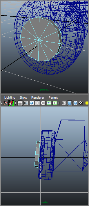
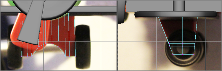
3. In the front view, create a curve to match the outline of the wheel, as shown in
Figure 6-125. Make sure the bottom two vertices are even with each other in the
Y-axis. Call the mesh
wheelAssembly.
4. Select the curve, and turn on CV display (Display ⇒ NURBS ⇒ CVs). Hold down the D key and use Point Snaps (
) to snap the pivot point to the first CV of the profile curve.
5. Select the curve and switch to the Surfaces menu set. Select Surfaces ⇒ Revolve
. Set the attributes as shown in
Figure 6-126, and click Revolve to make the wheel; name the mesh
wheel. Center its pivot (Modify ⇒ Center Pivot).
6. Delete the profile curve if you are happy with the shape. Turn off Drawing Overrides for the wheel assembly mesh. Duplicate the wheel, give the copy a scale of –1.0 in the X-axis, and move it to the other side of the wheel assembly mesh.
7. Select both wheels, and choose Modify ⇒ Freeze Transformations. Place the wheel and wheel assembly nodes under the biplane node, as shown in
Figure 6-127. Your biplane is finished!
8. Select the reference planes’ group (referencePlaneGroup) in the Outliner, and delete the reference planes. Right-click the referencePlanes layer in Layer Editor, and select Delete Layer to clean up the scene.
Save your work, and compare it to the scene file airplaneModel_v06.ma.
Updating the File Reference
Now that the biplane is finished, you need to go back into the scene file and update the biplane in that file. Open the scene file lampScene_v03.ma or open your own latest lamp scene file. Choose File ⇒ Reference Editor (Figure 6-128). In the Reference Editor window, click the airplaneModel_v04RN airplaneModel_v05.mb entry, and choose Reference ⇒ Replace Reference. Select the airplaneModel_v06.mb file, and click Reference. Save your new scene, and compare it to lampScene_v04.mb.
The biplane model will immediately update to reflect all the changes you made to add the wings and wheels. In addition, the reference planes and their display layer are gone from the scene since you deleted them from the original model file. Figure 6-129 shows the completed lamp scene.
References are a powerful way for collaboration where two people or more can work in tandem on different parts of a scene. References are also great for easily updating parts of a larger scene and in better managing these parts (a.k.a. assets). Be aware, however, that the more complicated models and hierarchies become, the more careful you have to be in keeping your scenes clean to avoid trouble with references.
Summary
In this chapter, you flexed your knowledge from the previous chapters and concentrated on creating a model of a child’s table lamp. You used many of the tools discussed in the previous chapters, from extruding to adding edge loops to using bevels and even to sculpting by moving vertices and welding them together. You also used Booleans to create the notches and holes you needed in the airplane’s fuselage, and then you fixed the problems that sometimes arise in modeling. And throughout, you used Maya references to easily update parts of a larger scene file.
Creating a model can be a lot of hard and sometimes tedious work, but when you start seeing it take shape, the excitement begins to build. From the basic shaping of the lamp’s parts to the detail of adding the airplane, you rolled up your sleeves and worked hard in this chapter to create the table lamp.
In the following chapter, you’ll tackle some simple texturing and see how to work with UVs. You’ll then add detail to the decorative box from earlier in the book by creating maps for displacement as well as color. Later in the book, you’ll light and render the table lamp and decorative box to make them look as photo-real as possible.
This doesn’t mean your modeling experience is over! There’s still plenty of detailing you can add to the table lamp and its toy airplane. For example, you can create a light bulb for behind the lampshade and even a power cord that comes out of the base.
You can also take the procedures you used in this chapter to build your own lamp or decorative box design. The important lesson to take away from this chapter is how in-depth you can get with a model and how a lengthy modeling process takes shape. Along the way, don’t forget to name your pieces and group everything in a sensible fashion.