
Chapter 2: Cozying Up to Routing Basics
In This Chapter
![]() Examining where routers fit into the OSI model
Examining where routers fit into the OSI model
![]() Enabling routing on your network
Enabling routing on your network
![]() Implementing the DHPC service on your router
Implementing the DHPC service on your router
In this chapter, I discuss the main purpose of routers and where they fit into your overall physical network infrastructure and, of course, into our old friend, the OSI model. The single main function that routers have in the network world is to move data, so much of this chapter surrounds the fact that data movement is the main goal.
Though routers are excellent in the data movement, they are capable of providing other services for the networks on which they reside. As part of these services, I also show that routers are capable of fulfilling many other network roles, by having you walk through configuring the router to act as a DHCP server for your network.
Of Routers and Routing
When you read Book III, you see how a switch is used to break a collision domain into smaller units, reducing the number of collisions that occur on a network. By reducing the collisions, you increase throughput of busy networks, because network devices do not have to repeatedly retransmit data. This situation, however, does nothing to reduce the amount of broadcast traffic on the network. Broadcast traffic on an Ethernet network is sent to the hardware address FF:FF:FF:FF:FF:FF. Every device in that broadcast domain opens and reads the data packets to the point that the device can decide that the packets do not apply to them.
In the case of an ARP request that is sent to a broadcast address, the network device needs to read the whole packet and examine the MAC address referenced in the data section of the frame. If the MAC address does not match its own address, the packet is ignored. Whereas, in the case of Ethernet frame that contains the Windows browser service election packet, the network device needs to read the network frame and will not know that the frame can be ignored until it gets to the part of the frame that identifies the workgroup or domain name which this election is for. This processing of broadcast frames can cause a great deal of work by every device on the network, and in addition to the number of broadcasts consuming available network bandwidth, negatively affect your data throughput. Enter routers.
Knowing why routers are useful
Although with a small network, you actually do not need routers, if your network is connected to the Internet, you will have at least one router. In addition to a router connecting you to the Internet, you may choose to have internal routers on a network for many reasons, such as the following:
• To accommodate a second office that is connected to your network via a telephone company using either a private line or leased lines or over the Internet.
• To increase security for systems on your network, which would include any systems where you want to restrict access such as your servers. These segments can have rules on their routers allowing only a certain range of IP addresses to connect to the segments.
• To reduce the size of the broadcast domains on your network. If broadcast domains are too large, they can create problems with network performance because of excessive background traffic. Adding routers splits the broadcast into smaller segments. Broadcast domains are covered later in this chapter.
Knowing what routers do
The main purpose of a router is to pass data from one interface on the router to another interface. For many routers, their only job is to pass traffic, and over the years Cisco has perfected the process of moving this data as fast as possible over the router. The router makes decisions about where that data needs to be based on a routing table, which you can think of as an address book.
You can use routers to divide a network into several different broadcast domains. For example, you can break a 1,000-device network into ten 100-device networks that pass data back and forth through one or more routers. Although doing so increases network complexity, because each segment needs its own IP address subnet and default gateway (which is the router), this process reduces the effect of the broadcast traffic from 1,000 devices to 100 devices, which can increase overall throughput.
![]() Switches operate at Layer 2 — the data link layer — in the OSI network model, filtering and passing data based on MAC addresses of the devices. Routers, on the other hand, operate at Layer 3 — the network layer — filtering and passing data based on the network protocol addresses, which these days typically means IP addresses.
Switches operate at Layer 2 — the data link layer — in the OSI network model, filtering and passing data based on MAC addresses of the devices. Routers, on the other hand, operate at Layer 3 — the network layer — filtering and passing data based on the network protocol addresses, which these days typically means IP addresses.
Unlike switches, which automatically build address tables, routers rely on a routing table, which is a distinct part of the router’s firmware that records routing information such as network IDs (covered in Book II, Chapter 1) and the next router or process in the packet. Routing tables must be manually configured or dynamically configured using a routing protocol such as Routing Information Protocol (RIP), described in Chapter 7 of this minibook, or Open Shortest Path First (OSPF), described in Chapter 8 of this minibook. The routing table contains a list of network IDs that look like IP addresses, and for each destination address to which the router needs to send data, the router uses a logical AND operation, which I discuss in Book II, Chapter 3. This AND operation is performed against every entry in the routing table until it finds the entry that most closely represents the destination address. The closest routing entry to the destination IP address is the routing entry that is used.
Examining the routing process
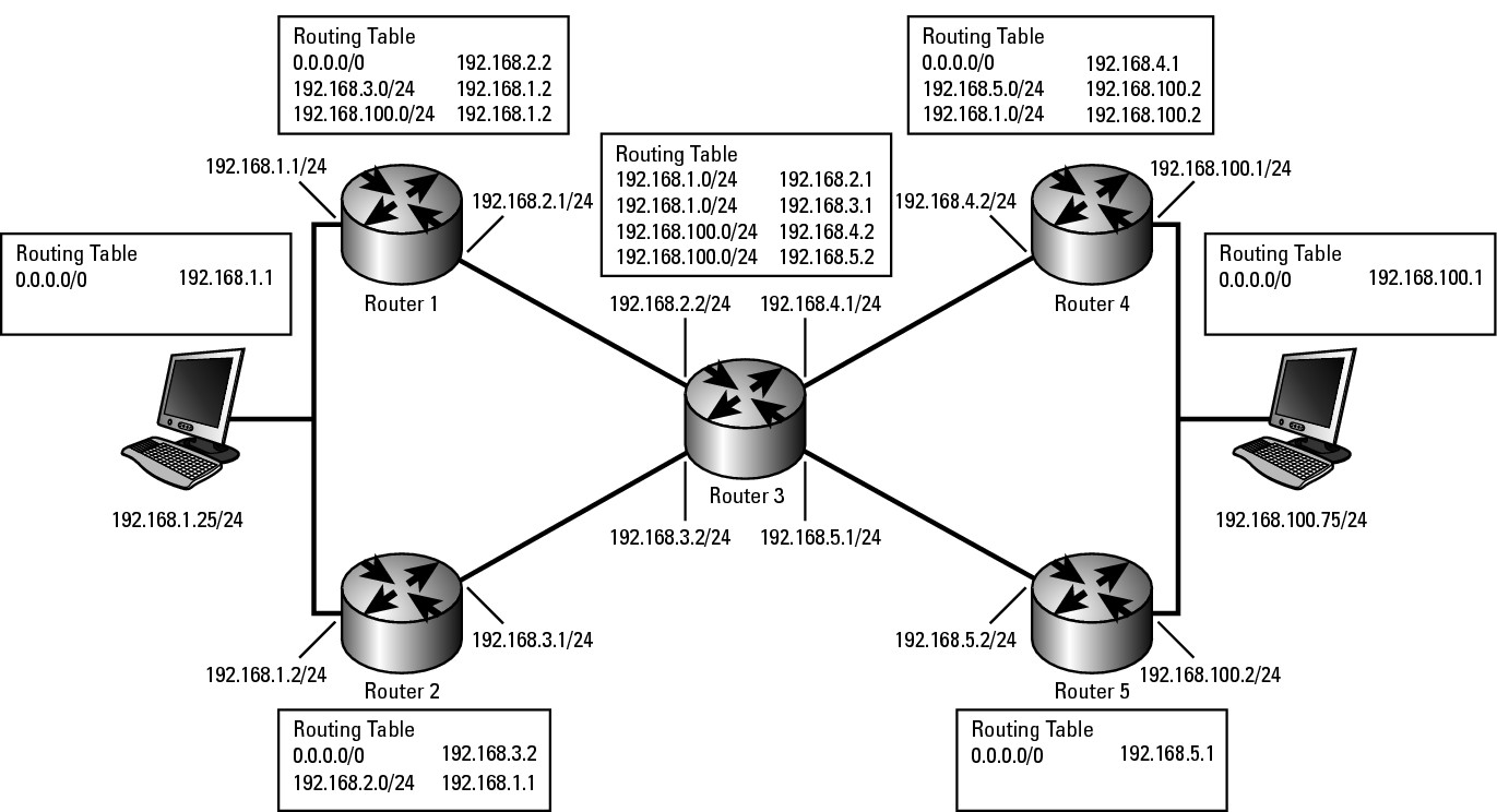
The routing process starts with a source computer that makes the first decision in the routing steps, which is illustrated in Figure 2-1. Not shown in the figure is the implicit route that each router would have for any network segments on which the routers interfaces are directly connected. The routing process goes like this:
1. The source computer at 192.168.1.25 wants to send data to the computer at 192.168.100.75, so it consults its local routing table, which, for simplicity, has only one routing entry for its default gateway (Router1).
2. As the data arrives at Router1, Router1 looks at the destination address of the IP packet and then scans through its own routing table to determine that the data should be sent off the network over Router2 as a route to the destination.
3. As the data arrives at Router2, Router2 looks at the destination address of the IP packet and determines that it does not have a specific routing entry to the destination network, but does have a default route or gateway of last resort, so Router2 passes the data on to Router3.
4. As the data arrives at Router3, Router3 has two entries in its routing table: one for the network of 192.168.100.0 through Router4 and one for the host (denoted by /32 in the routing table) of 192.168.100.75 through Router5. In this case, Router3 chooses the most specific routing table match to the destination address. Router3 then sends the data to Router5.
5. Router5 looks at the destination address of the IP packet, reviews its routing table, and finds that it is directly connected to the destination network. In that case, it sends the data directly through the interface configured for the network 192.168.100.0, which gets the data to 192.168.100.75, the final destination.
Figure 2-1: Examining the routing process.
Viewing your router’s routing table
To view the routing table on your router, you connect to the command-line interface and type the following commands:
Router2>enable
Password:
Router2#show ip route
Codes: C - connected, S - static, R - RIP, M - mobile, B - BGP
D - EIGRP, EX - EIGRP external, O - OSPF, IA - OSPF inter area
N1 - OSPF NSSA external type 1, N2 - OSPF NSSA external type 2
E1 - OSPF external type 1, E2 - OSPF external type 2
i - IS-IS, su - IS-IS summary, L1 - IS-IS level-1, L2 - IS-IS level-2
ia - IS-IS inter area, * - candidate default, U - per-user static route
o - ODR, P - periodic downloaded static route
Gateway of last resort is 192.168.5.10 to network 0.0.0.0
C 192.168.5.0/24 is directly connected, FastEthernet0/1
C 192.168.1.0/24 is directly connected, FastEthernet0/0
192.168.100.0/24 is variably subnetted, 2 subnets, 2 masks
S 192.168.100.0/24 [1/0] via 192.168.5.2
S 192.168.100.75/32 [1/0] via 192.168.5.5
S* 0.0.0.0/0 [1/0] via 192.168.5.10
Note that the routing table output includes a list of all known routes and the routing protocol that those routes were learned from. In this case, two networks are directly connected (C) to the routers’ interfaces: 192.168.5.0/24 and 192.168.1.0/24. Directly connected interfaces are always added to the routing table. Because the router is directly connected to those networks, the router knows that data can be sent to them. In addition to these directly connected networks are three static (“S”) or manually typed routes, one for a network (192.168.100.0/24), one for an IP host (192.168.100.75/32), and one for everything else (0.0.0.0/0). The last route is the default gateway or gateway of last resort, which means that if a better route is not found, this route is chosen.
![]() After you connect your router in a single router network, if you need to route only to directly connected networks, you do not have to worry about setting up static routes or enabling a routing protocol.
After you connect your router in a single router network, if you need to route only to directly connected networks, you do not have to worry about setting up static routes or enabling a routing protocol.
In the preceding routing table, you have routes to all systems on the 192.168.1.0/24 and 192.168.5.0/24 networks. For data going to either of these networks, you use the appropriate router interface, FastEthernet0/0 or FastEthernet0/1. If you have data for a system on the 192.168.100.0/24 network, you send that data on to the next router, which is found at 192.168.5.2. Bear in mind that this next router must be on a network to which you are directly connected. There is one routing table entry for the 192.168.100.0/24 network, but there is also the exception for the address of 192.168.100.75/32. The host 192.168.100.75 has a special route and the router passes the data to the router 192.168.5.5, rather than to the normal router for that network (192.168.5.2). You might use a special route such as this one if, for example, you want to use different security settings that make it easier (or harder) to communicate with system 192.168.100.75; or, perhaps the physical links going from that router may be faster (or slower), and based on the role of 192.168.100.75, using links with specific speed settings makes more sense. The point is that you tailor your routing table to pass data for sections of the same network over different paths, and the router always chooses the route based on the route that most closely matches the destination address.
Enabling Routing
It may seem strange, but when you first enable your router and configure IP addresses for its interfaces, the router will not actually route data. First, you must “tell” the router it is allowed to do so by following these steps:
Router2>enable
Password:
Router2#configure terminal
Enter configuration commands, one per line. End with CNTL/Z.
Router2(config)#interface fastEthernet 0/0
Router2(config-if)#ip address 192.168.1.240 255.255.255.0
Router2(config-if)#no shutdown
Router2(config-if)#exit
Router2(config)#interface fastEthernet 0/1
Router2(config-if)#ip address 192.168.5.1 255.255.255.0
Router2(config-if)#no shutdown
Router2(config-if)#exit
Router2(config)#ip routing
Router2(config)#exit
The first part of this process sets up your network interfaces. The key to allowing your router to route traffic between its configured interfaces is found in the ip routing command, which turns on the routing processes.
Unlike with switches, where every interface (or port) on a switch is enabled by default, with routers, you have to specifically tell a router to enable an interface, by specifying the no shutdown command when you are in Interface Configuration mode.
Working with DHCP
As I mention in the introduction to this chapter, services that are not router-related are also available on your router — for example, the Dynamic Host Configuration Protocol (DHCP) service. You can use DHCP to hand out IP address configuration to devices on your network. Servers on your network can perform this job, but in some cases, such as in a small office without a server, you can use your router to perform this role. When a DHCP server cannot be placed on a network, your router can also play the role of an IP Helper or DHCP Relay. You can find out more about IP Helper in the later section “Getting DHCP help from the IP Helper.”
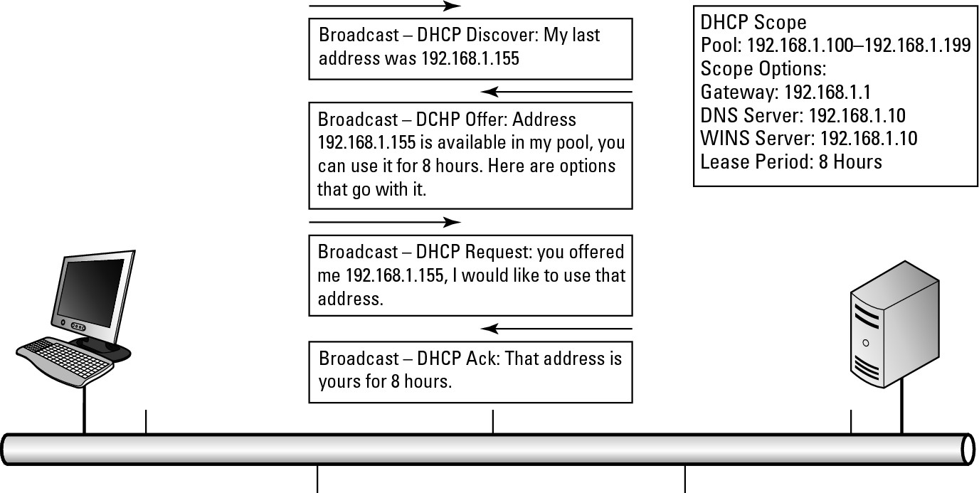
Here is the basic four-step DHCP address acquisition process (also illustrated in Figure 2-2):
• DHCP Discover: The client device sends out a request for all DHCP servers available on the network to provide an address if they have one available.
• DHCP Offer: All DHCP servers on the network that have an available address respond. The client device may receive multiple offers if multiple servers are on the network.
• DHCP Request: The client chooses one offer and sends a request back to the DHCP server. Because the client is not authorized to use the offered address yet, the DHCP Request is still a broadcast. The client accepts the first offer received unless another offer matches the last IP address that the client had.
• DHCP Ack or DHCP NAck: Typically, the DHCP server finalizes the process with an acknowledgment, or Ack, allowing the client device to start using the address. In rare cases, the server issues a Negative Acknowledgment, or NAck, because it may have decided that the address is not available in the milliseconds that have passed since it offered the address. Far more likely is that a NAck would come from a second, but malfunctioning, DHCP server, which sees the DHCP Request going to the first DHCP server and refuses it because it was not the address it offered. Its refusal is the malfunctioning part of this scenario because, if the DHCP Request was not offered for the second server, it should have been ignored.
Figure 2-2: Examining the DHCP process.
I have seen cases where multiple DHCP servers on the same network segment are configured for non-overlapping scopes (the DHCP service configuration of the configuration information it will hand out) on that network segment. One server offers an IP address, but when the client requests the address, the other server sees the request and issues a NAck, because it did not offer that address. This situation is not supposed to happen, because a DHCP server should NAck only an address it offers. When this NAck problem starts to happen, typically all computers on your network will slowly lose their IP configuration. You can quickly identify the problem by doing a network packet capture with a tool such as Wireshark (refer to Book I, Chapter 4, for more on Wireshark). Wireshark tells you the IP address and MAC address of the other DHCP server. You can use the information from Wireshark to locate the offending DHCP server and shut it down.
![]() All this traffic is broadcast traffic because until the client device receives the final acknowledgement, it is not allowed to use the offered address; so it does not have a valid IP address on the network.
All this traffic is broadcast traffic because until the client device receives the final acknowledgement, it is not allowed to use the offered address; so it does not have a valid IP address on the network.
Once the client has the address, it keeps the address until it reaches eight hours, or whatever the configured lease period is. At the end of the lease period, if the client has not renewed its lease or obtained a lease from another source, it has to relinquish the use of that address and attempt to reach a DHCP server to get another address. At the same time, even if the device is turned off after getting its lease, the DHCP server has “contracted” not to give that address to any other device until the lease period expires.
Before the lease expires, the client will attempt to renew its lease to avoid being in a situation where it does not have a valid working IP address. This process works at these time intervals:
• 50 Percent — Lease Renewal: At 50 percent of the lease period, the client will attempt to renew its lease. This renewal is a unicast message directly to the DHCP server, which is allowed because, unlike the original lease process, the client and the server both have valid IP addresses on the network through which they can communicate. The goal is that the client will be able to renew its lease and never be without an IP address. If the lease renewal is successful, it is renewed to the original lease period, providing that it has not been modified on the server.
So with an eight-hour lease, at four hours, the device will attempt to renew the lease and will end up with a new eight hour lease when successful. If for some reason the device is not able to renew its lease, it will continue to attempt a renewal periodically based on the client configuration.
• 87.5 Percent — Rebinding: If the client reaches 87.5 percent of the lease period and still has not managed to renew its lease, it will attempt to locate another DHCP server to acquire a lease. This process is identical to the original lease process. So even though the client has a valid IP address on the network, it will send out a new DHCP discovery broadcast in an attempt to locate a valid DHCP server on the network. All DHCP servers that receive discovery requests will respond with an available address. If there is more than one response, the client will choose one response and send out its request for that address, and then wait to receive an acknowledgement in return. If no servers respond to this discovery request, the client will periodically make additional requests based on the client settings. During this period, the client is still allowed to use the configured IP address that it had received in its original lease.
• 100 Percent — Lease Expiry: If the client has not located another DHCP server by the time it reaches 100 percent of the lease period, the client gives up its leased address and periodically sends out DHCP discovery requests. It continues this process until it receives a response.
Setting up your DHCP server
Setting up your DHCP server is easy, involving only a few lines in your router’s configuration file. Just follow these steps:
1. Determine your network range and any addresses that you do not want to include in your pool of addresses.
2. Exclude your reserved addresses.
3. Enable the pool.
4. Specify the IP network for which to assign addresses.
5. Specify options you want to include, such as
• DNS servers
• WINS servers
• NetBIOS Node Types (b, p, m, or h)
• Lease Duration in days, hours, and minutes
If you want, you can specify the following items also:
• A location to store the DHCP database, which could be a network location. In this way, you do not lose your assigned leases if your router experiences a failure.
• Statically assign addresses to specific hosts — this is managed through their MAC addresses. In this way, you gain the flexibility to use DHCP as well as the capability to have the same device always obtain the same address, which is ideal for devices such as servers or printers.
The following code walks you through the basic process to get your DHCP server up and running for a basic network of 192.168.1.0:
Router2>enable
Password:
Router2#configure terminal
Enter configuration commands, one per line. End with CNTL/Z.
Router2(config)#ip dhcp excluded-address 192.168.1.1 192.168.1.3
Router2(config)#ip dhcp pool DHCPPool
Router2(config-dhcp)#network 192.168.1.0 255.255.255.0
Router2(config-dhcp)#domain-name cisco.com
Router2(config-dhcp)#dns-server 192.168.1.1 192.168.1.21
Router2(config-dhcp)#dns-server 192.168.1.102 192.168.2.102
Router2(config-dhcp)#netbios-name-server 192.168.1.103 192.168.2.103
Router2(config-dhcp)#netbios-node-type h-node
Router2(config-dhcp)#default-router 192.168.1.1
Router2(config-dhcp)#lease 0 0 10
Router2(config-dhcp)#exit
Router2(config)#exit
To specify storing the DHCP database in a remote location, include a line like this one in the previous configuration. This configuration line stores the database 120 seconds after an update to the local database.
ip dhcp database ftp://user:[email protected]/router-dhcp write-delay 120
When handing out address information for multiple subnets, at times you will want to specify the same options for all subnets. To do so, you create a pool at a higher level (network-wise) and configure your options there. These options are handed out to the lower level pools as well. The following configuration of three pools illustrates this functionality:
Router2>enable
Password:
Router2#configure terminal
Enter configuration commands, one per line. End with CNTL/Z.
Router2(config)#ip dhcp excluded-address 172.30.1.100 172.30.1.103
Router2(config)#ip dhcp excluded-address 172.30.2.100 172.30.2.103
Router2(config)#ip dhcp pool 0
Router2(config-dhcp)#network 172.30.0.0 /16
Router2(config-dhcp)#domain-name edtetz.net
Router2(config-dhcp)#dns-server 172.30.1.102 172.30.2.102
Router2(config-dhcp)#netbios-name-server 172.30.1.103 172.30.2.103
Router2(config-dhcp)#netbios-node-type h-node
Router2(config-dhcp)#exit
Router2(config)#ip dhcp pool 1
Router2(config-dhcp)#network 172.30.1.0 /24
Router2(config-dhcp)#default-router 172.30.1.100 172.30.1.101
Router2(config-dhcp)#lease 30
Router2(config-dhcp)#exit
Router2(config)#ip dhcp pool 2
Router2(config-dhcp)#network 172.30.2.0 /4
Router2(config-dhcp)#default-router 172.30.2.100 172.30.2.101
Router2(config-dhcp)#lease 30
Router2(config-dhcp)#exit
Router2(config)#exit
In addition to the pools and exclusions just listed, a reservation is the process by which you statically associate a single computer with an IP address using DHCP. The following code associates Bobs-pc with the address of 172.30.2.25, as long as the MAC address of Bobs-pc remains 04c8.58b0.0b2c. You repeat this process for other computers that need to keep a static address. In these cases, if another pool hands out addresses for the network 172.30.2.0/24 or 172.30.0.0/16, Bob-pc also receives the options assigned to those pools.
Router2>enable
Password:
Router2#configure terminal
Enter configuration commands, one per line. End with CNTL/Z.
Router2(config)#ip dhcp pool Bobs-pc
Router2(config-dhcp)#host 172.30.2.25
Router2(config-dhcp)#hardware-address 04c8.58b0.0b2c ieee802
Router2(config-dhcp)#client-name Bob-pc
Router2(config-dhcp)#exit
Router2(config)#exit
Watching the DHCP traffic go by
To see what is happening on your network in regard to DHCP, enable the following debug options. Though you can monitor several options (debug ip dhcp server packet is probably the most useful), you can also choose from others:
• ip dhcp server events: Reports address assignments, lease expirations, and other events that take place with the DHCP service
• ip dhcp server class: Displays class-based address allocation
• ip dhcp server linkage: Displays database linkage
• dchp detail: Displays DHCP packet contents
Here is the output for debug ip dhcp server packet:
Router2>enable
Password:
Router2#terminal monitor
Router2#debug ip dhcp server packet
DHCPD:DHCPDISCOVER received from client 0b07.1134.a029 through relay 192.168.5.1.
DHCPD:assigned IP address 192.168.5.73 to client 0a06.1335.a126.
DHCPD: DHCPREQUEST received from client 0100.2241.806c.f3.
DHCPD: DHCPDISCOVER received from client 0100.16ec.7a50.d7 on interface FastEthernet0/1.
DHCPD: Sending DHCPOFFER to client 0100.16ec.7a50.d7 (192.168.5.20).
DHCPD: broadcasting BOOTREPLY to client 0016.ec7a.50d7.
DHCPD: DHCPREQUEST received from client 0100.16ec.7a50.d7.
DHCPD: Sending DHCPACK to client 0100.16ec.7a50.d7 (192.168.5.20).
DHCPD: DHCPINFORM received from client 0100.1d6a.44f1.c4 (192.168.1.132).
DHCPD: DHCPREQUEST received from client 0100.16ec.7a50.d7.
DHCPD: unicasting BOOTREPLY to client 0016.ec7a.50d7 (192.168.5.20).
Router2#no debug ip dhcp server packet
![]() If you enable too many
If you enable too many debug options, you will affect the performance of your router and may have trouble reading items that are going across the screen. You can use the command no debug all to disable all debugging on your router.
![]() If you need to remove a specific address pairing or DHCP lease from your DHCP database, use the
If you need to remove a specific address pairing or DHCP lease from your DHCP database, use the clear command, like this command removing the lease for 172.30.1.175:
Router2# clear ip dhcp binding 172.30.1.175
You can also use clear ip dhcp binding to remove all automatic bindings (DHCP leases) from your DHCP database:
Router2# clear ip dhcp binding *
To view the DHCP database (which is common when you are trying to locate a device on the network), use the command that follows. At times, you may have an IP address or device that you need to locate, perhaps you are following up on an issue discovered from a firewall log or other source. The show command allows you to identify the MAC address of the device. From there, you can move to network switches to locate the switch port the device is connected to; or refer to client computer documentation, if you happen to record the MAC addresses before giving your network users their computers.
Router2#show ip dhcp binding 192.168.5.20
IP address Client-ID/ Lease expiration Type
Hardware address/
User name
192.168.5.20 0100.16ec.7a50.d7 Mar 14 2002 07:40 AM Automatic
To see information about your pools and their usage, use this command:
Router2#show ip dhcp pool
Pool DHCP-Pool :
Utilization mark (high/low) : 100 / 0
Subnet size (first/next) : 0 / 0
Total addresses : 254
Leased addresses : 4
Pending event : none
1 subnet is currently in the pool :
Current index IP address range Leased addresses
192.168.5.21 192.168.5.1 - 192.168.5.254 4
Finally, to determine the amount of work your router is doing to support DHCP, view its statistics for DHCP with the following command:
Router2#show ip dhcp server statistics
Memory usage 16566
Address pools 1
Database agents 0
Automatic bindings 4
Manual bindings 0
Expired bindings 15
Malformed messages 0
Secure arp entries 0
Message Received
BOOTREQUEST 0
DHCPDISCOVER 67
DHCPREQUEST 230
DHCPDECLINE 0
DHCPRELEASE 0
DHCPINFORM 19
Message Sent
BOOTREPLY 0
DHCPOFFER 34
DHCPACK 22
DHCPNAK 82
Getting DHCP help from the IP Helper
When you have a centralized DHCP server and want the ability to track all DHCP leases, you can implement an IP Helper address to forward DHCP broadcasts on to their appropriate destination. In this way, you can implement a single DHCP server as one management point where you can check the leases for any device on your network and manage all the IP subnets on your network. Each subnet that does not have its own DHCP server will be configured with an ip helper-address command. The configuration for this command follows; note that you first must change the router interface to which you will be assigning the helper.
Router2>enable
Password:
Router2#configure terminal
Enter configuration commands, one per line. End with CNTL/Z.
Router2(config)#interface fastEthernet 0/1
Router2(config-if)#ip helper-address global 192.168.1.8
Router2(config-if)#exit
Router2(config)#exit
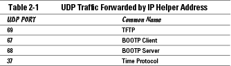
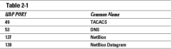
When you enable the IP Helper address, all traffic for the UDP ports listed in Table 2-1 are automatically forwarded to the address specified.
To restrict the forwarded traffic, you can specify the restrictions by adding any of the following no commands to your configuration at the Global Configuration mode.
Router2>enable
Password:
Router2#configure terminal
Enter configuration commands, one per line. End with CNTL/Z.
Router2(config)#no ip forward-protocol udp 37
Router2(config)#no ip forward-protocol udp 49
Router2(config)#no ip forward-protocol udp 53
Router2(config)#no ip forward-protocol udp 67
Router2(config)#no ip forward-protocol udp 68
Router2(config)#no ip forward-protocol udp 137
Router2(config)#no ip forward-protocol udp 138
Router2(config)#exit
Automatic Private IP Addressing (APIPA)
Many network devices that you connect to your network these days have a fallback position when DHCP services are not available on the network but the client devices are configured to use DHCP for their IP address configuration. This fallback is APIPA, a client-side process that has the client device randomly choose one of the 65,534 addresses available in the Class B network address of 169.254.0.0/16. After choosing an address from this range, the computer sends an ARP request to see whether another device on the network is using that address, and if it is not, the client device uses the address. Even though the device uses this made-up address, it continues to send out DHCP Discover broadcasts to locate a DHCP server on the network as soon as the DHCP server becomes available.
While waiting for a valid DHCP-delivered address, the device that is using an APIPA address can communicate with any other device on the network that is using an APIPA address. If two or more devices are connected to a switch and the devices are using APIPA, therefore, all of them can communicate at least with each other, but not with any other devices on the network that are using proper addresses for that network segment.