
Chapter 9: Routing with BGP and IP Multicast
In This Chapter
![]() Configuring common options for BGP and multicast routing protocols
Configuring common options for BGP and multicast routing protocols
![]() Managing BGP and multicast routing protocols with troubleshooting tools
Managing BGP and multicast routing protocols with troubleshooting tools
After the about Interior Gateway Protocols (IGP) in Chapters 7 and 8 of this minibook, this chapter takes a new tack by covering the only Exterior Gateway Protocol (EGP) discussed in this book: the Border Gateway Protocol (BGP).
Although you may or may not find it practical to implement BGP on your network, you are likely to receive some benefit from implementing multicast routing, particularly if you want multicast traffic to traverse your network without issue. In this chapter, you examine how to configure and troubleshoot the BGP protocol. In the multicast section, you see the main types of multicast routing, how to enable and configure a multicast router, and how to deal with troubleshooting information from the perspective of multicast routing.
Routing with Border Gateway Protocol (BGP)
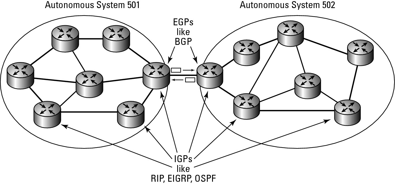
As I mention in the introduction, BGP is an External Gateway Protocol (EGP), which means it is designed to act as a routing protocol on the edge of your network, passing routing information about the structure of your network behind your gateway router. This information can then be sent on to other BGP routers, informing them which networks are found behind the BGP router. A BGP router announces routes that they have learned and can also retransmit routes learned from the IGPs found on their networks, as illustrated in Figure 9-1.
BGP’s purpose is not only to exchange its information, but also to exchange network reachability and availability information for the Autonomous Systems (AS) paths with other BGP systems on the network. This process allows all systems to construct topology graphs of the entire network infrastructure on both sides of the BGP link. This process also allows these systems to identify loops and other issues that may affect network performance and availability.
Figure 9-1: BGP routers share their routes and other routes that they have learned.
BGP has several versions of BGP, and version 4 is the current one. When two BGP systems start communicating, they attempt to use version 4 of the protocol. If one system does not support version 4, they negotiate down to older versions of the protocol until they find a version they both can use.
Routing via weights
As with other routing protocols, BGP supports modification of the preferred route through modification of metric values. BGP does so with weights. A weight is the administrative value assigned to the local router. This value can be anything between 0 and 65,535 with a default value on Cisco routers of 32,768. To force traffic through a specific router, you can have its neighbors assign higher weights to routes than they have learned from that router. So, higher weights identify a preferred route, whereas with other routing protocols lower costs identify the preferred route.
Understanding BGP commands
The basic setup of a BGP system is straightforward, but its configuration is a little reverse to the way most protocols are configured. To set up, you use the router command as usual, but you want to assign an Autonomous System number to the router in the form of router bgp as-number. The AS number identifies the network that will exist behind the BGP router. Multiple routers for the same area must have the same AS number, and they are referred to as internal neighbors, whereas external neighbors have different AS numbers. To ensure that BGP operates efficiently, list a router’s neighbors in Router Configuration mode, identifying each router’s AS number using a command such as neighbor {ip-address | peer-group-name} remote-as-a-number.
In addition to these two configuration elements, you also list the network ranges that are inside your network with a command such as network network-number [mask network-mask] [route-map route-map-name]. The network command performs two tasks. It allows you to identify the network ranges you want to advertise to other routers, which may be subnetted or supernetted portions of your network, and via the route-map portion of the command, it lists where you want that information routed. Take a look at the following commands to set up one side of a BGP connection. These same steps would be executed on your other BGP router(s).
Router2>enable
Password:
Router2#configure terminal
Enter configuration commands, one per line. End with CNTL/Z.
Router2(config)#router bgp 200
Router2(config-router)#network 192.168.5.0 mask 255.255.255.0
Router2(config-router)#neighbor 192.168.1.2 remote-as 100
Router2(config-router)#exit
Router2(config)#exit
Viewing routes in your routing table
Once you have BGP properly set up, you are able to see the routes listed in the routing table. The following shows the BGP routes in the routing table identified with a B. In addition to seeing where the route goes and how it gets there, you also see how long your router has known about that route, which is important, because if the link has been down or offline recently, this time will be very short.
Router2>enable
Password:
Router2#configure terminal
Enter configuration commands, one per line. End with CNTL/Z.
Router2#show ip route
Codes: C - connected, S - static, R - RIP, M - mobile, B - BGP
D - EIGRP, EX - EIGRP external, O - OSPF, IA - OSPF inter area
N1 - OSPF NSSA external type 1, N2 - OSPF NSSA external type 2
E1 - OSPF external type 1, E2 - OSPF external type 2
i - IS-IS, su - IS-IS summary, L1 - IS-IS level-1, L2 - IS-IS level-2
ia - IS-IS inter area, * - candidate default, U - per-user static route
o - ODR, P - periodic downloaded static route
Gateway of last resort is not set
C 192.168.5.0/24 is directly connected, FastEthernet0/1
B 192.168.6.0/24 [20/0] via 192.168.1.2, 5d15h
C 192.168.255.0/24 is directly connected, Loopback0
C 192.168.1.0/24 is directly connected, FastEthernet0/0
S 192.168.3.0/24 [1/0] via 192.168.1.1
Viewing how the protocol is functioning
As with other protocols, the show ip protocols command shows you how the protocol is currently functioning. In the following output, you see these key pieces of information from the show ip protocols command:
• The BGP AS number
• Any filters set up for incoming and outgoing data
• Synchronization with IGPs that are currently running
• Visible neighbors
• Number of equal cost routing paths
• Routers that have provided routes to this instance of BGP, including their administrative distances
Router2>enable
Password:
Router2#configure terminal
Enter configuration commands, one per line. End with CNTL/Z.
Router2#show ip protocols
Routing Protocol is “bgp 200”
Outgoing update filter list for all interfaces is not set
Incoming update filter list for all interfaces is not set
IGP synchronization is disabled
Automatic route summarization is disabled
Neighbor(s):
Address FiltIn FiltOut DistIn DistOut Weight RouteMap
192.168.1.2
Maximum path: 1
Routing Information Sources:
Gateway Distance Last Update
192.168.1.2 20 5d15h
Distance: external 20 internal 200 local 200
If, as part of the configuration, you find you need to reset a part of the routing table, use the clear ip bgp command, which clear routes by neighbor-address, a peer-group name, or all connections. To reset a neighbor connection and then reset all other connections, use the following command:
Router2>enable
Password:
Router2#clear ip bgp 192.168.1.2
Router2#clear ip bgp *
Troubleshooting BGP
To troubleshoot with BGP, you must gather information about the protocol and how it is functioning. As with other protocols, the two main sources of information are the show command and the debug command, so the place to start is by reviewing the show commands that you can use with BGP.
BGP show commands
show ip bgp displays information about your router, including its Router ID and the networks that are visible with their metric, weight, and route flag. This command shows you whether the routes are internal (on the inside of your network) or stale (not updated recently and possibly down).
![]() Notice that the RouterID is the address that was associated with the loopback interface, as with the OSPF protocol (covered in the previous chapter). Also as with the OSPF protocol, BGP uses the highest IP address of its connected interfaces as its RouterID, which you can force by using a loopback interface. To review both the OSPF protocol and how to configure the loopback interface, review the OSPF configuration in Book IV, Chapter 8.
Notice that the RouterID is the address that was associated with the loopback interface, as with the OSPF protocol (covered in the previous chapter). Also as with the OSPF protocol, BGP uses the highest IP address of its connected interfaces as its RouterID, which you can force by using a loopback interface. To review both the OSPF protocol and how to configure the loopback interface, review the OSPF configuration in Book IV, Chapter 8.
Router2>enable
Password:
Router2#show ip bgp
BGP table version is 2, local router ID is 192.168.255.254
Status codes: s suppressed, d damped, h history, * valid, > best, i - internal,
r RIB-failure, S Stale
Origin codes: i - IGP, e - EGP, ? - incomplete
Network Next Hop Metric LocPrf Weight Path
*> 192.168.6.0 192.168.1.2 0 0 100 i
The show ip bgp command has many options for viewing additional information. One of these options is neighbors. Although it will serve you well to review most of these options, I will give you an idea as to what information can be found by reviewing the neighbors option. The command reveals the following information:
• BGP version that is in use.
• Neighbors that are visible. Although the command can be run with a neighbor specified.
• BGP messages that have been seen.
• BGP connections to other routers.
• Event timer summary.
Router2>enable
Password:
Router2#show ip bgp neighbors
BGP neighbor is 192.168.1.2, remote AS 100, external link
BGP version 4, remote router ID 192.168.6.2
BGP state = Established, up for 00:11:11
Last read 00:00:11, hold time is 180, keepalive interval is 60 seconds
Neighbor capabilities:
Route refresh: advertised and received(old & new)
Address family IPv4 Unicast: advertised and received
Message statistics:
InQ depth is 0
OutQ depth is 0
Sent Rcvd
Opens: 1 1
Notifications: 0 0
Updates: 0 1
Keepalives: 14 14
Route Refresh: 0 0
Total: 15 16
Default minimum time between advertisement runs is 30 seconds
For address family: IPv4 Unicast
BGP table version 2, neighbor version 2
Index 1, Offset 0, Mask 0x2
1 update-group member
Sent Rcvd
Prefix activity: ---- ----
Prefixes Current: 0 1 (Consumes 48 bytes)
Prefixes Total: 0 1
Implicit Withdraw: 0 0
Explicit Withdraw: 0 0
Used as bestpath: n/a 1
Used as multipath: n/a 0
Outbound Inbound
Local Policy Denied Prefixes: -------- -------
Bestpath from this peer: 1 n/a
Total: 1 0
Number of NLRIs in the update sent: max 0, min 0
Connections established 1; dropped 0
Last reset never
Connection state is ESTAB, I/O status: 1, unread input bytes: 0
Local host: 192.168.1.240, Local port: 11001
Foreign host: 192.168.1.2, Foreign port: 179
Enqueued packets for retransmit: 0, input: 0 mis-ordered: 0 (0 bytes)
Event Timers (current time is 0x75ECBF0):
Timer Starts Wakeups Next
Retrans 15 0 0x0
TimeWait 0 0 0x0
AckHold 14 8 0x0
SendWnd 0 0 0x0
KeepAlive 0 0 0x0
GiveUp 0 0 0x0
PmtuAger 0 0 0x0
DeadWait 0 0 0x0
iss: 2844915809 snduna: 2844916121 sndnxt: 2844916121 sndwnd: 16073
irs: 1529136828 rcvnxt: 1529137192 rcvwnd: 16021 delrcvwnd: 363
SRTT: 259 ms, RTTO: 579 ms, RTV: 320 ms, KRTT: 0 ms
minRTT: 0 ms, maxRTT: 300 ms, ACK hold: 200 ms
Flags: active open, nagle
IP Precedence value : 6
Datagrams (max data segment is 1460 bytes):
Rcvd: 20 (out of order: 0), with data: 14, total data bytes: 363
Sent: 25 (retransmit: 0, fastretransmit: 0), with data: 15, total data bytes: 311
Other show ip bgp options include the following:
Router2>enable
Password:
Router2#show ip bgp ?
A.B.C.D IP prefix <network>/<length>, e.g., 35.0.0.0/8
A.B.C.D Network in the BGP routing table to display
all All address families
cidr-only Display only routes with non-natural netmasks
community Display routes matching the communities
community-list Display routes matching the community-list
dampening Display detailed information about dampening
filter-list Display routes conforming to the filter-list
inconsistent-as Display only routes with inconsistent origin ASs
injected-paths Display all injected paths
ipv4 Address family
ipv6 Address family
labels Display Labels for IPv4 NLRI specific information
neighbors Detailed information on TCP and BGP neighbor connections
nsap Address family
paths Path information
peer-group Display information on peer-groups
prefix-list Display routes matching the prefix-list
quote-regexp Display routes matching the AS path “regular expression”
regexp Display routes matching the AS path regular expression
replication Display replication status of update-group(s)
rib-failure Display bgp routes that failed to install in the routing
table (RIB)
route-map Display routes matching the route-map
summary Summary of BGP neighbor status
template Display peer-policy/peer-session templates
update-group Display information on update-groups
vpnv4 Address family
| Output modifiers
<cr>
BGP debug commands
The list of debug commands is quite a bit shorter than the list of show options. The list of commands includes the following:
Router2>enable
Password:
Router2#debug bgp ?
all All address families
ipv4 Address family
ipv6 Address family
nsap Address family
vpnv4 Address family
The output of the debug command includes key items such as these:
• Messages that are sent by this router
• Messages received by this router
• Items found in the received packets
Router2>enable
Password:
Router2#debug bgp all
BGP debugging is on for all address families
*Mar 18 09:22:00.327: BGP: 192.168.1.2 open active, local address 192.168.1.240
*Mar 18 09:22:00.331: BGP: 192.168.1.2 went from Active to OpenSent
*Mar 18 09:22:00.331: BGP: 192.168.1.2 sending OPEN, version 4, my as: 200
*Mar 18 09:22:00.331: BGP: 192.168.1.2 send message type 1, length (incl. header) 45
*Mar 18 09:22:00.335: BGP: 192.168.1.2 rcv message type 1, length (excl. header) 26
*Mar 18 09:22:00.335: BGP: 192.168.1.2 rcv OPEN, version 4
*Mar 18 09:22:00.335: BGP: 192.168.1.2 rcv OPEN w/ OPTION parameter len: 16
*Mar 18 09:22:00.335: BGP: 192.168.1.2 rcvd OPEN w/ optional parameter type 2 (Capability) len 6
*Mar 18 09:22:00.335: BGP: 192.168.1.2 OPEN has CAPABILITY code: 1, length 4
*Mar 18 09:22:00.335: BGP: 192.168.1.2 OPEN has MP_EXT CAP for afi/safi: 1/1
*Mar 18 09:22:00.335: BGP: 192.168.1.2 rcvd OPEN w/ optional parameter type 2 (Capability) len 2
*Mar 18 09:22:00.335: BGP: 192.168.1.2 OPEN has CAPABILITY code: 128, length 0
*Mar 18 09:22:00.335: BGP: 192.168.1.2 OPEN has ROUTE-REFRESH capability(old) for all address-families
*Mar 18 09:22:00.339: BGP: 192.168.1.2 rcvd OPEN w/ optional parameter type 2 (Capability) len 2
*Mar 18 09:22:00.339: BGP: 192.168.1.2 OPEN has CAPABILITY code: 2, length 0
*Mar 18 09:22:00.339: BGP: 192.168.1.2 OPEN has ROUTE-REFRESH capability(new) for all address-families
*Mar 18 09:22:00.339: BGP: 192.168.1.2 went from OpenSent to OpenConfirm
*Mar 18 09:22:00.339: BGP: 192.168.1.2 went from OpenConfirm to Established
*Mar 18 09:22:00.339: %BGP-5-ADJCHANGE: neighbor 192.168.1.2 Up
Routing IP Multicast Traffic
IP Multicast Routing is a huge topic because several technologies are at use in IP Multicast Routing, which means that space permits me to give only a cursory explanation of how this technology works. All networks function fine without multicast routing, but you may find some benefit to enabling it on your network.
IP Multicast Data is data that is sent out to a large group of computers but travels over the network as a single network frame. It is typically managed at the data link layer as a broadcast, though it needs to reach only a subset of all computers on the network. IP Multicast Routing is the routing of the multicast traffic.
Knowing when to use multicast routing
Some situations that will benefit from enabling multicast routing include networks or companies that want to make use of the following:
• Multicast imaging solutions for desktop OS deployment implemented across routers. These solutions often work if the solution is limited to a single network segment.
• Music on Hold and some other features of IP-based phone systems. Although you may be able to implement this as a unicast solution, multicast will greatly reduce network utilization.
• Multimedia steaming solutions that allow for multicast transmission.
• With routing protocols that send data to systems in an area or AS via multicast. Typically, these messages only need to go as far as the local data link, so no routing will be required.
Getting to know the protocols
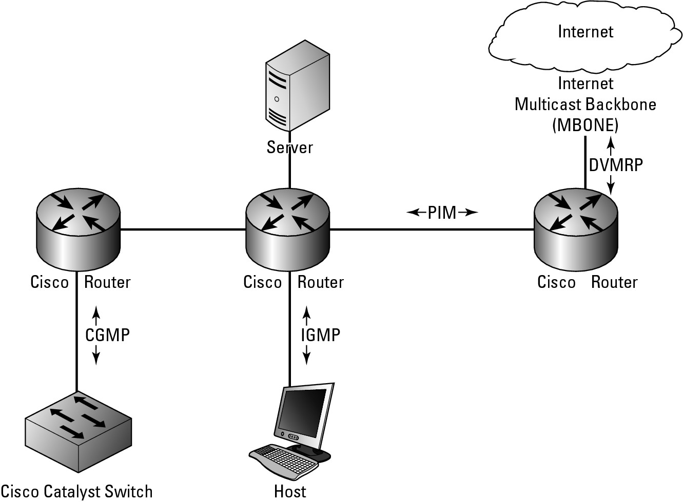
In this section, you examine three of four main protocols that are supported by the current Cisco IOS. Figure 9-2 shows you approximately where the protocols are used; the following is a list of the protocols:
• Internet Group Message Protocol (IGMP): Used to track devices on LANs that are members of multicast groups (or addresses). This protocol is used between the device and the network router.
• Protocol Independent Multicast (PIM): Used to track which multicast addresses or packets need to be sent to devices on the attached network segments or to other routers that are directly attached via network segments.
• Distance Vector Multicast Routing Protocol (DVMRP): Used to communicate with Internet-based devices on the Multicast Backbone (MBONE). Cisco supports communication between PIM and DVMRP. This protocol is the only one you will not see in this chapter, because it is used only with links to your service provider. At this time, most service providers do not support multicast traffic over their networks.
• Cisco Group Management Protocol (CGMP): A proprietary Cisco protocol used to communicate with Cisco Catalyst switches in operations that are similar to IGMP.
In Book II, Chapter 1, you may have read that multicast traffic is classed as a Class D network, with high order bits that are 1110. This yields addresses from 224.0.0.0 to 239.255.255.255 and can be written in CIDR notation as 224.0.0.0/4. The first block of these addresses, from 224.0.0.0 to 224.0.0.255, is reserved for use by routing protocols, which are covered throughout Book IV.
Figure 9-2: Multicast protocols in use in their native habitats.
Working with IGMP
IGMP provides your routers with a method to join and leave multicast groups. Multicast groups and systems that have chosen to receive data being sent to a specific multicast address. Two types of devices, other than the originator of the multicast data, are on the network, as described in this list:
• The Querier: Sends out messages asking devices connected to its network segments which devices are members of specific multicast groups.
• The Receiver: Receives multicast traffic destined for a multicast address. This device may be a client device or a router, which then forwards the data on to other hosts and routers.
![]() The querier may periodically send a request to find out what devices are in a specific group, because if all the client devices disappear, the router can stop forwarding data to some of the network segments.
The querier may periodically send a request to find out what devices are in a specific group, because if all the client devices disappear, the router can stop forwarding data to some of the network segments.
IGMP packets are actually sent using multicast, where IGMP version 1 uses 224.0.0.1 as a general query address, and IGMP version 2 uses 224.0.0.2 as its general query address. IGMP group-specific queries are actually sent to the multicast group address that the router is currently querying.
IGMP has improved over the years:
• Version 1 was defined in RFC1112, and its main goal was to introduce a query-response system. This system would be used to specify which devices on a network segment were configured to receive data that was being sent to multicast groups.
• IGMP version 2 was defined in RFC2236 and greatly improved latency issues that existed in IGMP version 1. IGMP version 2 also implemented additional features, which include a leave process, group-specific queries, and an explicit maximum query response time.
• IGMP version 3 further extended the capabilities of the protocol by allowing source filtering, which means that the routers are actually informed as to which sources the traffic is expected from.
• IGMP version 4 offered further advancement to the protocol, but the biggest single enhancement to the protocol was the inclusion of IPv6 support.
Getting into PIM
PIM is a routing protocol like RIP or OSPF. It was designed to allow multicast routing without needing to rely on other specific unicast routing protocols. There are two main modes in which PIM will operate in two main modes: Dense mode and Sparse mode.
![]() It is possible for a router to manage traffic for groups that are separately using either of these modes:
It is possible for a router to manage traffic for groups that are separately using either of these modes:
• When functioning in Dense mode, the router assumes that all other routers want to receive multicast data for a specific group. If a router receives these packets and does not need them because there are no clients that it is aware of, it sends a prune message (a message to remove a path) back to the originating router. In this Dense mode, the initial assumption of the protocol is that all routers want to get the messages or data, so more initial data is sent out over the network. This condition eventually creates a source-based multicast distribution tree. When running in Dense mode, the prune messages time out every three minutes, at which time group messages are flooded out of all interfaces again until new prune messages are received.
• Sparse mode, by contrast, involves the router assuming that no other routers want to get multicast traffic. In this case, the router closest to the host receives a multicast PIM join message from the receiver device. Directly connected routers send the PIM join message to upstream routers between themselves and the Rendezvous Point (RP), which is a router that is a designated meeting point. The RP’s job is to keep track of all multicast groups in use on the network. The RP then sends join messages upstream toward the source host. In this case, the fewest possible routers are involved with seeing and handling multicast traffic, which makes them sparse or sparsely used. Figure 9-3 shows both these operational modes, which may give you an idea about how you might use them.
Figure 9-3: How PIM could be implemented on your network.

Managing CGMP
CGMP is a Cisco implementation of an IGMP-like protocol designed specifically to interact with Cisco Catalyst switches in cases where the switch is not able to tell the difference between IP multicast data and IGMP report messages, as they are both sent to the same multicast group address when working at the MAC level. So CGMP is a helper protocol for the Catalyst switch.
Configuring multicast routing
Enabling basic multicast routing functionality on your network does not require a lot of work and can be implemented fairly quickly. Some configuration is done in Global Configuration mode and some configuration is done in Interface Configuration mode.
Enabling multicast routing
The first command that you perform in Global Configuration mode is the ip multicast-routing command, which enables multicast routing for the router. Enabling multicast routing initially does not route any data, due in fact that the default configuration leaves all router interfaces without multicast routing in their configuration.
To have multicast routing in a working configuration, you must enter each interface and configure the PIM on those interfaces. To enable PIM on an interface, you use the ip pim command, which accepts either a dense-mode or sparse-mode option. When you enable PIM on an interface, you automatically enable IGMP on those interfaces.
Supporting Sparse-Dense mode
Some groups may require Sparse mode or Dense mode in order to operate properly. Because you configure an interface for one mode or the other, you might find yourself in a catch-22 where you need both installed. To deal with this issue, Cisco supports all modes on its IOS routers, where the mode is applied to the multicast group on the router and not its interfaces. Because you may end up using Sparse mode for some groups, you require an RP to be configured. When using Sparse-Dense mode, you need to implement it throughout the network to avoid conflicts between Sparse mode and Dense mode interfaces. You implement the Sparse-Dense mode with the command ip pim sparse-dense-mode.
As just mentioned, an RP is a router on your network, so you need to assign this function to one or more routers on your network. Doing so does not require configuration on the RP router, but rather on the downstream router. The downstream router requires the address of an RP, which is accomplished by running the ip pim rp-address rp-address [access-list] [override] command using Global Configuration mode.
![]() Sparse mode implementations require the RP to be specified, although Sparse-Dense mode it is an option as you can use Auto-RP.
Sparse mode implementations require the RP to be specified, although Sparse-Dense mode it is an option as you can use Auto-RP.
Using Auto-RP rather than RPs
Rather than specifying specific RP routers, you can use Auto-RP to automate the selection and configuration of RP routers on your network. Auto-RP allows you to easily use multiple routers on your network because the RPs may be serving different groups or splitting the load over several routers. The routers could be based on the location of a multicast group’s receivers and connectivity issues could be caused by inconsistent configuration across your network.
To configure Auto-RP mode, you need to make two configuration changes, one on the router you want to act as an RP and one on the router that will manage group mappings to RPs. The first command is issued in Global Configuration mode:
ip pim send-rp-announce type number scope ttl-value [group-list access-list] [interval seconds]
whereas the second command is
ip pim send-rp-discovery scope ttl-value
Testing connectivity
You can configure your router to be a member of a multicast group so that you can test connectivity. To add your router as a member, use the ip igmp join-group group-address command in Interface Configuration mode. By default, the router uses IGMP version 2, which maximizes functionality, because version 3 has some restrictions. To change versions, use Interface Configuration mode and enter this command: ip igmp version {3 | 2 | 1. All routers on the same network segment must use the same version of IGMP, but IGMP version 2 routers will work correctly if IGMP version 1 routers are on the network. So, given the network layout, Router2 may have the following configuration commands to enable PIM routing — Router1’s setup commands then follow.
Router2>enable
Password:
Router2#configure terminal
Enter configuration commands, one per line. End with CNTL/Z.
Router2(config)#ip multicast-routing
Router2(config)#ip pim rp-address 192.168.1.2
Router2(config)#interface FastEthernet 0/0
Router2(config-if)#ip address 192.168.1.240 255.255.255.0
Router2(config-if)#ip pim sparse-dense-mode
Router2(config-if)#exit
Router2(config)#ip pim send-rp-announce FastEthernet 0/0 scope 16 group-list 1
Router2(config)#access-list 1 permit 239.0.0.0 0.255.255.255
Router2(config)#exit
To set up Router 1, use these commands:
Router1>enable
Password:
Router1#configure terminal
Enter configuration commands, one per line. End with CNTL/Z.
Router1(config)#ip multicast-routing
Router1(config)#ip pim rp-address 192.168.1.2
Router1(config)#interface FastEthernet 0/0
Router1(config-if)#ip address 192.168.1.2 255.255.255.0
Router1(config-if)#ip pim sparse-dense-mode
Router1(config-if)#exit
Router1(config)#ip pim send-rp-discovery scope 16
Router1(config)#exit
Troubleshooting multicast routing
Finally, from the “routing data book,” you check out troubleshooting a routing protocol — in this case, the multicast routing protocol — so that you can effectively locate the source of issues that arise on your network. To start, you examine the options available through the show command and then move on to the options available through the debug command.
Getting information with show
When troubleshooting for information about the multicast routing protocol, first use the show ip pim command, which requires an additional option before providing information. The following shows the major options available, from interfaces to RPs to neighbors:
Router2>enable
Password:
Router2#show ip pim ?
autorp Global AutoRP information
bsr-router Bootstrap router (v2)
interface PIM interface information
mdt Multicast tunnel information
neighbor PIM neighbor information
rp PIM Rendezvous Point (RP) information
rp-hash RP to be chosen based on group selected
vrf Select VPN Routing/Forwarding instance
Sparse mode PIM has several requirements for RPs on the network. So, if you are in Sparse mode, you want to take a close look at the several RP-based options. In addition, reviewing neighbors is always important, because if you do not see any neighbors, you probably have significant issues with the protocol implementation. Output about neighbor and rp look like the following; notice particularly the version and rp information:
Router2>enable
Password:
Router2#show ip pim neighbor
PIM Neighbor Table
Neighbor Interface Uptime/Expires Ver DR
Address Prio/Mode
192.168.1.2 FastEthernet0/0 00:02:16/00:01:26 v2 1 / S
Router2#show ip pim rp
Group: 224.1.0.1, RP: 192.168.1.2, v2, uptime 00:06:13, expires never
Group: 224.0.1.39, RP: 192.168.1.2, v2, uptime 00:05:58, expires never
Group: 224.0.1.40, RP: 192.168.1.2, v2, uptime 00:06:15, expires never
Group: 239.192.152.143, RP: 192.168.1.240, v2, v1, next RP-reachable in 00:00:31
Group: 239.255.255.250, RP: 192.168.1.240, v2, v1, next RP-reachable in 00:00:31
Also, much of the multicast routing involves requests from client devices via IGMP requests from the specific receiving devices that are connected to your network switches. To see that data, use one of the following commands:
Router2>enable
Password:
Router2#show ip igmp ?
groups IGMP group membership information
interface IGMP interface information
membership IGMP membership information for forwarding
snooping Snooping info on Catalyst Vlans
ssm-mapping Display IGMP SSM mapping info
tracking IGMP Explicit Tracking information
udlr IGMP undirectional link multicast routing information
vrf Select VPN Routing/Forwarding instance
Within the IGMP data are groups, interfaces, and membership, and although you may find that these options are the most important ones, I recommend testing all the options to see exactly what is going on.
In the following output, the groups option shows you the addresses for which the router is routing, as well as when the membership expires (because this is Sparse mode data), interface shows statistical information for the interface, and membership shows addresses or groups, who is subscribing to those addresses, and the interface on which they are working.
Router2>enable
Password:
Router2#show ip igmp groups
IGMP Connected Group Membership
Group Address Interface Uptime Expires Last Reporter
224.1.0.1 FastEthernet0/0 00:08:22 00:02:07 192.168.1.103
224.0.1.39 FastEthernet0/0 00:06:22 00:02:07 192.168.1.2
224.0.1.40 FastEthernet0/0 00:08:24 00:02:10 192.168.1.240
239.192.152.143 FastEthernet0/0 00:08:21 00:02:13 192.168.1.10
239.255.255.250 FastEthernet0/0 00:08:23 00:02:09 192.168.1.10
Router2#show ip igmp interface
FastEthernet0/0 is up, line protocol is up
Internet address is 192.168.1.240/24
IGMP is enabled on interface
Current IGMP host version is 2
Current IGMP router version is 2
IGMP query interval is 60 seconds
IGMP querier timeout is 120 seconds
IGMP max query response time is 10 seconds
Last member query count is 2
Last member query response interval is 1000 ms
Inbound IGMP access group is not set
IGMP activity: 5 joins, 0 leaves
Multicast routing is enabled on interface
Multicast TTL threshold is 0
Multicast designated router (DR) is 192.168.1.240 (this system)
IGMP querying router is 192.168.1.2
Multicast groups joined by this system (number of users):
224.0.1.40(1)
Router2#show ip igmp membership
Flags: A - aggregate, T - tracked
L - Local, S - static, V - virtual, R - Reported through v3
I - v3lite, U - Urd, M - SSM (S,G) channel
1,2,3 - The version of IGMP the group is in
Channel/Group-Flags:
/ - Filtering entry (Exclude mode (S,G), Include mode (*,G))
Reporter:
<mac-or-ip-address> - last reporter if group is not explicitly tracked
<n>/<m> - <n> reporter in include mode, <m> reporter in exclude
Channel/Group Reporter Uptime Exp. Flags Interface
*,224.1.0.1 192.168.1.103 00:09:40 02:52 1A Fa0/0
*,224.0.1.39 192.168.1.2 00:07:41 02:53 2A Fa0/0
*,224.0.1.40 192.168.1.103 00:09:42 02:54 1LA Fa0/0
*,239.192.152.143 192.168.1.10 00:09:39 02:57 2A Fa0/0
*,239.255.255.250 192.168.1.31 00:09:41 02:49 2A Fa0/0
Debugging multicast routing
Debugging gives you detailed information about the PIM data that your router sees on the network. With PIM data, you can select the types of debug data you want to observe, or you can choose to see all of it by only using the command at debug ip pim.
Router2>enable
Password:
Router2#debug ip pim ?
atm PIM ATM signalling activity
auto-rp Auto-RP
bsr PIM Candidate-RP/BSR activity
df PIM RP designated forwarder election activity
hello PIM Hello packets
tag PIM multicast tagswitching activity
vrf Select VPN Routing/Forwarding instance
<cr>
Here is a sample of the type of data you see with the debug command. In the output, notice the join messages, RP information, and protocol version.
Router2>enable
Password:
Router2#debug ip pim
PIM debugging is on
*Mar 26 08:42:40.040: PIM(0): Building Periodic Join/Prune message for 224.0.1.40
*Mar 26 08:42:40.040: PIM(0): Insert (*,224.0.1.40) join in nbr 192.168.1.2’s queue
*Mar 26 08:42:40.040: PIM(0): Insert (192.168.1.2,224.0.1.40) sgr prune in nbr 192.168.1.2’s queue
*Mar 26 08:42:40.040: PIM(0): Building Join/Prune packet for nbr 192.168.1.2
*Mar 26 08:42:40.040: PIM(0): Adding v2 (192.168.1.2/32, 224.0.1.40), WC-bit, RPT-bit, S-bit Join
*Mar 26 08:42:40.040: PIM(0): Adding v2 (192.168.1.2/32, 224.0.1.40), RPT-bit, S-bit Prune
*Mar 26 08:42:40.040: PIM(0): Send v2 join/prune to 192.168.1.2 (FastEthernet0/0)
*Mar 26 08:42:45.292: PIM(0): Received RP-Reachable on FastEthernet0/0 from 192.168.1.2
*Mar 26 08:42:45.292: PIM(0): Received RP-Reachable on FastEthernet0/0 from 192.168.1.2
*Mar 26 08:42:45.296: for group 224.0.1.40
*Mar 26 08:42:45.296: PIM(0): Update RP expiration timer (270 sec) for 224.0.1.40
*Mar 26 08:42:50.772: PIM(0): Send v2 Null Register to 192.168.1.2
*Mar 26 08:42:50.772: PIM(0): Received v2 Register-Stop on FastEthernet0/0 from 192.168.1.2
*Mar 26 08:42:50.776: PIM(0): for source 0.0.0.0, group 0.0.0.0
*Mar 26 08:42:50.972: PIM(0): Building Periodic Join/Prune message for 239.192.152.143
*Mar 26 08:42:50.992: PIM(0): Received RP-Reachable on FastEthernet0/0 from 192.168.1.2
*Mar 26 08:42:50.992: PIM(0): Received RP-Reachable on FastEthernet0/0 from 192.168.1.2
*Mar 26 08:42:50.996: for group 224.1.0.1
*Mar 26 08:42:53.776: PIM(0): Building Periodic Join/Prune message for 239.255.255.250
*Mar 26 08:42:55.776: PIM(0): Send v2 Data-header Register to 192.168.1.2 for 192.168.1.2, group 224.0.1.40
*Mar 26 08:42:55.780: PIM(0): Received v2 Register-Stop on FastEthernet0/0 from 192.168.1.2
*Mar 26 08:42:55.780: PIM(0): for source 192.168.1.2, group 224.0.1.40
*Mar 26 08:42:55.780: PIM(0): Clear register flag to 192.168.1.2 for (192.168.1.2/32, 224.0.1.40)
*Mar 26 08:42:59.492: PIM(0): Received RP-Reachable on FastEthernet0/0 from 192.168.1.2
*Mar 26 08:42:59.492: PIM(0): Received RP-Reachable on FastEthernet0/0 from 192.168.1.2
*Mar 26 08:42:59.496: for group 224.0.1.39
*Mar 26 08:42:59.496: PIM(0): Update RP expiration timer (270 sec) for 224.0.1.39
Router2#u all
All possible debugging has been turned off
As with the PIM debugging, you can selectively enable IGMP for specific elements or for all IGMP debug data.
Router2>enable
Password:
Router2#debug ip igmp ?
snooping IGMP snooping activity
vrf Select VPN Routing/Forwarding instance
<cr>
In the option for all debug information, notice that the type of information displayed includes protocol version, data requests received and from whom, and exclusion requests.
Router2>enable
Password:
Router2#debug ip igmp
IGMP debugging is on
*Mar 26 08:47:58.168: IGMP(0): Received v2 Query on FastEthernet0/0 from 192.168.1.2
*Mar 26 08:47:58.168: IGMP(0): Set report delay time to 1.2 seconds for 224.0.1.40 on FastEthernet0/0
*Mar 26 08:47:58.276: IGMP(0): Received v2 Report on FastEthernet0/0 from 192.168.1.104 for 224.0.0.251
*Mar 26 08:47:58.276: IGMP(0): Report has illegal group address 224.0.0.251
*Mar 26 08:47:59.712: IGMP(0): Received v2 Report on FastEthernet0/0 from 192.168.1.31 for 239.255.255.250
*Mar 26 08:47:59.712: IGMP(0): Received Group record for group 239.255.255.250, mode 2 from 192.168.1.31 for 0 sources
*Mar 26 08:47:59.712: IGMP(0): Updating EXCLUDE group timer for 239.255.255.250
*Mar 26 08:47:59.712: IGMP(0): MRT Add/Update FastEthernet0/0 for (*,239.255.255.250) by 0
*Mar 26 08:47:59.984: IGMP(0): Send v2 Report for 224.0.1.40 on FastEthernet0/0
*Mar 26 08:47:59.984: IGMP(0): Received v2 Report on FastEthernet0/0 from 192.168.1.240 for 224.0.1.40
Router2#u all
All possible debugging has been turned off
Finally, for CGMP data, you only have the option to see all the debug information for the protocol.
Router2>enable
Password:
Router2#debug ip cgmp