
Chapter 7: Adding Fault Tolerance with EtherChannel
In This Chapter
![]() Examining the basic role of EtherChannel
Examining the basic role of EtherChannel
![]() Setting up EtherChannel on a Cisco switch
Setting up EtherChannel on a Cisco switch
![]() Viewing and troubleshooting your EtherChannel configuration
Viewing and troubleshooting your EtherChannel configuration
EtherChannel allows you to take ports on a switch and combine them to give you a larger data pipe. In this way, you can double, triple, even quadruple, the amount of data you send between two devices. EtherChannel offers great advantages in high-bandwidth situations where you need more throughput.
EtherChannel does not suffer from the delays that Spanning Tree Protocol (STP) does when a failover happens because as long as at least one inter-switch link is still up, there is no interruption (as short as 2 seconds), only reduced bandwidth. (Refer to Book III, Chapter 6, for more on STP.) In situations where absolutely no network interruption can occur, you may prefer EtherChannel to STP. They are not mutually exclusive. You can create two EtherChannel port groups on the same pair of switches, and STP will kick in and do what it is designed to do — prevent this type of loop and block one link while forwarding traffic on the other link.
![]() EtherChannel has been a part of the Cisco IOS for many years, so you should find that all the managed switches you encounter support it. Do not be afraid to enable it on a pair of ports and try it.
EtherChannel has been a part of the Cisco IOS for many years, so you should find that all the managed switches you encounter support it. Do not be afraid to enable it on a pair of ports and try it.
After reading this chapter, you will be able to set up EtherChannel on the switches on your network to give you fault tolerance and expanded throughput. I begin by explaining the benefits to using EtherChannel, as well as the cost to implement it (actually, the cost is to your ports, which I discuss in the next section). Then I provide the required steps to set it up, followed by information on how to view your configuration and perform some basic troubleshooting.
Examining How EtherChannel Works
There was a time when the available bandwidth on a switch was limited to a single port. In many cases, a switch came with a couple of faster ports that could be used to connect to another switch. However, this changed in the early 1990s when switch manufacturers decided the way to get more speed out of the switch was to combine physical ports together to form a logical link in a process called channel bonding or Ethernet bonding.
![]() Today people are still looking for the fastest way to implement inter-switch links. After the release of Fast Ethernet (100 Mbps), you could expect to have a few of these more expensive ports on your switch, allowing you to use them for inter-switch links. The same thing happened after the prices dropped on Fast Ethernet ports, and I started getting 24-port and 48-port Fast Ethernet switches. Gigabit Ethernet came around as a more expensive offering, and rather than getting a switch with 24 or 48 expensive gigabit ports, I could get a switch with two or four Gigabit Ethernet ports to use for inter-switch links. The same process is going on with Gigabit Ethernet switches, which now have ten Gigabit Ethernet ports for supporting inter-switch links. As long as there is a faster but more expensive connection type, you will see it used as a method of interconnecting switches. And when that technology becomes inexpensive, and manufacturers are using it for all their switch ports, there will be new, faster, and more expensive technologies released and used where they can do the most good.
Today people are still looking for the fastest way to implement inter-switch links. After the release of Fast Ethernet (100 Mbps), you could expect to have a few of these more expensive ports on your switch, allowing you to use them for inter-switch links. The same thing happened after the prices dropped on Fast Ethernet ports, and I started getting 24-port and 48-port Fast Ethernet switches. Gigabit Ethernet came around as a more expensive offering, and rather than getting a switch with 24 or 48 expensive gigabit ports, I could get a switch with two or four Gigabit Ethernet ports to use for inter-switch links. The same process is going on with Gigabit Ethernet switches, which now have ten Gigabit Ethernet ports for supporting inter-switch links. As long as there is a faster but more expensive connection type, you will see it used as a method of interconnecting switches. And when that technology becomes inexpensive, and manufacturers are using it for all their switch ports, there will be new, faster, and more expensive technologies released and used where they can do the most good.
If you have 24 devices running at 100 Mbps on a 24-port switch, they can combine and send up to 2,400 Mbps (2.4 Gbps) — if by chance they all need to send their maximum bandwidth to a remote system at the same time. Additionally, interconnecting with other switches at a lowly 100 Mbps causes a severe bandwidth deficit (2.4 Gbps versus 100 Mbps) when trying to send data. If you add a single Gigabit Ethernet port to the switch, you still have a bandwidth deficit (2.4 Gbps versus 1 Gbps) that is less severe. This is a deficit only if all 24 devices are sending data at their maximum speed, which will not occur normally.
Enter EtherChannel, which allows you to take multiple ports on a pair of switches and interconnect them as a single link. This situation is different from STP, which allows you to connect multiple ports but then blocks traffic on all but one port. With EtherChannel, all ports function as a single combined link. Therefore, if you interconnect two Gigabit Ethernet ports, you get 2 Gbps of throughput, which is slightly lower than the combined potential speed of 2.4 Gbps.
![]() Switches avoid collisions by having only a single host on each collision domain, allowing data transfer at nearly wire speed.
Switches avoid collisions by having only a single host on each collision domain, allowing data transfer at nearly wire speed.
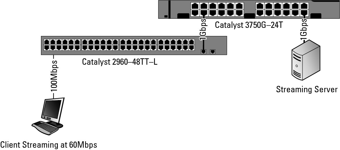
To show a connection deficit situation, I set up a Cisco 2960 switch (WS-C2960-48TT-L) with 48 Fast Ethernet (100 Mbps) ports, and two 1 Gigabit Ethernet copper ports, as well as a Cisco Catalyst 3750G switch (Catalyst 3750G-24T) with twenty-four 1 Gigabit Ethernet ports. During this example, I will adjust the load put on the switch by the client computers.
• In Figure 7-1, you see a network with a single client computer streaming data from a video server on a Gigabit Ethernet switch. Having one client on two expensive switches is not typical. When only one client streams the data, the client’s computer receives the data at a rate of 60 Mbps. Because a single client computer is on an unencumbered network, you can deduce that 60 Mbps is the maximum speed at which the application can receive data.
Figure 7-1: A client streaming data from a video server.
• Figure 7-2 shows a typical network, with 24 clients all streaming video from the server. In this situation, each client receives streamed data at approximately 33 Mbps (1000 Mbps uplink multiplied by 80 percent [network overhead] divided by 24 clients). This is the fastest speed at which clients could possibly get the data. With video streaming at a slower than maximum rate, clients may experience interruptions in their video playback.
• In Figure 7-3, a two-port EtherChannel group is enabled between the two switches, which doubles the bandwidth available on the uplink, bringing the link speed up to 2 Gbps. With the inter-switch link at 2 Gbps, the transfer rate for each client goes up to the maximum speed of 60 Mbps per client. To support all 48 clients at that rate, you need two more gigabit ports to add an EtherChannel group — not possible on this switch, but possible with a Cisco Catalyst 3750G switch, which has 48 gigabit ports.
Figure 7-2: A network of 24 clients streaming video from the server.

You are not limited to combining two ports. You can use EtherChannel to get up to eight active ports in a single channel group and up to six port groups on a switch. Later sections of this chapter walk you through the process of setting up these EtherChannel links.
Figure 7-3: Bandwidth deficits are possible on switches when load increases.

![]() In the introduction to this chapter, I say that EtherChannel comes with a cost. The cost is the loss of extra ports. If you have two 48-port gigabit switches, and you decide you need an 8 Gbps interconnect, you lose eight ports per switch, whereas you may have budgeted for only one port per switch based on your port counts for servers, and so on. Now your available device ports go from 94 host connections to 80 host connections.
In the introduction to this chapter, I say that EtherChannel comes with a cost. The cost is the loss of extra ports. If you have two 48-port gigabit switches, and you decide you need an 8 Gbps interconnect, you lose eight ports per switch, whereas you may have budgeted for only one port per switch based on your port counts for servers, and so on. Now your available device ports go from 94 host connections to 80 host connections.
Checking Out EtherChannel Basic Guidelines
Rules, rules, rules, everything in the networking world has rules! EtherChannel is no different; it has a set of restrictions that dictate what you can and cannot do. Before running off to implement EtherChannel, know what the restrictions are so you do not get halfway through and find out it will not work the way you planned. Here are some basic guidelines on setting up EtherChannel:
• You can assign up to eight ports to a channel group. Using Link Aggregation Control Protocol (LACP), you can configure 16 ports in the port group, but only eight ports can be active; the other ports are in Standby mode. This is useful when you lose links in the active group, as the standby links will activate immediately. If you happen to configure your ports this way, then you have a very fast, very reliable inter-switch link, with a very high port cost.
• You need to configure both switches for the same connection mode: Link Aggregation Control Protocol (LACP), Port Aggregation Protocol (PAgP), or EtherChannel.
• PAgP is a Cisco propriety protocol, whereas LACP is an open standard. If you are creating EtherChannel with switches from other vendors, you need to use LACP.
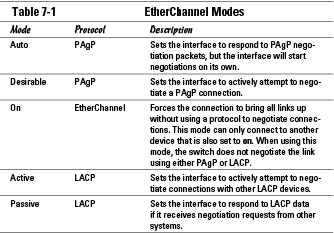
• PAgP has two configuration modes, Auto and Desirable. Auto waits for the other host to start the session, and Desirable attempts to start the session. The Auto setting will minimize the number of PAgP packets sent on the connection. An Auto-configured link can form a session with a Desirable-configured link; a Desirable can form a session with another Desirable-configured link or an Auto-configured link. However, both ends of an inter-switch link cannot be set to Auto, or you would have two hosts on Auto looking rather dumb waiting for each other to start the session.
• LACP also has two configuration modes, Active and Passive. Similar to PAgP’s Auto and Desirable, an Active link attempts to start a LACP session by sending out negotiation packets; a Passive link will respond to packets that it receives. As with Auto links in PAgP, the LACP Passive links minimizes the number of LACP packets sent on the connection. Both ends of the link cannot be set to Passive mode, so two Active links can form a session, as can an Active link and a Passive link, but two Passive links will never send out negotiation packets and again will just be standing around looking rather dumb.
• All ports in a channel group must have the same configuration for Speed and Duplex settings; otherwise, you have anarchy on your hands. Ports that are 100 Mbps Half Duplex trying to send data when the port they are paired with is a 1 Gbps Full Duplex port is like giving a German person coming to America a translator who only speaks Dutch and Russian.
• All ports must be assigned to the same VLAN and have matching switchport modes.
• When STP needs to send data out, it uses only one of the configured ports, instead of sending the data over all the ports.
Setting Up EtherChannel
When setting up an EtherChannel connection, remember the following points; they can help you avoid problems during the configuration process:
• You can configure up to eight ports, and all of these ports should be the same type (Fast Ethernet, Gigabit Ethernet).
• Set all ports to function at the same Speed and Duplex settings.
• Ensure that all ports are enabled and that none have been configured using the shutdown command. The shutdown command is discussed in Chapter 3 of this minibook.
• Switchport settings from the first port in EtherChannel are copied to all other ports in the EtherChannel when the ports are added to the channel group. This is a copy action and not a link, so if you change the settings after the fact, you need to change the settings on all ports. The settings that must remain the same across all ports are
• Allowed VLAN list
• STP path cost
• STP port priority
• STP PortFast settings
• EtherChannel groups
![]() Cisco’s GigaStack, FlexStack, and other proprietary high speed inter-switch links should never be configured as part of an EtherChannel because these stacking ports have specific functionality enabled for stacking functions that is not compatible with EtherChannel. Only use standard connection ports on the front of your switch for EtherChannel connections.
Cisco’s GigaStack, FlexStack, and other proprietary high speed inter-switch links should never be configured as part of an EtherChannel because these stacking ports have specific functionality enabled for stacking functions that is not compatible with EtherChannel. Only use standard connection ports on the front of your switch for EtherChannel connections.
Stepping through EtherChannel configuration
The basic process for configuring your EtherChannel interfaces is as follows:
1. Connect to the command-line interface (CLI) your switch.
As discussed in Book I, Chapter 5, this connection may be via SSH, Telnet, or the console port.
2. Access Privileged EXEC mode.
Switch1> enable
3. Access Global Configuration mode.
Switch1# configure terminal
4. Access Interface Configuration mode.
Switch1(config)# interface range fasttethernet0/11 -12
5. Change switchport to trunk or access, but all ports must be in the same VLAN.
Switch1(config-if-range)# switchport mode access
Switch1(config-if-range)# switchport access vlan 10
6. Assign the port to a channel group, which is an integer between 1 and 6. You also configure PAgP or LCAP at this time by specifying a mode, as listed in Table 7-1.
Switch1(config-if-range)# channel-group 5 mode desirable
7. Use the end command to exit out of Global Configuration mode.
The following commands are the setup commands you use for configuring one of the switches for EtherChannel. Notice the keyword “desirable,” which means that you will be using the Cisco proprietary protocol of PAgP. This also means that the switch at the other end of the connections needs to be a Cisco switch as well.
Switch1> enable
Switch1# configure terminal
Switch1(config)# interface range fasttethernet0/11 -12
Switch1(config-if-range)# switchport mode access
Switch1(config-if-range)# switchport access vlan 10
Switch1(config-if-range)# channel-group 5 mode desirable
Note that on the second switch, you applied the following configuration. Notice that the channel-group used on this switch is different. Different port groups are allowed because it is simply a local (to the switch) configuration to keep each port group uniquely identified. Many IT administrators do keep the channel-group numbers the same because by matching the port group numbers on either end of the connection, you can avoid confusion for others.
Switch2> enable
Switch2# configure terminal
Switch2(config)# interface range fasttethernet0/1 -2
Switch2(config-if-range)# switchport mode access
Switch2(config-if-range)# switchport access vlan 10
Switch2(config-if-range)# channel-group 2 mode auto
Switch2(config-if-range)# end
In this configuration, this pair of ports allows you to send data only for VLAN 10 over the EtherChannel link. To pass traffic for all VLANs, you must configure the switchport as a trunk because Access ports will only send traffic for one VLAN.
Configuring EtherChannel load balancing
EtherChannel can use two methods for load balancing connections, with the default load balancing based on the source MAC address of the system sending data. But because it is sometimes more important for some data to be received rather than sent, Cisco gives you a choice. The two methods you can use for load balancing are Source MAC (src-mac) and Destination MAC (dst-mac). So, what exactly does all this mean? When load balancing the connection, the switch takes a look at the MAC addresses in the packet header to determine which link is used for the data. In the src-mac mode (the default load balancing mode), the switch looks at the frame source MAC address, then it passes all frames it sees from the same source MAC address through one of the links. dst-mac works the same way, but it classifies the frames based on the destination and will always pass data from that MAC address through the same link. To configure load balancing, use the following commands:
Switch1> enable
Switch1# configure terminal
Switch1(config)# port-channel load-balance dst-mac
Switch1(config)# end
To view this setting, use the show command, as shown here:
Switch1> enable
Switch1# show etherchannel load-balance
Destination MAC address
Getting at Diagnostic Information for EtherChannel
To diagnose problems, you first must be able to collect information about your switch and its EtherChannel configuration. To perform this task, you, as always, rely on the show and debug commands. I start with a brief overview of what you get from the show command.
Switch1> enable
Switch1# configure terminal
Switch2#show EtherChannel ?
<1-6> Channel group number
detail Detail information
load-balance Load-balance/frame-distribution scheme among ports in
port-channel
port Port information
port-channel Port-channel information
protocol protocol enabled
summary One-line summary per channel-group
| Output modifiers
<cr>
Following the typical Cisco command standard, detail gives you more information than you probably want, whereas summary gives you little more than the basics. You should check with summary first, and if the information you need is there, then you are done; otherwise, load up the screen with information from the detail option. The other options for the show EtherChannel command give you more information about your ports, port-channels, and protocols (PAgP or LACP) if in your troubleshooting you feel that you need to drill down a little deeper. Here is the summary information for the current connection, which reveals the ports that make up the EtherChannel.
Switch1> enable
Switch1# configure terminal
Switch2#show etherchannel summary
Flags: D - down P - in port-channel
I - stand-alone s - suspended
H - Hot-standby (LACP only)
R - Layer3 S - Layer2
u - unsuitable for bundling
U - in use f - failed to allocate aggregator
d - default port
Number of channel-groups in use: 1
Number of aggregators: 1
Group Port-channel Protocol Ports
------+-------------+-----------+----------------------------------------------
2 Po2(SD) PAgP Fa0/1(D) Fa0/2(D)
In addition to the EtherChannel information, both PAgP and LACP offer further information via the show command. The information can be selected by channel group number and includes counters related to the data that has gone through the links, information about the links that is internal to the switch, and information about the devices on the other side of the EtherChannel links.
Switch1> enable
Switch1# configure terminal
Switch2#show PAgP ?
<1-6> Channel group number
counters Traffic information
internal Internal information
neighbor Neighbor information
Switch1> enable
Switch1# configure terminal
Switch2#show LACP ?
<1-6> Channel group number
counters Traffic information
internal Internal information
neighbor Neighbor information
sys-id LACP System ID
Here is an example of one of those commands, it is retrieving information about PAgP, using the internal option. You can see in the output that even though you configured the switch, one of the cables is not attached (flag is d), and as such, only half of the EtherChannel is up. With the second cable attached, you see both ports with the SC flags and the H timer running.
Switch2> enable
Switch2# show pagp internal
Flags: S - Device is sending Slow hello. C - Device is in Consistent state.
A - Device is in Auto mode. d - PAgP is down
Timers: H - Hello timer is running. Q - Quit timer is running.
S - Switching timer is running. I - Interface timer is running.
Channel group 2
Hello Partner PAgP Learning Group
Port Flags State Timers Interval Count Priority Method Ifindex
Fa0/1 SC U6/S7 H 30s 1 128 Any 15
Fa0/2 d U1/S1 1s 0 128 Any 0
Debugging EtherChannel
The basic debug command options are listed here. As always with the debug command, you can use specific options if you have an idea about where the issues are or can enable all of the debug options for the component — if doing so does not generate too much information.
Switch2#debug etherchannel ?
all All debugging
detail Step below all
error Displaying error messages
event Major events
idb Agport idb related events
linecard SCP messages to linecard
<cr>
Switch2> enable
Switch2#debug pagp ?
all PAgP all debugging
event PAgP events
fsm PAgP Finite State Machine
misc PAgP Miscellaneous
packet PAgP activity
<cr>
Switch2> enable
Switch2#debug lacp ?
all LACP all debugging
event LACP events
fsm LACP Finite State Machine
misc LACP Miscellaneous
packet LACP activity
<cr>
In this case, both the EtherChannel and PAgP debug commands are enabled, but not LACP because you do not expect to see any LACP information on the network. Previously in this chapter, only PAgP was enabled, so if you see LACP data, something is seriously wrong. In the production network, where someone else may be configuring the remote end of the connection, it may not hurt to turn on the LACP option as well. Notice in the output that the interface is brought up.
Switch2> enable
Switch2# debug EtherChannel
Switch2# debug PAgP
3d01h: %LINK-3-UPDOWN: Interface FastEthernet0/1, changed state to up
3d01h: FEC: pagp_switch_agc_compatable: comparing GC values of Fa0/1 Po5 flag = 1 1
3d01h: FEC: pagp_switch_port_attrib_diff: Fa0/1 Po5 same
3d01h: FEC: pagp_switch_agc_compatable: GC values are compatable
3d01h: PAgP - Fa0/1 failed - not my device_id. 0000.0000.0000 0006.d6ac.46c0
3d01h: FEC: add port (Fa0/1) to agport (Po5)
3d01h: FEC: pagp_switch_add_port_to_agport_internal: msg to PM to bundle port Fa0/1 with Po5
3d01h: FEC: pagp_switch_want_to_bundle: Bndl msg to PM for port Fa0/1 to Agport Po5
3d01h: %LINEPROTO-5-UPDOWN: Line protocol on Interface FastEthernet0/1, changed state to up
3d01h: %LINK-3-UPDOWN: Interface Port-channel5, changed state to up
3d01h: %LINEPROTO-5-UPDOWN: Line protocol on Interface Port-channel5, changed state to up