
Chapter 5: Getting into the Cisco Internetwork Operating System
In This Chapter
![]() Navigating the operational modes like a pro
Navigating the operational modes like a pro
![]() Connecting your devices
Connecting your devices
![]() Managing the IOS image and the boot process
Managing the IOS image and the boot process
Although each type of Cisco product (such as switches, routers, or firewalls) has its own way of doing things, you see some common features or functions across much of the product line, such as assigning an Internet Protocol (IP) address to the device. Even within a product line, you may see a difference between specific devices, such as configuration commands between high-end and low-end switches.
Although several differences exist between some products, this chapter focuses on the items that are common across most of the enterprise-level devices. Here I show you the core features of the Internetwork Operating System (IOS) and how to make management connections to most Cisco devices.
![]() As you move through the rest of this book (specifically Book III onward), you put this information to work in managing your Cisco devices.
As you move through the rest of this book (specifically Book III onward), you put this information to work in managing your Cisco devices.
This chapter starts pretty easily, but as with most work in the networking world, it gets a little heavy near the end. By the end though, you have a good understanding as to what the Cisco IOS is and how to navigate within it. I end this chapter with a few items, such as choosing a boot image and upgrading the IOS, that you need only to deal with periodically. However, this information aids in your understanding of the startup and operating process.
Working with the Internetwork Operating System
The Cisco IOS is often imitated, but thanks to a very strong legal department, not yet duplicated. The Internetwork Operating System is the core engine on Cisco routers, switches, and firewalls. The IOS is small, fast, and efficient; it carries out all tasks on these devices — just like the operating system on your computer makes the computing hardware perform your required actions.
All enterprise-level devices — routers, switches, and firewalls — share a similar IOS. The IOS software runs the different Cisco hardware platforms and provides different services or functions depending on the version of the software used. For instance, the Network Address Translation (NAT) was introduced into the Cisco IOS in version 11.3, so to make use of specific features, you will often require a specific version of the Cisco IOS.
Checking out the show command
Although routers, switches, and firewalls all have unique functions and the IOS will have different commands to support these functions, the IOS uses several core commands on all these devices.
![]() At the start of this chapter, I really want you to review what I am doing, but not follow along with your own equipment just yet. In the later section, “Tinkering with Device Connections,” I show you how to get a management connection established to your Cisco network device, but it helps to be familiar with some of the management interface operations before you get that connection. After you make the management connection to your own device, you may want to review this section. You also find information about connecting the management interface of switches and routers in Book III and Book IV, respectively. If you are planning to work through some of the examples in this chapter with a Cisco switch, then read Book III, Chapter 3 to learn how to get a management connection to the console port on the switch. If you are planning to use a router, then read Book IV, Chapter 3.
At the start of this chapter, I really want you to review what I am doing, but not follow along with your own equipment just yet. In the later section, “Tinkering with Device Connections,” I show you how to get a management connection established to your Cisco network device, but it helps to be familiar with some of the management interface operations before you get that connection. After you make the management connection to your own device, you may want to review this section. You also find information about connecting the management interface of switches and routers in Book III and Book IV, respectively. If you are planning to work through some of the examples in this chapter with a Cisco switch, then read Book III, Chapter 3 to learn how to get a management connection to the console port on the switch. If you are planning to use a router, then read Book IV, Chapter 3.
In this section, you examine the show version command. The show version command displays slightly different information depending on the type of device you use it on, whether that is a switch, router, or firewall. You look at the output of the show version command on all three of these device types. The goal of this section is to enforce the point that commands you use may not be exactly the same on each type of device.
![]() Although I have said the command is
Although I have said the command is show version, technically it is the show command and version is an option.
Examining show version on a switch
As I mention earlier, in order to type the show version command yourself, you need to have a connection to the management interface of your switch. You can skip ahead to the “Tinkering with Device Connections” section to find out how to do this. Here, I want to show the difference in command operations between device types.
Look at the output of the show version command on a switch and take note of the following information:
• IOS version
• System uptime
• Image filename
• Type of processor
• Amount of RAM
• Number of ports on the switch
• Amount of flash memory
• MAC address
• Serial number
The management interface that you use is the console connection. This connection is made through the Console port on the device using the blue rollover cable that came with your device. After making the connection, you use a terminal emulator program (such as PuTTY) to see what is going on with the device. I cover this later in the chapter in the section, “Connecting directly via a Cisco rollover cable.”
![]() Through this book, you see code examples like the following one. In this example, you see that some of the text is bold. The full example shows what is taking place in a console screen using the Cisco CLI, while the bold text shows what was typed.
Through this book, you see code examples like the following one. In this example, you see that some of the text is bold. The full example shows what is taking place in a console screen using the Cisco CLI, while the bold text shows what was typed.
Here is a copy of what the show version command shows for my switch:
Switch>show version
Cisco Internetwork Operating System Software
IOS (tm) C2950 Software (C2950-I6Q4L2-M), Version 12.1(22)EA13, RELEASE SOFTWARE (fc2)
Technical Support: http://www.cisco.com/techsupport
Copyright (c) 1986-2009 by cisco Systems, Inc.
Compiled Fri 27-Feb-09 22:20 by amvarma
Image text-base: 0x80010000, data-base: 0x80570000
ROM: Bootstrap program is C2950 boot loader
Switch uptime is 0 minutes
System returned to ROM by power-on
System image file is “flash:c2950-i6q4l2-mz.121-22.EA13.bin”
cisco WS-C2950-12 (RC32300) processor (revision B0) with 20957K bytes of memory.
Processor board ID FAB0535Q22L
Last reset from system-reset
Running Standard Image
12 FastEthernet/IEEE 802.3 interface(s)
32K bytes of flash-simulated non-volatile configuration memory.
Base ethernet MAC Address: 00:06:D6:AB:A0:40
Motherboard assembly number: 73-5782-08
Motherboard serial number: FAB0535BC1K
Model revision number: B0
Model number: WS-C2950-12
System serial number: FAB0535Q22L
Configuration register is 0xF
Examining show version on a router
Review the output of the show version command on a router and try to locate the following information. The output gives you insight into the router’s capabilities, and overall gives you practice reading the output of many Cisco commands:
• IOS version
• System uptime
• Image filename
• Type of processor
• Amount of RAM
• Number of ports on the switch
• Amount of flash memory
• Current configuration register
Here is what the show version command displays for one of my routers:
Router1#show version
Cisco IOS Software, C2600 Software (C2600-ADVIPSERVICESK9-M), Version 12.3(4)T4, RELEASE SOFTWARE (fc2)
Technical Support: http://www.cisco.com/techsupport
Copyright (c) 1986-2004 by Cisco Systems, Inc.
Compiled Thu 11-Mar-04 19:57 by eaarmas
ROM: System Bootstrap, Version 12.2(8r) [cmong 8r], RELEASE SOFTWARE (fc1)
Router1 uptime is 20 minutes
System returned to ROM by power-on
System image file is “flash:c2600-advipservicesk9-mz.123-4.T4.bin”
This product contains cryptographic features and is subject to United
States and local country laws governing import, export, transfer and
use. Delivery of Cisco cryptographic products does not imply
third-party authority to import, export, distribute or use encryption.
Importers, exporters, distributors and users are responsible for
compliance with U.S. and local country laws. By using this product you
agree to comply with applicable laws and regulations. If you are unable
to comply with U.S. and local laws, return this product immediately.
A summary of U.S. laws governing Cisco cryptographic products may be found at:
http://www.cisco.com/wwl/export/crypto/tool/stqrg.html
If you require further assistance please contact us by sending email to
Cisco 2621XM (MPC860P) processor (revision 0x300) with 125952K/5120K bytes of memory.
Processor board ID JAE081160XR (3618058385)
M860 processor: part number 5, mask 2
2 FastEthernet interfaces
1 Virtual Private Network (VPN) Module
32K bytes of NVRAM.
32768K bytes of processor board System flash (Read/Write)
Configuration register is 0x2102
Examining show version on the Cisco ASA firewall
Look at the output of the show version command on an Adaptive Security Appliance (ASA) and take note of the following information, as you have with the previous devices:
• IOS version
• Name of the image file
• System uptime
• Type of processor and hardware platform
• Amount of RAM
• Amount of flash memory
• MAC address
• Number of ports on the switch
• Licensed features
• Serial number
• Current configuration register
Here is what the show version command displays for my ASA:
ciscoasa> show version
Cisco Adaptive Security Appliance Software Version 8.2(1)11
Device Manager Version 6.2(3)
Compiled on Mon 21-Sep-09 17:47 by builders
System image file is “disk0:/asa821-11-k8.bin”
Config file at boot was “startup-config”
ciscoasa up 28 mins 4 secs
Hardware: ASA5505, 256 MB RAM, CPU Geode 500 MHz
Internal ATA Compact Flash, 128MB
BIOS Flash M50FW080 @ 0xffe00000, 1024KB
Encryption hardware device : Cisco ASA-5505 on-board accelerator (revision 0x0)
Boot microcode : CN1000-MC-BOOT-2.00
SSL/IKE microcode: CNLite-MC-SSLm-PLUS-2.03
IPSec microcode : CNlite-MC-IPSECm-MAIN-2.04
0: Int: Internal-Data0/0 : address is 001f.ca8c.93da, irq 11
1: Ext: Ethernet0/0 : address is 001f.ca8c.93d2, irq 255
2: Ext: Ethernet0/1 : address is 001f.ca8c.93d3, irq 255
3: Ext: Ethernet0/2 : address is 001f.ca8c.93d4, irq 255
4: Ext: Ethernet0/3 : address is 001f.ca8c.93d5, irq 255
5: Ext: Ethernet0/4 : address is 001f.ca8c.93d6, irq 255
6: Ext: Ethernet0/5 : address is 001f.ca8c.93d7, irq 255
7: Ext: Ethernet0/6 : address is 001f.ca8c.93d8, irq 255
8: Ext: Ethernet0/7 : address is 001f.ca8c.93d9, irq 255
9: Int: Internal-Data0/1 : address is 0000.0003.0002, irq 255
10: Int: Not used : irq 255
11: Int: Not used : irq 255
Licensed features for this platform:
Maximum Physical Interfaces : 8
VLANs : 20, DMZ Unrestricted
Inside Hosts : Unlimited
Failover : Active/Standby
VPN-DES : Enabled
VPN-3DES-AES : Enabled
SSL VPN Peers : 2
Total VPN Peers : 25
Dual ISPs : Enabled
VLAN Trunk Ports : 8
Shared License : Disabled
AnyConnect for Mobile : Disabled
AnyConnect for Cisco VPN Phone : Disabled
AnyConnect Essentials : Disabled
Advanced Endpoint Assessment : Disabled
UC Phone Proxy Sessions : 2
Total UC Proxy Sessions : 2
Botnet Traffic Filter : Disabled
This platform has an ASA 5505 Security Plus license.
Serial Number: JMX1214Z0LF
Running Activation Key: 0xe6135258 0xe84c9b0d 0x6c501544 0x90d4f8d0 0x400ab69d
Configuration register is 0x1
Configuration has not been modified since last system restart.
The base IOS feature set is the same across these three device platforms (switches, routers, and ASA firewalls), so in addition to a core block of information, each product line has some unique information that is returned by the show version command. For example, the firewall returned licensing information regarding the number of SSL VPN Peers that are supported. This number represents the number of client Virtual Private Network (VPN) connections that the ASA is licensed for when using secure HTTP over Secure Sockets Layer (SSL).
Understanding operating modes
Regardless of the device that you are configuring, there are a few standard but distinct modes or styles of the command prompt. You get to those command prompts using a cable, Secure Shell (SSH), or Telnet connection. Each prompt serves a purpose, so you need to become familiar with them and understand what you can do at the prompts. The prompt itself is the indicator of the operating system mode, and it is the operating system mode that determines what commands you are allowed to use.
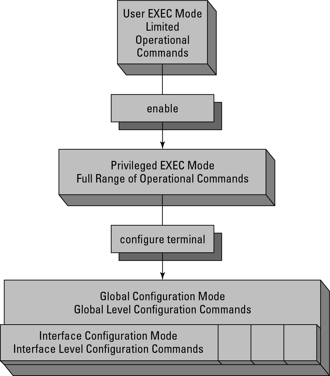
The Cisco IOS has an escalating set of permissions as you move through the prompts or operating modes. When you first connect to a device you will be in User EXEC mode; then by issuing the enable command you are brought to Privileged EXEC mode; by issuing the configure terminal command you will be brought to Global Configuration mode; finally, by issuing one of any number of other commands you will be brought to an interface or sub-configuration mode. I point out when these other modes show up, but they would be too lengthy and boring to list them all here. Figure 5-1 graphically shows the escalation among these commands.
User EXEC mode
When you first connect to a router, switch, or firewall, you see an initial prompt that looks like the following (but bear in mind that it could say switch or firewall as well):
Router>
The text in the prompt represents the hostname of the device, which by default is the device type; but you may have already renamed your devices, in which case it could now be anything. The greater-than (>) sign denotes that you are in User EXEC mode, or User EXECute mode. This mode has only a few commands that you can execute, including the following, and these are commands that you should find in all devices, be they routers, switches, or firewalls:
Figure 5-1: Command operating modes.
• connect: Opens a terminal session to another switch or router.
• disconnect: Closes a session that was opened from a remote switch or router.
• enable: Enters Privileged EXEC mode or enables privileged commands.
• ping: Sends ping or Internet Control Message Protocol (ICMP) echo request packets to a remote IP host, which could be a switch or router. You read more on this command in Book II, Chapter 3.
• show: Displays configuration information. The information that can be viewed at this level is very limited.
• systat: Displays information regarding management connections.
• telnet: Opens a Telnet connection to a remote device, which could be a router or switch.
• traceroute: Traces a route to a destination displaying connectivity results along the path. You read more on this command in Book II, Chapter 3.
This limited command set does not allow you to do very much on the system itself, which is good because you can get to this mode without a password. To get to the real command set, enter Privileged EXEC mode, which by default has a password restricting access.
Privileged EXEC mode
User EXEC mode allows you to do only some very basic commands, whereas if you want to really have access to the system, you need to use Privileged EXEC mode. To enter this mode, run the enable command, which prompts you for a password, if configured. As the mode name suggests, this mode has extra privileges to allow you to make major changes to the system or to enter Configuration mode. When you are in Privileged EXEC mode, your command prompt resembles the following (this is the hostname, which by default is the name of the device, but could be anything else):
Router#
The hash/pound sign (#) denotes that you are in the Privileged EXEC mode. Some of the commands that are available include these commands that you should find in all devices, be they routers, switches, or firewalls
• cd: Change the current directory. Routers and switches have several file systems, including flash, nvram, system, and null.
• clear: Resets functions operating on the device. There are many values that are totaled for reporting that can be reset this way. You can also reset many system-wide configuration values.
• clock: Allows you to change the system clock.
• copy: Copy a file from one location to another. The location could be another local file system or a remote file system, such as a Trivial File Transfer Protocol (TFTP) server.
• debug: Turn on debug logging. This can be done for a specific interface or software component, or for all functions. This places a load on the device if the debugging level is too high and generates an incredible level of messaging on the console screen.
• delete: Removes a file from a file system.
• dir: Displays the list of files in the current directory.
• disable: Reverts the current session back to User EXEC mode and disables the privileged commands.
• erase: Removes all files in a file system. This is similar to an OS-level format command.
• exit: Exits from Privileged EXEC mode.
• no: Reverses a previously issued command. For example, debug all turns on all possible debugging, whereas no debug all turns off all possible debugging. Just about every command that can be issued can be reversed with the no command.
• ping: Sends ping or ICMP echo request packets to a remote IP host, such as a switch or router.
• pwd: Displays what the current file system directory is.
• reload: Restarts the device. This restart can be immediate or scheduled for the future. The reload command can also be used to cancel a scheduled reload.
• send: Sends a message to specific or all connected users. This is useful if you are about to perform certain maintenance tasks, such as rebooting the device.
• show: Displays configuration information. This is typically configuration information that is running, but it could also be used to view the startup configuration.
• systat: Displays information regarding management connections to this device.
• telnet: Opens a Telnet connection to a remote device, such as a router or switch.
• test: Tests subsystems, memory, and interfaces as part of your diagnostic or troubleshooting process.
• traceroute: Traces a route to a destination displaying connectivity results along the path.
• undebug: Disables debug commands that were set. This is an alternative to using the no command to perform these functions.
• write: Copies information in the running-config buffer to another location, such as memory, a TFTP server, or to the virtual terminal (vty) or console connection.
Global Configuration mode
When you type the configure command, you need to specify how you will make configuration changes. The most common manner of configuring devices is by using the terminal, so you use the configure terminal or conf t (for configure terminal) commands. The Global Configuration mode appears, and your command prompt will look something like this:
Router(config)#
This prompt is identified by the (config), which is in the prompt. You also have a different list of commands that you can type. Here is just a sample of the commands at this level:
• access-list: Manage Access Control Lists (ACLs) to restrict network connections to, from, or through the device you are connected to.
• arp: Manage the Address Resolution Protocol (ARP) cache on the device you are connected to.
• banner: Set a logon banner to issue a security warning to users connecting to the device you are connected to.
• boot: Configure or modify the system boot parameters, such as the IOS version that will be used.
• cdp: Cisco Discovery Protocol (CDP) tells you what is connected to you on network interfaces. CDP allows you to view this information.
• clock: Allows you to change the system clock.
• config-register (router only): Set the configuration register, which is the location in memory that stores a pointer to the system configuration information.
• enable: Sets or changes enable passwords.
• exit: Exits Global Configuration mode.
• hostname: Sets the device hostname.
• ip: Enters the IP configuration subcommands.
• interface: Selects an interface for configuration.
• no: Negates another command that has been issued.
• prompt: Sets the devices command prompt.
Interface Configuration Mode
In many cases when you are working with Global Configuration mode, you enter an interface for configuration or any number of subconfiguration modes. At that point in time, any commands you type apply only to the interface. When you are in Interface Configuration mode, your prompt looks something like this, while other configuration prompts will vary slightly in the displayed text:
Router(configure-if)#
Each interface or subconfiguration mode has its own list of configuration commands. Here are some of the commands that you see on a network interface:
• arp: Sets an interface ARP type or timeout.
• cdp: Configures CDP for a specific interface.
• delay: Specifies the delay on interface throughput. This is useful for limiting throughput or for simulating slower connections in a lab.
• description: Sets a descriptive name for the interface.
• exit: Exits Interface mode and returns to Configuration mode.
• ip: Configures IP protocol on the interface.
• logging: Configures logging for the interface.
• media-type: Chooses a media type for interfaces that have the option.
• mtu: Sets the interface maximum transmission unit (MTU), which limits the size of the Ethernet frame.
• no: Negates other commands that have been issued.
• shutdown: Disables or shuts down the interface.
Type the exit command to leave a mode and move to the next higher mode. You need to do that if the commands you want to use do not work at that level. For example, to view the current configuration that is in use, use the show running-configuration command. That command can be used only in Privileged EXEC mode, so if you are in Global Configuration mode, you need to move one level up to use that command. If after viewing the running configuration, you decide that you need to change the IP address of the Fast/Ethernet0/0 interface of a router, you need to use a sequence like this (do not worry about the actual commands at this point, I only want you to see and understand how to move between the command modes):
Router#configure terminal
Enter configuration commands, one per line. End with CNTL/Z.
Router(config)#interface FastEthernet 0/0
Router(config-if)#ip address 192.168.1.2 255.255.255.0
Router(config-if)#exit
Router(config)#exit
Router#
Saving your work
After you are happy with your configuration, you can save it. Your configuration is stored in two main locations: One is in RAM, and the other is in the configuration that is in use, or the running configuration. When you type commands, those commands are activated immediately and are stored in the running configuration, which is stored in RAM. Therefore, when the power is turned off, the configuration is lost. To save that configuration, copy it to the startup configuration, which means it is stored in non-volatile RAM (NVRAM), so that the configuration is retained when you turn off the power.
You can use two commands to save your configuration, the write command or the copy command. The write command is deprecated, but would look like this
Router#write memory
Building configuration...
[OK]
The newer version of the command is the copy command, which looks like
Router#copy running-config startup-config
Destination filename [startup-config]?
Building configuration...
[OK]
The deprecated command is short and single-purposed, not flexible with full options like the newer command.
For any command you only have to type as many letters as the IOS requires to uniquely identify the command. So you will find that a lot of old-timers use the following command as a reflex after they complete changes and when they exit Global Configuration mode to copy their current running-config to the startup-config:
wri mem
The copy command offers more flexibility and options. Not only can you copy the running configuration data to the startup configuration file, but you could copy it to a file on flash or to a TFTP server on your network. The copy command is only a little more to type:
copy run sta
Getting going with the command line
If you have followed along so far in this chapter, you are connected to the Cisco device and have a console connection open. You are now staring at this friendly command prompt, or something similar:
Router>
So now what? Well, you can ask the IOS for help. Type a question mark after Router>, and the IOS displays a list of commands that are possible at that level.
Router>?
EXEC commands:
access-enable Create a temporary Access-List entry
access-profile Apply user-profile to interface
clear Reset functions
connect Open a terminal connection
crypto Crypto
disable Turn off privileged commands
disconnect Disconnect an existing network connection
enable Turn on privileged commands
exit Exit from the EXEC
help Description of the interactive help system
lock Lock the terminal
login Log in as a particular user
logout Exit from the EXEC
modemui Start a modem-like user interface
mrinfo Request neighbor and version information from a multicast
router
mstat Show statistics after multiple multicast traceroutes
mtrace Trace reverse multicast path from destination to source
name-connection Name an existing network connection
pad Open a X.29 PAD connection
ping Send echo messages
--More-
When the --More- text is displayed at the bottom of a page (see the preceding code), you can press Enter to advance the list by one line or press the spacebar to advance by one screen. If you prefer to start typing one of the commands, you can hit just about any key to exit from the --More- listing and type your command.
Other times you may start typing the letters of a command but you cannot remember what the actual command is. Anytime you type the command, you can add a question mark to the end of it to see what commands could be completed. Here is an example in Privileged EXEC mode:
Router#c?
call ccm-manager cd clear
clock cns configure connect
copy crypto
Getting a command’s options
The Cisco IOS has a great context-sensitive Help function, which means the IOS can help you find the specific item you are currently working with. To start using Help, you need to type a command in the CLI. After you type one command, you can ask the IOS for help with possible options for that command. After you type your selected command, type a space and a question mark to get a list of options for that command. For example, running the copy command with the question mark results in the following:
Router#copy ?
/erase Erase destination file system.
/noverify Don’t verify image signature before reload.
/verify Verify image signature before reload.
cns: Copy from cns: file system
flash: Copy from flash: file system
ftp: Copy from ftp: file system
http: Copy from http: file system
https: Copy from https: file system
null: Copy from null: file system
nvram: Copy from nvram: file system
pram: Copy from pram: file system
rcp: Copy from rcp: file system
running-config Copy from current system configuration
scp: Copy from scp: file system
startup-config Copy from startup configuration
system: Copy from system: file system
tftp: Copy from tftp: file system
![]() In fact, if you have not typed anything on the CLI, you can still type the question mark to get a list of all the available commands that you can use from your current mode. This is a very long list, so if you start with the first few letters of the command, you will greatly reduce the size of the list.
In fact, if you have not typed anything on the CLI, you can still type the question mark to get a list of all the available commands that you can use from your current mode. This is a very long list, so if you start with the first few letters of the command, you will greatly reduce the size of the list.
Autocomplete
If you would rather not type the complete command, use the command completion option. If you have to type enough letters of the command that the IOS knows it is unique, you do not have to type anything else; or you can press the Tab key to complete the word you are typing. I prefer pressing the Tab key because it saves me from making a typo. If you are not sure what options you can choose, add a question mark to the end.
In this example, I pressed Tab at the end of each line prior to typing the question mark, which completed each word of the command. Finally, I typed the question mark to see the options with my final command, the only option available is carriage return (<cr>), which means just pressing the Enter key on your keyboard.
Router#cop
Router#copy run
Router#copy running-config sta
Router#copy running-config startup-config ?
<cr>
Using the command buffer
If you type the same commands again and again, you can make use of the command buffer, or terminal history. By default the command buffer holds ten lines, but it can be reconfigured with the Privileged EXEC mode terminal history size 10 command. To see the contents of the buffer, use the following command:
Router(config)#do show history
hostname Router
int fastEthernet 0/0
ip address 192.168.1.2 255.255.255.0
exit
int fastEthernet 0/1
ip address 10.0.0.1 255.0.0.0
exit
do show history
The Privileged EXEC mode and Global Configuration mode each have their own command buffers, so if you make configuration changes and want to see them, use the do command. Remember, show is not an available command in Global Configuration mode. Instead, use the do command to tell the IOS to run the show command from Privileged EXEC mode rather than Global Configuration mode. There are only a few Privileged EXEC mode commands that you can run with the do command.
If you see a command in the command buffer that you want to run again, you can copy and paste it back into your terminal application. This process varies depending on the application you use. Later in this chapter, I review the PuTTY application, which is available for both Windows and Linux.
![]() You can quickly review what commands are in the terminal buffer by using the up- or down-arrow key on your keyboard. Use the up-arrow key to scroll through your last commands; if you go too far, use the down-arrow key to go back.
You can quickly review what commands are in the terminal buffer by using the up- or down-arrow key on your keyboard. Use the up-arrow key to scroll through your last commands; if you go too far, use the down-arrow key to go back.
Tinkering with Device Connections
Before you can make your configuration changes, you need to get a connection to your router or switch. The two basic methods of connecting to your device are either directly via a Cisco rollover cable or remotely via a Telnet or SSH connection. The following sections take a closer look at both methods.
Connecting directly via a Cisco rollover cable
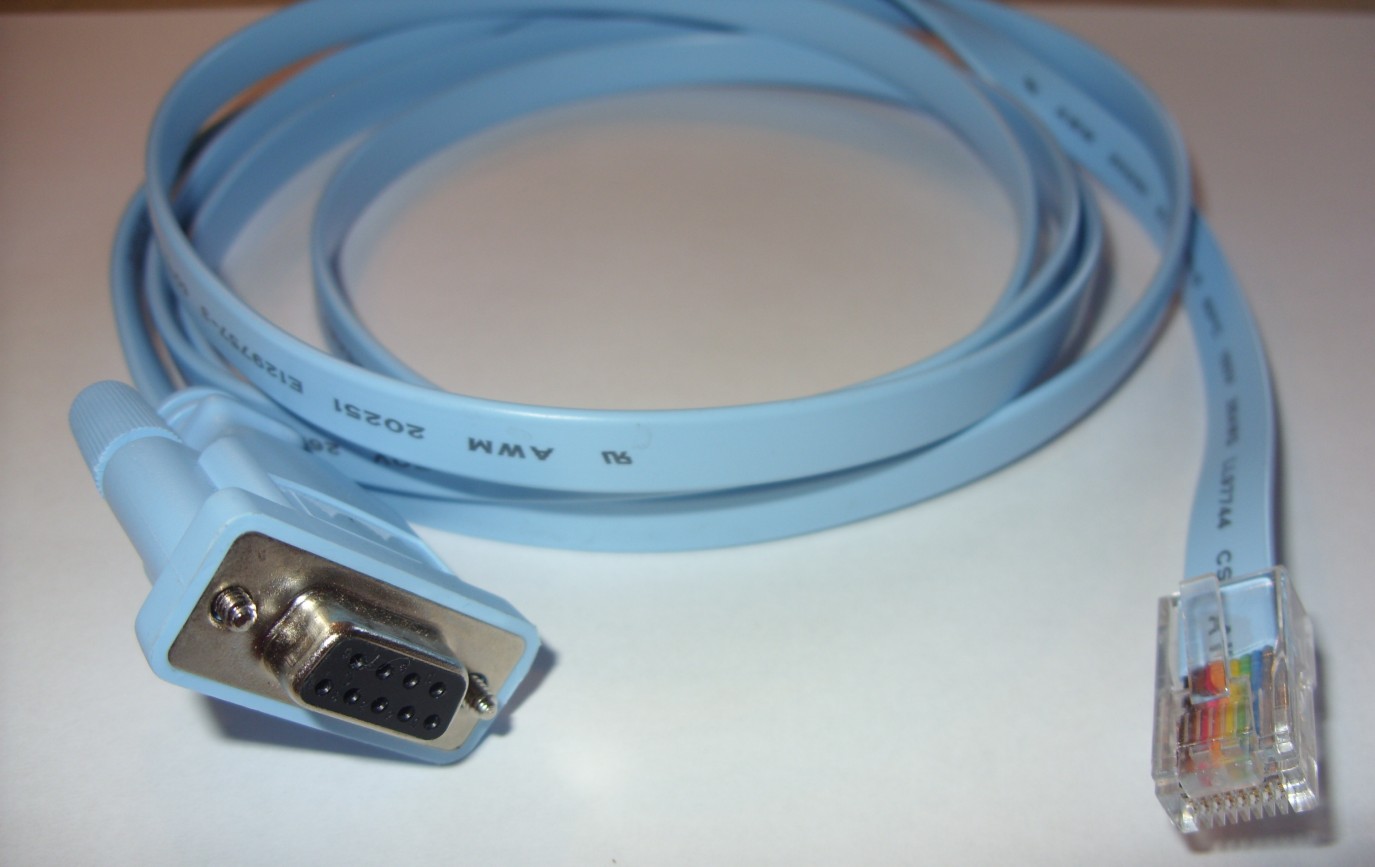
You most likely make your initial configuration of your Cisco device through a direct serial cable connection via a Cisco rollover cable — the strange blue cable you get with each of your managed devices, as shown in Figure 5-2. (You can purchase unmanaged switches, which do not include the cable or the ability to perform any configuration management. I do not discuss unmanaged switches in this book because there is you do not configure them.) Some of the Cisco Small Business lines have only web configuration options, which I discuss later in this chapter in the “Graphical Configuration Interfaces” section.
Figure 5-2: A Cisco rollover cable.
To use this cable, you need to have a 9-pin serial port on your computer; otherwise, you need to use an adapter. These days, many laptops and desktop computers are legacy-free; they do not have any legacy computer ports. This includes PS/2 keyboard and mouse ports, parallel ports, or serial ports. This can slow you down a bit when trying to configure your Cisco device. Luckily, a large market for manufacturers of USB adapters, such as the serial adapter shown in Figure 5-3, exists.
![]() Not all adapters are created equally, and I have had adapters that have not worked with some devices. Get a good price, but do not go cheap. To some degree, you do get what you pay for.
Not all adapters are created equally, and I have had adapters that have not worked with some devices. Get a good price, but do not go cheap. To some degree, you do get what you pay for.
Figure 5-3:
An aftermarket USB/serial port adapter.

After you have a place on your computer to connect the cable, look on the device for the console port. On most Cisco devices, this is blue and labeled RJ-45 connector, as shown in Figure 5-4. If this is a 9-pin serial connector, you are dealing with a very old device.
Figure 5-4: Console/serial port on your Cisco device.

Connect your computer to the console port on your Cisco device, which may even already be running. The next, and last, piece of the puzzle is a terminal emulator application.
![]() Some people use Microsoft HyperTerminal. However, I have always found this application confusing. To get a simple terminal connection, you need to create a dialup connection. HyperTerminal has been removed from the latest versions of Windows anyway, so you would still need to look for an alternative. As an alternative, therefore, I suggest either Tera Term (
Some people use Microsoft HyperTerminal. However, I have always found this application confusing. To get a simple terminal connection, you need to create a dialup connection. HyperTerminal has been removed from the latest versions of Windows anyway, so you would still need to look for an alternative. As an alternative, therefore, I suggest either Tera Term (http://hp.vector.co.jp/authors/VA002416/teraterm.html) or PuTTy (www.chiark.greenend.org.uk/~sgtatham/PuTTY). Both are free applications, but PuTTY is still actively supported and developed (well, the last update was 2007, but that is better than 1998).
If you choose to download PuTTY, you have many programs to choose from on the download page, such as
• PuTTY: The Telnet and SSH client itself
• PSCP: A Secure Copy Protocol (SCP) client, such as command-line secure file copy
• PSFTP: A Secure File Transfer Protocol (SFTP) client, such as general file transfer sessions like FTP
• PuTTYtel: A Telnet-only client
• Plink: A command-line interface to the PuTTY back ends
• Pageant: An SSH authentication agent for PuTTY, PSCP, and Plink
• PuTTYgen: An RSA (Rivest, Shamir, and Adleman) and DSA (Digital Signature Algorithm) key generation utility
If you want to use PuTTY to make a terminal connection to your Cisco device, choose the full version of PuTTY, which is the first item on the list.
To make life easy, copy the PuTTY.exe file and paste it directly to your Windows folder (C:Windows). This allows you to launch PuTTY by choosing the Windows Start menu⇒Run, as shown in Figure 5-5. In addition to making PuTTY easy to launch, after you have configured and saved a session, you can launch PuTTY and load a session automatically by using the PuTTY.exe -load COM command, which I discuss shortly.
Depending on the security settings on your version of Windows, you may be asked for confirmation to launch the application. For instance, Windows XP wants permission but you can change the setting so that you are not prompted in the future, as shown in Figure 5-6. As with all programs you download from the Internet, perform a virus scan to ensure that there are not any known issues with the application.
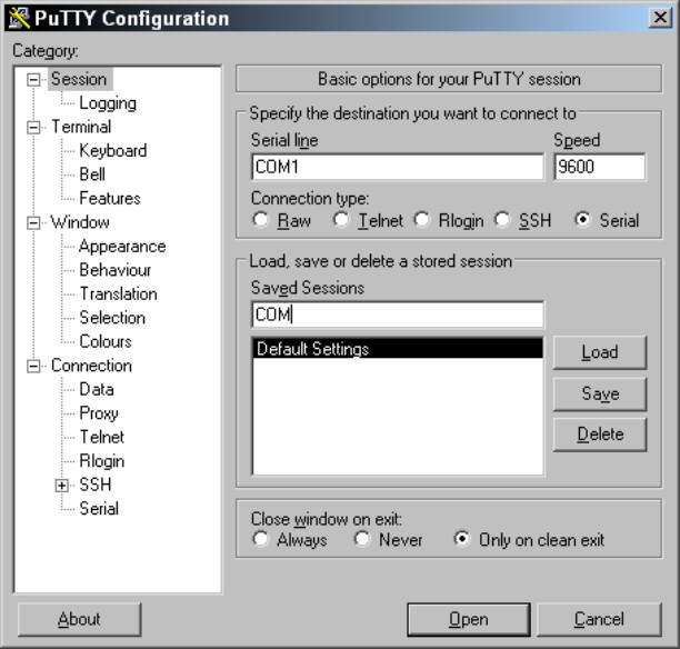
After PuTTY opens, the standard PuTTY Configuration dialog box appears. You can fill in your configuration settings and then click the Open button to make the connection, which opens a command window. If you regularly make connections to that device, save your settings by providing a session name and clicking the Save button. Figure 5-7 shows the session being saved for a serial connection through COM1 running at 9600 bps. After you save this connection, you can launch it automatically, as I mention earlier, by using PuTTY.exe -load COM from the Run dialog box. In most cases, you want to save sessions for your most used connections.
Figure 5-5: Launching PuTTY.exe from the Windows Start menu.

Figure 5-6: Windows security settings may prevent PuTTY.exe from launching auto-matically.
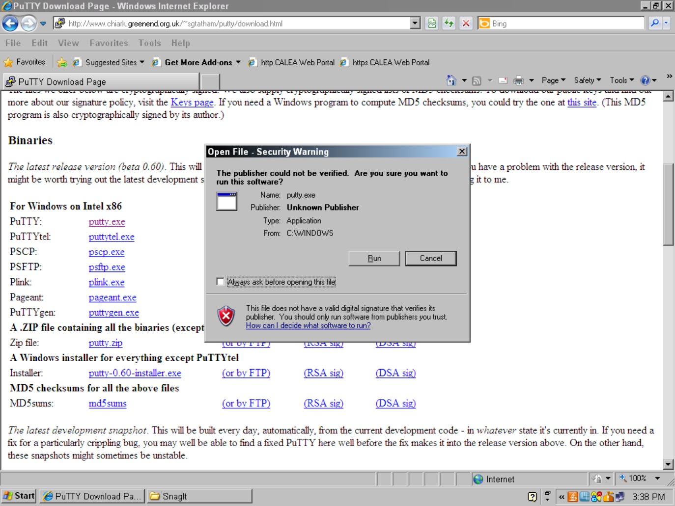
Figure 5-7: Saving a PuTTY connection session.
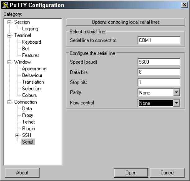
The settings you just saved work for most Cisco devices, but the actual recommended settings include a small adjustment in the PuTTY Configuration dialog box, as shown in Figure 5-8. These settings are a little slower than the default settings in PuTTY, so if your command window does not show the console data correctly, use these settings. Choose Connection⇒Serial in the left navigation pane, and put in matching configurations for
• Connection Speed: 9600 bps
• Data Bits: 8
• Stop Bits: 1
• Parity: None
• Flow Control: None
Figure 5-8: Specific recom-mended Cisco COM settings.
The last locally attached way to configure your Cisco router is with a modem. By using your Cisco rollover cable and a modem adapter, you can attach a modem directly to the console port. This configuration allows you to dial in to the Cisco device through the modem to make configuration changes. This is very old school in the Internet age, but it does allow you to either have a back door into the configuration in case your service provider or other link is down, or to provide enhanced security by disabling Telnet, SSH, and HTTPS connections directly into the firewall, router, or switch (although this would be more common with the first two devices).
Connecting remotely via Telnet or SSH
A console cable is fine for managing a couple of devices if you are physically close to them or if you have a console server that can be connected directly to all the devices that you have; but this is not normally the case. Typically, you configure your devices, and then deploy them to different locations in your organization or you may move to a location where you are not physically close to the devices. What then? Well, you need a remote method of connecting to your devices.
Telnet
For years, Telnet has been the industry standard. Telnet gives you terminal access to your devices over an IP network. This functionality has been built into every router and managed switch that have been sold for decades; but Telnet has one little problem: It is not all that secure. Telnet passes all its traffic over the network in clear text, so anyone between you and the device on the network can use a packet-capture program to capture the entire conversation. This includes all the passwords and logon credentials you use during the session. With just a few lines of configuration, which I discuss in Book VI, you can secure your remote access by using Secure Shell (SSH) to connect to your devices.
Secure Shell (SSH)
SSH has been around for more than 15 years and has been widely used in Unix and Linux operating systems since 2000. SSH has seen its share of deficiencies and has been improved from version 1 to version 2. Even with these issues, it is a far better choice for remote access than Telnet because all communication is encrypted using a public/private key pair (standard for encrypting data such as SSL data). This security processing is not limited to terminal access because SSH can provide encryption for port forwarding, SFTP (Secure File Transfer Protocol), and Secure Copy Protocol (SCP).
Making an SSH connection is similar to making a Telnet connection from an end-user standpoint. PuTTY (which I discuss earlier in this chapter in the “Connecting directly via a Cisco rollover cable” section) handles both types of connections. Use the instruction in that section of the chapter to download and launch PuTTY, if you have not already done so.
The following steps explain how to make an SSH connection, which starts by launching PuTTY. Fill in the PuTTY Configuration dialog as shown in Figure 5-9:
1. Fill in the IP address of the Cisco device you are connecting to in the Host Name (or IP address) field.
2. Select SSH to use SSH to make the connection.
3. Fill in a name to save the connection settings as in the Saved Sessions text box, and then click the Save button.
4. Click the Open button to establish the initial connection.
This closes the PuTTY Configuration window and opens a command window with your connection to the Cisco device.
SSH version 2 allows you to perform interactive keyboard authentication or to use certificate-based authentication. To keep things simple, I explain how to perform user-based keyboard authentication.
Figure 5-9:
SSH connection settings with PuTTY.

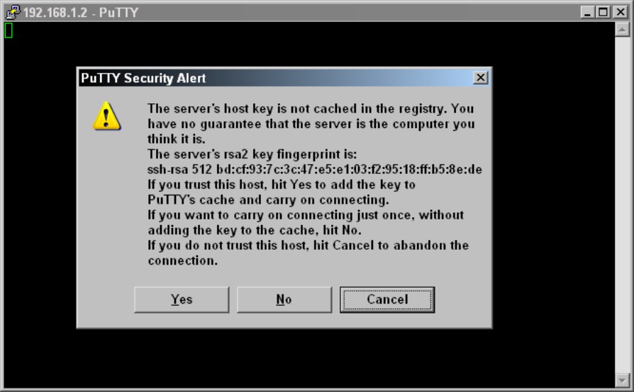
When you make your initial connection to any SSH device, you are asked to verify its public security key, as shown in Figure 5-10. This key is used as a safety device, and with PuTTY, if that key ever changes, you are prompted and you should question if it should have changed or if someone is trying to break into your Cisco device.
![]() If your key ever changes but you did not authorize it, you may want to cancel the connection and find out why the key is different. For instance, someone could have tried to capture data on your network or spoof your Cisco device’s IP address.
If your key ever changes but you did not authorize it, you may want to cancel the connection and find out why the key is different. For instance, someone could have tried to capture data on your network or spoof your Cisco device’s IP address.
Figure 5-10:
SSH initial key verification dialog box.
Graphical configuration interfaces
To make life easier for you, rather than making all your configuration changes from the command line, Cisco gives you some graphical options depending on the class of product you are using, which varies from Home to Enterprise products.
Small Business devices
To start with, many of the Small Business devices, such as the Security Appliance (SA) 520 firewall, do not have a standard IOS command line but instead offer a web interface for configuration. This web interface greatly reduces the complexity of configuration for Small Business users, who often perform much of their own configuration. Figure 5-11 shows the basic web interface of the SA 520, which places all configuration options in easy-to-navigate menus.
Home devices
Most Home users also perform their own configuration, or get a friend to do it for them. In the Home product line, streamlining configuration options in a few menus is critical for making the home experience easy and painless for users. Figure 5-12 gives you a small example of this with a Cisco WRT54G2 wireless router. By making these devices easy to configure, they often have limited functionality compared with their larger cousins. However, most Home users have no need for most of the functionality that is removed from these Home devices.
Figure 5-11:
Web interface from a Cisco Small Business device.
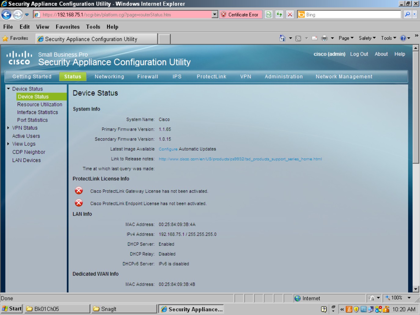
Figure 5-12:
Web interface from a Cisco ome device.

Enterprise devices
Almost all Enterprise devices have an IOS command line for configuration, which for the most part varies little from platform to platform, other than functionality that exists only in a single platform. For example, the same basic commands are used to apply an IP address to a network interface, whether you work on an Adaptive Security Appliance (ASA) firewall, a router, or a switch. To make things simpler for some administrative users who do not want to get into the weeds learning how to do things, many of these devices now have web interfaces to make the configuration tasks easier. The Cisco switches have a web interface that applies basic port setup and monitoring configuration; however, detailed configuration still requires that you get into the command line. Many Cisco routers, especially the Branch Integrated Services routers have a Java-based graphical program, Security Device Manager (SDM), as shown in Figure 5-13.
Figure 5-13: The SDM interface makes Enterprise routers less intimidating.

You might note in the figure that the top menu has three main options: Home, Configure, and Monitor:
• The Home page gives you a basic snapshot of the device status.
• The Configure page has a navigation pane down the left of the screen that allows you to configure the main components of the system, such as network interfaces, firewall policies, virtual private networks (VPNs), and routing, to name a few.
• The Monitor page allows you to see more detailed information on the status of your device that you see on the Home page.
The Cisco ASA Security Device Manager (ASDM), as shown in Figure 5-14, is similar to the SDM in appearance, down to the three main menu items on the main toolbar. The ASDM is also similar to the SDM in operation, with the configuration performed on the Configure page. ASDM is a Java-based application that is stored on the device and launched from a web interface. Almost all functionality of the security device can be configured through the web interface, so a user rarely needs to venture into the depths of the command line.
Figure 5-14: The ASDM interface on the ASA Firewall.
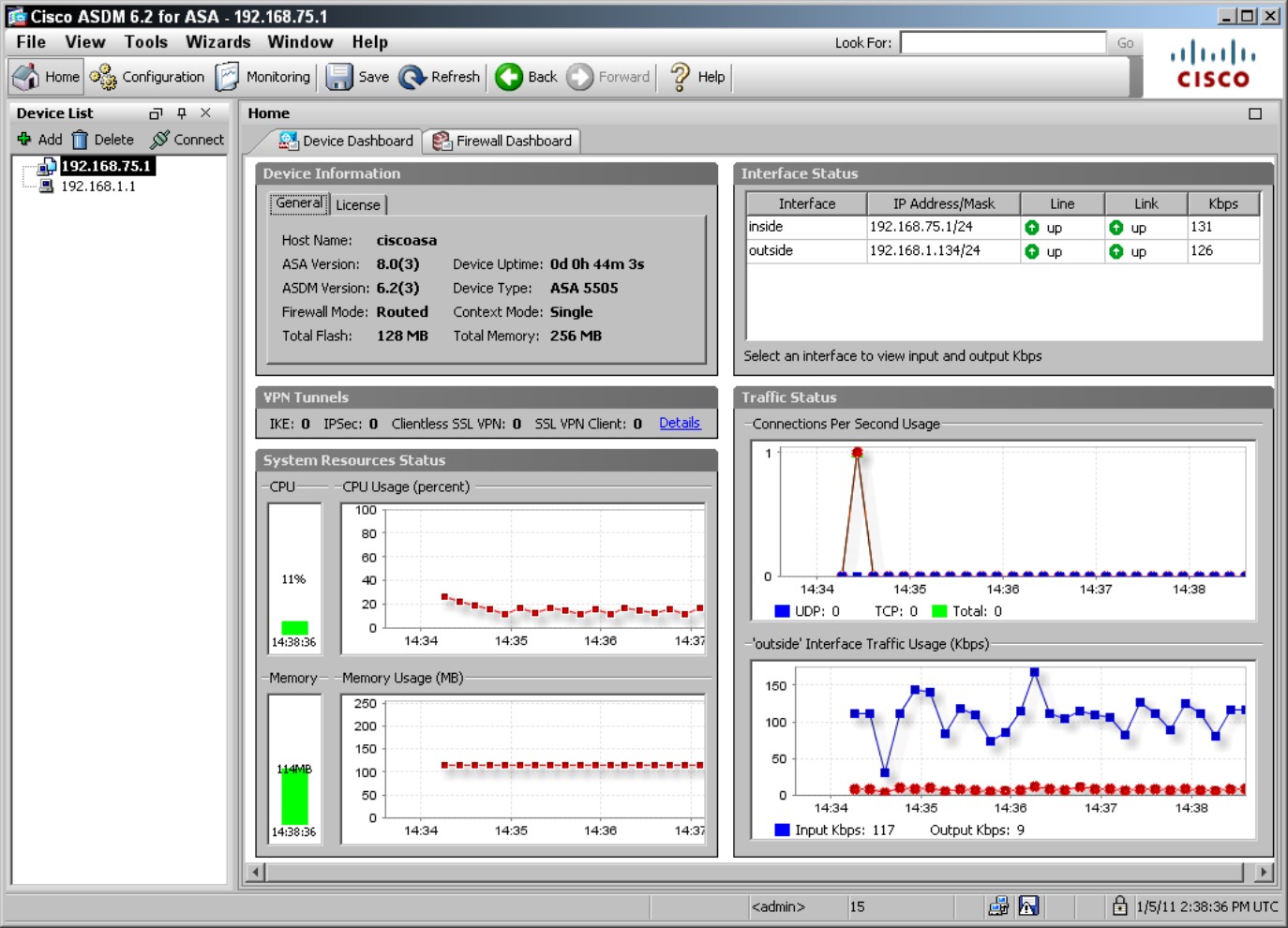
In the case of both the SDM and ASDM, all configuration is performed through the command line. When the interface loads, it reads the running-config from the device and then displays it graphically. As you make changes, the software parses new commands to change the running configuration and applies that configuration to the device effectively at the IOS command line.
Although many of the network devices from Cisco have a graphical configuration interface, they are not all equal. In some cases, they are the only option for configuration, whereas in other cases, they augment the very powerful command line.
Upgrading Firmware and Booting an IOS Image
In this section, I show you how the basic boot process works for Cisco devices as well as how to update the IOS image, or the firmware.
Upgrading the IOS image
So how do you get the IOS file to the device in the first place? Some of the graphical management tools allow you to upload the image using your web browser and HTTP, but you can also use the USB port on some devices or a removable Flash card (the latter two require that you have physical access to the device). The most common way to get the IOS to your devices is through a TFTP server. Cisco used to provide a free TFTP server that you could download to load the image via the server, but Cisco has discontinued this because there are many inexpensive or free alternatives. Cisco puts its development efforts elsewhere. The following are a couple good (and free!) choices to use as your TFTP server:
• Tftpd32: Open source TFTP server software. (http://tftpd32.jounin.net)
• The SolarWinds TFTP Server: SolarWinds’ TFTP server is available for download from its FTP site. When running their server software, SolarWinds is a bit chatty about telling you about great products for purchase, but submitting to their advertising is the price you pay for their “free” software. (www.solarwinds.com/products/freetools/free_tftp_server.aspx)
Both of these user interfaces are shown in Figure 5-15.
Figure 5-15: Most TFTP servers do not require much configur-ation.
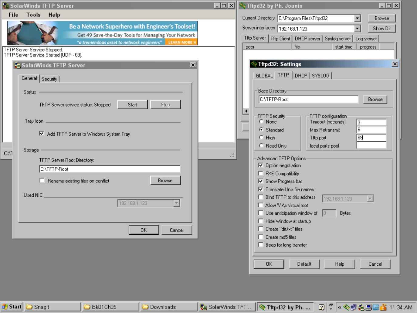
With most TFTP servers, you
1. Specify a directory to share or serve up via TFTP with the main screen showing you server activity.
You get a list of the IP addresses and what files they have uploaded or downloaded from the directory.
2. Download your IOS image files from Cisco.
You need a support agreement to be able to download the IOS image files for your device. You can find this software at the Cisco support portal (www.cisco.com/cisco/web/support/index.html), following the Download Software link on that page, and then following the navigation tool on the page to locate the IOS image for your Cisco device. After you have them, you can move to Step 3.
3. Place them in the C:TFTP-Root directory (or whatever directory you have set as your root TFTP directory).
With the files there, move over to your Cisco device to retrieve the files as you will see
Router1>enable
Password:
Router1#copy tftp: flash:
Address or name of remote host []? 192.168.1.3
Source filename []? c2600-advipservicesk9-mz.123-4.T4.bin
Destination filename [c2600-advipservicesk9-mz.123-4.T4.bin]?
Accessing tftp://192.168.1.3/c2600-advipservicesk9-mz.123-4.T4.bin...
Loading c2600-advipservicesk9-mz.123-4.T4.bin from 192.168.1.3 (via FastEtherne
t0/0): !!!!!!!!!!!!!!!!!!!!!!!!!!!!!!!!!!!!!!!!!!!!!!!!!!!!!!!!!!!!!!!!!!!!!!!!
!!!!!!!!!!!!!!!!!!!!!!!!!!!!!!!!!!!!!!!!!!!!!!!!!!!!!!!!!!!!!!!!!!!!!!!!!!!!!!!
!!!!!!!!!!!!!!!!!!!!!!!!!!!!!!!!!!!!!!!!!!!!!
[OK - 23134968 bytes]
23134968 bytes copied in 102.648 secs (225382 bytes/sec)
After you copied the image to your Cisco device, use the same process you see later in this chapter in the “Choosing a boot image” section, to select a boot image. With the new IOS file set as the boot image, you can continue the boot process with the new IOS file. Voilá! System upgraded.
![]() If you have enough storage space on your device, you can also do this process with the router running, and using the ROM Monitor mode, which is a small OS that is used to load the IOS image. This process is detailed in the “Recovering a Cisco device” later in this chapter.
If you have enough storage space on your device, you can also do this process with the router running, and using the ROM Monitor mode, which is a small OS that is used to load the IOS image. This process is detailed in the “Recovering a Cisco device” later in this chapter.
![]() After you have completed the upgrade and are sure that everything is working correctly, you can delete any old IOS images that you no longer need. This frees up space on Flash memory for future upgrades.
After you have completed the upgrade and are sure that everything is working correctly, you can delete any old IOS images that you no longer need. This frees up space on Flash memory for future upgrades.
It is often a good idea to keep your last image around for a while until you are sure there are no major issues with the new IOS. You can also use this image for troubleshooting or diagnostics. Do not forget, before you delete the image, you can copy it to your TFTP server so that you can reload it later.
Managing the boot process
To get started, here is an overview of the Cisco boot process (see Figure 5-16):
1. The Boot ROM initializes all hardware and performs a Power-On Self Test (POST) to ensure that the hardware is functional.
Any errors are reported to the console as part of the POST process.
Figure 5-16:
The Cisco boot process for Enterprise products.
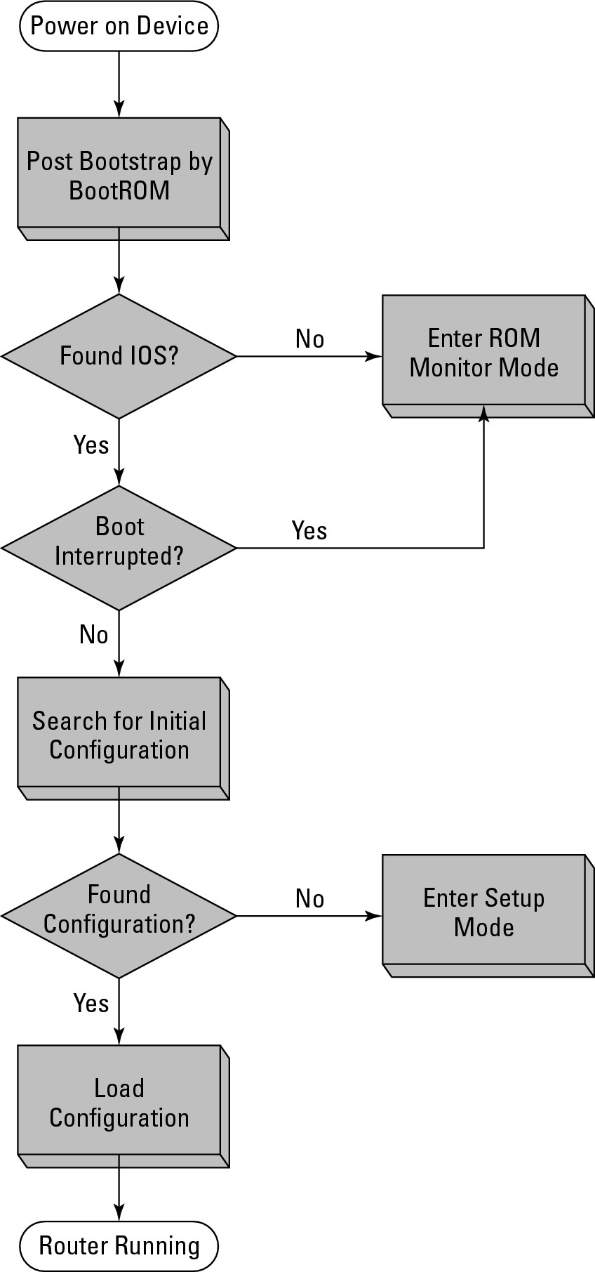
2. The Boot ROM locates and loads a valid Cisco IOS image and loads the first valid image it finds unless a boot value has been set.
The Boot ROM looks for an image first in Flash and then if a Boot-Helper image is available, attempts to load an IOS from a TFTP server (tftpdnld). If none is found, the Boot ROM loads the rxboot IOS image, or the ROM Monitor mode (ROMmon).
3. When a valid image is found, the IOS is loaded into system memory, or RAM.
4. The IOS checks the configuration register value stored in NVRAM.
This is normally set to boot the startup-config file. If the startup-config is missing or if the configuration register value dictates, the device enters Setup mode rather than loading the configuration.
Recovering a Cisco device
If you need to change boot configuration options, you can interrupt the boot process. Within 60 seconds of starting or restarting the device, you need to press the Break key or Ctrl+C, depending on your hardware. Doing so brings you to the ROM Monitor mode (ROMmon). ROMmon is a small OS that allows you to do a few basic tasks, such as copy a file to your device so that it can be used as the boot image. In the worst-case scenario, you can get into ROMmon and bring yourself back from the brink.
After you are in ROMmon, you can use a few basic commands to load an image from a TFTP server (192.168.1.3). Here is a sample of the process to load an IOS via ROMmon when you do not have an IOS loaded on the router, or you have loaded the wrong file and the system will not boot. In the following example, the system is bootable, so this is just for illustration. Pay close attention to the question the ROMmon asks because it will erase all the contents of Flash, so any other files that you do not want to lose need to be backed up.
System Bootstrap, Version 12.2(8r) [cmong 8r], RELEASE SOFTWARE (fc1)
Copyright (c) 2003 by cisco Systems, Inc.
PC = 0xfff0ac3c, Vector = 0x500, SP = 0x680127d0
PC = 0xfff0ac3c, Vector = 0x500, SP = 0x680127c0
C2600 platform with 131072 Kbytes of main memory
PC = 0xfff0ac3c, Vector = 0x500, SP = 0x80004884
monitor: command “boot” aborted due to user interrupt
rommon 1 > dev
Devices in device table:
id name
flash: flash
rommon 2 > dir flash:
File size Checksum File name
23134968 bytes (0x16102f8) 0x9978 c2600-advipservicesk9-mz.123-4.T4.bin
1885 bytes (0x75d) 0x454c sdmconfig-26xx.cfg (deleted)
16264 bytes (0x3f88) 0x1c9e sdm.shtml
3176448 bytes (0x307800) 0x1c34 sdm.tar (deleted)
1462 bytes (0x5b6) 0x8c5e home.html (deleted)
216064 bytes (0x34c00) 0xf287 home.tar (deleted)
1038 bytes (0x40e) 0xddd8 home.shtml
1652 bytes (0x674) 0x6b5a sdmconfig-26xx.cfg
113152 bytes (0x1ba00) 0xac3e home.tar
234040 bytes (0x39238) 0x965b attack-drop.sdf
1007616 bytes (0xf6000) 0x1f57 common.tar
4049920 bytes (0x3dcc00) 0xb4ce sdm.tar
rommon 3 > IP_ADDRESS=192.168.1.1
rommon 4 > IP_SUBNET_MASK=255.255.255.0
rommon 5 > DEFAULT_GATEWAY=192.168.1.254
rommon 6 > TFTP_SERVER=192.168.1.3
rommon 7 > TFTP_FILE=c2600-advipservicesk9-mz.123-4.T4.bin
rommon 8 > TFTP_RETRY_COUNT=20
rommon 9 > sync
rommon 10 > tftpdnld
IP_ADDRESS: 192.168.1.1
IP_SUBNET_MASK: 255.255.255.0
DEFAULT_GATEWAY: 192.168.1.254
TFTP_SERVER: 192.168.1.3
TFTP_FILE: c2600-advipservicesk9-mz.123-4.T4.bin
Invoke this command for disaster recovery only.
WARNING: all existing data in all partitions on flash will be lost!
Do you wish to continue? y/n: [n]: y
.....
Receiving c2600-advipservicesk9-mz.123-4.T4.bin from 192.168.1.3 !!!!!!!!!!!!!!!!!!!!!!!!!!!!!!!!!!!!!!!!!!!!!!!!!!!!!!!!!!!!!!!!!!!!!!!!!!!!!!!!!!!!!!!!!!!!!!!!!!!!!!!!!!!!!!!!!!!!!!!!!!!!!!!!!!!!!!!!!!!!!!!!!!!!!!!!!!!!!!!!!!!!!!!!!!!!!!!!!!!!!!!!!!!!!!!!!!!!!!!!!!!!!!!!!!!!!!!!!!!!!!!!!!!!!!!!!!!!!!!!!!!!!!!!!!!!!!!
File reception completed.
Copying file c2600-advipservicesk9-mz.123-4.T4.bin to flash.
Erasing flash at 0x61380000
program flash location 0x609b0000
rommon 11 > reset
![]() If you want to test an IOS image file prior to deploying but you do not have enough space on Flash to store it, you can use
If you want to test an IOS image file prior to deploying but you do not have enough space on Flash to store it, you can use tftpdnld -r to load and run it from Dynamic Random Access Memory (DRAM).
This process would then completely restore the selected image to the Cisco device. If there were other files (such as the SDM or ASDM files, or other files you send to clients) on the device, you would need to restore them. Take note the last line in the preceding code, you restart the device with the reset command.
Choosing a boot image
If you have more than one IOS image on your device, you would normally choose which one you want to use by setting the boot configuration options in the startup-config file, rather than relying on the first valid IOS that is found. You will have to wait until after you have a running IOS as this is set in the configuration that is stored in NVRAM. To change the boot image that you are using, enter Configuration mode, as in the following code:
Router1>enable
Password:
Router1#configure terminal
Enter configuration commands, one per line. End with CNTL/Z.
Router1(config)#boot system flash c2600-advipservicesk9-mz.123-4.T4.bin
Router1(config)#exit
Router1#
*Mar 1 10:49:38.095: %SYS-5-CONFIG_I: Configured from console by console
Router1#copy running-config startup-config
Router1#reload
Proceed with reload? [confirm]
*Mar 1 10:51:27.247: %SYS-5-RELOAD: Reload requested by console. Reload Reason: Reload command.
The boot image specified is loaded as long as it exists on Flash. If the file is deleted from Flash, the boot process continues with the next boot parameter in the configuration file or the first valid IOS file that is located on Flash.
Recovering a device with a lost password
In this section, I show you another common function that you may need to use the ROMmon interface for. You may already have an old Cisco router or switch on your storage shelf that you cannot use because you do not have the enable password for it. Well, with your trusty Cisco rollover cable, you can use ROMmon to recover the password. Recovering the password may differ slightly based on your device, but most devices use the process described here to tweak the configuration register. If you have a running device of the same type (same model, such as a 2900 Series Router), you can run show version to find out what the default configuration register value is set to. In most cases, the register is set to 0x2102. Let me explain what that means.
Several settings can be stored in the configuration register, and they are totaled into a single value. So all the 16-bit values are added together to give you the value that is stored in the register. In the following bullets, I give a brief summary of the main values to worry about.
The lowest four bits control the boot settings:
• Boot field equals 0000: Do not load a system image; enter into ROMmon mode. This allows you to manually load an image to boot.
• Boot field equals 0001: Load the first valid image in Flash.
• Boot field between 0010 and 1111: Load the image specified in the boot command in the configuration file stored in NVRAM; if this is not possible, stay in ROMmon.
In addition to the boot values, other values that are of interest include
• Bit 6 (0x0040): Clear the NVRAM contents, this value will be the value to use to clear the existing enable password. Clear the entire contents of NVRAM.
• Bit 8 (0x0100): Disable the break command.
• Bit 13 (0x2000): Boot the IOS image on Flash if network boot fails or is not used.
You can use the show version command to find out what your configuration register is set to. So if the default register value is 0x2102 (Boot Flash IOS if no network boot, disable Break after system is running, and load items listed in boot configuration), change it to 0x2142 (Boot Flash IOS if no network boot, clear NVRAM, disable Break after system is running, and load items listed in boot configuration). To perform password recovery, follow this process, reload your router, and break into ROMmon, as I describe earlier:
System Bootstrap, Version 12.2(8r) [cmong 8r], RELEASE SOFTWARE (fc1)
Copyright (c) 2003 by cisco Systems, Inc.
PC = 0xfff0ac3c, Vector = 0x500, SP = 0x680127d0
PC = 0xfff0ac3c, Vector = 0x500, SP = 0x680127c0
C2600 platform with 131072 Kbytes of main memory
PC = 0xfff0ac3c, Vector = 0x500, SP = 0x80004884
monitor: command “boot” aborted due to user interrupt
rommon 1 > confreg 0x2142
rommon 2 > reset
After the reset, you are asked to go through the setup process again. Answer “no” to these requests and then follow this process.
Router>enable
Router#copy startup-config running-config
Router1#show running-config
Router1#configure terminal
Enter configuration commands, one per line. End with CNTL/Z.
Router1(config)#enable secret <password>
Router1(config)#config-register 0x2102
Router1(config)#exit
Router1#
*Mar 1 10:49:38.095: %SYS-5-CONFIG_I: Configured from console by console
Router1#copy running-config startup-config
Building configuration...
[OK]
Router1#reload
Proceed with reload? [confirm]
*Mar 1 10:51:27.247: %SYS-5-RELOAD: Reload requested by console. Reload Reason: Reload command.
Because you have changed the configuration register from the configuration screen, you do not need to enter ROMmon to change back. It is not uncommon for this step to be forgotten, so each time you boot the device, you continually enter Setup mode. Do not worry; if you still have a valid startup-config file in NVRAM, follow the immediately preceding code to the end. If you do not have the startup-config file, run setup to restore your settings and change the config-register value.