
CHAPTER 16
Using Annotations and Symbols
IN THIS CHAPTER
Inserting and creating blocks
Accessing symbols
Appling center marks and centerlines
Using annotations tutorial
Annotations and symbols are a major component of communicating a design through a drawing. SolidWorks has several tools available to help you manage these entities to make engineering drawings look good and communicate effectively.
Using Notes
![]() Notes are the workhorse of SolidWorks annotations. You can use notes in many different configurations and mix them with links to custom properties, hyperlinks, and text wrapping boxes. You can also use them with styles, leaders, symbols, and balloons; and you can even embed balloons into notes.
Notes are the workhorse of SolidWorks annotations. You can use notes in many different configurations and mix them with links to custom properties, hyperlinks, and text wrapping boxes. You can also use them with styles, leaders, symbols, and balloons; and you can even embed balloons into notes.
Setting up a workflow for placing notes
Sometimes users have difficulty working through some of the interfaces in SolidWorks. This is not necessarily the fault of the software, but is often because users may not fully understand how the workflow of a particular feature is designed to function. The Model View interface from the last chapter is one that can be confusing until you have been through it a few times and gain a more intuitive feel for how it works.
Understanding the workflow is paramount to being able to use the software efficiently. I sometimes find myself using the annotations clumsily, and sometimes wind up with blank notes, double notes, or extra lines at the ends of notes. After using the tool a few times, I get back in the groove.
For these reasons, I have added an outline of the workflow here to help you create annotations more efficiently.
Follow these steps to create a note:
- Click the Note toolbar button on the Annotations toolbar.
- Click in the graphics window where you want to create the note or click an entity that you want the note leader to point to, and then click where you want the note.
- Type the note. Press Enter at the end of a line, or, if you intend to force the note to wrap later, just allow the line of text to be as long as it wants to be. While you create the note, the text box expands to the right until you press Enter, and it expands down every time a line is added.
At the end of the last line of the note, do not press Enter again (this creates extra lines), but you may press Esc. Esc gets you out of the note and ready to place a new note. When you press Esc twice, you get out of the note you were typing, and then get out of the Note command altogether.
- Another way to finish the note is to click the mouse outside of the text box. After that, if you are done, press Esc. If you want to continue with another note, click again to place it, and start typing. If you want to place the same note as the first one again, the text is already there, so click a second time.
Making use of fonts
SolidWorks can make use of any TrueType fonts that Windows will accept. This includes symbol, non-English, and Wingding fonts. SolidWorks does not use true monofonts like AutoCAD because they do not have width information and thus do not print like fonts with widths. Some AutoCAD monofont look-alike fonts are installed with SolidWorks that do have a very narrow width, and are shaped like some of the monofonts.
In the Customize dialog box (Tools ![]() Customize), the Fonts toolbar displays as the Formatting toolbar. The Formatting toolbar also appears in the graphics area immediately over your text every time you either insert a new note or edit an existing note, unless the toolbar is already docked somewhere. The Formatting toolbar is shown in Figure 16.1.
Customize), the Fonts toolbar displays as the Formatting toolbar. The Formatting toolbar also appears in the graphics area immediately over your text every time you either insert a new note or edit an existing note, unless the toolbar is already docked somewhere. The Formatting toolbar is shown in Figure 16.1.
FIGURE 16.1 The Formatting toolbar
![]()
Using text boxes and wrapping
Text boxes enable you to limit the size, particularly the width, that a note can occupy. This enables notes to wrap in tight spaces on title or revision blocks, as well as other places.
You can size text boxes immediately after placement, even while they are blank; the text then wraps to fit the box width as you type it. The text box expands downward automatically. Blank text boxes can be left on the drawing to provide a placeholder for future text. The blank text box has a rectangular border that contains an X, both of which are removed when you add text. If spaces are added to a text box, the text box becomes invisible, although you can select it if you know where it is. When you move the cursor over the text box, the cursor displays the note symbol.
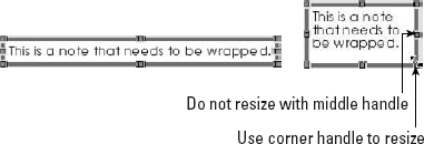
While typing a note, it is not possible to make the note box smaller using the middle handle on the right end of the box; you can only stretch it larger. Using any corner handle, as shown in Figure 16.2, you can make the box taller, wider, or narrower. The note box will not resize smaller if the text string it contains does not contain spaces.
FIGURE 16.2 Resizing a text box using the lower-right corner handle
If a custom property value is used to populate a note and you select the Annotation Link Variables option in the Views dialog box, when you activate the text box to resize it, the text value will go away and the link variable will be displayed. This makes it difficult to dynamically resize the box to fit the note, so it might be best to deselect the Annotation Link Variable option before placing and sizing notes.
Using Fit Text in notes
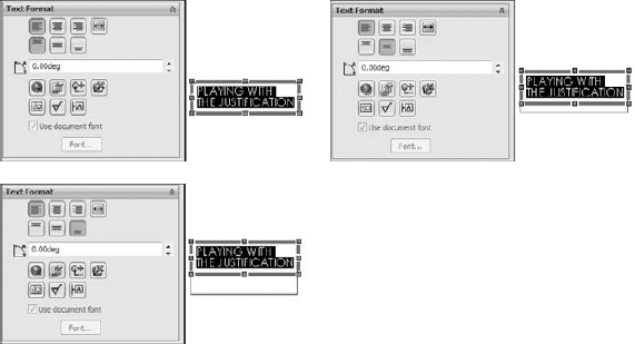
![]() The Text Format panel of the Note PropertyManager, shown in Figure 16.3, contains the justification buttons for note text, but also has a Fit Text option. When the Fit Text button is depressed, changing the width of the text box changes the width of the individual characters.
The Text Format panel of the Note PropertyManager, shown in Figure 16.3, contains the justification buttons for note text, but also has a Fit Text option. When the Fit Text button is depressed, changing the width of the text box changes the width of the individual characters.
FIGURE 16.3 Stretching the characters in note text by using Fit Text

Figure 16.3 shows the Note Property Manager when you are editing text. When you are creating the note, the vertical justification buttons (to the left of the Fit Text tool tip) are not displayed. These are called (from left to right) Top Align, Middle Align, and Bottom Align. They work differently from most vertical justification tools that you find in Microsoft Word or PowerPoint. In Microsoft applications, this feature justifies the text within the text box, but SolidWorks vertical justification justifies the text box on the placement point. So if you click a spot on the drawing sheet and use Bottom Align, the bottom of the text box will go to that point. It winds up working almost backwards from what you might be used to if you use Microsoft applications. Figure 16.4 shows what this justification does. Selecting the Bottom Align option actually makes the text move up, even though the graphic on the icon definitely shows it going down.
FIGURE 16.4 Using the vertical justification options in a note
Patterning notes
![]() Starting in SolidWorks 2011, you are now able to pattern notes in linear and circular patterns. Both commands are in the Annotation tool set, but are not on the toolbar by default. To put them on the toolbar, go to Tools
Starting in SolidWorks 2011, you are now able to pattern notes in linear and circular patterns. Both commands are in the Annotation tool set, but are not on the toolbar by default. To put them on the toolbar, go to Tools ![]() Customize
Customize ![]() Commands
Commands ![]() Annotations, and drag them from the dialog box to the toolbar area. Figure 16.5 shows the Linear Note Pattern PropertyManager. It looks very similar to the sketch pattern PropertyManager.
Annotations, and drag them from the dialog box to the toolbar area. Figure 16.5 shows the Linear Note Pattern PropertyManager. It looks very similar to the sketch pattern PropertyManager.
Once the note is patterned, you can change individual pattern instances. I have to mention, though, that changing a patterned note does not work the same as changing a regular note. In a regular note, you double-click to activate it and type to replace the note contents. With a patterned note, you have to activate it, click again to deselect the text, press Delete or Back to remove the text, and then type new text.
Circular patterns work similarly to linear patterns, and also work like circular sketch patterns, with the same editing limitations.

Placing notes and leaders
When you start to place a note, a preview shows the text box with or without a leader depending on the position of the cursor. If the cursor is over a blank section of the drawing, the note is placed without any leader. If the cursor is over a face, edge, or vertex, then a leader is added using the arrow found in the Attachment dialog box at Tools ![]() Options
Options ![]() Document Properties
Document Properties ![]() Arrows
Arrows ![]() Attachments. By default, a leader attached to a face uses a dot as an arrow, and a leader attached to an edge, sketch entity, or nothing at all uses a regular arrow. You can change these defaults at the options location mentioned previously, and you can change individual note leaders in the PropertyManager that becomes available when you select a note. These settings can also become part of a custom drafting standard.
Attachments. By default, a leader attached to a face uses a dot as an arrow, and a leader attached to an edge, sketch entity, or nothing at all uses a regular arrow. You can change these defaults at the options location mentioned previously, and you can change individual note leaders in the PropertyManager that becomes available when you select a note. These settings can also become part of a custom drafting standard.
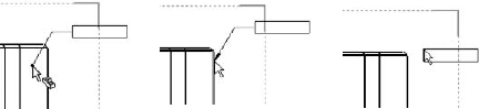
Figure 16.6 shows the preview that is displayed by the cursor when you place a note over a face, an edge, and blank space on the drawing.
FIGURE 16.6 Placing a note with a leader
You can also change settings for bent leaders by choosing Tools ![]() Options
Options ![]() Document Properties. It is recommended that you use the same bent leader lengths for all annotations, and save them in the templates that you use.
Document Properties. It is recommended that you use the same bent leader lengths for all annotations, and save them in the templates that you use.
Single-clicking inside an active text box places the cursor between letters, as expected. Double-clicking inside an active text box selects the entire word that you click, again as expected. Ctrl+A selects all the text inside a text box. If you double-click an existing note to activate it, the entire contents are highlighted immediately. You also cannot drag-and-drop selected text to move it within a text box. However, you can Ctrl+C, Ctrl+X, and Ctrl+V the text.
To format the entire note, do not activate the text box; instead, only select the border of the note, and apply the setting to the entire note rather than to selected text within the note.
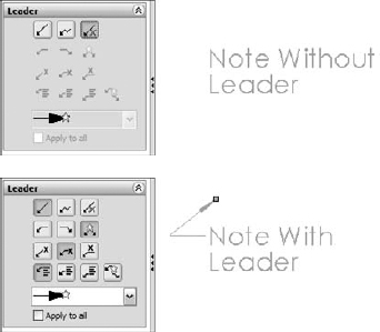
Adding a leader to a note
To add a leader to a note that was created without a leader, click the note and select the leader options in the Leader panel of the PropertyManager, as shown in Figure 16.7. After you add the leader, you can reposition the handle at the end of the leader to attach it to an entity on the drawing.
FIGURE 16.7 Adding a leader to a note
Using multiple leaders
You can also attach multiple leaders to notes. To create a new note with multiple leaders, pre-select the entities that the leaders are to be attached to, and then click the Note toolbar button.
To add a leader to an existing note, first click the note, and then Ctrl+drag the handle or small dot on the end of a leader to the second location. A note with multiple leaders is shown in Figure 16.8. To remove one of multiple leaders from a note, click the handle at the end of the arrow and press Delete.
FIGURE 16.8 A note with multiple leaders

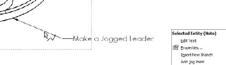
Using jogged leaders
Jogged leaders have come a long way since their introduction many releases ago. You can switch a regular leader to a jogged leader by selecting an option in the PropertyManager. In Figure 16.7, the middle icon in the top row is the Jogged Leader icon. The icon to the left simply turns on the default leader, and the icon to the right turns off leaders altogether.
Once you activate the jogged leader option, you can add a jog from the leader right mouse button (RMB) menu. Notice in Figure 16.9 that two options give you control over the jogged leader — Insert New Branch and Add Jog Point.
Adding a jog point
Selecting the Add Jog Point command adds a new handle to the leader that you can move around. You can add multiple jog points to the leader.
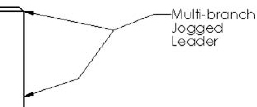
Inserting a new branch
The Insert New Branch command enables you to create a new jogged leader that ends in another arrow from the selected point. This arrangement with multiple branches in a jogged leader is shown in Figure 16.10.
FIGURE 16.10 The results of adding a new branch to a jogged leader
Adding styles
For notes, a style can apply a font, an underline, bold formatting, or any other setting from the Formatting (Fonts) toolbar to a note.
To create a note that uses the style setting from another existing note, pre-select the existing note with the style to be copied before starting the Note command; SolidWorks applies the style to the new note.
Caution
Sometimes adding a style to a note can make other changes that you may not expect, such as turning off the leaders if a note has multiple leaders. In particular, if the style is made from a note with a jogged leader, then it turns off leaders for regular multiple leaders. Styles that are created from regular leader notes do not turn off jogged leaders.
Making a change to the leader of a note after you apply the style removes the style from the note, although the formatting remains. This does not apply to adding multiple leaders, only to changing the type of leader.
Applying a style may also remove the ability of the text to wrap, as well as any changes to the text box shape. You cannot move the corner of a text box of a note to which you have applied a style.
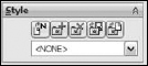
Styles exist only in the document in which they were created, but they can be shared to other documents by saving the style out as a separate file. Note styles use the extension *.sldnotestl. Once you save the style, you can load it into other documents. The Style panel of the Note PropertyManager interface is shown in Figure 16.11.
FIGURE 16.11 The Style panel of the Note PropertyManager interface
Annotation types that can use styles are
- Note
- Dimension
- Weld Symbol
- Surface Finish
- Datum Feature
- Datum Target
- Balloon
- Auto Balloon
- Stacked Balloon
- Center Mark
Note
Styles before the 2009 release were called Favorites, and some functions still retain the old name. The file type for note favorites was *.sldnotefvt. If you run across any of these legacy file types, you will at least know what they are. When loading styles, the Open dialog box will recognize and use both the new file type and the legacy file type.
The Style panel contains the following buttons:
 Apply Defaults/No Styles. Removes style settings from the current interface, setting all values back to the defaults.
 Add or Update Styles. Either adds a new style to the database or changes the name or other settings for an existing style.
 Delete Style. Removes a style from the database.
 Save Style. Saves a style to an external file (*.sldhwfvt), which can be loaded by other users and added to their databases.
 Load Style. Loads a saved style file.
Styles can be loaded into document templates so that for every document created from the template, those Styles will be available.
Linking notes to custom properties
You can link notes to custom properties. The custom properties can be from the drawing or from the model that is referenced by the drawing. I mention this kind of link briefly in Chapter 20, but discuss it more thoroughly here.
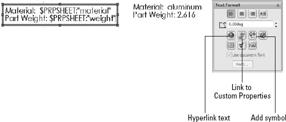
Figure 16.12 shows a note on a drawing with custom property links pulling data from the model shown on the drawing. To add these links, driven by the syntax $PRPSHEET:“material”, click the icon indicated in the image to the right in Figure 16.12.
FIGURE 16.12 Linking notes to custom properties
In this case, text has been combined with custom properties, but custom properties can also appear alone. To access the Custom Properties interface, choose Tools ![]() Properties.
Properties.
When you activate the note, you may want to see the syntax, or you may want to see the actual text value of the custom property. You can find the setting that controls which one is displayed by choosing View ![]() Annotation Link Variable.
Annotation Link Variable.
Hyperlinking text
Hyperlinking text is sometimes useful on drawings to provide a link to reference documentation, specification, test results, and so on. The first button in the third row of the Text Format panel of the Note PropertyManager enables you to add a hyperlink to text in the note. Figure 16.12 shows this panel. Either copy the URL to the hyperlink dialog box that appears or browse to it from the dialog box.
Note that there is a bug in SW (which has been around for years!), including SW2011 SP0 where you cannot un-hyperlink a box. Once you type “http://” into a note, it automatically turns the entire note into a hyperlink. According to the Knowledge Base you are supposed to right-click on the note, and then select the hyperlink button in the FeatureManager, where you can then delete the link and click OK to remove the link. Unfortunately, this just produces an error. If you want to put a Web address into your drawing note without it turning into a hyperlink, you have to trick Solidworks into not recognizing it as a Web link. I suggest putting a space between the : and the // of the link, which will not be obvious on a printed drawing.
Adding notes and symbols
Notes and symbols are regularly combined in SolidWorks. Symbols are discussed more fully later in this chapter, but are mentioned here because of the frequency with which they are used with notes. In reference to Figure 16.12, the image to the right shows the Text Format panel, which contains a button to the interface where you can add symbols.
Using Blocks in Drawings
Blocks in SolidWorks can contain sketch elements and notes. When used in drawings, blocks have several common uses, including the following:
- You can use standard note blocks for tolerances, disclaimers, or default requirements.
- You can put together a mechanism in 2D where each block represents a part.
- You can use flow direction for fluid systems.
- You can use drawing stamps such as “Not For Release,” “Preliminary,” “Obsolete,” and so on.
- You can use symbols for schematics that can be snapped together.
- You can save drawing formats as blocks to make them easier to place as a single entity.
Like styles, blocks reside in the document in which they are created, but you can save them out to a *.sldblk file, load them into other documents, and save them as a part of a document template.
Inserting blocks
![]() You can apply blocks in several ways, including by dragging from Windows Explorer and by using the Block menus (Insert
You can apply blocks in several ways, including by dragging from Windows Explorer and by using the Block menus (Insert ![]() Annotations
Annotations ![]() Block). However, the most efficient way is to access them from the Design Library. Library folders can be established specifically for blocks. Check the setting by choosing Tools
Block). However, the most efficient way is to access them from the Design Library. Library folders can be established specifically for blocks. Check the setting by choosing Tools ![]() Options
Options ![]() File Locations
File Locations ![]() Blocks, and redirect this setting to a library area outside of the SolidWorks installation directory. Figure 16.13 shows the Design Library with a folder containing blocks that are selected. The blocks do not show previews in the window, but the tool tip displays large previews. You can drag blocks from the Design Library onto the drawing sheet.
Blocks, and redirect this setting to a library area outside of the SolidWorks installation directory. Figure 16.13 shows the Design Library with a folder containing blocks that are selected. The blocks do not show previews in the window, but the tool tip displays large previews. You can drag blocks from the Design Library onto the drawing sheet.
Each block has an insertion point, which snaps to any sketch entity point, even if it is in another block. This makes schematics easy to snap together. If the default insertion point is not the point that you need to snap to the other geometry, then you can place the block anywhere on the drawing and drag the point that needs to snap.
Once blocks are snapped together, to detach them from one another, you can click the point at which they touch; a Coincident sketch relation displays in the PropertyManager. Deleting the sketch relation enables you to drag the block away from the other geometry.
FIGURE 16.13 Blocks in the Design Library

When blocks are inserted, you can control several options in the PropertyManager. This function may be somewhat hidden because it does not appear automatically when you place the block. After you place the block, SolidWorks wants you to place another copy of the block. If you press Esc to cancel out of placing additional blocks, the first placed block is not selected, so the PropertyManager does not display. Figure 16.14 shows the Block PropertyManager.
FIGURE 16.14 The Block PropertyManager
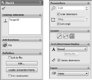
Following is a list of sketch relations linked to the block:
- Existing Relations. This panel lists the sketch relations that are linked to the block. These may cause the block to not move properly when you drag it. This feature is most helpful when the block is being used as a representation of a part in a simulated 2D mechanism.
- Add Relations. This panel enables you to quickly select sketch relations to apply when placing blocks.
- Definition. Blocks can be linked to an external file, which enables all linked instances of a block to be updated at once, even if they are being used in other drawing documents. The path box for the Link to File option only displays if you select the check box.
- The Edit button refers to editing the block. A toolbar button also exists for editing blocks. Clicking the Leader & Insertion Points button enables you to edit both of the controls. You can select the For Construction option to change the entire block to construction entities.
- Parameters. The top field with the two circles to the left controls the scale of the block. This number affects the entire block, including the text. You also have the option to scale dimensions, so that the dimension text size (not the dimension value) increases with the overall block scale.
- The Lock Angle option refers to the rotation of the block. If the Lock Angle option is not selected, then you can rotate the block if one point on it is coincident to a stationary object, such as a vertex in a drawing view.
- Leader. You will recognize these options from the Notes leaders. The leader is attached to the block where the angled black handle was placed when you created the block. You can edit the leader connection and insertion points by clicking the Leader & Insertion Points button on the Definition panel.
- Text/Dimension Display. The Display Dimensions option controls whether or not any notes and dimensions in the block are displayed or hidden.
- Layer. You can assign most entities on drawings to layers, which in turn have controls for items, such as line type, color, and visibility.
Creating blocks
![]() You can create blocks by selecting the sketch and annotation elements and clicking the Make Block toolbar button in the Blocks toolbar, or by accessing the command by choosing Tools
You can create blocks by selecting the sketch and annotation elements and clicking the Make Block toolbar button in the Blocks toolbar, or by accessing the command by choosing Tools ![]() Block
Block ![]() Make from the menus.
Make from the menus.
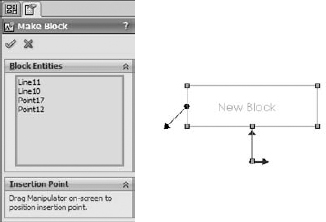
By default, when you create a block, the Insertion Point panel of the PropertyManager does not expand. If you expand this panel, the blue Origin symbol represents the insertion point that is attached to the cursor during block insertion, as shown in Figure 16.15. The angled line hanging off the left side of the block is the leader attachment point for the block. You can also drag this line around the block and snap it to sketch geometry. By default, this block does not use a leader, but if one is required, then you can select it when you place the block.
Cross-Reference
Sketch blocks are covered in some detail in Chapter 3. This chapter is limited to a discussion of blocks that may be found on drawings rather than those used in model sketches or layouts.
Editing blocks
![]() Although you do not have many options when creating blocks, many more options become available when you edit them. You can access editing options for a block from four locations:
Although you do not have many options when creating blocks, many more options become available when you edit them. You can access editing options for a block from four locations:
- The Edit Block toolbar button on the Blocks toolbar
- The Edit button in the Block PropertyManager
- Choosing Tools
 Block Edit from the menus
 - From the RMB menu of the block in the Blocks folder in the drawing FeatureManager
The standard edit function gives you access to the sketch and note elements that make up the block.
 Add/Remove Entities. While you are editing the block, the Add/Remove Entities button on the Blocks toolbar becomes available. This enables you to add or remove sketch or note entities from the block definition.
 Rebuild. Rebuild Blocks reapplies sketch relations within the block, without exiting Edit Block mode.
 Explode. Explode is available when you are not editing the block, but when it is selected. Explode returns the contents of that particular instance of the block to the drawing, removing them from the block. This removes any leaders that are attached to the block, as well as sketch relations. This is not technically an edit option, but it certainly does change things.
Using Symbols
SolidWorks symbols are different from symbols that are a part of a font family. SolidWorks symbols fall into several categories, including weld, surface finish, hole, modifying symbols, GD&T (geometric dimensioning and tolerancing), and several flag symbols. You can also construct custom symbols.
Using symbols in notes and dimensions
You can use symbols in notes and dimensions. They also are an intrinsic part of weld symbols and surface finish symbols. Hole Callouts use symbols extensively, as do GD&T frames.
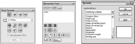
Figure 16.16 shows the Text Format panel from the Note PropertyManager and the Dimension Text panel from the Dimension PropertyManager. Both of these interfaces give you access to the symbol library.
FIGURE 16.16 Accessing symbols and the symbol library
Creating custom symbols
You can create custom symbols in SolidWorks, but creating them may not be as simple as you expect. In the langenglish subfolder of the SolidWorks installation directory is a file called Gtol.sym. This file stores the representations of all the SolidWorks symbols. It is also where you can create symbols of your own. You can edit the file in Notepad.
Be warned, however. Unless you enjoy writing scripts for the command line, or you are a fan of DOS 5.0, you may not want to create custom symbol projects. The format for creating symbols is simple enough, but it is what you might call somewhat arcane. It is effective at creating line-art symbols that can be used with text and can even be used to contain text. If you are a little inventive with this, you can create interesting shapes that integrate with your notes and dimensions.
Keep in mind that this topic does not appear in the Help files, but all the instructions you need are inside the file itself. You may have to experiment a little to discover what the rules are in terms of making shapes outside of the limits of the 1X1 matrix. It is probably easier to create the geometry using Blocks functionality, but blocks cannot be inserted into text notes as easily as symbols.
Also note, if you modify the gtol.sym file, anyone who uses the drawings you create must also have the same custom gtol.sym file. So if you actually do this and work in a group environment, make sure everyone uses the same file and it is available to others.
Using Center Marks and Centerlines
![]() You can apply center marks either manually or automatically to edges that project as circular in the drawing view. To find the settings that control automatic insertion, choose Tools
You can apply center marks either manually or automatically to edges that project as circular in the drawing view. To find the settings that control automatic insertion, choose Tools ![]() Options
Options ![]() Document Properties
Document Properties ![]() Drafting Standard
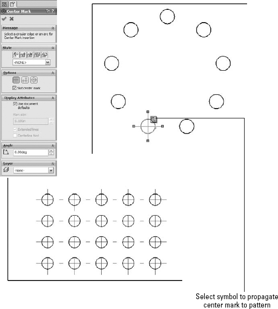
Drafting Standard ![]() Centerlines/Center Marks. The size of the mark at the center and the use of lines extending to the actual circular edge are also controlled on this tab, in the Center Marks section. Figure 16.17 shows some of the options available for center marks.
Centerlines/Center Marks. The size of the mark at the center and the use of lines extending to the actual circular edge are also controlled on this tab, in the Center Marks section. Figure 16.17 shows some of the options available for center marks.
FIGURE 16.17 Options available for center marks
Center marks propagate well to patterns, and you can dimension to them individually. You can rotate center marks in views where they need to be referenced from an edge that is not horizontal. You can also place center marks into layers.
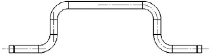
![]() You can apply centerlines to any geometry that has a temporary axis that is perpendicular to the view. Centerlines can also be placed automatically when you place the part into the drawing. You can create centerlines by selecting a face or a pair of parallel lines or concentric arcs. Centerlines may be displayed improperly on parts that are created by mirroring, as shown in Figure 16.18. This bug was originally printed here in the 2007 version and is still active for 2011 sp0.0.
You can apply centerlines to any geometry that has a temporary axis that is perpendicular to the view. Centerlines can also be placed automatically when you place the part into the drawing. You can create centerlines by selecting a face or a pair of parallel lines or concentric arcs. Centerlines may be displayed improperly on parts that are created by mirroring, as shown in Figure 16.18. This bug was originally printed here in the 2007 version and is still active for 2011 sp0.0.
FIGURE 16.18 Centerlines can display improperly on a mirrored part.
Tutorial: Using Annotations
This tutorial shows you how to use some of the tools that were discussed in this chapter. It does not cover every feature, so you should explore a little on your own and not necessarily follow the instructions exactly. Start here:
- From the DVD, open the file named Chapter 16 – Tutorial.slddrw. This is a drawing file with views of the part from Chapter 21, but it does not contain dimensions or annotations.
- Click the Center Mark tool on the Annotations toolbar. (If the button is not there, then choose Tools Customize Commands to place it on the toolbar, along with the Centerline tool.) Click one of the holes in the pattern of three, and click the Propagate symbol to propagate the center marks to all three holes in the pattern. The view should look like Figure 16.19 when you are done.
- Activate the Centerline tool to add two centerlines to the right view, in the lower-left area. Change the view display style to Hidden Lines Visible. Select the cylindrical faces for each feature to place the centerlines. Click the vertical centerline and drag the ends past the edges of the part.
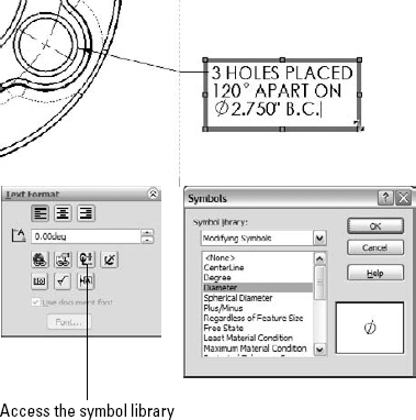
- Select the edge that is indicated in Figure 16.20, and initiate a note from the Annotations toolbar. Type the text shown, all in one line. You can place the degree and diameter symbols from the symbol library, which you can access using the indicated button in the PropertyManager. Both symbols are in the Modifying Symbols library, also shown in Figure 16.20. Drag the lower-right corner of the text box to make the text wrap as shown.
FIGURE 16.19 Center marks and centerlines on a part
FIGURE 16.20 Placing symbols in an annotation
- Draw an arrow with a text note inside it, as shown in Figure 16.21. Make the sketch and text into a block by window-selecting all of it and clicking Make Block from the Blocks toolbar, or by choosing Tools Block Make. Make sure that the end of the arrow is its insertion point. You have to expand the Insertion Point panel in the PropertyManager to access this option. When the block is set up, accept it by clicking the green check mark icon. When the block is created, delete it from the drawing.

- Place the block using the Insert Block function, so that the block is to the right of the right view. Once you place it, press Esc to cancel the placement of more blocks. Then select the block to activate the PropertyManager. Deselect the Lock Angle option, and set the angle to 270 degrees.

Summary
Annotations and symbols in SolidWorks have many options for connection, creation, and display. Recent releases have brought major improvements to text box–driven annotations. Custom properties and hyperlinks enable the user to populate drawing annotations with content and links to content. Sharing styles in templates is a great idea for readily available note styles.
Blocks have several flexible uses and can be updated from external files across many documents. Their use for simulating mechanisms, piecing together schematics, and annotating drawings, in addition to the Belts functionality discussed in Chapter 3, make blocks one of the most flexible functions available.