Although the primary purpose of an IOS router is to be a router, there are a number of built-in security features that can be leveraged such that the router takes its proper place in the Cisco Self-Defending Network. In this section, we look at typical deployment scenarios for an IOS router and examine some of the features of Cisco Integrated Services Routers (ISRs) at a high level.
Before we get into the features of Cisco’s product portfolio, we should probably cover the question of where a router is deployed as part of the implementation of a comprehensive security policy. We discussed the “blurring of the perimeter” in Chapter 2, “Building a Secure Network Using Security Controls,” but it is typically at the perimeter, or edge, of a network where we deploy routers. They are often the first bastion of defense against attack because many enterprises, both large and small, use routers as their first connection to an Internet Service Provider’s IP cloud. The router might be a customer-managed solution, in which case the customer has at least partial control of the configuration and management of the router, or the equipment could be wholly owned, configured, and managed by the ISP. Of course, the size of the network, the customer, the assets they are trying to protect, and so on, will determine both the type and depth of defense implemented. A small office/home office (SOHO) user or a teleworker probably doesn’t need multiple layers of defenses and different zones of security that a large e-commerce site requires. Common sense dictates that all of these considerations will bear on both the scope of the solution as well as the capabilities of the router that will be required.
Refer to Figure 3.1 for three common examples of where a router might be deployed. Keep in mind that the firewall in Figure 3.1 is assumed to be a stateful firewall. The reason it is deployed instead of another router is that the firewall will be able to keep track of the state of connections that are built across it (both ingress and egress) and thereby afford an extra level of protection to the network. The firewall could very well be an IOS router firewall. IOS firewalls and types of firewalls in general are examined in Chapter 5, “Using Cisco IOS Firewalls to Implement a Network Security Policy.”

The following is a detailed explanation to the three deployment scenarios in Figure 3.1:
![]() Scenario 1—Single Perimeter. The router establishes the trusted network boundary at the Internet and protects a single LAN. This is a small business (but with growth aspirations!), and they need a solution that will grow with them.
Scenario 1—Single Perimeter. The router establishes the trusted network boundary at the Internet and protects a single LAN. This is a small business (but with growth aspirations!), and they need a solution that will grow with them.
![]() Scenario 2—Two Perimeters. Business is improving and the company has more need for protection of its assets, including intellectual property. The security policy grows with the business and dictates that a firewall is purchased to establish a second perimeter behind the router, thus providing an extra level of protection for the single LAN.
Scenario 2—Two Perimeters. Business is improving and the company has more need for protection of its assets, including intellectual property. The security policy grows with the business and dictates that a firewall is purchased to establish a second perimeter behind the router, thus providing an extra level of protection for the single LAN.
![]() Scenario 3—Screened Subnet. The company’s business needs dictate that an e-commerce site be implemented. Recalling that business needs are a big driver for security policies, the company uses industry best practices to change. A DMZ is established on the firewall where the organization’s e-commerce servers are deployed. The security policy dictates that another router be deployed inside the firewall to maintain two perimeters between the Internet and the LAN.
Scenario 3—Screened Subnet. The company’s business needs dictate that an e-commerce site be implemented. Recalling that business needs are a big driver for security policies, the company uses industry best practices to change. A DMZ is established on the firewall where the organization’s e-commerce servers are deployed. The security policy dictates that another router be deployed inside the firewall to maintain two perimeters between the Internet and the LAN.
According to Cisco, what makes an Integrated Services Router integrated are the following features:
![]() Integrated Security. 3DES and AES encryption; NAC.
Integrated Security. 3DES and AES encryption; NAC.
![]() Unified Network Services. PVDM modules; media authentication and encryption with SRST.
Unified Network Services. PVDM modules; media authentication and encryption with SRST.
![]() Mobility. 3G wireless WAN; wireless LAN services.
Mobility. 3G wireless WAN; wireless LAN services.
![]() Application Intelligence. Performance routing; Cisco WAAS.
Application Intelligence. Performance routing; Cisco WAAS.
![]() USB Port. USB eToken; USB flash support.
USB Port. USB eToken; USB flash support.
Figure 3.2 illustrates the Cisco ISR product spectrum. The Cisco ISR routers range from SOHO devices with the 800 series ISR, all the way up to a large branch office where the 3800 series ISR would be an appropriate solution. One of the main advantages of Cisco’s router solution is that they all share common configuration interfaces in the form of the Cisco command-line interface (CLI) for character-based terminal configuration and the Cisco Security Device Manager (SDM) as a web-based GUI. The user interface’s look and feel is close to identical from one device to another.

Exam Alert
A good way to remember the model number nomenclature is to realize that all these models have the number 800 in their series designation: 800, 1800, 2800, and 3800. Also, the larger the number, the more capable the ISR.
Note
For more information on the Integrated Services Routers, browse to this link: http://www.cisco.com/en/US/prod/routers/networking_solutions_products_genericcontent0900aecd806cab99.html.
Cisco also introduced a new series of high-performance routers, the 1000-series Aggregation Services Routers (ASRs), in Q2 of 2008. Here’s a link to those devices: http://www.cisco.com/en/US/prod/routers/networking_solutions_products_genericcontent0900aecd806cab99.html.
In this section, we examine some best practices for setting passwords on network devices (not just routers), as well as selected topics where we examine and configure other administrative security features, such as role-based access control to the command-line interface and basic operating system and configuration security practices.
Let’s focus on some of the technical controls needed to secure both local and remote administrative access to Cisco routers. As was discussed in Chapter 2, “Building a Secure Network Using Security Controls,” security controls are either physical, administrative, or technical (PAT).
Before we look at specific technical security controls, we must define the types of access that might be made to the router platform itself for the purpose of configuring the device. There are two categories of router configuration access: local access and remote access:
![]() Local Access. Direct, physical access to the device through its integral console port. Often referred to as out-of-band access.
Local Access. Direct, physical access to the device through its integral console port. Often referred to as out-of-band access.
![]() Remote Access. Indirect access to the device through a TCP/IP network. Often referred to as in-band access. Encryption of management traffic is recommended if it will be on the same links as other traffic. A dedicated management network, perhaps a separate VLAN, should be considered too.
Remote Access. Indirect access to the device through a TCP/IP network. Often referred to as in-band access. Encryption of management traffic is recommended if it will be on the same links as other traffic. A dedicated management network, perhaps a separate VLAN, should be considered too.
Line interfaces differ from other interfaces (such as GigabitEthernet, Serial, ATM, and so on) in that they are interfaces that terminate or accept configuration traffic only. They are not traffic-passing interfaces in the sense that they route traffic. Line interfaces are a critical interface from a security standpoint because they are the interfaces that all configuration traffic terminates on. Curiously, many organizations overlook setting up even the simplest security on these interfaces. There are two broad types of line interfaces:
![]() Those that you can touch (physical line interfaces). Console port and auxiliary ports.
Those that you can touch (physical line interfaces). Console port and auxiliary ports.
![]() Those that you can’t touch (virtual terminal line interfaces). vtys.
Those that you can’t touch (virtual terminal line interfaces). vtys.
To configure a line interface, you use the line global configuration command, as illustrated with the following command sequence:
CiscoISR(config)#line ?
<0-6> First Line number
aux Auxiliary line
console Primary terminal line
vty Virtual terminal
CiscoISR(config)#line console 0
CiscoISR(config-line)#
As you can see, when you select a line interface with the line command (for example, line console 0), the prompt changes and indicates that you are now in line configuration mode.
The following CLI output shows the section of a typical router’s configuration where the different line interfaces are configured:
line con 0
transport input all
login
password N3v3rGu355M3!
line aux 0
transport input all
password N3v3rGu355M3!
line vty 0 4
transport input telnet ssh
login local
Let’s briefly review the console, auxiliary, and vty line interfaces:
The console line interface is a serial DCE RJ45 port on the router. It provides a clock, and you have to match its settings. You can connect a dumb terminal or a computer running a terminal emulation program to it with a Cisco rollover cable and access the various command prompts on the router. The default settings for the console port are 9600 bps, no parity, 8 data bits, and 1 stop bit—or 9600-N-8-1 for short. The terminal settings can be changed by modifying the configuration register using the config-register global configuration mode CLI command. Of course, router security starts with physical security controls, so make sure that only a privileged few have physical access to your router, or you might see it for sale on an online auction site! This is an out-of-band line interface.
All routers also have another physical line interface called the auxiliary port. You can attach an external modem to this interface so that you can dial in to the device’s auxiliary port over the plain old telephone system (POTS) to perform out-of-band configuration.
Finally, let’s review the virtual terminal line interfaces or vtys. By default, all Cisco routers (and many other Cisco devices) come with five virtual terminal line interfaces: vty 0, 1, 2, 3, and 4. These virtual line interfaces are pseudo or dummy interfaces that terminate configuration traffic that arrives on the router in-band.
Note
Out-of-band versus in-band have a special meaning in the context of these configuration interfaces. In-band means that a user must use a TCP/IP network and application protocols such as Telnet and Secure Shell (SSH) to configure the device. The virtual terminal line interfaces are thus in-band. Out-of-band means that a user does not depend on a TCP/IP network to configure the device and therefore must physically connect to the device in order to configure it. The console port and auxiliary port are thus out-of-band.
You knew it was coming! We have to configure passwords to protect the router from unauthorized access, but what constitutes a good password according to Cisco? Cisco makes specific recommendations about this. The following is not an exhaustive list. You may want to add your own rules for password complexity, for example, but here are the Cisco recommendations for creating strong passwords:
![]() Passwords should have at least 10 characters.
Passwords should have at least 10 characters.
![]() Passwords must begin with an alphabetic character.
Passwords must begin with an alphabetic character.
![]() Passwords can include the following:
Passwords can include the following:
![]() Alphanumeric characters
Alphanumeric characters
![]() Symbols and spaces
Symbols and spaces
![]() Do not use dictionary words, even as part of a password.
Do not use dictionary words, even as part of a password.
![]() Leading spaces in passwords are ignored. All other spaces after the first character are not ignored.
Leading spaces in passwords are ignored. All other spaces after the first character are not ignored.
![]() Change the password often.
Change the password often.
When you put passwords on the console, auxiliary, and virtual terminal line interfaces, you are protecting user-level access only. Cisco makes specific recommendations for security best practices for passwords and other login settings on these line interfaces. We examine basic security of the user and enable modes (essentially review from CCNA) and then look at some more advanced security features, including how to secure the ROM Monitor (ROMMON) mode on the router.
The console password protects the first configuration mode that a user sees when connected to the console line interface: user mode. The following commands illustrate how to set a password on the console:
CiscoISR(config)#line console 0
CiscoISR(config-line)#login
% Login disabled on line 0, until 'password' is set
CiscoISR(config-line)#password cisco
The console password protects the first configuration mode that a user sees when connected to the virtual terminal line interface, the user mode. The following commands illustrate how to set a password on the vtys:
CiscoISR(config)#line vty 0 4
CiscoISR(config-line)#login
% Login disabled on line 2, until 'password' is set
% Login disabled on line 3, until 'password' is set
% Login disabled on line 4, until 'password' is set
% Login disabled on line 5, until 'password' is set
% Login disabled on line 6, until 'password' is set
CiscoISR(config-line)#password sanjose
Setting an enable password or, better yet, an enable secret password, protects the enable (super user) mode of the router:
CiscoISR(config)#enable password cisco
The following command creates an encrypted secret password for the enable mode using an MD5 hash. When the enable secret password is set, it supersedes the enable password that is subsequently ignored:
CiscoISR(config)#enable secret sanfran
For even better security, you can encrypt all the passwords on the device (with the exception of the hashed enable secret). This is not as strong encryption as the MD5 hash on the enable secret, but it will prevent accidental discovery of the router’s passwords.
CiscoISR(config)#service password encryption
Note
If you are using the auxiliary port, aux 0, for access, don’t forget to password protect its access too! The 800 Series ISR has a single console port that can be configured as a virtual auxiliary port if you want to connect a modem to it for example. Other ISRs (1800, 2800, and 3800 Series) have a separate auxiliary port.
Common sense (and hopefully your security policy, too!) dictates that no one should be able to remain forever on an inactive line interface (console, auxiliary, vty). The exec-timeout minutes seconds command terminates an inactive connection. For example, if you wanted to terminate an inactive console connection after 2 minutes and 15 seconds, you would type the following two commands.:
CiscoISR(config)#line console 0
CiscoISR(config-line)#exec-timeout 2 15
While Cisco recommends a minimum password length for all passwords there is no enforcement by default. The security passwords min-length command enforces a minimum password length. For example, if you wanted the minimum password length to be 16 characters, you would type in the following command:
CiscoISR(config)#security passwords min-length 16
Usernames and passwords are often stored in a local database on the router to enhance Authentication, Authorization, and Accounting (AAA) configurations. The passwords are not encrypted by default. Although these passwords would be encrypted with the service password encryption command, this level of encryption is not as good as a Message Digest 5 (MD5) hash. The following command will encrypt the password of a user called rtradmin with an MD5 hash. Note that a 0 denotes that what follows is a cleartext (unencrypted) password. When viewing the configuration, a 5 denotes that what follows is a hidden password. We can use context-sensitive help to demonstrate in the following sequence of commands. The password before (cleartext) and after (encrypted) is highlighted in the output:
CiscoISR(config)#username rtradmin secret 5 ?
WORD The HIDDEN user secret string
CiscoISR(config)#username rtradmin secret 0 ?
LINE The UNENCRYPTED (cleartext) user secret
CiscoISR(config)#username rtradmin secret 0 Can'tGue55M3
Note
Hashing functions, including Message Digest 5 (MD5), are discussed in Chapter 6, “Introducing Cryptographic Services.”
Verify that the user’s password is encrypted:
CiscoISR(config)#do show running-config | include username rtradmin
username rtradmin secret 5 $1$C0GC$mSvkJRen9Qf4UjfnQ4tPH/
The ROM Monitor (ROMMON) mode is most often used while performing password recovery. To recover passwords, you must have physical access to the device with a terminal connected to the console port. If your security policy dictates that no one can recover passwords in this fashion, you need to disable the ability to break out of the router’s boot-up process in order to enter ROMMON mode with the no service password-recovery command. This is very dangerous, to say the least, because executing this command will disable the password recovery mechanism on the router. If you lose the enable password, your only remedy is to send the router back to Cisco for replacement!
CiscoISR(config)#no service password-recovery
WARNING:
Executing this command will disable password recovery mechanism.
Do not execute this command without another plan for
password recovery.
Are you sure you want to continue? [yes/no]: yes
CiscoISR(config)#
So far, we’ve treated user privilege as binary. They either have next-to-none (level 0) or they have super-user privilege when they’re in enable mode (level 15). There might be a number of people who need access to the router. The ISP might need access; the ACL administrator might need access; the Change Control and Configuration Management Policy might dictate that only one person is privileged enough to save the router’s configuration; and so on. To account for the need for these various privilege levels of access, the interim privilege levels (1–14) can be customized in a very granular fashion. You can assign what configuration mode(s) a user who has a defined privilege level is allowed to use. Optionally, you can set what commands they are allowed to execute. Let’s look at a simple example.
If you wanted to allow users at privilege level 3 to enter the configure command (something that they’re not normally allowed to do), you could type in these commands:
CiscoISR(config)#privilege exec level 3 configure
CiscoISR(config)#enable secret level 3 sanjose
Now, when a user logs in, either in-band or out-of-band to the user mode, they can enable privilege level 3. The show privilege command indicates the current privilege level:
CiscoISR>enable 3
Password: sanjose
CiscoISR#show privilege
Current privilege level is 3
With the parser view feature, you can create a “view” that is a collection of all the commands that someone who has the password to that view is allowed to execute. A view is a contained shell environment that limits their view of the router. Unlike access granted via privilege levels where someone with level 10 access also has access to commands authorized at levels 1–9, role-based CLI is more modular. Access that is granted within one view is separate from other views. We’ll go through it step-by-step in a moment, but sometimes it’s better to take a look at an example first and use intuition.
Here’s an example of how views may be used in real life. Let’s say our router is managed by an ISP.
The following bullets list the items we want the ISP user to be able to accomplish while logged into the view, followed by the command keywords to enable this command in the view. These keywords are highlighted in the subsequent command output so you can pair them up with their descriptions below. Note that the parser view defines separately which exec commands and which configuration mode commands you are authorized to execute in the view. This follows the general hierarchy of CLI commands:
![]() Exec Commands:
Exec Commands:
![]() Ping IP hosts: ping
Ping IP hosts: ping
![]() Use all show commands: all show
Use all show commands: all show
![]() Configuration Modes:
Configuration Modes:
![]() Enter global configuration mode: configure
Enter global configuration mode: configure
![]() Create ACLs: access-list
Create ACLs: access-list
![]() Enter interface configuration mode: all interface
Enter interface configuration mode: all interface
![]() Use all IP configuration commands: all ip
Use all IP configuration commands: all ip
Note
If it’s not in the view, they can’t do it! For example, we don’t want our ISP to be able to write the configuration to the router’s NVRAM. If we don’t authorize them to use the copy command or the write command, then it’s not going to happen. Once authenticated to the view, the view will determine what they are authorized to do. No surprise, then, that we have to first enable AAA on the router. This is done using the aaa new-model command before we can proceed.
First, we enable the AAA system on the router:
CiscoISR(config)#aaa new-model
Then we enable the view context and supply the enable secret password. The view hasn’t been created yet. The view context tells the router that subsequent commands are executed within the context of creating a view.
CiscoISR#enable view
Password: enablesecretpassword
Now we enter global configuration mode and create the view by giving it a name, specify a password, and then we specify which exec mode commands can be executed in the view.
CiscoISR#config terminal
Enter configuration commands, one per line. End with CNTL/Z.
CiscoISR(config)#parser view ISP
CiscoISR(config-view)#secret 0 hardtoguess
CiscoISR(config-view)#commands exec include ping
CiscoISR(config-view)#commands exec include all show
Here we specify that the user can configure from all sources (for example: terminal, memory, terminal):
CiscoISR(config-view)#commands exec include all configure
Now we specify which global configuration commands the user can execute. He can use the access-list command, and all forms of the interface command and ip command:
CiscoISR(config-view)#commands configure include access-list
CiscoISR(config-view)#commands configure include all interface
CiscoISR(config-view)#commands configure include all ip
Once you’ve configured this view for the ISP, here’s what it looks like from the ISP’s perspective. Should he be able to execute the write mem command? The answer is no, because we have not given the ISP view access to that command. Let’s enable the view and try out all the commands that the ISP user is authorized to execute, as well as the write mem command, which he is not authorized to execute:
CiscoISR>enable view ISP
Password: hardtoguess
Apr 19 13:19:03.892: %PARSER-6-VIEW_SWITCH: successfully set to view 'ISP'
CiscoISR#configure terminal
Enter configuration commands, one per line. End with CNTL/Z.
CiscoISR(config)#exit
CiscoISR#ping www.ciscopress.com
Translating "www.ciscopress.com"...domain server (206.248.154.22) [OK]
Type escape sequence to abort.
Sending 5, 100-byte ICMP Echos to 209.202.161.68, timeout is 2 seconds:
!!!!!
Success rate is 100 percent (5/5), round-trip min/avg/max = 52/52/56 ms
Everything works great up to now, but then the ISP user tries to execute a command that he is not authorized to execute:
CiscoISR#write mem
^
% Invalid input detected at '^' marker.
CiscoISR#
The show parser view command can be used to verify the views configured on the system:
CiscoISR#show parser view all
Views/SuperViews Present in System:
ISP
— — — -(*) represent superview— — — -
CiscoISR#
In summary, here are the steps to create a view:
-
Enable AAA on the router (if it hasn’t already been enabled):
aaa new-model
-
Enable the router’s view context:
enable view
-
Enter global configuration mode:
configure terminal
-
Create a new view or enter an existing view:
parser view view-name
-
Assign a password for logging into the view:
secret 5 encrypted-passwd (or secret 0 cleartext passwd)
-
Specify the commands that can be executed in exec and configure modes:
commands (see the examples for syntax of two parser modes)
-
Exit from view configuration mode:
exit
Exam Alert
You should know the following about the enable view command and setting up parser views in general:
-
The enable view command is not entered in global configuration mode. This is easy to remember if you recall that all enable commands are entered in an exec mode. This sounds like it might be a great trick question.
-
Know at least two of the parser modes for the views, exec and configure, as these are the ones in Cisco’s course material and therefore likely to be on the exam.
The Cisco IOS resilient configuration feature enables the router to take secure snapshots of the router’s running configuration file and image. This protects the router against attempts by an attacker to erase the contents of NVRAM and flash (persistent storage). These secured files are hidden from standard commands that view the contents of persistent storage. For example, the show flash command will not show the secure image file. If a router has been compromised, the resulting down time is reduced because the router maintains secure archives of the required files and there is no need to search for backups of these files elsewhere.
The first command creates a secure copy of the IOS image. It also indicates what happens if you don’t have an ATA disk (required):
CiscoISR(config)#secure boot-image
CiscoISR(config)#
032787: Apr 18 14:08:30.989 NewYork: %IOS_RESILIENCE-5-IMAGE_NOTFOUND:
Running image not found on removable disk
That didn’t work too well. Let’s try to make a secure copy of the running configuration file:
CiscoISR(config)#secure boot-config
CiscoISR(config)#
032788: Apr 18 14:09:36.099 NewYork: %IOS_RESILIENCE-5-
NO_SUPPORTED_DEVICE: No ATA disk found for storing archives
ios resilience:failed to remove chkpt file
Note
The secure boot-config command functions properly only when the system is configured to run an image from a disk with an Advanced Technology Attachment (ATA) interface. The commands captured above were from a Cisco 871 ISR that does not support ATA; thus, we observe the notification “...No ATA disk found for storing archives.”
Now, we’ll execute the command that verifies the bootset:
CiscoISR#show secure bootset
%IOS image and configuration resilience is not active
Recall from Chapter 1, “Network Insecurity,” that there are two broad categories of attacks: access attacks and DoS attacks. We will examine three methods to mitigate the successfulness of these attacks against SSH, Telnet, and HTTP login to the IOS router:
![]() Shutting down or “blocking” the login system if DoS attacks are suspected.
Shutting down or “blocking” the login system if DoS attacks are suspected.
![]() Enforcing a delay between successive login attempts.
Enforcing a delay between successive login attempts.
![]() Generating syslog messages for login detection.
Generating syslog messages for login detection.
When a DoS attack on the login system is detected, subsequent login attempts can be blocked for a specified time [in seconds]. You must set the threshold of number of tries within a specified period [in seconds]. Here is the format of the command:
login block-for seconds attempts tries within seconds
For example, if your security policy stipulates that five login attempts within 60 seconds constitutes a possible DoS attack, you might want to block subsequent logins for 120 seconds:
CiscoISR(config)#login block-for 120 attempts 5 within 60
This enforced blocking period (120 seconds in the preceding example) is known as a quiet period. During that quiet period, no login attempts will be accepted by the router. If you want to specify a policy as to who would be allowed to attempt a login during this quiet period, you can use an ACL to describe the IP addresses that can. Perhaps this is a management VLAN or IPsec VPN user. Recall from your CCNA studies that the way to limit access to the virtual terminal lines is to use the access-class command to apply an ACL to the vtys. In this example, packets that match the named IP ACL “RA-VPN-Users” will be allowed to login during the quiet period. Note the use of the access-class parameter in the command syntax:
To protect the IOS router against possible dictionary attacks, you can enforce a delay between successive login attempts. This will help frustrate an attacker and will also protect the login system such that legitimate users will get an opportunity to login to the device. For example, if you want to enforce a login delay of one second between attempts, issue this command:
CiscoISR(config)#login delay ?
<1-10> Time period in seconds
CiscoISR(config)#login delay 1
Note
If you use the auto secure command, a login delay of one second is automatically configured. The auto secure command is discussed in Chapter 4.
The following two commands generate logging messages for successful and failed login attempts respectively:
CiscoISR(config)#login on-success log
CiscoISR(config)#login on-failure log
The show login command verifies that the modifications that we have made to the login subsystem of the router will be enforced. The shaded parts of the following output indicate these changes:
CiscoISR#show login
A login delay of 1 seconds is applied.
Quiet-Mode access list RA-VPN-Users is applied.
All successful login is logged.
All failed login is logged.
Router enabled to watch for login Attacks.
If more than 5 login failures occur in 60 seconds or less,
logins will be disabled for 120 seconds.
Router presently in Normal-Mode.
Current Watch Window
Time remaining: 57 seconds.
Login failures for current window: 0.
Total login failures: 0.
CiscoISR(config)#
Five different banners can be configured on the IOS router:
![]() Exec. This banner is displayed when an exec mode (user or enable) is entered on the router.
Exec. This banner is displayed when an exec mode (user or enable) is entered on the router.
![]() Incoming. This banner is displayed when there is an incoming connection to a terminal line from a network host.
Incoming. This banner is displayed when there is an incoming connection to a terminal line from a network host.
![]() Login. This banner is displayed before the username/password prompt.
Login. This banner is displayed before the username/password prompt.
![]() MOTD. The message-of-the-day banner.
MOTD. The message-of-the-day banner.
![]() SLIP-PPP. This banner is displayed for dial-in users on a Serial Line Internet Protocol (SLIP) or Point-to-Point Protocol (PPP) connection.
SLIP-PPP. This banner is displayed for dial-in users on a Serial Line Internet Protocol (SLIP) or Point-to-Point Protocol (PPP) connection.
Remember that the router, in its role as a perimeter device, is often the first device an attacker is likely to see as he probes the network. The banners are the first thing that users see when they login to the routers. This would be an appropriate place to put warning messages and legal statements, such as the repercussions of unauthorized access to the system. Don’t give away any information in your banner message that might be useful to an attacker. Above all, don’t tell anyone that they’re “Welcome.” If they’re an attacker, they certainly aren’t, and the router’s login banners should not be the equivalent of a welcome mat in any case. Here’s a partial configuration showing an example of a MOTD banner:
banner motd ^C
WARNING: You are connected to $(hostname) $(domain)
This system is the property of ABC LLC.
UNAUTHORIZED ACCESS TO THIS DEVICE IS PROHIBITED.
You must have explicit permission to access this
device. All activities performed on this device
are logged. Any violations of access policy will result
in disciplinary action.
^C
Cisco Security Device Manager (SDM) is a web-based tool that can be used to manage Cisco IOS routers. It can be used as an alternative to the CLI because the majority of tasks that can be performed with the CLI can also be completed with the SDM. As the Security Device Manager evolves, Cisco is putting heavier emphasis on its use in their courses. Time mastering the SDM here will be time well spent.
Note
In Q2 of 2008, Cisco announced a new web-based GUI tool called the Cisco Configuration Professional (CCP). It is expected that CCP will eventually replace SDM. Not all ISRs are supported by CCP, however, though this support is coming. For more information on CCP, navigate to http://www.cisco.com/go/ccp.
There are five basic services that SDM manages:
![]() Routing
Routing
![]() Switching
Switching
![]() Security (including VPN, firewall, and IOS)
Security (including VPN, firewall, and IOS)
![]() Wireless
Wireless
![]() QoS
QoS
It also contains a knowledge base of Cisco IOS configurations. Its built-in tutorials, context-sensitive help, and smart wizards supplement its ease of use.
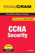
Figure 3.3 is a screenshot of the opening Cisco SDM screen on a Cisco 871 ISR.
Not all ISRs have enough flash to run the full SDM out of flash. If this is the case, you can either:
![]() Install Cisco SDM locally on a Windows PC.
Install Cisco SDM locally on a Windows PC.
![]() Run the Cisco SDM Express.
Run the Cisco SDM Express.
There are certain files that are required to run the Cisco SDM from the router’s flash file system. If these files don’t exist, they will need to be downloaded from Cisco. They come as part of a comprehensive download that also includes the files required to run the SDM applet from a PC workstation. Factory fresh routers from Cisco will have these files in flash. If they are not there, it means that someone has deleted them, perhaps because the organization’s security policy specifies that only the CLI can be used to configure the router.
Note
For more information about Cisco SDM and to download a package that contains the files necessary to run SDM from flash as well as the standalone SDM applet for use on a PC, navigate to http://www.cisco.com/go/sdm.
These files are needed to run Cisco SDM 2.2a and later from the router:
![]() sdmconfig-modelxxx.cfg: The default configuration for the model of ISR (for example: sdmconfig-2811.cfg)
sdmconfig-modelxxx.cfg: The default configuration for the model of ISR (for example: sdmconfig-2811.cfg)
![]() sdm.tar
sdm.tar
![]() es.tar (for SDM Express; can be deleted if only the SDM is being used)
es.tar (for SDM Express; can be deleted if only the SDM is being used)
![]() common.tar
common.tar
![]() home.shtml
home.shtml
![]() home.tar
home.tar
![]() wlanui.tar (if ISR has wireless interfaces)
wlanui.tar (if ISR has wireless interfaces)
This router does not have all the files necessary to run SDM:
cisco871#show flash
28672K bytes of processor board System flash (Intel Strataflash)
Directory of flash:/
1 -rwx 18924888 Mar 15 2008 16:51:09 -05:00 c870-
advipservicesk9-mz.124-15.T4.bin
2 -rwx 3179 Feb 14 2008 19:21:31 -05:00 sdmconfig-8xx.cfg
3 -rwx 1038 Feb 14 2008 19:21:10 -05:00 home.shtml
4 -rwx 112640 Feb 14 2008 19:21:46 -05:00 home.tar
5 -rwx 931840 Feb 14 2008 19:23:48 -05:00 es.tar
6 -rwx 1505280 Feb 14 2008 19:28:44 -05:00 common.tar
... output omitted ...
27611136 bytes total (4065280 bytes free)
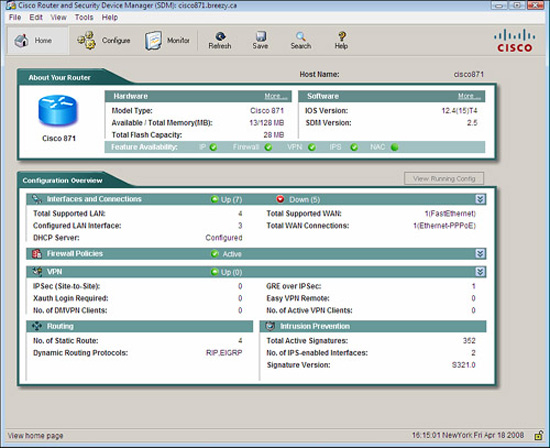
Because the router in the previous example doesn’t have enough flash memory, not all the files necessary to run the Cisco SDM are present. If you browse to https://router-ip-address, the Cisco SDM Express will launch instead.
On a new router, you browse to http://10.10.10.1 that is the default IP address of a new router. The initial configuration is completed by using the Cisco SDM Express Wizard. After the initial configuration of the router is complete, the Cisco SDM Express is no longer offered. Subsequent changes to the configuration use the full Cisco SDM.
Figure 3.4 illustrates the Cisco SDM Express.
After you have completed the router’s initial configuration with the SDM Express, you can now launch the SDM for more advanced configuration chores. There are two ways to launch the SDM, as follows:
![]() Cisco SDM on a PC. Use the Cisco SDM Launcher. The default location is Start->Programs->All Programs->Cisco Systems->Cisco SDM->Cisco SDM.
Cisco SDM on a PC. Use the Cisco SDM Launcher. The default location is Start->Programs->All Programs->Cisco Systems->Cisco SDM->Cisco SDM.
![]() Cisco SDM in Router Flash Memory. Open up a web browser and browse using either HTTP or HTTPS to the IP address that has been configured on the router.
Cisco SDM in Router Flash Memory. Open up a web browser and browse using either HTTP or HTTPS to the IP address that has been configured on the router.
Figure 3.5 shows both the SDM Launcher and using a web browser to access the Cisco SDM.

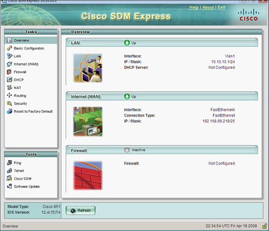
If you choose to use a web browser to launch SDM, it must meet the requirements in Table 3.1.
Note
Other java-enabled web browsers are likely to work, but Cisco TAC will support those listed in Table 3.1.
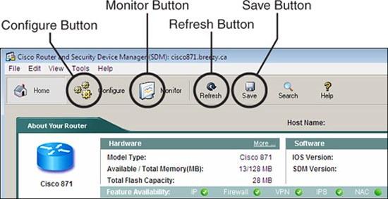
Accomplishing tasks on the Cisco SDM is done through buttons along the top of the SDM home page corresponding to different modes. Figure 3.6 illustrates these buttons.
In summary, these modes are as follows:
![]() Configure Mode. Provides its own task panel with buttons that represent the different configuration tasks and wizards for the novice.
Configure Mode. Provides its own task panel with buttons that represent the different configuration tasks and wizards for the novice.
![]() Monitor Mode. Provides its own task panel with views to the current status of the router.
Monitor Mode. Provides its own task panel with views to the current status of the router.
![]() Refresh. Updates the current running configuration on the router with the Cisco SDM.
Refresh. Updates the current running configuration on the router with the Cisco SDM.
![]() Save. Saves the running configuration to the startup configuration on the router (CLI: copy running-config startup-config).
Save. Saves the running configuration to the startup configuration on the router (CLI: copy running-config startup-config).
When you press the Configure mode button, a task panel appears. Pressing some of the buttons in this task panel will launch a smart wizard. Figure 3.7 shows some of the tasks that come up when you press the Configure mode button.

The following smart wizards are available from the tasks shown in Figure 3.7. Note that there is more than one wizard for each task. For example, in the Virtual Private Network (VPN) Wizards, you can configure site-to-site IPsec VPNs, remote-access Ipsec and Secure Sockets Layer (SSL) VPNs, Dynamic Multipoint VPNs (DMVPNs), and others. VPNs are discussed in Chapter 7, “Virtual Private Networks with IPsec.”
![]() Interfaces and Connections Wizards. Configure serial and LAN interfaces.
Interfaces and Connections Wizards. Configure serial and LAN interfaces.
![]() Firewall and ACL Wizards. Configure basic or advanced firewall.
Firewall and ACL Wizards. Configure basic or advanced firewall.
![]() VPN Wizards. Configure different types of VPNs.
VPN Wizards. Configure different types of VPNs.
![]() Security Audit Wizards. Perform a router security audit.
Security Audit Wizards. Perform a router security audit.
![]() Routing Wizards. Configure static routes and dynamic routing protocols.
Routing Wizards. Configure static routes and dynamic routing protocols.
![]() NAT Wizards. Configure basic and advanced NAT.
NAT Wizards. Configure basic and advanced NAT.
![]() Intrusion Prevention Wizards. Configure the IOS IPS.
Intrusion Prevention Wizards. Configure the IOS IPS.
![]() Quality of Service Wizards. Configure QoS to prioritize traffic as it flows through the router.
Quality of Service Wizards. Configure QoS to prioritize traffic as it flows through the router.
![]() NAC Wizards. Configure Network Admission Control policies.
NAC Wizards. Configure Network Admission Control policies.
If you scroll down one more button in the Configuration Task Panel (shown in Figure 3.7), you see a button marked Additional Tasks. Figure 3.8 shows the advanced configuration tasks that come up when you click the Additional Tasks button.

Here are the tasks that can be completed in the Additional Tasks menu illustrated in Figure 3.8:
![]() Router Properties. Some of the tasks that you can complete include configuring the router hostname, domain, password, date, and time.
Router Properties. Some of the tasks that you can complete include configuring the router hostname, domain, password, date, and time.
![]() Router Access. Some of the tasks that you can complete include role-based user access, management, and SSH.
Router Access. Some of the tasks that you can complete include role-based user access, management, and SSH.
![]() DNS and DDNS. Some of the tasks that you can complete include configuring Domain Name Service (DNS) and Dynamic DNS.
DNS and DDNS. Some of the tasks that you can complete include configuring Domain Name Service (DNS) and Dynamic DNS.
![]() ACLs. You can create and edit standard, extended, and named ACLs here.
ACLs. You can create and edit standard, extended, and named ACLs here.
![]() AAA. The major tasks that you can accomplish include configuring local and external authentication and authorization.
AAA. The major tasks that you can accomplish include configuring local and external authentication and authorization.
![]() Router Provisioning. The USB port can be configured here for secure device provisioning.
Router Provisioning. The USB port can be configured here for secure device provisioning.
![]() 802.1X. Port-based authentication through IEEE standard Extensible Authentication Protocol (EAP) using IEEE 802.1X can be configured here.
802.1X. Port-based authentication through IEEE standard Extensible Authentication Protocol (EAP) using IEEE 802.1X can be configured here.
In monitor mode, you can view important information about your router, including the firewall status, interface status, and active VPN connections. You can also view the router event log. This is illustrated in Figure 3.9.

Here is a summary of the information that can be viewed in monitor mode:
![]() Monitor Overview Window. Shows router status (CPU usage, flash memory usage, and flash usage) and a list of the error log entries.
Monitor Overview Window. Shows router status (CPU usage, flash memory usage, and flash usage) and a list of the error log entries.
![]() Interface Status. Shows whether interfaces are up or down, bandwidth utilization, and so on.
Interface Status. Shows whether interfaces are up or down, bandwidth utilization, and so on.
![]() Firewall Status. Shows a log with the number of access attempts that the router’s firewall has denied.
Firewall Status. Shows a log with the number of access attempts that the router’s firewall has denied.
![]() VPN Status. Statistics about active VPN connections.
VPN Status. Statistics about active VPN connections.
![]() QoS Status. Shows policy information on the interfaces.
QoS Status. Shows policy information on the interfaces.
![]() NAC Status. Shows the number of NAC sessions on the router.
NAC Status. Shows the number of NAC sessions on the router.
![]() Logging. Contains the router event log grouped by severity level.
Logging. Contains the router event log grouped by severity level.
There are many instances where simple password-based authentication will not be adequate. Certainly many security policies will dictate that both username and password will be required if for no other reason than that the person who logs in to the router needs to be identified (authenticated) and his activities need to be tracked (accounted). What users are allowed to do (authorization) is something else we can control if we know who they are in the first place. You can’t do all these things if the system simply uses passwords. Let’s first define AAA, and then quickly itemize Cisco’s four solutions. Then we’ll get back to configuring local database AAA on a Cisco router.
The next section contains a more formal definition of authentication, authorization, and accounting (AAA)—the functions that AAA servers perform.
The following list represents a simple definition of the three A’s in AAA.
![]() Authentication. Establishes who you are.
Authentication. Establishes who you are.
![]() Authorization. Now that we know who you are, we can establish what you can do and what you can access.
Authorization. Now that we know who you are, we can establish what you can do and what you can access.
![]() Accounting. Also, now that we know who you are, we can establish what you did, how long you did it, and how often you did it.
Accounting. Also, now that we know who you are, we can establish what you did, how long you did it, and how often you did it.
Note the heavy emphasis on you. (This isn’t a comment on society, by the way!) Clearly it all starts with authentication, because authorization and accounting would not be possible without establishing an individual’s identity first.
Cisco specifies two main reasons for implementing AAA on Cisco routers. These are outlined in the following list:
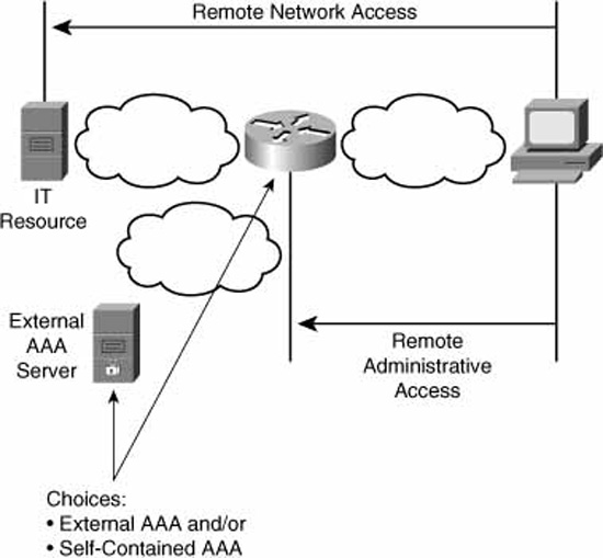
![]() Remote User Network Access. AAA is performed in support of IPsec and SSL VPN users and dial-up users before they are permitted access to an organization’s network.
Remote User Network Access. AAA is performed in support of IPsec and SSL VPN users and dial-up users before they are permitted access to an organization’s network.
![]() Administrative Access. AAA is performed before a user is permitted administrative access to a router (console, Telnet/SSH/HTTP, auxiliary).
Administrative Access. AAA is performed before a user is permitted administrative access to a router (console, Telnet/SSH/HTTP, auxiliary).
Let’s now look at how Cisco implements AAA for Cisco routers. There are two main categories of AAA implementations: local AAA (or “self-contained” AAA) and external AAA. These are outlined next:
![]() Self-Contained AAA. Local authentication on the router or other network access server (NAS) using a local username/password database. Essentially, the device is acting both as AAA client and server.
Self-Contained AAA. Local authentication on the router or other network access server (NAS) using a local username/password database. Essentially, the device is acting both as AAA client and server.
Exam Alert
The terms “Network Access Server (NAS)” and “AAA client” mean the same thing. Cisco favors the term “AAA client” mostly, but you will still see the term NAS here and there in Cisco literature.
![]() External Authentication. Authentication using an external Cisco Secure Access Control Server (ACS). There are three separate Cisco Secure ACS external AAA solutions:
External Authentication. Authentication using an external Cisco Secure Access Control Server (ACS). There are three separate Cisco Secure ACS external AAA solutions:
![]() Cisco Secure Access Control Server for Microsoft Windows Server.
Cisco Secure Access Control Server for Microsoft Windows Server.
![]() Cisco Secure ACS Express: An entry-level RADIUS and TACACS+ AAA 1U server appliance. Supports up to 50 AAA clients, as well as 350 unique user logons in a 24-hour period.
Cisco Secure ACS Express: An entry-level RADIUS and TACACS+ AAA 1U server appliance. Supports up to 50 AAA clients, as well as 350 unique user logons in a 24-hour period.
![]() Cisco Secure ACS Solution Engine: An appliance that supports many more AAA clients and unique user logons than Cisco Secure ACS Express.
Cisco Secure ACS Solution Engine: An appliance that supports many more AAA clients and unique user logons than Cisco Secure ACS Express.
Note
Readers who are familiar with AAA will note the heavy emphasis on Cisco solutions for external AAA. In reality, Cisco is one of many vendors of external AAA solutions. The market abounds with choices, including Microsoft IAS (Internet Authentication Service), FreeRadius (Open Source), and Livingston’s Steel-Belted Radius.
Recall from the “Two Reasons for Implementing AAA on Cisco Routers” section in this chapter that there are two types of access. Access to the router is called “remote administrative access”. Access through the router to networks beyond the router is called “remote network access.” Figure 3.10 illustrates this difference, as does Table 3.2, which defines how Cisco further categorizes these two main types of access.

There are four basic tasks to configuring local AAA (whether character or packet mode) on a router:
Task 1: Configure user accounts by creating a username/password database on the router.
Task 2: Enable AAA on the router.
Task 3: Configure AAA on the router, defining what type of remote access (administrative or network) AAA is to be performed and tying it to the username/password database.
Task 4: Verify and possibly troubleshoot the AAA configuration.
These tasks are the same whether you are using the Cisco SDM or the CLI. The following sections show the detailed steps in each task. Let’s perform the first three tasks using the SDM. The equivalent CLI command appears as a separate note with each task. Judge for yourself whether you prefer to use the GUI or the CLI.
Figure 3.11 illustrates the Add an Account dialog that you use to add a local user account on the router.

The separate steps to add a user per the dialog illustrated in Figure 3.11 are detailed next. The labels on Figure 3.11 correspond to the steps in the list:
-
Choose Configure->Additional Tasks->Router Access->User Accounts/View in the SDM.
-
Click Add to create a new user.
-
If you haven’t created views or lesser privilege levels, change this user’s Privilege Level to 15.
-
(Optional) If views have been defined, you can check the Associate a View with the user check box and select a view from the drop-down list.
-
Click OK and you’re done.
As we saw in the previous subsection, “Figure 3.12 illustrates the SDM dialog that is used to enable or disable AAA.
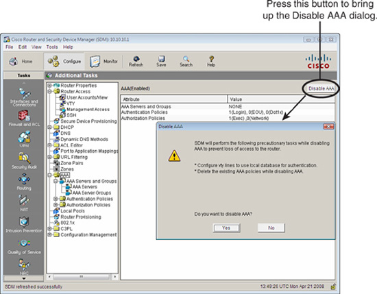
Choose Configure->Additional Tasks->AAA-> Enable (or Disable). Note the status of AAA. The GUI will tell you if it is enabled or disabled. If it is enabled, the button will be labeled Disable. If it is disabled, the button will be labeled Enable. If you click the Disable button, you will be warned that all AAA will be disabled. Recall that enabling AAA was a prerequisite for creating privilege levels and for views.
Figure 3.13 illustrates the basic steps required to configure AAA on the router.
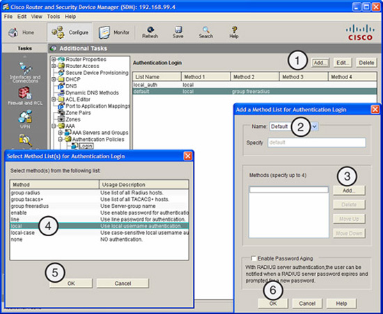
What follows are the basic steps required to configure AAA on the router. The labels on Figure 3.13 correspond with the numbers of the following steps:
-
Choose Configure->Additional Tasks->AAA->Authentication Policies->Login and click Add.
-
In the resulting “Add a Method List for Authentication Login” window, verify that Default is selected in the Name drop-down list.
-
From the “Select Method Lists(s) for Authentication Login” window, choose local.
-
Click the OK button on the Select Method List(s) for Authentication Login window.
-
Click the OK button on the Add a Method List for Authentication Login window to complete the task.
The debug aaa authentication CLI command helps you verify that AAA authentication is functioning. Note that in the following example, the terminal monitor command was necessary because this capture was made during a telnet session with the router. The output represents a successful login using the “default” AAA method:
CiscoISR#debug aaa authentication
AAA Authentication debugging is on
CiscoISR#terminal monitor
Apr 21 14:24:56.511: AAA/BIND(00000032): Bind i/f
Apr 21 14:24:56.511: AAA/AUTHEN/LOGIN (00000032): Pick method list
'default'
Let’s examine some additional CLI commands that help secure and verify an AAA configuration that uses the local database for authentication.
If you want to lock out any user after 10 failed login attempts for local AAA, you can issue this command:
aaa local authentication attempts max-fail 10
To identify local AAA users whose accounts have been locked out, you type in this command:
show aaa local user lockout
Here’s an example. It appears that the ISP user has been locked out. What were they doing working on the weekend anyway?
CiscoISR#show aaa local user lockout
Local-user Lock time
ispuser 14:28:49 UTC Sun Apr 20 2008
To clear (re-instate) all local AAA users who have been locked out, type in this command:
clear aaa local user lockout
If you want to clear a single local AAA user, you can use this form of the command, where ispuser is the locked-out user:
clear aaa local user lockout ispuser
To display detailed statistics of all logged-in users, you type in this command:
show aaa user all
The following command displays current sessions of users who have been authenticated, authorized, or accounted by the AAA module. It shows AAA sessions with their unique IDs:
show aaa sessions
Here’s an example of its output:
CiscoISR#show aaa sessions
Total sessions since last reload: 48
Session Id: 45
Unique Id: 50
User Name: admin
IP Address: 192.168.0.114
Idle Time: 0
CT Call Handle: 0
CiscoISR#
Recall that we have two choices for authentication in AAA:
![]() Self-contained AAA (local authentication)
Self-contained AAA (local authentication)
![]() External authentication
External authentication
This section covers authentication in the contexts of both self-contained AAA and external authentication. Authorization and accounting will not be covered. We modularize the basic tasks required to set up authentication in both self-contained AAA and external authentication, and along the way examine the strengths and weaknesses of the protocols RADIUS and TACACS+ and see how these protocols might be implemented for external authentication. Cisco strategic product for external AAA is Cisco Secure Access Control Server (ACS). We introduce Cisco Secure ACS, and leverage on its ease of use in describing and implementing an example external AAA solution for external authentication. We will also examine some CLI commands useful in verifying the configuration.
Note
There is a complete module on configuring AAA, including authentication authorization and accounting configuration in Cisco’s “Securing Networks with Routers and Switches” course. Because we focus on authentication and (later) authorization and accounting in this book, there is a danger that you may equate AAA with authentication. Remember that authentication is only the first A of three A’s in AAA!
There are two important differences or “deltas” in configuring external authentication as compared to local authentication:
![]() Delta 1: The username/password database is on the AAA server.
Delta 1: The username/password database is on the AAA server.
In the section titled “Tasks to Configure Local Database AAA on a Cisco Router,” we configured a local username/password database. With external AAA using Cisco Secure ACS, the database will be on the AAA server instead. (Although we might use the local database as a fallback should the AAA server fail or otherwise be unreachable.)
![]() Delta 2: You must set up communication between the AAA client and the AAA server.
Delta 2: You must set up communication between the AAA client and the AAA server.
When defining the authentication method (see “Task 3: Configuring AAA on the Router”), we won’t be using local AAA. This implies that we will have to set up a relationship between the AAA client (our router) and the AAA server (Cisco Secure ACS). As we will see, this involves the following AAA policy elements, as well as a way to group them:
![]() Choosing the AAA protocol, TACACS+, or RADIUS, to communicate between the client and server.
Choosing the AAA protocol, TACACS+, or RADIUS, to communicate between the client and server.
![]() Configuring the IP addresses and pre-shared key of the client and the server.
Configuring the IP addresses and pre-shared key of the client and the server.
Clearly Cisco Secure ACS is a deep topic all by itself. In this section, we will just scratch the surface of its features in the context of external AAA. We will also quickly compare RADIUS and TACACS+ protocols.
Cisco Secure ACS is most often used in networks where there are a large number of devices that need to be configured for AAA, and configuring local AAA on each device is thus made impractical and cumbersome. Here are some main reasons for implementing Cisco Secure ACS:
![]() Local authentication on a Cisco router does not scale well.
Local authentication on a Cisco router does not scale well.
![]() Cisco Secure ACS can create a central user and administrative access database for an entire network (see the following note).
Cisco Secure ACS can create a central user and administrative access database for an entire network (see the following note).
![]() Cisco Secure ACS works with many external databases, such as existing Active Directory, LDAP, and others.
Cisco Secure ACS works with many external databases, such as existing Active Directory, LDAP, and others.
Note
Perhaps the principle of “Separation of Services” is a guideline that your organization has formulated based on the material in Chapter 2, “Building a Secure Network Using Security Controls.”
Also, if your organization already has database repositories such as Active Directory, LDAP, or NDS, for example, Cisco Secure ACS can work with them. Why reinvent the wheel?
These are the features shared by all versions of Cisco Secure ACS:
![]() Web-based GUI
Web-based GUI
![]() Supports LDAP, Active Directory, Novell Directory Services (NDS), and ODBC databases
Supports LDAP, Active Directory, Novell Directory Services (NDS), and ODBC databases
![]() Rich accounting and user reporting features
Rich accounting and user reporting features
![]() Supports TACACS+ and RADIUS
Supports TACACS+ and RADIUS
![]() Tightly integrated with Cisco IOS router and Cisco VPN solutions
Tightly integrated with Cisco IOS router and Cisco VPN solutions
![]() Supports third-party OTPs
Supports third-party OTPs
![]() Access restrictions through dynamic quotas
Access restrictions through dynamic quotas
Figure 3.14 illustrates the home page for Cisco Secure ACS.

Unlike the Cisco Secure ACS Solution Engine and the Cisco Secure ACS Express, which are appliances, Cisco Secure ACS for Windows must be installed as an application on top of an existing Windows server.
The Cisco Secure ACS for Windows software requirements are as follows:
![]() Windows 2000 Server with Service Pack 4
Windows 2000 Server with Service Pack 4
![]() Windows 2000 Advanced Servers with Service Pack 4
Windows 2000 Advanced Servers with Service Pack 4
![]() Windows Server 2003 Standard Edition
Windows Server 2003 Standard Edition
![]() Windows Server 2003 Enterprise Edition
Windows Server 2003 Enterprise Edition
The Cisco Secure ACS for Windows hardware requirements are as follows:
![]() Pentium IV processor 1.8GHz or faster
Pentium IV processor 1.8GHz or faster
![]() 1GB of RAM
1GB of RAM
![]() Minimum 500MB to 1GB free disk space (more required if the database is on the same computer)
Minimum 500MB to 1GB free disk space (more required if the database is on the same computer)
![]() Minimum graphics resolution of 256 colors at 800x600 pixels
Minimum graphics resolution of 256 colors at 800x600 pixels
One immediate advantage of these devices is that the software comes pre-installed on a 1U, rack-mountable server form factor with a security-hardened Windows Server pre-installed. Table 3.3 compares the specifications and capabilities of these devices.

Whether you use Terminal Access Control Access Control Server Plus (TACACS+) or Remote Dial-in User Services (RADIUS) in your AAA implementation depends very much on what you need to accomplish. For example, the business needs of a large ISP might dictate that they choose the RADIUS protocol for their AAA solution because of the detailed accounting that is needed for billing dial-up and DSL users. On the other hand, if yours is an enterprise that has many groups of users accessing your core network devices, a centralized means to deploy granular authorization policies on a per-user or per-group basis may be required. In that case, TACACS+ would be a good solution. Table 3.4 represents a summary of some of the important differences between the two protocols.

Note
The Cisco default port numbers for RADIUS are UDP port 1645 for authentication / authorization (remember, these processes are combined in RADIUS; see Table 3.4) and UDP Port 1646 for accounting. This becomes important when working in a mixed-vendor environment where the non-Cisco NAS or AAA server may be using a different port number. This is a very common source of misconfiguration.
One of the main tasks in setting up Cisco Secure ACS is establishing communication between the AAA client(s) and the AAA server, Cisco Secure ACS. You must ensure that all the IP addresses and port numbers that are required to set up the TACACS+ or RADIUS link between the AAA devices are not blocked by other devices. You are not always lucky enough to have the devices physically co-located on the same IP subnet. Many security policies dictate that the AAA server be in a separate DMZ or other protected zone that implies that there may well be a firewall on the communication path between the AAA devices. (Firewalls are discussed in Chapter 5, “Using Cisco IOS Firewalls to Implement a Network Security Policy.”) There are some other prerequisites for Cisco Secure ACS of which you should be aware, as follows:
![]() Cisco IOS Release 11.2 or later must be installed on the Cisco AAA clients.
Cisco IOS Release 11.2 or later must be installed on the Cisco AAA clients.
![]() Non-IOS Cisco devices (or non-Cisco devices) must be configurable for standards-compliant RADIUS and/or TACACS+.
Non-IOS Cisco devices (or non-Cisco devices) must be configurable for standards-compliant RADIUS and/or TACACS+.
![]() A supported web browser must be installed on the Cisco ACS server (see the following note).
A supported web browser must be installed on the Cisco ACS server (see the following note).
Note
If you are planning to administer Cisco Secure ACS right on the server where it is installed, you can use a supported web browser to browse to the loopback IP address of the device at http://127.0.0.1:2002. Alternatively, you may administer ACS remotely by browsing to http://IP-address-of-ACS:2002 in a supported web browser. You will then be prompted to login with the username and password of an administrator. After you login on the ACS home page, the browser will be automatically redirected to another port number besides 2002. You will not be prompted for login credentials if you administer ACS right on the server, but you will be prompted for login credentials if you browse to the ACS home page from a remote workstation. The ability to administer ACS remotely would be useful if your security policy dictates that the AAA server can only be administered remotely. You should consider deploying ACS in a separate management VLAN.
We’re going to take a different approach from most texts to understanding how Cisco Secure ACS works. We start in a very task-oriented fashion. First, we focus on getting a working external AAA set up, and then we look at some of the features of Cisco Secure ACS that have not yet been examined, followed by some verification and debugging commands.
On Cisco Secure ACS, the starting point for setup will always be the navigation bar on the left side of the Cisco Secure ACS browser window. See Figure 3.15 for a screenshot. This screenshot was obtained by browsing to the Cisco Secure ACS home page using a web browser right on the server. Recall that when administering the ACS right on the hosting server, you browse to the local loopback IP address of the server.
The three main tasks for setting up external AAA are the following:
Task 1: Configure the AAA network (client and server).
Task 2: Set up users (server).
Task 3: Identify traffic to which AAA will be applied (client). This has three subtasks:
![]() Configuring authentication
Configuring authentication
![]() Configuring authorization
Configuring authorization
![]() Configuring accounting
Configuring accounting
Figure 3.16 shows where these three tasks occur The numbered labels in the figure match up with the task list. These general tasks would be followed regardless of the external AAA solution. Of course, we will model our solution after Cisco Secure ACS.

This section now goes on to discuss each of these tasks in more detail.
Setting up the AAA network essentially consists of setting up a relationship between two peers, the AAA client and the AAA server. The server peers on the client and the client peers on the server. They perform mutual authentication using a pre-shared key and using the same protocol (RADIUS or TACACS+) to exchange AAA information. These main elements must be completed on both the AAA client and the AAA server:
![]() Set up the protocol (RADIUS or TACACS+).
Set up the protocol (RADIUS or TACACS+).
![]() Specify the vendor of server (because port numbers used vary).
Specify the vendor of server (because port numbers used vary).
![]() Specify the IP address of the peer.
Specify the IP address of the peer.
![]() Specify the pre-shared key (pre-shared because both client and server use the same key).
Specify the pre-shared key (pre-shared because both client and server use the same key).
We perform these tasks first on the Cisco Secure ACS (the AAA server) and then on the IOS router (the AAA client).
Figure 3.17 illustrates the fields that need to be filled out in adding an AAA client in Cisco Secure ACS.
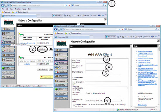
The steps to add a Cisco IOS router as an AAA client in Cisco Secure ACS are as follows:
-
Click the Network Configuration button on the navigation bar. The Network Configuration page appears.
-
Click Add Entry in the AAA Clients section.
-
Enter the client hostname in the AAA Client Hostname field. This is the name of the router that will be the AAA client from Cisco Secure ACS’s perspective.
Note
Here’s a tip. You should take care when choosing the name for the AAA client in the AAA Client hostname field referenced in Figure 3.17. The hostname is actually a unique connection name and should reflect the hostname of the router and the protocol name so that we can use both TACACS+ and RADIUS between the ACS and the router (that is, “hostname-tacacs” and “hostname-radius”).
-
Enter the router’s IP address in the AAA Client IP Address field.
-
Enter the pre-shared secret key in the Shared Secret field (remember this value, as you will need it when you set up the router for AAA).
-
Choose the correct AAA protocol in the Authenticate Using drop-down list.
-
Complete any other parameters as required.
-
Click Submit and Apply.
Now that we have configured the AAA client information on the AAA server, we can perform essentially the same steps, but now on the AAA client. Figure 3.18 illustrates the Add AAA Server dialog in Cisco SDM.

The following shows how to use SDM to add a TACACS+ AAA server to a Cisco IOS router (the CLI appears in a note at the end):
-
Open up the SDM, and choose Configure->Additional Tasks->AAA->AAA Servers and Groups->AAA Servers.
-
Click Add in the AAA Servers pane. The Add Server window appears. From the Server Type drop-down list, choose TACACS+.
-
Enter the IP address or hostname of the Cisco Secure ACS in the Server IP or Host field.
-
(Optional) You can choose to maintain a persistent connection to the server rather than opening and closing connections with every transaction. If this is what you want, check the Single Connection to Server (for CiscoSecure) check box. This is more efficient but only supported on Cisco Secure ACS version 1.0.1 or higher.
-
(Optional) If you want to set a timeout value specific to this server, enter a value in the Timeout (seconds) field in the Server-Specific Setup section. Otherwise, the router will use the value configured in the AAA Servers Global Settings window.
-
(Optional) If you want to set a pre-shared key specific to this server, enter a value in the New Key field in the Server-Specific Setup section. Otherwise, the router will use the value configured in the AAA Servers Global Settings window.
-
Click OK.
The users are set up on Cisco Secure ACS, as illustrated in Figure 3.19.

Open up Cisco Secure ACS and follow these steps to set up users. The labels on Figure 3.19 correspond with the step numbers:
-
In the navigation bar, click User Setup.
-
To create a new user, simply enter a username in the User field and click Add/Edit. (If this user already exists, you will be editing that user.)
-
Enter data in the fields to define the user account in the Edit pane. You will probably want to set the user’s password, as well as TACACS+ enable control, TACACS+ enable password, and TACACS+ shell authorized command. (Recall that command authorization is one of the features of TACACS+.)
-
Click Submit.
Note
What you see in the Edit pane in User Setup will depend on the interface configuration. “Interface” is this context means the user’s interface to ACS. The interface is set up when ACS is installed, but if you want to modify it, you may customize what fields are visible by choosing Interface Configuration->User Data Configuration from the navigation bar.
The identification of which traffic must have AAA service applied to it is done on the AAA client, which is the IOS router in our example. This task has three different elements to it, depending on which of the 3 A’s in AAA we want to apply to the traffic. Recall that we must perform authentication at a minimum because authorization and accounting depend on authentication: To repeat, here are the subtasks that we examine separately and in order in the subsequent sections:
![]() Configuring authentication
Configuring authentication
![]() Configuring authorization
Configuring authorization
![]() Configuring accounting
Configuring accounting
Once the network is set up as in Task 1, this group of AAA server settings is modular and can be used for a number of purposes. For example, once you have set up a TACACS+ server for authentication, it could be used for both remote administrative access and remote network access purposes.
Figure 3.20 illustrates the steps that are required to create an AAA login authentication policy on the AAA client.

Follow these steps to create an AAA login authentication policy using Cisco SDM on the IOS router, our AAA client:
-
Open up the Cisco SDM home page and choose Configure->Additional Tasks->AAA->Authentication Policies->Login.
-
Click Add from the Authentication Login pane.
-
From the Name drop-down list, choose User Defined to create a new authentication method.
-
In the Specify field, enter the authentication login method list name; MY_TACACS, for example.
-
To define the methods that this policy uses, click Add. The Select Method List(s) for Authentication Login window appears.
-
To add group tacacs+ to the method list, click OK. This will return you to the Add a Method List for Authentication Login window. The just-added method will now appear in this list.
-
To add a backup method for this policy, click Add. The Select Method List(s) for Authentication Login window appears.
-
This time, choose enable from the method list. This will cause the enable password to be used as the backup login authentication method.
-
To add enable to the method list, click OK. This will return you to the Add a Method List of Authentication Login window. Both group tacacs+ and enable should show up in the window. To make the enable password a back up to the group tacacs+ authentication method, make sure it appears below the group tacacs+ authentication method.
-
To add the authentication login method list, click OK.
The authentication login method list, like any policy, has no effect by itself once created. It must be applied to an entity on the device. This is a handy rule of thumb on Cisco devices. You create a policy; then you have to apply it somewhere. Keeping in mind that we have set up a login authentication method (and using your intuition), this authentication method most likely needs to be applied to one of the line interfaces on the router. In this scenario, we apply the authentication method MY_TACACS, to the five default vty lines on the router.
The Cisco SDM dialog to apply the authentication method MY_TACACS to the vtys is illustrated in Figure 3.21.

To apply the authentication method to the vtys using the SDM, follow these steps:
-
Choose Configure->Additional Tasks->Router Access->VTY->Edit.
-
In the Edit VTY Lines window, choose the MY_TACACS login authentication method from the Authentication Policy drop-down list.
-
Click OK to deliver the commands to the router.
The CLI command to apply the authentication policy to the vtys would look like this:
CiscoISR#configure terminal
CiscoISR(config)#line vty 0 4
CiscoISR(config-line)#login authentication MY_TACACS
Now when administrators log in to the Cisco IOS router via the vtys, they will be prompted for a username and password. These credentials will be validated using the TACACS+ protocol against the user database on the Cisco Secure ACS. It should be noted that this will not affect SDM login, only access via Telnet or SSH.
Thus, we have completed the tasks to perform the first A in AAA, authentication. Let’s turn our attention to the second A in AAA, authorization. Leveraging on our TACACS+ server, we will:
![]() First, create and apply an authorization policy for exec (character mode).
First, create and apply an authorization policy for exec (character mode).
![]() Second, create and apply an authorization policy for network (packet mode).
Second, create and apply an authorization policy for network (packet mode).
The method to create an exec authorization policy is illustrated in Figure 3.22.

Note
The following steps assume that we have already configured an authorization policy on the Cisco Secure ACS (we have!). If you create and apply an AAA exec authorization policy before you have configured one on the authorization server, you will lock yourself out of the router. This is very embarrassing.
Using the Cisco SDM and starting at the home page, follow these steps to create and apply the default authorization method list for exec (character mode) access. Figure 3.22 is labeled to correspond to the numbers in the following list of steps:
-
Choose Configure->Additional Tasks->AAA->Authorization Polices->Exec.
-
Click Add in the Exec Authorization pane.
-
Choose Default from the Name drop-down list in the Add a Method List for Exec Authorization window.
-
To define the methods that this policy uses, click Add.
-
Choose group tacacs+ from the method list in the Select Method List(s) for Exec Authorization window.
-
Click OK on the next two windows in succession to return to the Exec Authorization pane.
Now, when administrators access the CLI, they will only be allowed to execute the commands they are authorized to use as defined in the user’s authorization policy on the Cisco Secure ACS.
Let’s now turn our attention to defining what a user is authorized to do on the network segment protected by the Cisco IOS router.
The method to create a network authorization policy is illustrated in Figure 3.23.

Starting on the Cisco SDM home page, complete the following steps to configure the default authorization method list for network (packet mode) access. Figure 3.23 has labels corresponding to the numbers of the following steps:
-
Choose Configure->Additional Tasks->AAA Authorization Policies->Network.
-
Click Add in the Network Authorization pane.
-
Choose Default from the Name drop-down list in the Add a Method List for Network Authorization window.
-
To define the methods that this policy uses, click Add.
-
Choose group tacacs+ from the method list in the Select Method List(s) for Network Authorization window.
-
Click OK on the next two windows in succession to return to the Network Authorization pane.
When properly configured, Cisco Secure ACS acts as a central repository of tracked events as they occur on the network. For example, our comprehensive network security policy might stipulate that all failed login attempts to (and through) the routers are to be tracked, with detailed information about the attempt such as user credentials, time of day, and date. Without keeping track of this information, we might not be able to provide data to aid in a forensic investigation should our network be compromised or otherwise attacked.
As with authentication and authorization, you must first create a method list (the policy), and then apply it to the right entity. As we have seen, method lists can be multi-purpose, so a method list may support all three As in AAA.
AAA involves six different types of accounting, as follows:
![]() Network. Runs accounting for all network-related service requests, including Serial Line Internet Protocol (SLIP), PPP, PPP Network Control Protocols (NCPs), and AppleTalk Remote Access Protocol (ARAP).
Network. Runs accounting for all network-related service requests, including Serial Line Internet Protocol (SLIP), PPP, PPP Network Control Protocols (NCPs), and AppleTalk Remote Access Protocol (ARAP).
![]() Connection. Provides information about all outbound connections made from the network access server, such as Telnet.
Connection. Provides information about all outbound connections made from the network access server, such as Telnet.
![]() Exec. Runs accounting for the EXEC shell session.
Exec. Runs accounting for the EXEC shell session.
![]() System. Performs accounting for all system-level events not associated with users, such as reloads.
System. Performs accounting for all system-level events not associated with users, such as reloads.
![]() Commands. Runs accounting for all commands at the specified privilege level.
Commands. Runs accounting for all commands at the specified privilege level.
![]() Resource. Performs accounting for resource use by remote users of the system. (The command syntax for setting resource accounting is different than the other items listed.)
Resource. Performs accounting for resource use by remote users of the system. (The command syntax for setting resource accounting is different than the other items listed.)
These different types of accounting are reflected in the command syntax of the aaa accounting command:
aaa accounting { system | network | exec | connection | commands level }
{default | list-name} {start-stop | stop-only | none} [method1 [method2]]
Use the following form of the command to perform accounting for system resource use by remote users:
aaa accounting resource method-list start-stop [broadcast] group groupname
To set up accounting using the CLI, follow these basic steps (with examples):
-
Create an accounting method list and enable accounting.
CiscoISR(config)#aaa accounting connection default start-stop group
tacacs+ -
Enter line configuration mode or interface configuration mode for the lines or interface to which the accounting method list will be applied.
CiscoISR(config)#line vty 0 4
-
Apply the account method list to the line(s) or interface(s).
CiscoISR(config-line)#accounting connection default
Here are a handful of useful commands for troubleshooting and debugging local AAA, RADIUS, and TACACS+.
For a high-level view of login activity, use the following CLI command:
debug aaa authentication
Here is an example of the output of the debug aaa authentication command. The highlighted output indicates that someone logged on to this ISR and that the authentication method used was local_auth:
ciscoISR#debug aaa authentication
AAA Authentication debugging is on
443521: Aug 7 08:56:19.498 NewYork: AAA/BIND(000032C8): Bind i/f
443522: Aug 7 08:56:20.110 NewYork: AAA/BIND(000032C9): Bind i/f
443523: Aug 7 08:56:22.117 NewYork: AAA/BIND(000032CA): Bind i/f
443524: Aug 7 08:56:24.628 NewYork: AAA/BIND(000032CB): Bind i/f
443525: Aug 7 08:56:24.628 NewYork: AAA/AUTHEN/LOGIN (000032CB): Pick
method list 'local_auth'
For more detailed debugging of TACACS+ in particular, use the following CLI command:
debug tacacs
For even more detailed information about the TACACS+ helper process, you can use the following CLI command. Be careful with its use, because it generates copious amounts of output.
debug tacacs event
For more detailed debugging of RADIUS in particular, use the following CLI command:
debug radius
For even more detailed information about the RADIUS helper process, you can use the following CLI command. Be careful with its use, because it generates copious amounts of output:
debug radius event
Here is a snapshot of a partial configuration with the commands in Tasks 1, 2, and 3 for setting up external AAA and including the preceding AAA accounting configuration. If the commands don’t make sense, review them in the preceding sections:
aaa new-model
!
aaa authentication login MY_TACACS tacacs+ local
aaa authorization exec tacacs+
aaa authorization network tacacs+
aaa accounting connection default start-stop group tacacs+
!
tacacs-server host 192.168.99.133
tacacs-server key cisco123
!
line vty 0 4
login authentication MY_TACACS
accounting connection default