
In this chapter we will look at the design of simple PIC18 microcontroller-based projects, with the idea of becoming familiar with basic interfacing techniques and learning how to use the various microcontroller peripheral registers. We will look at the design of projects using LEDs, push-button switches, keyboards, LED arrays, sound devices, and so on, and we will develop programs in C language using the mikroC compiler. The hardware is designed on a low-cost breadboard, but development kits such as BIGPIC4 can be used for these projects. We will start with very simple projects and proceed to more complex ones. It is recommended that the reader moves through the projects in their given order. The following are provided for each project:
Description of the program
Description of the hardware
Circuit diagram
Algorithm description (in PDL)
Program listing
Suggestions for further development
The program’s algorithm can be described in a variety of graphic and text-based methods, some of the common ones being a flow diagram, a structure chart, and program description language. In this book we are using program description language (PDL).
Program description language (PDL) is free-format English-like text which describes the flow of control in a program. PDL is not a programming language but rather is a tool which helps the programmer to think about the logic of the program before the program has been developed. Commonly used PDL keywords are described as follows.
Every PDL program description (or subprogram) should begin with a START keyword and terminate with an END keyword. The keywords in a PDL code should be highlighted in bold to make the code more clear. It is also a good practice to indent program statements between PDL keywords in order to enhance the readability of the code.
For normal sequencing in a program, write the statements as short English text as if you are describing the program.
Use IF, THEN, ELSE, and ENDIF keywords to describe the flow of control in a program.
Use Do and ENDDO keywords to show iteration in the PDL code.
To create an unconditional loop in a program we can write:
Turn on LED
DO 10 times
    Set clock to 1
    Wait for 10ms
    Set clock to 0
ENDDO
A variation of the DO-ENDDO construct is to use other keywords like DO-FOREVER, DO-UNTIL, etc. as shown in the following examples.
To create a conditional loop in a program we can write:
Turn off buzzer
IF switch = 1 THEN
    DO UNTIL Port 1 = 1
         Turn on LED
         Wait for 10ms
         Read Port 1
    ENDDO
ENDIF
The following construct can be used when an endless loop is required:
DO FOREVER
    Read data from Port 1
    Send data to PORT 2
    Wait for 1 second
ENDDO
REPEAT-UNTIL is another control construct used in PDL codes. In the following example the program waits until a switch value is equal to 1.
In this project eight LEDs are connected to PORTC of a PIC18F452-type microcontroller, and the microcontroller is operated from a 4MHz resonator. When power is applied to the microcontroller (or when the microcontroller is reset), the LEDs turn ON alternately in an anticlockwise manner where only one LED is ON at any time. There is a one-second delay between outputs so the LEDs can be seen turning ON and OFF.
An LED can be connected to a microcontroller output port in two different modes: current sinking and current sourcing.
As shown in Figure 6.1, in current sinking mode the anode leg of the LED is connected to the +5V supply, and the cathode leg is connected to the microcontroller output port through a current limiting resistor.

The voltage drop across an LED varies between 1.4V and 2.5V, with a typical value of 2V. The brightness of the LED depends on the current through the LED, and this current can vary between 8 and 16mA, with a typical value of 10mA.
The LED is turned ON when the output of the microcontroller is at logic 0 so the current flows through the LED. Assuming the microcontroller output voltage is about 0.4V when the output is low, we can calculate the value of the required resistor as follows:
where
VS is the supply voltage (5V)
VLED is the voltage drop across the LED (2V)
VL is the maximum output voltage when the output port is low (0.4V)
ILED is the current through the LED (10mA)
Substituting the values into Equation (6.1) we get,
The nearest physical resistor is 270 ohms.
As shown in Figure 6.2, in current sourcing mode the anode leg of the LED is connected to the microcontroller output port and the cathode leg is connected to the ground through a current limiting resistor.

In this mode the LED is turned ON when the microcontroller output port is at logic 1 (i.e., +5V). In practice, the output voltage is about 4.85V and the value of the resistor can be determined as:
where
VO is the output voltage of the microcontroller port when at logic 1 (+4.85V).
Thus, the value of the required resistor is:
The nearest physical resistor is 290 ohm.
The circuit diagram of the project is shown in Figure 6.3. LEDs are connected to PORTC in current sourcing mode with eight 290-ohm resistors. A 4MHz resonator is connected between the OSC1 and OSC2 pins. Also, an external reset push button is connected to the MCLR input to reset the microcontroller when required.

The PDL of this project is very simple and is given in Figure 6.4.
The program is named as LED1.C, and the program listing is given in Figure 6.5. At the beginning of the program PORTC pins are configured as outputs by setting TRISC = 0. Then an endless for loop is formed, and the LEDs are turned ON alternately in an anticlockwise manner to create a chasing effect. The program checks continuously so that when LED 7 is turned ON, the next LED to be turned ON is LED 0.
Table 6.5. Program listing
/*********************************************************************** CHASING LEDS ============In this project 8 LEDs are connected to PORTC of a PIC18F452 microcontrollerand the microcontroller is operated from a 4MHz resonator. The program turns onthe LEDs in an anti-clockwise manner with one second delay between each output.The net result is that the LEDs seem to be chasing each other.Author: Dogan IbrahimDate: July 2007File: LED1.C************************************************************************/void main(){ unsigned char J = 1; TRISC = 0; for(;;) // Endless loop { PORTC = J; // Send J to PORTC Delay_ms(1000); // Delay 1 second J = J << 1; // Shift left J if(J == 0) J = 1; // If last LED, move to first LED }} |
This program can be compiled using the mikroC compiler. Project settings should be configured to 4MHz clock, XT crystal mode, and WDT OFF. The HEX file (LED1.HEX) should be loaded to the PIC18F452 microcontroller using either an in-circuit debugger or a programming device.
The project can be modified such that the LEDs chase each other in both directions. For example, if the LEDs are moving in an anticlockwise direction, the direction can be changed so that when LED RB7 is ON the next LED to turn ON is RB6, when RB6 is ON the next is RB5, and so on.
This is a simple dice project based on LEDs, a push-button switch, and a PIC18F452 microcontroller operating with a 4MHz resonator. The block diagram of the project is shown in Figure 6.6.
As shown in Figure 6.7, the LEDs are organized such that when they turn ON, they indicate numbers as on a real dice. Operation of the project is as follows: The LEDs are all OFF to indicate that the system is ready to generate a new number. Pressing the switch generates a random number between 1 and 6 which is displayed on the LEDs for 3 seconds. After 3 seconds the LEDs turn OFF again.

The circuit diagram of the project is shown in Figure 6.8. Seven LEDs representing the faces of a dice are connected to PORTC of a PIC18F452 microcontroller in current sourcing mode using 290-ohm current limiting resistors. A push-button switch is connected to bit 0 of PORTB (RB0) using a pull-up resistor. The microcontroller is operated from a 4MHz resonator connected between pins OSC1 and OSC2. The microcontroller is powered from a +9V battery, and a 78L05-type voltage regulator IC is used to obtain the +5V supply required for the microcontroller.

The operation of the project is described in PDL in Figure 6.9. At the beginning of the program PORTC pins are configured as outputs and bit 0 of PORTB (RB0) is configured as input. The program then executes in a loop continuously and increments a variable between 1 and 6. The state of the push-button switch is checked and when the switch is pressed (switch output at logic 0), the current number is sent to the LEDs. A simple array is used to find out the LEDs to be turned ON corresponding to the dice number.
Table 6.9. PDL of the project
START Create DICE table Configure PORTC as outputs Configure RB0 as input Set J = 1 DO FOREVER IF button pressed THEN Get LED pattern from DICE table Turn ON required LEDs Wait 3 seconds Set J = 0 Turn OFF all LEDs ENDIF Increment J IF J = 7 THEN Set J = 1 ENDIF ENDDOEND |
Table 6.1 gives the relationship between a dice number and the corresponding LEDs to be turned ON to imitate the faces of a real dice. For example, to display number 1 (i.e., only the middle LED is ON), we have to turn on D4. Similarly, to display number 4, the LEDs to turn ON are D1, D3, D5, and D7.
The relationship between the required number and the data to be sent to PORTC to turn on the correct LEDs is given in Table 6.2. For example, to display dice number 2, we have to send hexadecimal 0 × 22 to PORTC. Similarly, to display number 5, we have to send hexadecimal 0 × 5D to PORTC, and so on.
The program is called LED2.C, and the program listing is given in Figure 6.10. At the beginning of the program Switch is defined as bit 0 of PORTB, and Pressed is defined as 0. The relationships between the dice numbers and the LEDs to be turned on are stored in an array called DICE. Variable J is used as the dice number. Variable Pattern is the data sent to the LEDs. Program then enters an endless for loop where the value of variable J is incremented very fast between 1 and 6. When the push-button switch is pressed, the LED pattern corresponding to the current value of J is read from the array and sent to the LEDs. The LEDs remain in this state for 3 seconds (using function Delay_ms with the argument set to 3000ms), after which they all turn OFF. The system is then ready to generate a new dice number.
Table 6.10. Program listing
/*************************************************************** SIMPLE DICE ===========In this project 7 LEDs are connected to PORTC of a PIC18F452 microcontrollerand the microcontroller is operated from a 4MHz resonator. The LEDs are organizedas the faces of a real dice. When a push-button switch connected to RB0 is pressed adice pattern is displayed on the LEDs. The display remains in this state for 3 secondsand after this period the LEDs all turn OFF to indicate that the system is ready for thebutton to be pressed again.Author: Dogan IbrahimDate: July 2007File: LED2.C***************************************************************/#define Switch PORTB.F0#define Pressed 0void main(){ unsigned char J = 1; unsigned char Pattern; unsigned char DICE[] = {0,0x08,0x22,0x2A,0x55,0x5D,0x77}; TRISC = 0; // PORTC outputs TRISB = 1; // RB0 input PORTC = 0; // Turn OFF all LEDs for(;;) // Endless loop { if(Switch == Pressed) // Is switch pressed ? { Pattern = DICE[J]; // Get LED pattern PORTC = Pattern; // Turn on LEDs Delay_ms(3000); // Delay 3 second PORTC = 0; // Turn OFF all LEDs J = 0; // Initialise J } J++; // Increment J if(J == 7) J = 1; // Back to 1 if > 6 }} |
In the preceding project the value of variable J changes very fast among the numbers between 1 and 6, so we can say that the numbers generated are random (i.e., new numbers do not depend on the previous numbers).
A pseudorandom number generator function can also be used to generate the dice numbers. The modified program listing is shown in Figure 6.11. In this program a function called Number generates the dice numbers. The function receives the upper limit of the numbers to be generated (6 in this example) and also a seed value which defines the number set to be generated. In this example, the seed is set to 1. Every time the function is called, a number between 1 and 6 is generated.
Table 6.11. Dice program using a pseudorandom number generator
/************************************************************* SIMPLE DICE ===========In this project 7 LEDs are connected to PORTC of a PIC18F452 microcontrollerand the microcontroller is operated from a 4MHz resonator. The LEDs are organizedas the faces of a real dice. When a push-button switch connected to RB0 is pressed adice pattern is displayed on the LEDs. The display remains in this state for 3 secondsand after this period the LEDs all turn OFF to indicate that the system is ready for thebutton to be pressed again.In this program a pseudorandom number generator function isused to generate the dice numbers between 1 and 6.Author: Dogan IbrahimDate: July 2007File: LED3.C**************************************************************/#define Switch PORTB.F0#define Pressed 0//// This function generates a pseudo random integer number// between 1 and Lim//unsigned char Number(int Lim, int Y){ unsigned char Result; static unsigned int Y; Y = (Y * 32719 + 3) % 32749; Result = ((Y % Lim) + 1); return Result;}//// Start of MAIN program//void main(){ unsigned char J,Pattern,Seed = 1; unsigned char DICE[] = {0,0x08,0x22,0x2A,0x55,0x5D,0x77}; TRISC = 0; // PORTC outputs TRISB = 1; // RB0 input PORTC = 0; // Turn OFF all LEDs for(;;) // Endless loop |
The operation of the program is basically same as in Figure 6.10. When the push-button switch is pressed, function Number is called to generate a new dice number between 1 and 6, and this number is used as an index in array DICE in order to find the bit pattern to be sent to the LEDs.
This project is similar to Project 2, but here a pair of dice are used—as in many dice games such as backgammon—instead of a single dice.
The circuit shown in Figure 6.8 can be modified by adding another set of seven LEDs for the second dice. For example, the first set of LEDs can be driven from PORTC, the second set from PORTD, and the push-button switch can be connected to RB0 as before. Such a design requires fourteen output ports just for the LEDs. Later on we will see how the LEDs can be combined in order to reduce the input/output requirements. Figure 6.12 shows the block diagram of the project.
The circuit diagram of the project is shown in Figure 6.13. The circuit is basically same as in Figure 6.8, with the addition of another set of LEDs connected to PORTD.
The operation of the project is very similar to that for Project 2. Figure 6.14 shows the PDL for this project. At the beginning of the program the PORTC and PORTD pins are configured as outputs, and bit 0 of PORTB (RB0) is configured as input. The program then executes in a loop continuously and checks the state of the push-button switch. When the switch is pressed, two pseudorandom numbers between 1 and 6 are generated, and these numbers are sent to PORTC and PORTD. The LEDs remain at this state for 3 seconds, after which all the LEDs are turned OFF to indicate that the push-button switch can be pressed again for the next pair of numbers.
Table 6.14. PDL of the project
START Create DICE table Configure PORTC as outputs Configure PORTD as outputs Configure RB0 as input DO FOREVER IF button pressed THEN Get a random number between 1 and 6 Find bit pattern Turn ON LEDs on PORTC Get second random number between 1 and 6 Find bit pattern Turn on LEDs on PORTD Wait 3 seconds Turn OFF all LEDs ENDIF ENDDO END |
The program is called LED4.C, and the program listing is given in Figure 6.15. At the beginning of the program Switch is defined as bit 0 of PORTB, and Pressed is defined as 0. The relationships between the dice numbers and the LEDs to be turned on are stored in an array called DICE, as in Project 2. Variable Pattern is the data sent to the LEDs. Program enters an endless for loop where the state of the push-button switch is checked continuously. When the switch is pressed, two random numbers are generated by calling function Number. The bit patterns to be sent to the LEDs are then determined and sent to PORTC and PORTD. The program then repeats inside the endless loop, checking the state of the push-button switch.
Table 6.15. Program listing
/************************************************************* TWO DICE ========In this project 7 LEDs are connected to PORTC of a PIC18F452 microcontroller and7 LEDs to PORTD. The microcontroller is operated from a 4MHz resonator.The LEDs are organized as the faces of a real dice. When a push-button switchconnected to RB0 is pressed a dice pattern is displayed on the LEDs. The displayremains in this state for 3 seconds and after this period the LEDs all turn OFF toindicate that the system is ready for the button to be pressed again.In this program a pseudorandom number generator function isused to generate the dice numbers between 1 and 6.Author: Dogan IbrahimDate: July 2007File: LED4.C*************************************************************/#define Switch PORTB.F0#define Pressed 0//// This function generates a pseudo random integer number// between 1 and Lim//unsigned char Number(int Lim, int Y){ unsigned char Result; static unsigned int Y; Y = (Y * 32719 + 3) % 32749; Result = ((Y % Lim) + 1); return Result;}//// Start of MAIN program//void main(){ unsigned char J,Pattern,Seed = 1; unsigned char DICE[] = {0,0x08,0x22,0x2A,0x55,0x5D,0x77}; TRISC = 0; // PORTC are outputs TRISD = 0; // PORTD are outputs TRISB = 1; // RB0 input PORTC = 0; // Turn OFF all LEDs PORTD = 0; // Turn OFF all LEDs |
This project is similar to Project 3, but here LEDs are shared, which uses fewer input/output pins.
The LEDs in Table 6.1 can be grouped as shown in Table 6.3. Looking at this table we can say that:
D4 can appear on its own
D2 and D6 are always together
D1 and D3 are always together
D5 and D7 are always together
Thus, we can drive D4 on its own and then drive the D2,D6 pair together in series, the D1,D3 pair together in series, and also the D5,D7 pair together in series. (Actually, we could share D1,D3,D5,D7 but this would require 8 volts to drive if the LEDs are connected in series. Connecting them in parallel would call for even more current, and a driver IC would be required.) Altogether, four lines are needed to drive the seven LEDs of each dice. Thus, a pair of dice can easily be driven from an 8-bit output port.
The circuit diagram of the project is shown in Figure 6.16. PORTC of a PIC18F452 microcontroller is used to drive the LEDs as follows:
RC0 drives D2,D6 of the first dice
RC1 drives D1,D3 of the first dice
RC2 drives D5,D7 of the first dice
RC3 drives D4 of the first dice
RC4 drives D2,D6 of the second dice
RC5 drives D1,D3 of the second dice
RC6 drives D5,D7 of the second dice
RC7 drives D4 of the second dice
Since two LEDs are being driven on some outputs, we can calculate the required value of the current limiting resistors. Assuming that the voltage drop across each LED is 2V, the current through the LED is 10mA, and the output high voltage of the microcontroller is 4.85V, the required resistors are:
We will choose 100-ohm resistors.
We now need to find the relationship between the dice numbers and the bit pattern to be sent to the LEDs for each dice. Table 6.4 shows the relationship between the first dice numbers and the bit pattern to be sent to port pins RC0-RC3. Similarly, Table 6.5 shows the relationship between the second dice numbers and the bit pattern to be sent to port pins RC4-RC7.
We can now find the 8-bit number to be sent to PORTC to display both dice numbers as follows:
Get the first number from the number generator, call this P
Index the DICE table to find the bit pattern for low nibble (i.e., L = DICE[P])
Get the second number from the number generator, call this P
Index the DICE table to find the bit pattern for high nibble (i.e., U = DICE[P])
Multiply high nibble by 16 and add low nibble to find the number to be sent to PORTC (i.e., R = 16*U + L), where R is the 8-bit number to be sent to PORTC to display both dice values.
The operation of this project is very similar to that of Project 2. Figure 6.17 shows the PDL of the project. At the beginning of the program the PORTC pins are configured as outputs, and bit 0 of PORTB (RB0) is configured as input. The program then executes in a loop continuously and checks the state of the push-button switch. When the switch is pressed, two pseudorandom numbers between 1 and 6 are generated, and the bit pattern to be sent to PORTC is found by the method just described. This bit pattern is then sent to PORTC to display both dice numbers at the same time. The display shows the dice numbers for 3 seconds, and then all the LEDs turn OFF to indicate that the system is waiting for the push-button to be pressed again to display the next set of numbers.
Table 6.17. PDL of the project
START Create DICE table Configure PORTC as outputs Configure RB0 as input DO FOREVER IF button pressed THEN Get a random number between 1 and 6 Find low nibble bit pattern Get second random number between 1 and 6 High high nibble bit pattern Calculate data to be sent to PORTC Wait 3 seconds Turn OFF all LEDs ENDIF ENDDOEND |
The program is called LED5.C, and the program listing is given in Figure 6.18. At the beginning of the program Switch is defined as bit 0 of PORTB, and Pressed is defined as 0. The relationships between the dice numbers and the LEDs to be turned on are stored in an array called DICE as in Project 2. Variable Pattern is the data sent to the LEDs. The program enters an endless for loop where the state of the push-button switch is checked continuously. When the switch is pressed, two random numbers are generated by calling function Number. Variables L and U store the lower and higher nibbles of the bit pattern to be sent to PORTC. The bit pattern to be sent to PORTC is then determined using the method described in the Project Hardware section and stored in variable R. This bit pattern is then sent to PORTC to display both dice numbers at the same time. The dice numbers are displayed for 3 seconds, after which the LEDs are turned OFF to indicate that the system is ready.
Table 6.18. Program listing
/*************************************************************** TWO DICE - USING FEWER I/O PINS ==============================In this project LEDs are connected to PORTC of a PIC18F452 microcontrollerand the microcontroller is operated from a 4MHz resonator. The LEDs areorganized as the faces of a real dice. When a push-button switch connected toRB0 is pressed a dice pattern is displayed on the LEDs. The display remainsin this state for 3 seconds and after this period the LEDs all turn OFF to indicatethat the system is ready for the button to be pressed again.In this program a pseudorandom number generator function isused to generate the dice numbers between 1 and 6.Author: Dogan IbrahimDate: July 2007File: LED5.C***************************************************************/#define Switch PORTB.F0#define Pressed 0//// This function generates a pseudo random integer number// between 1 and Lim//unsigned char Number(int Lim, int Y){ unsigned char Result; static unsigned int Y; Y = (Y * 32719 + 3) % 32749; Result = ((Y % Lim) + 1); return Result;}//// Start of MAIN program//void main(){ unsigned char J,L,U,R,Seed = 1; unsigned char DICE[] = {0,0x08,0x01,0x09,0x06,0x0E,0x07}; TRISC = 0; // PORTC are outputs TRISB = 1; // RB0 input PORTC = 0; // Turn OFF all LEDs for(;;) // Endless loop |
The program given in Figure 6.18 can made more efficient by combining the two dice nibbles into a single table value as described here.
There are thirty-six possible combinations of the two dice values. Referring to Table 6.4, Table 6.5, and Figure 6.16, we can create Table 6.6 to show all the possible two-dice values and the corresponding numbers to be sent to PORTC.
Table 6.6. Two-dice combinations and the number to be sent to PORTC
Dice numbers | PORTC value | Dice numbers | PORTC value |
|---|---|---|---|
1,1 | 0 × 88 | 4,1 | 0 × 86 |
1,2 | 0 × 18 | 4,2 | 0 × 16 |
1,3 | 0 × 98 | 4,3 | 0 × 96 |
1,4 | 0 × 68 | 4,4 | 0 × 66 |
1,5 | 0 × E8 | 4,5 | 0 × E6 |
1,6 | 0 × 78 | 4,6 | 0 × 76 |
2,1 | 0 × 81 | 5,1 | 0 × 8E |
2,2 | 0 × 11 | 5,2 | 0 × 1E |
2,3 | 0 × 91 | 5,3 | 0 × 9E |
2,4 | 0 × 61 | 5,4 | 0 × 6E |
2,5 | 0 × E1 | 5,5 | 0 × EE |
2,6 | 0 × 71 | 5,6 | 0 × 7E |
3,1 | 0 × 89 | 6,1 | 0 × 87 |
3,2 | 0 × 19 | 6,2 | 0 × 17 |
3,3 | 0 × 99 | 6,3 | 0 × 97 |
3,4 | 0 × 69 | 6,4 | 0 × 67 |
3,5 | 0 × E9 | 6,5 | 0 × E7 |
3,6 | 0 × 79 | 6,6 | 0 × 77 |
The modified program (program name LED6.C) is given in Figure 6.19. In this program array DICE contains the thirty-six possible dice values. The program enters an endless for loop, and inside this loop the state of the push-button switch is checked. Also, a variable is incremented from 1 to 36. When the button is pressed, the value of this variable is used as an index to array DICE to determine the bit pattern to be sent to PORTC. As before, the program displays the dice numbers for 3 seconds and then turns OFF all LEDs to indicate that it is ready.
Table 6.19. Modified program
/************************************************************* TWO DICE - USING FEWER I/O PINS =============================In this project LEDs are connected to PORTC of a PIC18F452 microcontrollerand the microcontroller is operated from a 4MHz resonator. The LEDs areorganized as the faces of a real dice. When a push-button switch connected toRB0 is pressed a dice pattern is displayed on the LEDs. The display remains inthis state for 3 seconds and after this period the LEDs all turn OFF to indicatethat the system is ready for the button to be pressed again.In this program a pseudorandom number generator function isused to generate the dice numbers between 1 and 6.Author: Dogan IbrahimDate: July 2007File: LED6.C*************************************************************/#define Switch PORTB.F0#define Pressed 0//// Start of MAIN program//void main(){ unsigned char Pattern, J = 1; unsigned char DICE[] = {0,0x88,0x18,0x98,0x68,0xE8,0x78, 0x81,0x11,0x91,0x61,0xE1,0x71, 0x89,0x19,0x99,0x69,0xE9,0x79, 0x86,0x16,0x96,0x66,0xE6,0x76, 0x8E,0x1E,0x9E,0x6E,0xEE,0x7E, 0x87,0x17,0x97,0x67,0xE7,0x77}; TRISC = 0; // PORTC are outputs TRISB = 1; // RB0 input PORTC = 0; // Turn OFF all LEDs for(;;) // Endless loop { if(Switch == Pressed) // Is switch pressed ? { Pattern = DICE[J]; // Number to send to PORTC PORTC = Pattern; // send to PORTC Delay_ms(3000); // 3 seconds delay PORTC = 0; // Clear PORTC } J++; // Increment J if(J == 37) J = 1; // If J = 37, reset to 1 }} |
This project describes the design of a 7-segment LED-based counter which counts from 0 to 9 continuously with a one-second delay between counts. The project shows how a 7-segment LED can be interfaced and used in a PIC microcontroller project.
7-segment displays are used frequently in electronic circuits to show numeric or alphanumeric values. As shown in Figure 6.20, a 7-segment display consists basically of 7 LEDs connected such that the numbers from 0 to 9 and some letters can be displayed. Segments are identified by the letters from a to g, and Figure 6.21 shows the segment names of a typical 7-segment display.
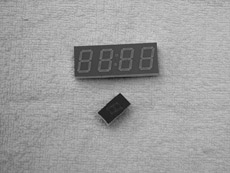

Figure 6.22 shows how the numbers from 0 to 9 are obtained by turning ON different segments of the display.
7-segment displays are available in two different configurations: common cathode and common anode. As shown in Figure 6.23, in common cathode configuration, all the cathodes of all segment LEDs are connected together to the ground. The segments are turned ON by applying a logic 1 to the required segment LED via current limiting resistors. In common cathode configuration the 7-segment LED is connected to the microcontroller in current sourcing mode.
In common anode configuration, the anode terminals of all the LEDs are connected together as shown in Figure 6.24. This common point is then normally connected to the supply voltage. A segment is turned ON by connecting its cathode terminal to logic 0 via a current limiting resistor. In common anode configuration the 7-segment LED is connected to the microcontroller in current sinking mode.

In this project, a Kingbright SA52-11 red common anode 7-segment display is used. This is a 13mm (0.52 inch) display with ten pins that includes a segment LED for the decimal point. Table 6.7 shows the pin configuration of this display.
The circuit diagram of the project is shown in Figure 6.25. A PIC18F452 type microcontroller is used with a 4MHz resonator. Segments a to g of the display are connected to PORTC of the microcontroller through 290-ohm current limiting resistors. Before driving the display, we have to know the relationship between the numbers to be displayed and the corresponding segments to be turned ON, and this is shown in Table 6.8. For example, to display number 3 we have to send the hexadecimal number 0×4F to PORTC, which turns ON segments a,b,c,d, and g. Similarly, to display number 9 we have to send the hexadecimal number 0×6F to PORTC which turns ON segments a,b,c,d,f, and g.
Table 6.8. Displayed number and data sent to PORTC
Number | x g f e d c b a | PORTC Data |
|---|---|---|
0 | 0 0 1 1 1 1 1 1 | 0×3F |
1 | 0 0 0 0 0 1 1 0 | 0×06 |
2 | 0 1 0 1 1 0 1 1 | 0×5B |
3 | 0 1 0 0 1 1 1 1 | 0×4F |
4 | 0 1 1 0 0 1 1 0 | 0×66 |
5 | 0 1 1 0 1 1 0 1 | 0×6D |
6 | 0 1 1 1 1 1 0 1 | 0×7D |
7 | 0 0 0 0 0 1 1 1 | 0×07 |
8 | 0 1 1 1 1 1 1 1 | 0×7F |
9 | 0 1 1 0 1 1 1 1 | 0×6F |
x is not used, taken as 0. | ||
The operation of the project is shown in Figure 6.26 with a PDL. At the beginning of the program an array called SEGMENT is declared and filled with the relationships between the numbers 0 and 9 and the data to be sent to PORTC. The PORTC pins are then configured as outputs, and a variable is initialized to 0. The program then enters an endless loop where the variable is incremented between 0 and 9 and the corresponding bit pattern to turn ON the appropriate segments is sent to PORTC continuously with a one-second delay between outputs.
The program is called SEVEN1.C and the listing is given in Figure 6.27. At the beginning of the program character variables Pattern and Cnt are declared, and Cnt is cleared to 0. Then Table 6.8 is implemented using array SEGMENT. After configuring the PORTC pins as outputs, the program enters an endless loop using a for statement. Inside the loop the bit pattern corresponding to the contents of Cnt is found and stored in variable Pattern. Because we are using a common anode display, a segment is turned ON when it is at logic 0 and thus the bit pattern is inverted before it is sent to PORTC. The value of Cnt is then incremented between 0 and 9, after which the program waits for a second before repeating the above sequence.
Table 6.27. Program listing
/******************************************************* 7-SEGMENT DISPLAY =================In this project a common anode 7-segment LED display is connected to PORTCof a PIC18F452 microcontroller and the microcontroller is operated from a 4MHzresonator. The program displays numbers 0 to 9 on the display with a one seconddelay between each output.Author: Dogan IbrahimDate: July 2007File: SEVEN1.C********************************************************/void main(){ unsigned char Pattern, Cnt = 0; unsigned char SEGMENT[] = {0x3F,0x06,0x5B,0x4F,0x66,0x6D, 0x7D,0x07,0x7F,0x6F}; TRISC = 0; // PORTC are outputs for(;;) // Endless loop { Pattern = SEGMENT[Cnt]; // Number to send to PORTC Pattern = ~Pattern; // Invert bit pattern PORTC = Pattern; // Send to PORTC Cnt++; if(Cnt == 10) Cnt = 0; // Cnt is between 0 and 9 Delay_ms(1000); // 1 second delay }} |
Note that the program can be made more readable if we create a function to display the required number and then call this function from the main program. Figure 6.28 shows the modified program (called SEVEN2.C). A function called Display is created with an argument called no. The function gets the bit pattern from local array SEGMENT indexed by no, inverts it, and then returns the resulting bit pattern to the calling program.
Table 6.28. Modified program listing
/************************************************************** 7-SEGMENT DISPLAY ==================In this project a common anode 7-segment LED display is connected toPORTC of a PIC18F452 microcontroller and the microcontroller isoperated from a 4MHz resonator. The program displays numbers 0 to 9 onthe display with a one second delay between each output.In this version of the program a function called “Display” is used to display thenumber.Author: Dogan IbrahimDate: July 2007File: SEVEN2.C**************************************************************///// This function displays a number on the 7-segment LED.// The number is passed in the argument list of the function.//unsigned char Display(unsigned char no){ unsigned char Pattern; unsigned char SEGMENT[] = {0x3F,0x06,0x5B,0x4F,0x66,0x6D, 0x7D,0x07,0x7F,0x6F}; Pattern = SEGMENT[no]; Pattern = ~ Pattern; // Pattern to return return (Pattern);}//// Start of MAIN Program//void main(){ unsigned char Cnt = 0; TRISC = 0; // PORTC are outputs for(;;) // Endless loop { PORTC = Display(Cnt); // Send to PORTC Cnt++; if(Cnt == 10) Cnt = 0; // Cnt is between 0 and 9 Delay_ms(1000); // 1 second delay }} |
This project is similar to Project 6.5, but here multiplexed two digits are used instead of just one digit and a fixed number. In this project the number 25 is displayed. In multiplexed LED applications (see Figure 6.29) the LED segments of all the digits are tied together and the common pins of each digit are turned ON separately by the microcontroller. When each digit is displayed only for several milliseconds, the eye cannot tell that the digits are not ON all the time. This way we can multiplex any number of 7-segment displays together. For example, to display the number 53, we have to send 5 to the first digit and enable its common pin. After a few milliseconds, number 3 is sent to the second digit and the common point of the second digit is enabled. When this process is repeated continuously, it appears to the user that both displays are ON continuously.
Some manufacturers provide multiplexed multidigit displays, such as 2-, 4-, or 8-digit multiplexed displays, in single packages. The display used in this project is the DC56-11EWA, which is a red 0.56-inch common-cathode two-digit display having 18 pins and the pin configuration as shown in Table 6.9. This display can be controlled from the microcontroller as follows:
Send the segment bit pattern for digit 1 to segments a to g
Enable digit 1
Wait for a few milliseconds
Disable digit 1
Send the segment bit pattern for digit 2 to segments a to g
Enable digit 2
Wait for a few milliseconds
Disable digit 2
Repeat these steps continuously
The segment configuration of the DC56-11EWA display is shown in Figure 6.30. In a multiplexed display application the segment pins of corresponding segments are connected together. For example, pins 11 and 16 are connected as the common a segment, pins 15 and 10 are connected as the common b segment, and so on.
The block diagram of this project is shown in Figure 6.31. The circuit diagram is given in Figure 6.32. The segments of the display are connected to PORTC of a PIC18F452-type microcontroller, operated with a 4MHz resonator. Current limiting resistors are used on each segment of the display. Each digit is enabled using a BC108-type transistor switch connected to port pins RB0 and RB1 of the microcontroller. A segment is turned on when a logic 1 is applied to the base of the corresponding segment transistor.


At the beginning of the program PORTB and PORTC pins are configured as outputs. The program then enters an endless loop where first of all the Most Significant Digit (MSD) of the number is calculated, function Display is called to find the bit pattern and then sent to the display, and digit 1 is enabled. Then, after a small delay, digit 1 is disabled, the Least Significant Digit (LSD) of the number is calculated, function Display is called to find the bit pattern and then sent to the display, and digit 2 is enabled. Then again after a small delay, digit 2 is disabled, and this process repeats indefinitely. Figure 6.33 shows the PDL of the project.
Table 6.33. PDL of the project
START Create SEGMENT table Configure PORTB as outputs Configure PORTC as outputs Initialize CNT to 25 DO FOREVER Find MSD digit Get bit pattern from SEGMENT Enable digit 1 Wait for a while Disable digit 1 Find LSD digit Get bit pattern from SEGMENT Enable digit 2 Wait for a while Disable digit 2 ENDDOEND |
The program is named SEVEN3.C, and the listing is shown in Figure 6.34. DIGIT1 and DIGIT2 are defined as equal to bit 0 and bit 1 of PORTB respectively. The value to be displayed (the number 25) is stored in variable Cnt. An endless loop is formed using a for statement. Inside the loop, the MSD of the number is calculated by dividing the number by 10. Function Display is then called to find the bit pattern to send to PORTC. Then digit 1 is enabled by setting DIGIT1 = 1 and the program waits for 10ms. After this, digit 1 is disabled and the LSD of the number is calculated using the mod operator (“%”) and sent to PORTC. At the same time, digit 2 is enabled by setting DIGIT2 = 1 and the program waits for 10ms. After this time digit 2 is disabled, and the program repeats forever.
Table 6.34. Program listing
/************************************************************** Dual 7-SEGMENT DISPLAY ======================In this project two common cathode 7-segment LED displays are connected toPORTC of a PIC18F452 microcontroller and the microcontroller is operatedfrom a 4MHz resonator. Digit 1 (left digit) enable pin is connected to port pinRB0 and digit 2 (right digit) enable pin is connected to port pin RB1 of themicrocontroller. The program displays number 25 on the displays.Author: Dogan IbrahimDate: July 2007File: SEVEN3.C**************************************************************/#define DIGIT1 PORTB.F0#define DIGIT2 PORTB.F1//// This function finds the bit pattern to be sent to the port to display a number// on the 7-segment LED. The number is passed in the argument list of the function.//unsigned char Display(unsigned char no){ unsigned char Pattern; unsigned char SEGMENT[] = {0x3F,0x06,0x5B,0x4F,0x66,0x6D, 0x7D,0x07,0x7F,0x6F}; Pattern = SEGMENT[no]; // Pattern to return return (Pattern);}//// Start of MAIN Program//void main(){ unsigned char Msd, Lsd, Cnt = 25; TRISC = 0; // PORTC are outputs TRISB = 0; // RB0, RB1 are outputs DIGIT1 = 0; // Disable digit 1 DIGIT2 = 0; // Disable digit 2 for(;;) // Endless loop { |
This project is similar to Project 6 but here the microcontroller’s timer interrupt is used to refresh the displays. In Project 6 the microcontroller was busy updating the displays every 10ms and could not perform any other tasks. For example, the program given in Project 6 cannot be used to make a counter with a one-second delay between counts, as the displays cannot be updated while the program waits for one second.
In this project a counter is designed to count from 0 to 99, and the display is refreshed every 5ms inside the timer interrupt service routine. The main program can then perform other tasks, in this example incrementing the count and waiting for one second between counts.
In this project Timer 0 is operated in 8-bit mode. The time for an interrupt is given by:
Time = (4 × clock period) × Prescaler × (256 − TMR0L) |
where Prescaler is the selected prescaler value, and TMR0L is the value loaded into timer register TMR0L to generate timer interrupts every Time period.
In our application the clock frequency is 4MHz, that is, clock period = 0.25μs, and Time = 5ms. Selecting a prescaler value of 32, the number to be loaded into TMR0L can be calculated as follows:
or
Thus, TMR0L should be loaded with 100. The value to be loaded into TMR0 control register T0CON can then be found as:

Thus, T0CON register should be loaded with hexadecimal 0×C4. The next register to be configured is the interrupt control register INTCON, where we will disable priority based interrupts and enable the global interrupts and TMR0 interrupts:

Taking the don’t-care entries (X) as 0, the hexadecimal value to be loaded into register INTCON is 0×A0.
When an interrupt occurs, the program automatically jumps to the interrupt service routine. Inside this routine we have to reload register TMR0L, reenable the TMR0 interrupts, and clear the TMR0 interrupt flag bit. Setting INTCON register to 0×20 reenables the TMR0 interrupts and at the same time clears the TMR0 interrupt flag.
The operations to be performed can thus be summarized as follows:
In the main program:
Load TMR0L with 100
Set T0CON to 0×C4
Set INTCON to 0×A0
Increment the counter with 1-second delays
In the interrupt service routine:
Re-load TMR0L to 100
Refresh displays
Set INTCON to 0×20 (reenable TMR0 interrupts and clear timer interrupt flag)
The circuit diagram of this project is same as in Figure 6.32 where a dual 7-segment display is connected to PORTB and PORTC of a PIC18F452 microcontroller.
The PDL of the project is shown in Figure 6.35. The program is in two sections: the main program and the interrupt service routine. Inside the main program, TMR0 is configured to generate interrupts every 5ms and the counter is incremented with a one-second delay. Inside the interrupt service routine, the timer interrupt is reenabled and the display digits are refreshed alternately every 5ms.
Table 6.35. PDL of the project
MAIN PROGRAM: START Configure PORTB as outputs Configure PORTC as outputs Clear variable Cnt to 0 Configure TMR0 to generate interrupts every 5ms DO FOREVER Increment Cnt between 0 and 99 Delay 1 second ENDO ENDINTERRUPT SERVICE ROUTINE: START Re-configure TMR0 IF Digit 1 updated THEN Update digit 2 ELSE Update digit 1 END END |
The program is called SEVEN4.C, and the program listing is given in Figure 6.36. At the beginning of the main program PORTB and PORTC are configured as outputs. Then register T0CON is loaded with 0×C4 to enable the TMR0 and set the prescaler to 32. TMR0L register is loaded with 100 so that an interrupt is generated after 5ms. The program then enters an endless loop where the value of Cnt is incremented every second.
Table 6.36. Program of the project
/*********************************************************** Dual 7-SEGMENT DISPLAY COUNTER ==============================In this project two common cathode 7-segment LED displays are connected toPORTC of a PIC18F452 microcontroller and the microcontroller is operatedfrom a 4MHz resonator. Digit 1 (left digit) enable pin is connected to port pin RB0and digit 2 (right digit) enable pin is connected to port pin RB1 of the microcontroller.The program counts up from 0 to 99 with one second delay between each count.The display is updated in a timer interrupt service routine atevery 5ms.Author: Dogan IbrahimDate: July 2007File: SEVEN4.C************************************************************/#define DIGIT1 PORTB.F0#define DIGIT2 PORTB.F1unsigned char Cnt = 0;unsigned char Flag = 0;//// This function finds the bit pattern to be sent to the port to display a number// on the 7-segment LED. The number is passed in the argument list of the function.//unsigned char Display(unsigned char no){ unsigned char Pattern; unsigned char SEGMENT[] = {0x3F,0x06,0x5B,0x4F,0x66,0x6D, 0x7D,0x07,0x7F,0x6F}; Pattern = SEGMENT[no]; // Pattern to return return (Pattern);}//// TMR0 timer interrupt service routine. The program jumps to the ISR at// every 5ms.//void interrupt (){ unsigned char Msd, Lsd; TMR0L = 100; // Re-load TMR0 INTCON = 0x20; // Set T0IE and clear T0IF Flag = ~ Flag; // Toggle Flag if(Flag == 0) // Do digit 1 { |
Inside the interrupt service routine, register TMR0L is reloaded, TMR0 interrupts are reenabled, and the timer interrupt flag is cleared so that further timer interrupts can be generated. The display digits are then updated alternately. A variable called Flag is used to determine which digit to update. Function Display is called, as in Project 6, to find the bit pattern to be sent to PORTC.
In Figure 6.36 the display counts as 00 01...09 10 11...99 00 01... (i.e., the first digit is shown as 0 for numbers less than 10). The program could be modified so the first digit is blanked if the number to be displayed is less than 10. The modified program (called SEVEN5.C) is shown in Figure 6.37. Here, the first digit (MSD) is not enabled if the number to be displayed is 0.
Table 6.37. Modified program
/****************************************** Dual 7-SEGMENT DISPLAY COUNTER ==============================In this project two common cathode 7-segment LED displays areconnected to PORTC of a PIC18F452 microcontroller and themicrocontroller is operated from a 4MHz resonator. Digit 1 (leftdigit) enable pin is connected to port pin RB0 and digit 2(right digit) enable pin is connected to port pin RB1 of themicrocontroller. The program counts up from 0 to 99 with onesecond delay between each count.The display is updated in a timer interrupt service routine atevery 5ms.In this version of the program the first digit is blanked if thenumber is 0.Author: Dogan IbrahimDate: July 2007File: SEVEN5.C*****************************************/#define DIGIT1 PORTB.F0#define DIGIT2 PORTB.F1unsigned char Cnt = 0;unsigned char Flag = 0;//// This function finds the bit pattern to be sent to the port to display a number// on the 7-segment LED. The number is passed in the argument list of the function.//unsigned char Display(unsigned char no){ unsigned char Pattern; unsigned char SEGMENT[] = {0x3F,0x06,0x5B,0x4F,0x66,0x6D, 0x7D,0x07,0x7F,0x6F}; Pattern = SEGMENT[no]; // Pattern to return return (Pattern);}//// TMR0 timer interrupt service routine. The program jumps to the// ISR at every 5ms.//void interrupt (){ unsigned char Msd, Lsd; |
In this project a voltmeter with LCD display is designed. The voltmeter can be used to measure voltages 0–5V. The voltage to be measured is applied to one of the analog inputs of a PIC18F452-type microcontroller. The microcontroller reads the analog voltage, converts it into digital, and then displays it on an LCD.
In microcontroller systems the output of a measured variable is usually displayed using LEDs, 7-segment displays, or LCD displays. LCDs make it possible to display alphanumeric or graphical data. Some LCDs have forty or more character lengths with the capability to display several lines. Other LCD displays can be used to display graphics images. Some modules offer color displays, while others incorporate backlighting so they can be viewed in dimly lit conditions.
There are basically two types of LCDs as far as the interface technique is concerned: parallel and serial. Parallel LCDs (e.g., Hitachi HD44780) are connected to a microcontroller by more than one data line and the data is transferred in parallel form. Both four and eight data lines are commonly used. A four-wire connection saves I/O pins but is slower since the data is transferred in two stages. Serial LCDs are connected to the microcontroller by only one data line, and data is usually sent to the LCD using the standard RS-232 asynchronous data communication protocol. Serial LCDs are much easier to use, but they cost more than the parallel ones.
The programming of a parallel LCD is a complex task and requires a good understanding of the internal operation of the LCD controllers, including the timing diagrams. Fortunately, the mikroC language provides special library commands for displaying data on alphanumeric as well as graphic LCDs. All the user has to do is connect the LCD to the microcontroller, define the LCD connection in the software, and then send special commands to display data on the LCD.
The HD44780 is one of the most popular alphanumeric LCD modules and is used both in industry and by hobbyists. This module is monochrome and comes in different sizes.
Modules with 8, 16, 20, 24, 32, and 40 columns are available. Depending on the model chosen, the number of rows may be 1, 2, or 4. The display provides a 14-pin (or 16-pin) connector to a microcontroller. Table 6.10 gives the pin configuration and pin functions of a 14-pin LCD module. The following is a summary of the pin functions:
VSS is the 0V supply or ground. The VDD pin should be connected to the positive supply. Although the manufacturers specify a 5V DC supply, the modules will usually work with as low as 3V or as high as 6V.
Pin 3, named VEE, is the contrast control pin. This pin is used to adjust the contrast of the display and should be connected to a variable voltage supply. A potentiometer is normally connected between the power supply lines with its wiper arm connected to this pin so that the contrast can be adjusted.
Pin 4 is the register select (RS), and when this pin is LOW, data transferred to the display is treated as commands. When RS is HIGH, character data can be transferred to and from the module.
Pin 5 is the read/write (R/W) line. This pin is pulled LOW in order to write commands or character data to the LCD module. When this pin is HIGH, character data or status information can be read from the module.
Pin 6 is the enable (E) pin, which is used to initiate the transfer of commands or data between the module and the microcontroller. When writing to the display, data is transferred only on the HIGH-to-LOW transition of this line. When reading from the display, data becomes available after the LOW-to-HIGH transition of the enable pin, and this data remains valid as long as the enable pin is at logic HIGH.
Pins 7 to 14 are the eight data bus lines (D0 to D7). Data can be transferred between the microcontroller and the LCD module using either a single 8-bit byte or as two 4-bit nibbles. In the latter case, only the upper four data lines (D4 to D7) are used. The 4-bit mode means that four fewer I/O lines are used to communicate with the LCD. In this book we are using only an alphanumeric-based LCD and only the 4-bit interface.
The mikroC compiler assumes by default that the LCD is connected to the microcontroller as follows:
LCD             Microcontroller port

D7              Bit 7 of the port
D6              Bit 6 of the port
D5              Bit 5 of the port
D4              Bit 4 of the port
E               Bit 3 of the port
RS              Bit 2 of the port
where port is the port name specified using the Lcd_Init statement.
For example, we can use the statement Lcd_Init(&PORTB) if the LCD is connected to PORTB with the default connection.
It is also possible to connect the LCD differently, using the command Lcd_Config to define the connection.
Figure 6.38 shows the block diagram of the project. The microcontroller reads the analog voltage, converts it to digital, formats it, and then displays it on the LCD.
The circuit diagram of the project is shown in Figure 6.39. The voltage to be measured (between 0 and 5V) is applied to port AN0 where this port is configured as an analog input in software. The LCD is connected to PORTC of the microcontroller as in the default four-wire connection. A potentiometer is used to adjust the contrast of the LCD display.
The PDL of the project is shown in Figure 6.40. At the beginning of the program PORTC is configured as output and PORTA is configured as input. Then the LCD and the A/D converter are configured. The program then enters an endless loop where analog input voltage is converted to digital and displayed on the LCD. The process is repeated every second.
The program is called SEVEN6.C, and the program listing is given in Figure 6.41. At the beginning of the program PORTC is defined as output and PORTA as input. Then the LCD is configured and the text “VOLTMETER” is displayed on the LCD for two seconds. The A/D is then configured by setting register ADCON1 to 0 × 80 so the A/D result is right-justified, Vref voltage is set to VDD (+5V), and all PORTA pins are configured as analog inputs.
Table 6.41. Program listing
/******************************************************* VOLTMETER WITH LCD DISPLAY ============================In this project an LCD is connected to PORTC. Also, input port AN0 is used asanalog input. Voltage to be measured is applied to AN0. The microcontrollerreads the analog voltage, converts into digital, and then displays on the LCD.Analog input range is 0 to 5V. A PIC18F452 type microcontroller is used in thisproject, operated with a 4MHz resonator.Analog data is read using the Adc_Read built-in function. This function uses theinternal RC clock for A/D timing.The LCD is connected to the microcontroller as follows:Microcontroller LCD RC7 D7 RC6 D6 RC5 D5 RC4 D4 RC3 Enable RC2 RSAuthor: Dogan IbrahimDate: July 2007File: SEVEN6.C******************************************************///// Start of MAIN Program. Configure LCD and A/D converter//void main(){ unsigned long Vin, mV; unsigned char op[12]; unsigned char i,j,lcd[5]; TRISC = 0; // PORTC are outputs (LCD) TRISA = 0xFF; // PORTA is input//// Configure LCD// Lcd_Init(&PORTC); // LCD is connected to PORTC Lcd_Cmd(LCD_CLEAR); Lcd_Out(1,1,“VOLTMETER”); Delay_ms(2000);// |
The main program loop starts with a for statement. Inside this loop the LCD is cleared, and analog data is read from channel 0 (pin AN0) using the statement Adc_Read(0). The converted digital data is stored in variable Vin which is declared as an unsigned long. The A/D converter is 10-bits wide and thus there are 1024 steps (0 to 1023) corresponding to the reference voltage of 5000mV. Each step corresponds to 5000mV/1024 = 4.88mV. Inside the loop, variable Vin is converted into millivolts by multiplying by 5000 and dividing into 1024. The division is done by shifting right by 10 digits. At this point variable mV contains the converted data in millivolts.
Function LongToStr is called to convert mV into a string in character array op. LongToStr converts a long variable into a string having a fixed width of eleven characters. If the resulting string is fewer than eleven characters, the left column of the data is filled with space characters.
The leading blanks are then removed and the data is stored in a variable called lcd. Function Lcd_Out is called to display the data on the LCD starting from column 5 of row 1. For example, if the measured voltage is 1267mV, it is displayed on the LCD as:
mV = 1267 |
The voltage displayed in Figure 6.41 is not very accurate, since integer arithmetic has been performed in the calculation and the voltage is calculated by multiplying the A/D output by 5000 and then dividing the result by 1024 using integer division. Although the multiplication is accurate, the accuracy of the measurement is lost when the number is divided by 1024. A more accurate result can be obtained by scaling the number before it is displayed, as follows.
First, multiply the number Vin by a factor to remove the integer division. For example, since 5000/1024 = 4.88, we can multiply Vin by 488. For the display, we can calculate the integer part of the result by dividing the number into 100, and then the fractional part can be calculated as the remainder. The integer part and the fractional part can be displayed with a decimal point in between. This technique has been implemented in program SEVEN7.C as shown in Figure 6.42. In this program variables Vdec and Vfrac store the integer and the fractional parts of the number respectively. The decimal part is then converted into a string using function LongToStr and leading blanks are removed. The parts of the fractional number are called ch1 and ch2. These are converted into characters by adding 48 (i.e., character “0”) and then displayed at the next cursor positions using the LCD command Lcd_Chr_Cp.
Table 6.42. A more accurate program
/******************************************* VOLTMETER WITH LCD DISPLAY ============================In this project an LCD is connected to PORTC. Also, input portAN0 is used as analog input. Voltage to be measured is appliedto AN0. The microcontroller reads the analog voltage, convertsinto digital, and then displays on the LCD.Analog input range is 0 to 5V. A PIC18F452 type microcontrolleris used in this project, operated with a 4MHz resonator.Analog data is read using the Adc_Read built-in function. Thisfunction uses the internal RC clock for A/D timing.The LCD is connected to the microcontroller as follows:Microcontroller LCD RC7 D7 RC6 D6 RC5 D5 RC4 D4 RC3 Enable RC2 RSThis program displays more accurate results than program SEVEN6.C.The voltage is displayed as follows: mV = nnnn.mmAuthor: Dogan IbrahimDate: July 2007File: SEVEN7.C******************************************///// Start of MAIN Program. Configure LCD and A/D converter//void main(){ unsigned long Vin, mV,Vdec,Vfrac; unsigned char op[12]; unsigned char i,j,lcd[5],ch1,ch2; TRISC = 0; // PORTC are outputs (LCD) TRISA = 0xFF; // PORTA is input//// Configure LCD |
We could also calculate and display more accurate results by using floating point arithmetic, but since this uses huge amounts of memory it should be avoided if possible.
Keypads are small keyboards used to enter numeric or alphanumeric data into microcontroller systems. Keypads are available in a variety of sizes and styles, from 2 × 2 to 4 × 4 or even bigger.
This project uses a 4 × 4 keypad (shown in Figure 6.43) and an LCD to design a simple calculator.
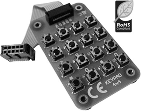
Figure 6.44 shows the structure of the keypad used in this project which consists of sixteen switches formed in a 4 × 4 array and named numerals 0–9, Enter, “+”, “.”, “-”, “*”, and “/”. Rows and columns of the keypad are connected to PORTB of a microcontroller which scans the keypad to detect when a switch is pressed. The operation of the keypad is as follows:
A logic 1 is applied to the first column via RB0.
Port pins RB4 to RB7 are read. If the data is nonzero, a switch is pressed. If RB4 is 1, key 1 is pressed, if RB5 is 1, key 4 is pressed, if RB6 is 1, key 9 is pressed, and so on.
A logic 1 is applied to the second column via RB1.
Again, port pins RB4 to RB7 are read. If the data is nonzero, a switch is pressed. If RB4 is 1, key 2 is pressed, if RB5 is 1, key 6 is pressed, if RB6 is 1, key 0 is pressed, and so on.
This process is repeated for all four columns continuously.
In this project a simple integer calculator is designed. The calculator can add, subtract, multiply, and divide integer numbers and show the result on the LCD. The operation of the calculator is as follows: When power is applied to the system, the LCD displays text “CALCULATOR” for 2 seconds. Then text “No1:” is displayed in the first row of the LCD and the user is expected to type the first number and then press the ENTER key. Then text “No2:” is displayed in the second row of the LCD, where the user enters the second number and presses the ENTER key. After this, the appropriate operation key should be pressed. The result is displayed on the LCD for five seconds and then the LCD is cleared, ready for the next calculation. The example that follows shows how numbers 12 and 20 can be added:
No1: 12 ENTER
No2: 20 ENTER
Op: +
Res = 32
In this project the keyboard is labeled as follows:
1   2   3   4
5   6   7   8
9   0       ENTER
+   −   X   /
One of the keys, between 0 and ENTER, is not used in this project.
The block diagram of the project is shown in Figure 6.45. The circuit diagram is given in Figure 6.46. A PIC18F452 microcontroller with a 4MHz resonator is used in the project. Columns of the keypad are connected to port pins RB0–RB3 and rows are connected to port pins RB4–RB7 via pull-down resistors. The LCD is connected to PORTC in default mode, as in Figure 6.39. An external reset button is also provided to reset the microcontroller should it be necessary.


The project PDL is shown in Figure 6.47. The program consist of two parts: function getkeypad and the main program. Function getkeypad receives a key from the keypad. Inside the main program the two numbers and the required operation are received from the keypad. The microcontroller performs the required operation and displays the result on the LCD.
Table 6.47. Project PDL
Function getkeypad: START IF a key is pressed Get the key code (0 to 15) Return the key code ENDIF ENDMain program: START Configure LCD Wait 2 seconds DO FOREVER Display No1: Read first number Display No2: Read second number Display Op: Read operation Perform operation Display result Wait 5 seconds ENDDO END |
The program listing for the program KEYPAD.C is given in Figure 6.48. Each key is given a numeric value as follows:
0     1     2    3
4     5     6    7
8     9     10   11
12    13    14   15
Table 6.48. Program listing
/******************************************************* CALCULATOR WITH KEYPAD AND LCD ===============================In this project a 4 x 4 keypad is connected to PORTB of a PIC18F452microcontroller. Also an LCD is connected to PORTC. The project is asimple calculator which can perform integer arithmetic.The keys are organized as follows: 0 1 2 3 4 5 6 7 8 9 10 11 12 13 14 15 The keys are labeled as follows: 1 2 3 4 5 6 7 8 9 0 Enter + - * / Author: Dogan IbrahimDate: July 2007File: KEYPAD.C******************************************************/#define MASK 0xF0#define Enter 11#define Plus 12#define Minus 13#define Multiply 14#define Divide 15//// This function gets a key from the keypad//unsigned char getkeypad(){ unsigned char i, Key = 0; PORTB = 0x01; // Start with column 1 while((PORTB & MASK) == 0) // While no key pressed { PORTB = (PORTB << 1); // next column Key++; // column number if(Key == 4) { PORTB = 0x01; // Back to column 1 Key = 0; |
The program consists of a function called getkeypad, which reads the pressed keys, and the main program. Variable MyKey stores the key value (0 to 15) pressed, variables Op1 and Op2 store respectively the first and second numbers entered by the user. All these variables are cleared to zero at the beginning of the program. A while loop is then formed to read the first number and store in variable Op1. This loop exits when the user presses the ENTER key. Similarly, the second number is read from the keyboard in a second while loop. Then the operation to be performed is read and stored in variable MyKey, and a switch statement is used to perform the required operation and store the result in variable Calc. The result is converted into a string array using function LongToStr. The leading blank characters are then removed as in Project 8. The program displays the result on the LCD, waits for five seconds, and then clears the screen and is ready for the next calculation. This process is repeated forever.
Function getkeypad receives a key from the keypad. We start by sending a 1 to column 1, and then we check all the rows. When a key is pressed, a logic 1 is detected in the corresponding row and the program jumps out of the while loop. Then a for loop is used to find the actual key pressed by the user as a number from 0 to 15.
It is important to realize that when a key is pressed or released, we get what is known as contact noise, where the key output pulses up and down momentarily, producing a number of logic 0 and 1 pulses at the output. Switch contact noise is usually removed either in hardware or by programming in a process called contact debouncing. In software the simplest way to remove the contact noise is to wait for about 20ms after a switch key is pressed or switch key is released. In Figure 6.46, contact debouncing is accomplished in function getkeypad.
In the program listing in Figure 6.48, a function called getkeypad has been developed to read a key from the keyboard. The mikroC language has built-in functions called Keypad_Read and Keypad_Released to read a key from a keypad when a key is pressed and when a key is released respectively. Figure 6.49 shows a modified program (KEYPAD2.C) listing using the Keypad_Released function to implement the preceding calculator project. The circuit diagram is the same as in Figure 6.46.
Table 6.49. Modified program listing
/******************************************************* CALCULATOR WITH KEYPAD AND LCD ===============================In this project a 4 x 4 keypad is connected to PORTB of a PIC18F452 microcontroller. Also an LCD is connected to PORTC. The project is a simple calculator which can perform integer arithmetic.The keys are labeled as follows: 1 2 3 4 5 6 7 8 9 0 Enter + - * /In this program mikroC built-in functions are used.Author: Dogan IbrahimDate: July 2007File: KEYPAD2.C******************************************************/#define Enter 12#define Plus 13#define Minus 14#define Multiply 15#define Divide 16//// Start of MAIN program//void main(){ unsigned char MyKey, i,j,lcd[5],op[12]; unsigned long Calc, Op1, Op2; TRISC = 0; // PORTC are outputs (LCD)//// Configure LCD// Lcd_Init(&PORTC); // LCD is connected to PORTC Lcd_Cmd(LCD_CLEAR); Lcd_Out(1,1,“CALCULATOR”); // Display CALCULATOR Delay_ms(2000); Lcd_Cmd(LCD_CLEAR);//// Configure KEYPAD// Keypad_Init(&PORTB); // Keypad on PORTB |
Before using the Keypad_Released function we have to call the Keypad_Init function to tell the microcontroller what the keypad is connected to. Keypad_Released detects when a key is pressed and then released. When released, the function returns a number between 1 and 16 corresponding to the key pressed. The remaining parts of the program are the same as in Figure 6.48.
Serial communication is a simple means of sending data long distances quickly and reliably. The most common serial communication method is based on the RS232 standard, in which standard data is sent over a single line from a transmitting device to a receiving device in bit serial format at a prespecified speed, also known as the baud rate, or the number of bits sent each second. Typical baud rates are 4800, 9600, 19200, 38400, etc.
RS232 serial communication is a form of asynchronous data transmission where data is sent character by character. Each character is preceded with a start bit, seven or eight data bits, an optional parity bit, and one or more stop bits. The most common format is eight data bits, no parity bit, and one stop bit. The least significant data bit is transmitted first, and the most significant bit is transmitted last.
A logic high is defined at −12V, and a logic 0 is at +12V. Figure 6.50 shows how character “A” (ASCII binary pattern 0010 0001) is transmitted over a serial line. The line is normally idle at −12V. The start bit is first sent by the line going from high to low. Then eight data bits are sent, starting from the least significant bit. Finally, the stop bit is sent by raising the line from low to high.

In a serial connection, a minimum of three lines is used for communication: transmit (TX), receive (RX), and ground (GND). Serial devices are connected to each other using two types of connectors: 9-way and 25-way. Table 6.11 shows the TX, RX, and GND pins of each type of connectors. The connectors used in RS232 serial communication are shown in Figure 6.51.
As just described, RS232 voltage levels are at ±12V. However, microcontroller input-output ports operate at 0 to +5V voltage levels, so the voltage levels must be translated before a microcontroller can be connected to a RS232 compatible device. Thus the output signal from the microcontroller has to be converted to ±12V, and the input from an RS232 device must be converted into 0 to +5V before it can be connected to a microcontroller. This voltage translation is normally done with special RS232 voltage converter chips. One such popular chip is the MAX232, a dual converter chip having the pin configuration shown in Figure 6.52. The device requires four external 1mF capacitors for its operation.
In the PIC18 series of microcontrollers, serial communication can be handled either in hardware or in software. The hardware option is easy. PIC18 microcontrollers have built-in USART (universal synchronous asynchronous receiver transmitter) circuits providing special input-output pins for serial communication. For serial communication all the data transmission is handled by the USART, but the USART has to be configured before receiving and transmitting data. With the software option, all the serial bit timing is handled in software, and any input-output pin can be programmed and used for serial communication.
In this project a PC is connected to the microcontroller using an RS232 cable. The project operates as a simple integer calculator where data is sent to the microcontroller using the PC keyboard and displayed on the PC monitor.
A sample calculation is as follows:
  CALCULATOR PROGRAM

  Enter First Number: 12
  Enter Second Number: 2
  Enter Operation: +
  Result = 14
Figure 6.53 shows the block diagram of the project. The circuit diagram is given in Figure 6.54. This project uses a PIC18F452 microcontroller with a 4MHz resonator, and the built-in USART is used for serial communication. The serial communication lines of the microcontroller (RC6 and RC7) are connected to a MAX232 voltage translator chip and then to the serial input port (COM1) of a PC using a 9-pin connector.
The PDL of the project is shown in Figure 6.55. The project consists of a main program and two functions called Newline and Text_To_User. Function Newline sends a carriage-return and line-feed to the serial port. Function Text_To_User sends a text message to USART. The main program receives two numbers and the operation to be performed from the PC keyboard. The numbers are echoed on the PC monitor. The result of the operation is also displayed on the monitor.
Table 6.55. Project PDL
Function Newline: START Send carriage-return to USART Send line-feed to USART ENDFunction Text_To_Usart START Get text from the argument Send text to USART ENDMain program: START Configure USART to 9600 Baud DO FOREVER Display “CALCULATOR PROGRAM” Display “Enter First Number: ” Read first number Display “Enter Second Number: ” Read second number Display “Operation: ” Read operation Perform operation Display “Result= ” Display the result ENDDO END |
The program listing of the project is shown in Figure 6.56. The program consists of a main program and two functions called Newline and Text_To_Usart. Function Newline sends a carriage return and line feed to the USART to move the cursor to the next line. Function Text_To_Usart sends a text message to the USART.
Table 6.56. Program listing
/************************************************************ CALCULATOR WITH PC INTERFACE ==============================In this project a PC is connected to a PIC18F452 microcontroller. The project is a simple integer calculator. User enters the numbers using the PC keyboard. Results are displayed on the PC monitor.The following operations can be performed: + - * / This program uses the built in USART of the microcontroller. The USART is configured to operate with 9600 Baud rate.The serial TX pin is RC6 and the serial RX pin is RC7.Author: Dogan IbrahimDate: July 2007File: SERIAL1.C***********************************************************/#define Enter 13#define Plus ‘+’#define Minus ‘-’#define Multiply ‘*’#define Divide ‘/’//// This function sends carriage-return and line-feed to USART//void Newline(){ Usart_Write(0x0D); // Send carriage-return Usart_Write(0x0A); // Send line-feed}//// This function sends a text to USART//void Text_To_Usart(unsigned char *m){ unsigned char i; i = 0; while(m[i] != 0) { // Send TEXT to USART Usart_Write(m[i]); i++; |
At the beginning of the program various messages used in the program are defined as msg1 to msg5. The USART is then initialized to 9600 baud using the mikroC library routine Usart_Init. Then the heading “CALCULATOR PROGRAM” is displayed on the PC monitor. The program reads the first number from the keyboard using the library function Usart_Read. Function Usart_Data_Ready checks when a new data byte is ready before reading it. Variable Op1 stores the first number. Similarly, another loop is formed and the second number is read into variable Op2. The program then reads the operation to be performed (+ − * /). The required operation is performed inside a switch statement and the result is stored in variable Calc. The program then converts the result into string format by calling library function LongToStr. Leading blanks are removed from this string, and the final result is stored in character array kbd and sent to the USART to display on the PC keyboard.
The program can be tested using a terminal emulator software such as HyperTerminal, which is distributed free of charge with Windows operating systems. The steps to test the program follow (these steps assume serial port COM2 is used):
Connect the RS232 output from the microcontroller to the serial input port of a PC (e.g., COM2)
Start HyperTerminal terminal emulation software and give a name to the session
Select File -> New connection -> Connect using and select COM2
Select the baud rate as 9600, data bits as 8, no parity bits, and 1 stop bit
Reset the microcontroller
An example output from the HyperTerminal screen is shown in Figure 6.57.

The preceding example made use of the microcontroller’s USART and thus its special serial I/O pins. Serial communication can also be handled entirely in software, without using the USART. In this method, any pin of the microcontroller can be used for serial communication.
The calculator program given in Project 10 can be reprogrammed using the mikroC software serial communications library functions known as the Software Uart Library.
The modified program listing is given in Figure 6.58. The circuit diagram of the project is same as in Figure 6.54 (i.e., RC6 and RC7 are used for serial TX and RX respectively), although any other port pins can also be used. At the beginning of the program the serial I/O port is configured by calling function Soft_Uart_Init. The serial port name, the pins used for TX and RX, the baud rate, and the mode are specified. The mode tells the microcontroller whether or not the data is inverted. Setting mode to 1 inverts the data. When a MAX232 chip is used, the data should be noninverted (i.e., mode = 0).
Table 6.58. Modified program
/************************************************************ CALCULATOR WITH PC INTERFACE ==============================In this project a PC is connected to a PIC18F452 microcontroller. The project is a simple integer calculator. User enters the numbers using the PC keyboard. Results are displayed on the PC monitor.The following operations can be performed: + - * /In this program the serial communication is handled in softwareand the serial port is configured to operate with 9600 Baud rate.Port pins RC6 and RC7 are used for serial TX and RX respectively.Author: Dogan IbrahimDate: July 2007File: SERIAL2.C***********************************************************/#define Enter 13#define Plus ‘+’#define Minus ‘-’#define Multiply ‘*’#define Divide ‘/’//// This function sends carriage-return and line-feed to USART//void Newline(){ Soft_Uart_Write(0x0D); // Send carriage-return Soft_Uart_Write(0x0A); // Send line-feed}//// This function sends a text to serial port//void Text_To_Usart(unsigned char *m){ unsigned char i; i = 0; while(m[i] != 0) { // Send TEXT to serial port Soft_Uart_Write(m[i]); |
Serial data is then output using function Soft_Uart_Write. Serial data is input using function Soft_Uart_Read. As the reading is a nonblocking function, it is necessary to check whether or not a data byte is available before attempting to read. This is done using the error argument of the function. The remaining parts of the program are the same.