
The development of a microcontroller-based system is a complex process. Development tools are hardware and software tools designed to help programmers develop and test systems in a relatively short time. There are many such tools, and a discussion of all of them is beyond the scope of this book. This chapter offers a brief review of the most common tools.
The tools for developing software and hardware for microcontroller-based systems include editors, assemblers, compilers, debuggers, simulators, emulators, and device programmers. A typical development cycle starts with writing the application program using a text editor. The program is then translated into an executable code with the help of an assembler or compiler. If the program has several modules, a linker is used to combine them into a single application. Any syntax errors are detected by the assembler or compiler and must be corrected before the executable code can be generated. Next, a simulator is used to test the application program without the target hardware. Simulators are helpful in checking the correctness of an algorithm or a program with limited or no input-outputs, and most errors can be removed during simulation. Once the program seems to be working and the programmer is happy with it, the executable code is loaded to the target microcontroller chip using a device programmer, and the system logic is tested. Software and hardware tools such as in-circuit debuggers and in-circuit emulators can analyze the program’s operation and display the variables and registers in real time with the help of breakpoints set in the program.
Software development tools are computer programs, usually run on personal computers, that allow the programmer (or system developer) to create, modify, and test applications programs. Some common software development tools are:
Text editors
Assemblers/compilers
Simulators
High-level language simulators
Integrated development environments (IDEs)
A text editor is used to create or edit programs and text files. The Windows operating system comes with a text editor program called Notepad. Using Notepad, we can create a new program file, modify an existing file, or display or print the contents of a file. It is important to realize that programs used for word processing, such as Microsoft Word, cannot be used for this purpose, since they embed word formatting characters such as bold, italic, and underline within the text.
Most assemblers and compilers come with built-in text editors, making it possible to create a program and then assemble or compile it without having to exit from the editor. These editors provide additional features as well, such as automatic keyword highlighting, syntax checking, parenthesis matching, and comment line identification. Different parts of a program can be shown in different colors to make the program more readable (e.g., comments in one color and keywords in another). Such features help to eliminate syntax errors during the programming stage, thus speeding up the development process.
Assemblers generate executable code from assembly language programs, and that generated code can then be loaded into the flash program memory of a PIC18-based microcontroller. Compilers generate executable code from high-level language programs. The compilers used most often for PIC18 microcontrollers are BASIC, C, and PASCAL.
Assembly language is used in applications where processing speed is critical and the microcontroller must respond to external and internal events in the shortest possible time. However, it is difficult to develop complex programs using assembly language, and assembly language programs are not easy to maintain.
High-level languages, on the other hand, are easier to learn, and complex programs can be developed and tested in a much shorter time. High-level programs are also maintained more easily than assembly language programs.
Discussions of programming in this book are limited to the C language. Many different C language compilers are available for developing PIC18 microcontroller-based programs. Some of the popular ones are:
CCS C (http://www.ccsinfo.com)
Hi-Tech C (http://htsoft.com)
C18 C (http://www.microchip.com)
mikroC C (http://www.mikroe.com)
Wiz-C C (http://www.fored.co.uk)
Although most C compilers are essentially the same, each one has its own additions or modifications to the standard language. The C compiler used in this book is mikroC, developed by mikroElektronika.
A simulator is a computer program that runs on a PC without the microcontroller hardware. It simulates the behavior of the target microcontroller by interpreting the user program instructions using the microcontroller instruction set. Simulators can display the contents of registers, memory, and the status of input-output ports as the user program is interpreted. Breakpoints can be set to stop the program and check the contents of various registers at desired locations. In addition, the user program can be executed in a single-step mode, so the memory and registers can be examined as the program executes one instruction at a time as a key is pressed.
Some assembler programs contain built-in simulators. Three popular PIC18 microcontroller assemblers with built-in simulators are:
MPLAB IDE (http://www.microchip.com)
Oshon Software PIC18 simulator (http://www.oshonsoft.com)
Forest Electronics PIC18 assembler (http://www.fored.co.uk)
High-level language simulators, also known as source-level debuggers, are programs that run on a PC and locate errors in high-level programs. The programmer can set breakpoints in high-level statements, execute the program up to a breakpoint, and then view the values of program variables, the contents of registers, and memory locations at that breakpoint.
A source-level debugger can also invoke hardware-based debugging using a hardware debugger device. For example, the user program on the target microcontroller can be stopped and the values of various variables and registers can be examined.
Some high-level language compilers, including the following three, have built-in source-level debuggers:
C18 C
Hi-Tech PIC18 C
mikroC C
Integrated development environments (IDEs) are powerful PC-based programs which include everything to edit, assemble, compile, link, simulate, and source-level debug a program, and then download the generated executable code to the physical microcontroller chip using a programmer device. These programs are in graphical user interface (GUI), where the user can select various options from the program without having to exit it. IDEs can be extremely useful when developing microcontroller-based systems. Most PIC18 high-level language compilers are IDEs, thus enabling the programmer to do most tasks within a single software development tool.
Numerous hardware development tools are available for the PIC18 microcontrollers. Some of these products are manufactured by Microchip Inc., and some by third-party companies. The most ones are:
Development boards are invaluable microcontroller development tools. Simple development boards contain just a microcontroller and the necessary clock circuitry. Some sophisticated development boards contain LEDs, LCD, push buttons, serial ports, USB port, power supply circuit, device programming hardware, and so on.
This section is a survey of various commercially available PIC18 microcontroller development boards and their specifications.
The LAB-XUSB Experimenter board (see Figure 5.1), manufactured by microEngineering Labs Inc., can be used in 40-pin PIC18-based project development. The board is available either assembled or as a bare board.
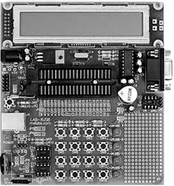
The board contains:
40-pin ZIF socket for PIC microcontroller
5-volt regulator
20MHz oscillator
Reset button
16-switch keypad
Two potentiometers
Four LEDs
2-line by 20-character LCD module
Speaker
RS232 interface
USB connector
Socket for digital-to-analog converter (device not included)
Socket for I2C serial EEPROM (device not included)
Socket for Dallas DS1307 real-time clock (device not included)
Pads for Dallas DS18S20 temperature sensors (device not included)
In-circuit programming connector
Prototyping area for additional circuits
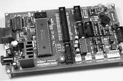
Th PICDEM 2 Plus kit (see Figure 5.2), manufactured by Microchip Inc., can be used in the development of PIC18 microcontroller-based projects.

2 × 16 LCD display
Piezo sounder driven by PWM signal
Active RS 232 port
On-board temperature sensor
Four LEDs
Two push-button switches and master reset
Sample PIC18F4520 and PIC16F877A flash microcontrollers
MPLAB REAL ICE/MPLAB ICD 2 connector
Source code for all programs
Demonstration program displaying a real-time clock and ambient temperature
Generous prototyping area
Works off of a 9V battery or DC power pack
The PICDEM 4 kit (see Figure 5.3), manufactured by Microchip Inc., can be used in the development of PIC18 microcontroller-based projects.

The board contains:
Three different sockets supporting 8-, 14-, and 18-pin DIP devices
On-board +5V regulator for direct input from 9V, 100 mA AC/DC wall adapter
Active RS-232 port
Eight LEDs
2 × 16 LCD display
Three push-button switches and master reset
Generous prototyping area
I/O expander
Supercapacitor circuitry
Area for an LIN transceiver
MPLAB ICD 2 connector
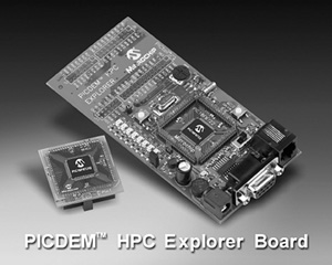
The PICDEM HPC Explorer development board (see Figure 5.4), manufactured by Microchip Inc., can be used in the development of high pin count PIC18-series microcontroller-based projects.
The main features of this board are:
PIC18F8722, 128K flash, 80-pin TQFP microcontroller
Supports PIC18 J-series devices with plug-in modules
10MHz crystal oscillator (to be used with internal PLL to provide 40MHz operation)
Power supply connector and programmable voltage regulator, capable of operation from 2.0 to 5.5V
Potentiometer (connected to 10-bit A/D, analog input channel)
Temperature sensor demo included
RS-232 port (9-pin D-type connector, UART1)
Reset button
32KHz crystal for real-time clock demonstration
The MK-1 Universal PIC development board (see Figure 5.5), manufactured by Baji Labs, can be used for developing PIC microcontroller-based projects with up to 40 pins. The board has a key mechanism which allows any peripheral device to be mapped to any pin of the processor, making the board very flexible. A small breadboard area is also provided, enabling users to design and test their own circuits.

The board has the following features:
On-board selectable 3.3V or 5V
16 × 2 LCD character display (8- or 4-bit mode supported)
4-digit multiplexed 7-segment display
Ten LED bar graph (can be used as individual LEDs)
Eight-position dip switch
Socketed oscillator for easy change of oscillators
Stepper motor driver with integrated driver
I2C real-time clock with crystal and battery backup support
I2C temperature sensor with 0.5 degree C precision
Three potentiometers for direct A/D development
16-button telephone keypad wired as 4 × 4 matrix
RS232 driver with standard DB9 connector
Socketed SPI and I2C EEPROM
RF Xmit and receive sockets
IR Xmit and receive
External drive buzzer
Easy access to pull up resistors
AC adapter included
The SSE452 development board (see Figure 5.6), manufactured by Shuan Shizu Electronic Laboratory, can be used for developing PIC18-based microcontroller projects, especially the PIC18FXX2 series of microcontrollers, and also for programming the microcontrollers.

The main features of this board are:
One PCB suitable for any 28- or 40-pin PIC18 devices
Three external interrupt pins
Two input-capture/output-compare/pulse-width modulation modules (CCP)
Support SPI, I2C functions
10-bit analog-to-digital converter
RS-232 connector
Two debounced push-button switches
An 8-bit DIP-switch for digital input
4 × 4 keypad connector
Rotary encoder with push button
TC77 SPI temperature sensor
EEPROM (24LC04B)
2 × 20 bus expansion port
ICD2 connector
On-board multiple digital signals from 1Hz to 8MHz
Optional devices are 2 × 20 character LCD, 48/28-pin ZIF socket
The SSE8720 development board (see Figure 5.7), manufactured by Shuan Shizu Electronic Laboratory, can be used for the development of PIC18-based microcontroller projects. A large amount of memory and I/O interface is provided, and the board can also be used to program microcontrollers.

The main features of this board are:
20MHz oscillator with socket
One DB9 connector provides EIA232 interface
In-circuit debugger (ICD) connector
Four debounced switches, and one reset switch
4 × 4 keypad connector
One potentiometer for analog-to-digital conversion
Eight red LEDs
8-bit DIP switch for digital inputs
2 × 20 character LCD module
Twenty-four different digital signals, from 1Hz to 16MHz
One I2C EEPROM with socket
SPI-compatible digital temperature sensor
SPI-compatible real-time clock
CCP1 output via an NPN transistor
The SSE8680 development board (see Figure 5.8), manufactured by Shuan Shizu Electronic Laboratory, can be used for developing PIC18-based microcontroller projects. The board supports CAN network, and a large amount of memory and I/O interface is provided. The board can also be used to program microcontrollers.

The main features of this board are:
20MHz oscillator with socket
One DB9 connector provides EIA232 interface
In-circuit debugger (ICD) connector
Four debounced switches, and one reset switch
4 × 4 keypad connector
8 red LEDs
8-bit DIP switch for digital inputs
2 × 20 character LCD module
Twenty-four different digital signals, from 1Hz to 16MHz
On-board 5V regulator
One I2C EPROM with socket
SPI-compatible digital temperature sensor
SPI-compatible real-time clock
CCP1 output via an NPN transistor
Rotary encoder
CAN transceiver
The PIC18F4520 development kit (see Figure 5.9), manufactured by Custom Computer Services Inc., includes a C compiler (PCWH), a prototyping board with PIC18F4520 microcontroller, an in-circuit debugger, and a programmer.
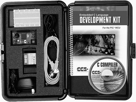
The main features of this development kit are:
PCWH compiler
PIC18F4520 prototyping board
Breadboard area
93LC56 serial EEPROM chip
DS1631 digital thermometer chip
NJU6355 real-time clock IC with attached 32.768KHz crystal
Two-digit 7-segment LED module
In-circuit debugger/programmer
DC adapter and cables
Custom Computer Services manufactures a number of other PIC18 microcontroller-based development kits and prototyping boards, such as development kits for CAN, Ethernet, Internet, USB, and serial buses. More information is available on the company’s web site.
The BIGPIC4 is a sophisticated development kit (Figure 5.10) that supports the latest 80-pin PIC18 microcontrollers. The kit comes already assembled, with a PIC18F8520 microcontroller installed and working at 10MHz. It includes an on-board USB port, an on-board programmer, and an in-circuit debugger. The microcontroller on the board can be replaced easily.
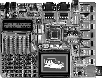
The main features of this development kit are:
Forty-six buttons
Forty-six LEDs
USB connector
External or USB power supply
Two potentiometers
Graphics LCD
2 × 16 text LCD
MMC/SD memory card slot
Two serial RS232 ports
In-circuit debugger
Programmer
PS2 connector
Digital thermometer chip (DS1820)
Analog inputs
Reset button
The BIGPIC4 is used in some of the projects in this book.
The FUTURLEC PIC18F458 training board is a very powerful development kit (see Figure 5.11) based on the PIC18F458 microcontroller and developed by Futurlec (www.futurlec.com). The kit comes already assembled and tested. One of its biggest advantages is its low cost, at under $45.
PIC18F458 microcontroller with 10MHz crystal
RS232 communication
Test LED
Optional real-time clock chip with battery backup
LCD connection
Optional RS485/RS422 with optional chip
CAN and SPI controller
I2C expansion
In-circuit programming
Reset button
Speaker
Relay socket
All port pins are available at connectors
After the program is written and translated into executable code, the resulting HEX file is loaded to the target microcontroller’s program memory with the help of a device programmer. The type of device programmer depends on the type of microcontroller to be programmed. For example, some device programmers can only program PIC16 series, some can program both PIC16 and PIC18 series, while some are designed to program other microcontroller models (e.g., the Intel 8051 series).
Some microcontroller development kits include on-board device programmers, so the microcontroller chip does not need to be removed and inserted into a separate programming device. This section describes some of the popular device programmers used to program PIC18 series of microcontrollers.
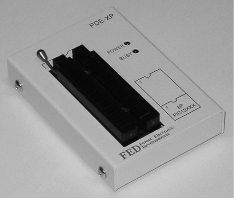
The USB programmer, manufactured by Forest Electronics (see Figure 5.12), can be used to program most PIC microcontrollers with up to 40 pins, including the PIC18 series. The device is connected to the USB port of a PC and takes its power from this port.
The Mach X programmer (Figure 5.13), manufactured by Custom Computer Services Inc., can program microcontrollers of the PIC12, PIC14, PIC16, and PIC18 series ranging from 8 to 40 pins. It can also read the program inside a microcontroller and then generate a HEX file. In-circuit debugging is also supported by this programmer.

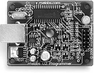
The Melabs U2 device programmer (see Figure 5.14), manufactured by microEngineering Labs Inc., can be used to program most PIC microcontroller chips having from 8 to 40 pins. The device is USB-based and receives its power from the USB port of a PC.
The EasyProg PIC is a low-cost programmer (Figure 5.15) used with microcontrollers of the PIC16 and PIC18 series having up to 40 pins. It connects to a PC via a 9-pin serial cable.

The PIC Prog Plus is another low-cost programmer (Figure 5.16) that can be used to program most PIC microcontrollers. The device is powered from an external 12V DC supply.

An in-circuit debugger is hardware connected between a PC and the target microcontroller test system used to debug real-time applications quickly and easily. With in-circuit debugging, a monitor program runs in the PIC microcontroller in the test circuit. The programmer can set breakpoints on the PIC, run code, single-step the program, and examine variables and registers on the real device and, if required, change their values. An in-circuit debugger uses some memory and I/O pins of the target PIC microcontroller during debugging operations. Some in-circuit debuggers only debug assembly language programs. Other, more powerful debuggers can debug high-level language programs.
This section discusses some of the popular in-circuit debuggers used in PIC18 microcontroller-based system applications.
The ICD2, a low-cost in-circuit debugger (see Figure 5.17) manufactured by Microchip Inc., can debug most PIC microcontroller-based systems. With the ICD2, programs are downloaded to the target microcontroller chip and executed in real time. This debugger supports both assembly language and C language programs.

The ICD2 connects to a PC through either a serial RS232 or a USB interface. The device acts like an intelligent interface between the PC and the test system, allowing the programmer to set breakpoints, look into the test system, view registers and variables at breakpoints, and single-step through the user program. It can also be used to program the target PIC microcontroller.
The ICD-U40 is an in-circuit debugger (see Figure 5.18) manufactured by Custom Computer Services Inc. to debug programs developed with their CCS C compiler. The device operates with a 40MHz clock frequency, is connected to a PC via the USB interface, and is powered from the USB port. The company also manufactures a serial-port version of this debugger called ICD-S40, which is powered from the target test system.

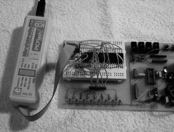
The PICFlash 2 in-circuit debugger (see Figure 5.19) is manufactured by mikroElektronika and can be used to debug programs developed in mikroBasic, mikroC, or mikroPascal languages. The device is connected to a PC through its USB interface. Power is drawn from the USB port so the debugger requires no external power supply. The PICFlash 2 is included in the BIGPIC4 development kit. Details on the use of this in-circuit debugger are discussed later in this chapter.

The in-circuit emulator (ICE) is one of the oldest and the most powerful devices for debugging a microcontroller system. It is also the only tool that substitutes its own internal processor for the one in the target system. Like all in-circuit debuggers, the emulator’s primary function is target access—the ability to examine and change the contents of registers, memory, and I/O. Since the emulator replaces the CPU, it does not require a working CPU in the target system. This makes the in-circuit emulator by far the best tool for troubleshooting new or defective systems.
In general, each microcontroller family has its own set of in-circuit emulators. For example, an in-circuit emulator designed for the PIC16 microcontrollers cannot be used for PIC18 microcontrollers. Moreover, the cost of in-circuit emulators is usually quite high. To keep costs down, emulator manufacturers provide a base board which can be used with most microcontrollers in a given family, for example, with all PIC microcontrollers, and also make available probe cards for individual microcontrollers. To emulate a new microcontroller in the same family, then, only the specific probe card has to be purchased.
Several models of in-circuit emulators are available on the market. The following four are some of the more popular ones.
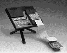
The MPLAB ICE 4000 in-circuit emulator (Figure 5.20), manufactured by Microchip Inc., can be used to emulate microcontrollers in the PIC18 series. It consists of an emulator pod connected with a flex cable to device adapters for the specific microcontroller. The pod is connected to the PC via its parallel port or USB port. Users can insert an unlimited number of breakpoints in order to examine register values.
The RICE3000 is a powerful in-circuit emulator (Figure 5.21), manufactured by Smart Communications Ltd, for the PIC16 and PIC18 series of microcontrollers.

The device consists of a base unit with different probe cards for the various members of the PIC microcontroller family. It provides full-speed real-time emulation up to 40MHz, supports observation of floating point variables and complex variables such as arrays and structures, and provides source level and symbolic debugging in both assembly and high-level languages.
The ICEPIC 3 is a modular in-circuit emulator (see Figure 5.22), manufactured by RF Solutions, for the PIC12/16 and PIC18 series of microcontrollers. It connects to the PC via its USB port and consists of a mother board with additional daughter boards for each microcontroller type. The daughter boards are connected to the target system with device adapters. A trace board can be added to capture and analyze execution addresses, opcodes, and external memory read/writes.

The PICE-MC, a highly sophisticated emulator (see Figure 5.23) manufactured by Phyton Inc., supports most PIC microcontrollers and consists of a main board, pod, and adapters. The main board contains the emulator logic, memory, and an interface to the PC. The pod contains a slave processor that emulates the target microcontroller. The adapters are the mechanical parts that physically connect to the microcontroller sockets of the target system. The PICE-MC provides source-level debugging of programs written in both assembly and high-level languages. A large memory is provided to capture target system data. The user can set up a large number of breakpoints and can access the program and data memories to display or change their contents.

Building an electronic circuit requires connecting the components as shown in the relevant circuit diagram, usually by soldering the components together on a strip board or a printed circuit board (PCB). This approach is appropriate for circuits that have been tested and are functioning as desired, and also when the circuit is being made permanent. However, making a PCB design for just a few applications—for instance, while still developing the circuit—is not economical.
Instead, while the circuit is still under development, the components are usually assembled on a solderless breadboard. A typical breadboard (see Figure 5.24) consists of rows and columns of holes spaced so that integrated circuits and other components can be fitted inside them. The holes have spring actions so the component leads are held tightly in place. There are various types and sizes of breadboards, suitable for circuits of different complexities. Breadboards can also be stacked together to make larger boards for very complex circuits. Figure 5.25 shows the internal connection layout of the breadboard in Figure 5.24.

The top and bottom halves of the breadboard are entirely separate. Columns 1 to 20 in rows A to F are connected to each other on a column basis. Rows G to L in columns 1 to 20 are likewise connected to each other on a column basis. Integrated circuits are placed such that the legs on one side are on the top half of the breadboard, and the legs on the other side are on the bottom half. The two columns on the far left of the board are usually reserved for the power and ground connections. Connections between components are usually made with stranded (or solid) wires plugged into the holes to be connected.
Figure 5.26 shows a breadboard holding two integrated circuits and a number of resistors and capacitors.

The nice thing about breadboard design is that the circuit can be modified easily and quickly, and ideas can be tested without having to solder the components. Once a circuit has been tested and is working satisfactorily, the components are easily removed and the breadboard can be used for other projects.
In this book we are using the mikroC compiler developed by mikroElektronika. Before using this compiler, we need to know how the mikroC integrated development environment (IDE) is organized and how to write, compile, and simulate a program in the mikroC language. In this section we will look at the operation of the mikroC IDE in detail.
A free 2K program size limited version of the mikroC IDE, available on the mikroElektronika web site (www.mikroe.com), is adequate for most small or mediumsized applications. Alternatively, you can purchase a license and turn the limited version into a fully working, unlimited IDE to use for projects of any size and complexity.
After installing the mikroC IDE, a new icon should appear by default on your desktop. Double-click this icon to start the IDE.
After the mikroC icon is double-clicked to start the IDE, the screen shown in Figure 5.27 is displayed by default.

The screen is divided into four areas: the top-left section, the bottom-left section, the middle section, and the bottom section.
The top left, the Code Explorer section, displays every declared item in the source code. In the example in Figure 5.28, main is listed under Functions and variables Sum and i are listed under main.

There are two additional tabs in the Code Explorer. As shown in Figure 5.29, the QHelp tab lists all the available built-in functions and library functions for a quick reference.

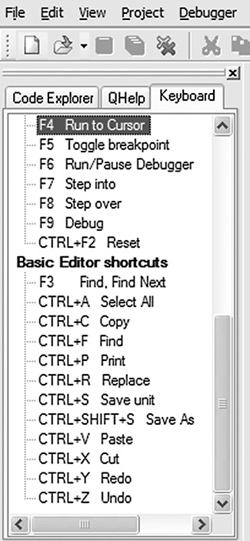
The Keyboard tab lists all the available keyboard shortcuts in mikroC IDE (see Figure 5.30).
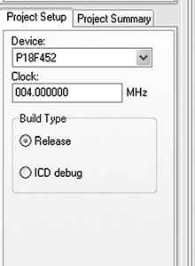
In the bottom-left section, called Project Setup (see Figure 5.31), the microcontroller device type, clock rate, and build type are specified. The build type can be either Release, which is the normal compiler operating mode, or ICD debug, if the program is to be debugged using the in-circuit debugger.
The Project Setup section has a tab called Project Summary which lists all the types of files used in the project, as shown in Figure 5.32.

The middle section is the Code Editor, an advanced text editor. Programs are written in this section of the screen. The Code Editor supports:
Code Assistant
Parameter Assistant
Code Template
Auto Correct
Bookmarks
The Code Assistant is useful when writing a program. Type the first few letters of an identifier and then press the CTRL+SPACE keys to list all valid identifiers beginning with those letters. In Figure 5.33, for example, to locate identifier strlen, the letters str are typed and CTRL+SPACE is pressed. strlen can be selected from the displayed list of matching valid words by using keyboard arrows and pressing ENTER.

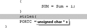
The Parameter Assistant is invoked when a parenthesis is opened after a function or a procedure name. The expected parameters are listed in a small window just above the parenthesis. In Figure 5.34, function strlen has been entered, and unsigned char *s appears in a small window when a parenthesis is opened.
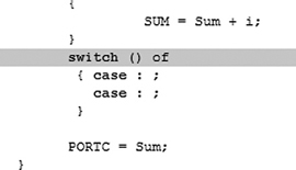
Code Template is used to generate code in the program. For example, as shown in Figure 5.35, typing switch and pressing CTRL+J automatically generates code for the switch statement. We can add our own templates by selecting Tools -> Options -> Auto Complete. Some of the available templates are array, switch, for, and if.
Auto Correct corrects typing mistakes automatically. A new list of recognized words can be added by selecting Tools -> Options -> Auto Correct Tab.
Bookmarks make the navigation easier in large code. We can set bookmarks by entering CTRL+SHIFT+number, and can then jump to the bookmark by pressing CTRL+number, where number is the bookmark number.
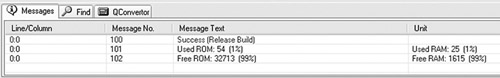
The bottom section of the screen, also called the Message Window, consists of three tabs: Messages, Find, and QConverter. Compilation errors and warnings are reported under the Messages tab. Double-clicking on a message line highlights the line where the error occurred. A HEX file can be generated only if the source file contains no errors. Figure 5.36 shows the results of a successful compilation listed in the Message Window. The QConverter tab can be used to convert decimal numbers into binary or hexadecimal, and vice versa.
mikroC files are organized into projects, and all files for a single project are stored in the same folder. By default, a project file has the extension “.ppc”. A project file contains the project name, the target microcontroller device, device configuration flags, the device clock, and list of source files with their paths. C source files have the extension “.c”.
The following example illustrates step-by-step how to create and compile a program source file.
Write a C program to calculate the sum of the integer numbers 1 to 10 and then send the result to PORTC of a PIC18F452-type microcontroller. Assume that eight LEDs are connected to the microcontroller’s PORTC via current limiting resistors. Draw the circuit diagram and show the steps involved in creating and compiling the program.
Figure 5.37 shows the circuit diagram of the project. The LEDs are connected to PORTC using 390 ohm current limiting resistors. The microcontroller is operated from a 4MHz resonator.
The program is created and compiled as follows:
Double-click the mikroC icon to start the IDE.
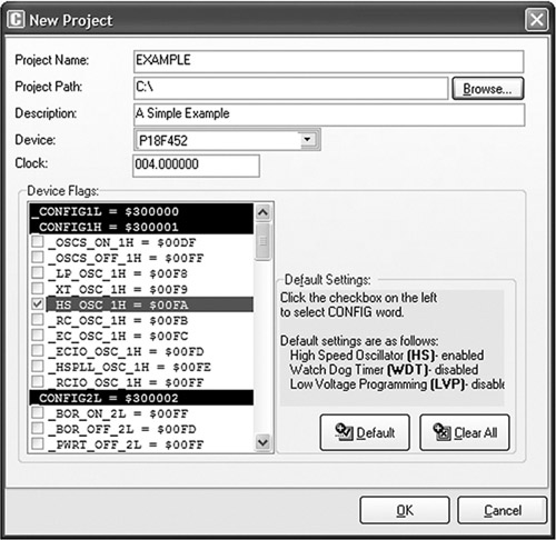
Create a new project called EXAMPLE. Click Project -> New Project and fill in the form, as shown in Figure 5.38, by selecting the device type, the clock, and the configuration fuse.
Enter the following program into the Code Editor section of the IDE:
/********************************************************************** EXAMPLE PROGRAM 8 LEDs are connected to a PIC18F452 type microcontroller. This program calculates the sum of integer numbers from 1 to 10 And then displays the sum on PORTC of the microcontroller. Author: Dogan Ibrahim File: EXAMPLE.C**********************************************************************/
void main()
{

     unsigned int Sum,i;
     TRISC = 0;

     Sum = 0;
     for(i=1; i<= 10; i++)
     {
              Sum = Sum + i;
     }

     PORTC = Sum;
}
Save the program with the name EXAMPLE by clicking File -> Save As. The program will be saved with the name EXAMPLE.C.
Compile the project by pressing CTRL+F9 or by clicking the Build Project button (see Figure 5.39).
If the compilation is successful, a Success message will appear in the Message Window as shown in Figure 5.36. Any program errors will appear in the Message Window and should be corrected before the project proceeds further.

The compiler generates a number of output files, which can be selected by clicking Tools -> Options -> Output. The various output files include:
.ASM file. This is the assembly file of the program. Figure 5.40 shows the EXAMPLE. ASM file.
Table 5.40. EXAMPLE.ASM
; ASM code generated by mikroVirtualMachine for PIC - V. 6.2.1.0 ; Date/Time: 07/07/2007 16:46:12 ; Info: http://www.mikroelektronika.co.yu ; ADDRESS OPCODE ASM ; ---------------------------------------------- $0000 $EF04 F000 GOTO _main $0008 $ _main: ;EXAMPLE.c,14 :: void main() ;EXAMPLE.c,18 :: TRISC = 0; $0008 $6A94 CLRF TRISC, 0 ;EXAMPLES.c,20 :: Sum = 0; $000A $6A15 CLRF main_Sum_L0, 0 $000C $6A16 CLRF main_Sum_L0+1, 0 ;EXAMPLE.c,21 :: for(i=1; i<= 10; i++) $000E $0E01 MOVLW 1 $0010 $6E17 MOVWF main_i_L0, 0 $0012 $0E00 MOVLW 0 $0014 $6E18 MOVWF main_i_L0+1, 0 $0016 $ L_main_0: $0016 $0E00 MOVLW 0 $0018 $6E00 MOVWF STACK_0, 0 $001A $5018 MOVF main_i_L0+1, 0, 0 $001C $5C00 SUBWF STACK_0, 0, 0 $001E $E102 BNZ L_main_3 $0020 $5017 MOVF main_i_L0, 0, 0 $0022 $080A SUBLW 10 $0024 $ L_main_3: $0024 $E307 BNC L_main_1 ;EXAMPLE.c,23 :: SUM = Sum + i; $0026 $5017 MOVF main_i_L0, 0, 0 $0028 $2615 ADDWF main_Sum_L0, 1, 0 $002A $5018 MOVF main_i_L0+1, 0, 0 $002C $2216 ADDWFC main_Sum_L0+1, 1, 0 ;EXAMPLE.c,24 :: } $002E $ L_main_2: ;EXAMPLE.c,21 :: for(i=1; i<= 10; i++) $002E $4A17 INFSNZ main_i_L0, 1, 0 $0030 $2A18 INCF main_i_L0+1, 1, 0 ;EXAMPLE.c,24 :: } $0032 $D7F1 BRA L_main_0 $0034 $ L_main_1: ;EXAMPLE.c,26 :: PORTC = Sum; $0034 $C015 FF82 MOVFF main_Sum_L0, PORTC ;EXAMPLE.c,27 :: } $0038 $D7FF BRA $ |
.LST file. This is the listing file of the program. Figure 5.41 shows the EXAMPLE.LST file.
Table 5.41. EXAMPLE.LST
; ASM code generated by mikroVirtualMachine for PIC - V. 6.2.1.0 ; Date/Time: 07/07/2007 17:07:12 ; Info: http://www.mikroelektronika.co.yu ; ADDRESS OPCODE ASM ; ---------------------------------------------- $0000 $EF04 F000 GOTO _main $0008 $ _main: ;EXAMPLE.c,14 :: void main() ;EXAMPLE.c,18 :: TRISC = 0; $0008 $6A94 CLRF TRISC, 0 ;EXAMPLE.c,20 :: Sum = 0; $000A $6A15 CLRF main_Sum_L0, 0 $000C $6A16 CLRF main_Sum_L0+1, 0 ;EXAMPLE.c,21 :: for(i=1; i<= 10; i++) $000E $0E01 MOVLW 1 $0010 $6E17 MOVWF main_i_L0, 0 $0012 $0E00 MOVLW 0 $0014 $6E18 MOVWF main_i_L0+1, 0 $0016 $ L_main_0: $0016 $0E00 MOVLW 0 $0018 $6E00 MOVWF STACK_0, 0 $001A $5018 MOVF main_i_L0+1, 0, 0 $001C $5C00 SUBWF STACK_0, 0, 0 $001E $E102 BNZ L_main_3 $0020 $5017 MOVF main_i_L0, 0, 0 $0022 $080A SUBLW 10 $0024 $ L_main_3: $0024 $E307 BNC L_main_1 ;EXAMPLE.c,23 :: SUM = Sum + i; $0026 $5017 MOVF main_i_L0, 0, 0 $0028 $2615 ADDWF main_Sum_L0, 1, 0 $002A $5018 MOVF main_i_L0+1, 0, 0 $002C $2216 ADDWFC main_Sum_L0+1, 1, 0 ;EXAMPLE.c,24 :: } $002E $ L_main_2: ;EXAMPLE.c,21 :: for(i=1; i<= 10; i++) $002E $4A17 INFSNZ main_i_L0, 1, 0 $0030 $2A18 INCF main_i_L0+1, 1, 0 ;EXAMPLE.c,24 :: } $0032 $D7F1 BRA L_main_0 $0034 $ L_main_1: ;EXAMPLE.c,26 :: PORTC = Sum; $0034 $C015 FF82 MOVFF main_Sum_L0, PORTC ;EXAMPLE.c,27 :: } $0038 $D7FF BRA $ //** Procedures locations ** //ADDRESS PROCEDURE //---------------------------------------------- $0008 main //** Labels locations ** //ADDRESS LABEL //---------------------------------------------- $0008 _main: $0016 L_main_0: $0024 L_main_3: $002E L_main_2: $0034 L_main_1: //** Variables locations ** //ADDRESS VARIABLE //---------------------------------------------- $0000 STACK_0 $0001 STACK_1 $0002 STACK_2 $0003 STACK_3 $0004 STACK_4 $0005 STACK_5 $0006 STACK_6 $0007 STACK_7 $0008 STACK_8 $0009 STACK_9 $000A STACK_10 $000B STACK_11 $000C STACK_12 $000D STACK_13 $000E STACK_14 $000F STACK_15 $0010 STACK_16 $0011 STACK_17 $0012 STACK_18 $0013 STACK_19 $0014 STACK_20 $0015 main_Sum_L0 $0017 main_i_L0 $0F82 PORTC $0F94 TRISC $0FD8 STATUS $0FD9 FSR2L $0FDA FSR2H $0FDB PLUSW2 $0FDC PREINC2 $0FDD POSTDEC2 $0FDE POSTINC2 $0FDF INDF2 $0FE0 BSR $0FE1 FSR1L $0FE2 FSR1H $0FE3 PLUSW1 $0FE4 PREINC1 $0FE5 POSTDEC1 $0FE6 POSTINC1 $0FE7 INDF1 $0FE8 WREG $0FE9 FSR0L $0FEA FSR0H $0FEB PLUSW0 $0FEC PREINC0 $0FED POSTDEC0 $0FEE POSTINC0 $0FEF INDF0 $0FF3 PRODL $0FF4 PRODH $0FF5 TABLAT $0FF6 TBLPTRL $0FF7 TBLPTRH $0FF8 TBLPTRU $0FF9 PCL $0FFA PCLATH $0FFB PCLATU $0FFD TOSL $0FFE TOSH $0FFF TOSU |
.HEX file. This is the most important output file as it is the one sent to the programming device to program the microcontroller. Figure 5.42 shows the EXAMPLE.HEX file.
The program developed in Section 5.3.2 is simulated following the steps given here, using the simulator in software (release mode). That is, no hardware is used in this simulation.
Describe the steps for simulating the program developed in Example 5.1. Display the values of various variables and PORTC during the simulation while single-stepping the program. What is the final value displayed on PORTC?
The steps are as follows:
Start the mikroC IDE, making sure the program developed in Example 5.1 is displayed in the Code Editor window.
From the drop-down menu select Debugger -> Select Debugger -> Software PIC Simulator, as shown in Figure 5.43.
From the drop-down menu select Run -> Start Debugger. The debugger form shown in Figure 5.44 will appear.
Select the variables we want to see during the simulation. Assuming we want to display the values of variables Sum, i, and PORTC:
Click on Select from variable list and then find and click on the variable name Sum
Click Add to add this variable to the Watch list
Repeat these steps for variable i and PORTC
The debugger window should now look like Figure 5.45.
We can now single-step the program and see the variables changing.
Press the F8 key on the keyboard. You should see a blue line to move down. This shows the line where the program is currently executing. Keep pressing F8 until you are inside the loop and you will see that variables Sum and i have become 1, as shown in Figure 5.46. Recently changed items appear in red. Double-clicking an item in the Watch window opens the Edit Value window, where you can change the value of a variable or register, or display the value in other bases such as decimal, hexadecimal, binary, or as a floating point or character.
Keep pressing F8 until the program comes out of the for loop and executes the line that sends data to PORTC. A this point, as shown in Figure 5.47, i = 11 and Sum = 55.
Press F8 again to send the value of variable Sum to PORTC. As shown in Figure 5.48, in this case PORTC will have the decimal value 55, which is the sum of numbers from 1 to 10.
This is the end of the simulation. Select from drop-down menu Run -> Stop Debugger.


In the above simulation example, we single-stepped through the program to the end and then we could see the final value of PORTC. The next example shows how to set breakpoints in the program and then execute up to a breakpoint.
Describe the steps involved in simulating the program developed in Example 5.1. Set a breakpoint at the end of the program and run the debugger up to this breakpoint. Display the values of various variables and PORTC at this point. What is the final value displayed on PORTC?
The steps are as follows:
Start the mikroC IDE, making sure the program developed in Example 5.1 is displayed in the Code Editor window.
From the drop-down menu select Debugger -> Select Debugger -> Software PIC Simulator.
From the drop-down menu select Run -> Start Debugger.
Select variables Sum, i, and PORTC from the Watch window as described in Example 5.2.
To set a breakpoint at the end of the program, click the mouse at the last closing bracket of the program, which is at line 27, and press F5. As shown in Figure 5.49, you should see a red line at the breakpoint and a little marker in the left column of the Code Editor window.
Now, start the debugger, and press F6 key to run the program. The program will stop at the breakpoint, displaying variables as shown in Figure 5.48.
This is the end of the simulation. Select from drop-down menu Run -> Stop Debugger.

To clear a breakpoint, move the cursor over the line where the breakpoint is and then press F5. To clear all breakpoints in a program, press the SHIFT+CTRL+F5 keys. To display the breakpoints in a program, press the SHIFT+F4 keys.
The following are some other useful debugger commands:
Step Into [F7]. Executes the current instruction and then halts. If the instruction is a call to a routine, the program enters the routine and halts at the first instruction.
Step Over [F8]. Executes the current instruction and then halts. If the instruction is a call to a routine, it skips it and halts at the first instruction following the call.
Step Out [CTRL+F8]. Executes the current instruction and then halts. If the instruction is within a routine, it executes the instruction and halts at the first instruction following the call.
Run to Cursor [F4]. Executes all instructions between the current instruction and the cursor position.
Jump to Interrupt [F2]. Jumps to the interrupt service routine address (address 0x08 for PIC18 microcontrollers) and executes the procedure located at that address.
This section discusses how to use the mikroICD in-circuit debugger (also called the PICFlash 2 programmer) to debug the program developed in Example 5.1. First of all, we have to build the hardware and then connect the in-circuit debugger device. In this example, the hardware is built on a breadboard, and a PICFlash 2 mikroICD in-circuit debugger is used to debug the system. Note that pins RB6 and RB7 are used by the mikroICD and are not available for I/O while mikroICD is active.
The project’s circuit diagram is shown in Figure 5.50. The mikroICD in-circuit debugger is connected to the development circuit using the following pins of the microcontroller:
MCLR
RB6
RB7
+5V
GND

The mikroICD has two modes of operation. In inactive mode all lines from the microcontroller used by the debugger device are connected to the development system. In active mode the MCLR, RB6, and RB7 pins are disconnected from the development system and used to program the microcontroller. After the programming, these lines are restored.
The mikroICD debugger device has a 10-way IDC connector and can be connected to the target system with a 10-way IDC header. Once the development is finished and the mikroICD debugger is removed, opposite pairs of the IDC header can be connected with jumpers. Figure 5.51 shows the system built on a breadboard.
After building the hardware we are ready to program the microcontroller and test the system’s operation with the in-circuit debugger. The steps are as follows:
Start the mikroC IDE, making sure the program developed in Example 5.1 is displayed in the Code Editor window.
Click the Edit Project button (Figure 5.52) and set DEBUG_ON as shown in Figure 5.53.
Select ICD Debug in the Project Setup window as shown in Figure 5.54.
Click the Build Project icon to compile the program with the debugger. After a successful compilation you should see the message Success (ICD Build) in the Message Window.
Make sure the mikroICD debugger device is connected as in Figure 5.50, and select Tools -> PicFlash Programmer from the drop-down menu to program the microcontroller.
From the drop-down menu select Debugger -> Select Debugger -> mikroICD Debugger as shown in Figure 5.55.
From the drop-down menu select Run -> Start Debugger. The debugger form will pop up and select variables Sum, i, and PORTC as described in Example 5.2.
Single-step through the program by pressing the F8 key. You should see the values of variables changing. At the end of the program, decimal value 55 will be sent to PORTC, and LEDs 0,1,2,4, and 5 should be turned ON, as shown in Figure 5.56, corresponding to this number.
Stop the debugger.
In routines that contain delays, the Step Into [F7] and Step Over [F8] commands can take a long time. Run to Cursor [F4] and breakpoints should be used instead.


It is easy to develop microcontroller-based applications with the help of a development board. This section explains how to use the development board BIGPIC4, described earlier in this chapter. The program written in Example 5.1 is compiled and then loaded to the microcontroller using the on-board mikroICD in-circuit emulator. Then the program runs and displays the sum of the numbers 1 to 10 on the LEDs connected to PORTC.
However, before using the development board we need to know how the BIGPIC4 is organized and how to use the various devices on the board.
Figure 5.57 shows the BIGPIC4 development board with the functions of various devices identified with arrows. The board can be powered either from an external power supply (8- to 16-C AC/DC) or from the USB port of a computer, using a jumper. In this application, the board is powered from a USB port.

A 2-row by 16-column LCD can be connected in the board’s upper left corner. The contrast of the LCD can be adjusted with a small potentiometer.
The forty-six LEDs on the board can be connected to the output ports of the microcontroller, selected by switch S2. Figure 5.58 shows how to select the LEDs, using PORTC as an example. 1K resistors are used in series with the LEDs to limit the current. For example, to connect eight LEDs to PORTC we have to set the switch arm marked PORTC of switch S2 to the ON position.

The forty-six push-button switches on the board can be used to program digital inputs to the microcontroller. There is also a push-button switch that acts as the RESET. Jumper J12 determines whether a button press will bring logical 0 or logical 1 to the microcontroller. When the button is not pressed, the pin state is determined by jumper J5.
At the bottom central position, a 128 × 64 pixel graphics LCD can be connected to the board. The contrast of the LCD can be adjusted by a small potentiometer.
The MMC/SD card slot at the bottom right-hand corner of the board supports cards up to 2GB storage capacity.
The RESET button is located just above the MMC/SD card slot.
Above the RESET button are two potentiometers for analog-to-digital converter applications.
All of the microcontroller port pins are available at the connectors situated along the right-hand side of the board. In the top middle portion of the board are two RS232 ports and a connection to a PC keyboard.
The board supports both 64-pin and 80-pin microcontrollers. The board comes with a PIC18F8520 microcontroller connected to the board, operating with a 10MHz crystal.
Further details about the operation of the board can be found in the BIGPIC4 user’s manual.
The steps in developing an application using the BIGPIC4 board are as follows:
Double-click the mikroC icon to start the IDE.
Create a new project called EXAMPLE2 (see Figure 5.59) and select the microcontroller type as PIC18F8520, the clock as 10MHz, and device flags as:
_OSC_HS_1H
_WDT_OFF_2H
_LVP_OFF_4L
_DEBUG_ON_4L
Enter the following program into the Code Editor section of the IDE:
/****************************************************************** EXAMPLE PROGRAM This program uses the PICBIG4 Development Board. 8 LEDs are connected To PORTC of the microcontroller which is a PIC18F8520 operating at 10MHz. This program calculates the sum of integer numbers from 1 to 10 And then displays the sum on PORTC of the microcontroller.
Author: Dogan IbrahimFile: EXAMPLE2.C****************************************************************/
 void main()
 {

      unsigned int Sum,i;
      TRISC = 0;

      Sum = 0;
      for(i=1; i<= 10; i++)
      {
               Sum = Sum + i;
      }

      PORTC = Sum;
}
Save the program with the name EXAMPLE2 by clicking File -> Save As.
Tick option ICD Debug in the Project Setup window. Compile the project by pressing CTRL+F9 or by clicking the Build Project button.
Connect the BIGPIC4 development board to the USB port on the computer. Configure the development board by routing eight LEDs to PORTC: Set the arm marked PORTC on switch S2 to the ON position.
Select Tools -> PicFlash Programmer from the drop-down menu to program the microcontroller.
Select Debugger -> Select Debugger -> mikroICD Debugger.
Start the debugger by clicking Run -> Start Debugger and select variables Sum, i, and PORTC from the Watch window.
Single-step through the program until the end by repeatedly pressing F8. At the end of the program, the PORTC LEDs will turn ON to display decimal 55 (i.e., LEDs 0,1,2,4, and 5 will turn ON).
Stop the debugger.

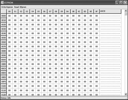
The mikroICD EEPROM window is invoked from the mikroC IDE drop-down menu when the mikroICD debug mode is selected and started, and it displays contents of the PIC internal EEPROM memory. To view the memory, click View -> Debug Windows -> View EEPROM. Figure 5.60 shows an example EEPROM window display.
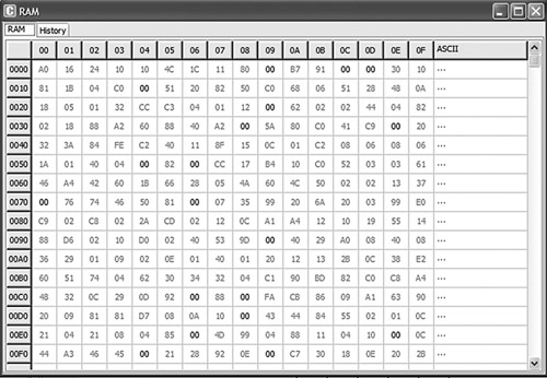
The mikroICD RAM window is invoked from the mikroC IDE drop-down menu when the mikroICD debug mode is selected and started, and it displays contents of the PIC internal RAM memory. To view the memory, click View -> Debug Windows -> View RAM. Figure 5.61 shows an example RAM window display.
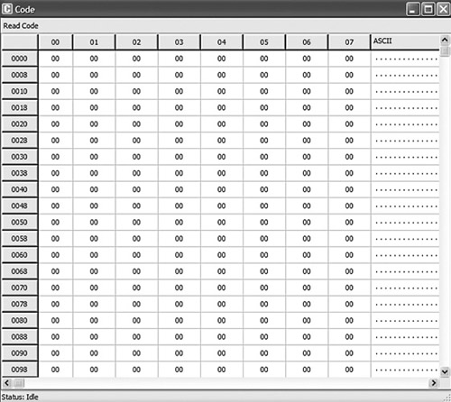
The mikroICD Code window is invoked from the mikroC IDE drop-down menu when the mikroICD debug mode is selected and started, and it displays the contents of the PIC internal code memory. To view the memory, click View -> Debug Windows -> View Code. Figure 5.62 shows an example Code window display.
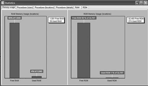
The Statistics window is invoked from the mikroC IDE drop-down menu and it displays various statistical data about our program. To view the statistics window, click View -> View Statistics. Figure 5.63 shows an example Statistics window, which consists of several tabs. The Memory Usage tab displays the amount of RAM (data memory) and ROM (code memory) used. The Procedures tabs display information about the size and locations of the procedures. The RAM and ROM tabs display memory usage in detail.
This chapter has described the PIC microcontroller software development tools (such as text editors, assemblers, compilers, and simulators) and hardware development tools (including development boards and kits, programming devices, in-circuit debuggers, and in-circuit emulators). The mikroC compiler was used in the examples and projects. The steps in developing and testing a mikroC-based C program were presented both with and without a hardware in-circuit debugger, followed by an example of how to use the BIGPIC4 development board, with the on-board in-circuit debugger enabled.